JP5259259B2 - Ultrasonic Doppler diagnostic device - Google Patents
Ultrasonic Doppler diagnostic device Download PDFInfo
- Publication number
- JP5259259B2 JP5259259B2 JP2008146189A JP2008146189A JP5259259B2 JP 5259259 B2 JP5259259 B2 JP 5259259B2 JP 2008146189 A JP2008146189 A JP 2008146189A JP 2008146189 A JP2008146189 A JP 2008146189A JP 5259259 B2 JP5259259 B2 JP 5259259B2
- Authority
- JP
- Japan
- Prior art keywords
- signal
- doppler
- boundary
- spectrum
- doppler spectrum
- Prior art date
- Legal status (The legal status is an assumption and is not a legal conclusion. Google has not performed a legal analysis and makes no representation as to the accuracy of the status listed.)
- Expired - Fee Related
Links
Images


Landscapes
- Ultra Sonic Daignosis Equipment (AREA)
Description
本発明は、超音波のドプラ効果を利用して、血液等の体内の運動体の運動状態を診断する超音波ドプラ診断装置に関する。 The present invention relates to an ultrasonic Doppler diagnostic apparatus for diagnosing the movement state of a moving body such as blood using the Doppler effect of ultrasonic waves.
超音波検査においては、ドプラモードを使用して生体内の運動機能の診断を行なう場合がある。ドプラモードとは、生体内の血流情報をリアルタイムでディスプレイに表示できるようにしたもので、ディスプレイ上に表示されるドプラ信号波形は、時間(横軸)の経過に伴う血流速度(縦軸)とその信号の強度(パワー)の変化(ディスプレイ上では輝度変化で表示される)を示すものである。 In the ultrasonic examination, the Doppler mode may be used to diagnose the motor function in the living body. In Doppler mode, blood flow information in the living body can be displayed on the display in real time. The Doppler signal waveform displayed on the display is the blood flow velocity (vertical axis) along with the passage of time (horizontal axis). ) And a change in the intensity (power) of the signal (displayed as a luminance change on the display).
ここで、検出されるドプラ信号の速度(周波数)がパルス繰り返し周波数(PRF:pulse repetition frequency)で表される一定値(±1/2PRF)を超える場合には、表示されるドプラ波形が折り返すことがある。折り返しのあるドプラ波形を折り返しのないドプラ波形に変換するには、流速レンジやベースライン位置を操作者がマニュアル操作にて適切に調整・設定しなければいけないため、操作に時間がかかり操作者の大きな負担になると共に、診断の作業性が悪かった。 Here, when the speed (frequency) of the detected Doppler signal exceeds a certain value (± 1/2 PRF) represented by a pulse repetition frequency (PRF), the displayed Doppler waveform is folded. There is. To convert a folded Doppler waveform to an unfolded Doppler waveform, the operator must adjust and set the flow velocity range and baseline position appropriately by manual operation. It was a big burden and the workability of the diagnosis was bad.
そこで、操作者の負担を軽減し、診断の作業性を向上させる目的で、検出可能周波数範囲(ナイキスト周波数)に対する信号存在領域を検出することで、自動的に適切な流速レンジ値及び適切なベースライン位置を求め、次に自動的に適切な流速レンジ値及び適切なベースライン位置を設定することが可能な超音波ドプラ診断装置が開発されている(例えば、特許文献1参照。)。
しかしながら、特許文献1の技術に、サンプリング周波数を遮蔽周波数(PRF)の2倍の2×PRFに設定する等のオーバーサンプリング(oversampling)技術を適用することによってドプラ信号を折り返し表示させないようにすると、特許文献1では流速レンジやベースライン位置の自動調整機能が適切に動作せず、適切なドプラ波形表示できない場合がある。
However, if an oversampling technique such as setting the sampling frequency to 2 × PRF that is twice the shielding frequency (PRF) is applied to the technique of
本発明は、このような事情を考慮してなされたもので、操作者とって常に適切なドプラ信号の波形を提示することができる超音波ドプラ診断装置を提供することを目的とする。 The present invention has been made in view of such circumstances, and an object of the present invention is to provide an ultrasonic Doppler diagnostic apparatus that can always present an appropriate waveform of a Doppler signal for an operator.
本発明に係る超音波ドプラ診断装置は、上述した課題を解決するために、被検体内の運動体を含む診断部位との間で超音波を送受信する送受信手段と、前記送受信手段によって得られる受信信号を帯域制限フィルタの遮蔽周波数の2倍以上の周波数でサンプリングして前記運動体に起因するドプラ信号を抽出する抽出手段と、前記抽出手段によって抽出されるドプラ信号を基にドプラ偏移周波数を分析してドプラスペクトラムを生成する手段と、前記ドプラスペクトラムの正の最大を含む第1ドプラスペクトラムを生成し、前記第1ドプラスペクトラムを基に、信号存在領域と信号非存在領域との第1境界を検出し、前記ドプラスペクトラムの負の最大を含む第2ドプラスペクトラムを生成し、前記第2ドプラスペクトラムを基に、信号存在領域と信号非存在領域との第2境界を検出する検出手段と、前記第1境界と前記第2境界との差を基に、前記ドプラスペクトラムの表示体系を調整する調整手段と、前記調整後のドプラスペクトラムをディスプレイ上に表示させる手段と、を有する。 In order to solve the above-described problem, an ultrasonic Doppler diagnostic apparatus according to the present invention transmits / receives ultrasonic waves to / from a diagnostic part including a moving body in a subject, and reception obtained by the transmission / reception means. An extraction means for sampling a signal at a frequency twice or more the shielding frequency of the band limiting filter to extract a Doppler signal caused by the moving body, and a Doppler shift frequency based on the Doppler signal extracted by the extraction means means for generating a Doppler spectrum analyzes, to generate a first de plug spectrum containing positive maximum of the Doppler spectrum, based on the first de Pula spectrum, first the signal existence region and the signal absence region detecting a first boundary to generate a second de plug spectrum containing negative maximum of the Doppler spectrum, based on the second de plug spectrum signal present A detecting means that detect a second boundary between the band and the signal absent region, based on a difference between the second boundary between the first boundary, and adjusting means for adjusting a display system of the Doppler spectrum, the And a means for displaying the adjusted Doppler spectrum on the display.
本発明に係る超音波ドプラ診断装置によると、操作者とって常に適切なドプラ信号の波形を提示することができる。 According to the ultrasonic Doppler diagnostic apparatus according to the present invention, it is possible for an operator to always present an appropriate Doppler signal waveform.
本発明に係る超音波ドプラ診断装置の実施形態について、添付図面を参照して説明する。 An embodiment of an ultrasonic Doppler diagnostic device according to the present invention will be described with reference to the accompanying drawings.
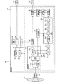
図1は、本実施形態の超音波ドプラ診断装置(超音波診断装置)の構成を示す概略図である。 FIG. 1 is a schematic diagram illustrating a configuration of an ultrasonic Doppler diagnostic apparatus (ultrasonic diagnostic apparatus) according to the present embodiment.
図1は、第1実施形態の超音波ドプラ診断装置10を示す。その超音波ドプラ診断装置10は、大きくは、超音波プローブ11、装置本体12、ディスプレイ13及び操作パネル14によって構成される。
FIG. 1 shows an ultrasonic Doppler
超音波プローブ11は、装置本体12からの駆動パルスを基に患者P内に超音波信号を送波すると共に、エコー信号を受信して電気信号に変換する圧電振動子群を有する。なお、超音波プローブ11としては、例えば、機械式三次元プローブ及び2Dプローブ(マトリクスアレイプローブ)等が挙げられる。
The ultrasonic probe 11 has a piezoelectric vibrator group that transmits an ultrasonic signal into the patient P based on a drive pulse from the
装置本体12は、送受信部21、Bモード画像生成回路(検波回路)22、画像メモリ23、ミキサ24、ローパスフィルタ(LPF)25、90度移相器26、サンプリングパルス発生回路27、ドプラスペクトラム演算部28、第1境界検出回路29、第2境界検出回路30、ドプラスペクトラム調整回路31、表示画像生成回路32、CPU(central processing unit)33、内部記憶装置34、IF(inter face)35及び外部記憶装置36を備える。なお、図示しないが、ミキサ24、LPF25及びドプラスペクトラム演算部28は、それぞれ2チャンネルである。また、本実施形態では、第1境界検出回路29、第2境界検出回路30及びドプラスペクトラム調整回路31は集積回路として構成されるものとして説明するが、それらの全部又は一部はソフトウェア的にモジュール化されたソフトウェアプログラムの実行によって機能されるものであってもよい。
The apparatus
送受信部21は、基準信号発生回路21a、遅延回路(ディレイライン)21b、パルサ回路21c、アンプ21d及び加算回路21eを備える。基準信号発生回路21aは、基準クロックを発生する。遅延回路(後述する受信時の遅延も兼用)21bは、基準信号発生回路21aによって発生される基準クロックを受けて遅延駆動信号を生成する。パルサ回路21cは、遅延回路21bによって生成される遅延駆動信号を受けて超音波プローブ11の圧電振動子群を振動させる。なお、このような送受信部21の送信系は、CPU33の指示に従って、送信周波数、送信駆動電圧(音圧)、送信パルスレート、スキャン領域及びフラッシュ回数等を瞬時に変更可能な機能を有している。特に音圧の変更については、瞬間にその値を切り替え可能なリニアアンプ型の発信部又は複数の電源部を電気的に切り替える機構によって実現される。
The transmission /
送受信部21のアンプ21dは、超音波プローブ11を介して取り込まれたエコー信号をチャンネル毎に増幅する。遅延回路21bは、アンプ21dの出力信号に対して受信指向性を決定するのに必要な遅延時間を与えて、出力信号を遅延させる。加算回路21eは、遅延回路21bの出力信号に対して加算処理を行なう。加算回路21eによる加算により、エコー信号の受信指向性に応じた方向からの反射成分が強調され、受信指向性と送信指向性とにより超音波送受信の総合的なビームが形成される。
The
Bモード画像生成回路22は、送受信部21の加算回路21eの出力信号に対して対数増幅及び包絡線検波処理等を施し、信号強度が輝度の明るさで表現されるBモード画像を生成する。
The B-mode
画像メモリ23は、Bモード画像生成回路22から出力されるBモード画像を記憶する。例えば、画像メモリ23は、Bモード画像生成回路22から出力される三次元のスキャン領域に関する複数のBモード画像を、空間的に(厚さ方向に従って)配列し、必要に応じて補間処理を施すことで、ボリュームデータ(三次元画像データ)を形成して記憶する。
The
一方、送受信部21の加算回路21eの出力信号は、位相検波用のミキサ24を介してLPF25にも出力される。また、基準信号発生回路21aの出力信号は、ミキサ24の一方のチャンネルに直接出力される一方、90度移相器26を介してミキサ24の他方のチャンネルに出力される。このため、装置本体12によって整相加算されるエコー信号がミキサ24に加えられる他、基準信号発生回路21aからの基準信号f0及び90度の位相差をもった基準信号f0がミキサ24の2チャンネルにそれぞれ加えられる。これにより、ミキサ24はドプラ偏移信号fdと「2f0+fd」の信号をLPF25に出力する。
On the other hand, the output signal of the
LPF25は、ミキサ24からの混合信号の中から高周波成分を除去し、ドプラ偏移信号fdのみを得る。ドプラ偏移信号fdは、血流情報に演算するための位相検波出力であり、ドプラスペクトラム演算部28に出力される。
LPF25 is a high-frequency component is removed from the mixed signal from the
サンプリングパルス発生回路27は、基準信号発生回路21aによって発生される基準信号と、CPU33から出力されるサンプリング周波数(2×PRF(pulse repetition frequency))とを基に、サンプリングパルスを発生する。サンプリング周波数を遮蔽周波数の2倍以上とするオーバーサンプリング技術を採用してノイズ成分の折り返し表示を行なわないことで、ノイズ成分を約3[dB]減少させることができる。
The sampling
ドプラスペクトラム演算部28は、レンジゲート回路28a、サンプルホールド回路(S/H)28b、バンドパスフィルタ(BPF)28c、デジタル変換回路(A/D)28d及び周波数分析回路(FFT)28eを備える。
The Doppler
レンジゲート回路28aは、操作パネル14からCPU33を介して与えられるレンジゲート位置信号に基づいて遅延時間を任意に設定可能である。レンジゲート回路28aは、超音波プローブ11と所望のレンジゲート(サンプリングポイント又はサンプリングボリュームともいう。)の位置との間を超音波信号が往復する分の時間だけレートパルスよりも遅延させる。S/H28bは、LPF25からの位相検波出力信号を、サンプリングパルス発生回路27によって設定されるサンプリングパルスでサンプルホールドする。
The
BPF28cは、S/H28bによってサンプルホールドされた位相検波信号をから、不要な帯域の周波数成分を除去する帯域遮蔽フィルタ(遮蔽周波数:PRF)である。BPF28cは、S/H28bによってサンプルホールドされた位相検波信号から、サンプリングによって生じる高調波成分及び血管壁等からの固定反射信号、さらには比較的遅い動きに拠るドプラ偏移周波数に相当した成分を除去し、血流に拠るドプラ信号のみを抽出する。
The
A/D28dは、BPF28cの出力信号をデジタル化する。
The A /
FFT28eは、高速フーリエ変換回路を有し、A/D28dの出力信号に対してドプラ偏移周波数の周波数解析を行なう。FFT28eは、解析結果としてのドプラスペクトラム(周波数スペクトルパターン)を第1境界検出回路29に出力する。
The
第1境界検出回路29及び第2境界検出回路30は、FFT28eから出力されるドプラスペクトラムを基に、信号成分の上限と下限とを検出する。
The first
まず、第1境界検出回路29によるSMAP(signal map)の生成処理について、図2乃至図7を用いて説明する。
First, SMAP (signal map) generation processing by the first
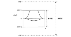
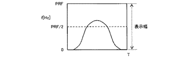
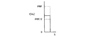
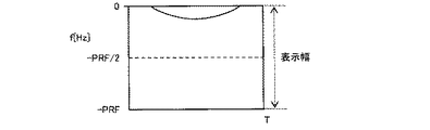
図2は、FFT28eから出力されるドプラスペクトラムの一例を示す模式図である。図3は、図2に示すドプラスペクトラムのベースライン位置をスライドして生成される第1スライド・ドプラスペクトラムを示す模式図である。図4は、図2に示すドプラスペクトラムのSMAPを示す図である。図5は、図4に示すSMAPから信号成分の境界を演算する方法を説明するための図である。図6は、図3に示す第1スライド・ドプラスペクトラムのSMAPを示す図である。図7は、図6に示すSMAPから信号成分の境界を演算する方法を説明するための図である。なお、図2に示すドプラスペクトラムでは、サンプリング周波数として2×PRFを用いるオーバーサンプリング技術を採用しているので、表示幅内に折り返りが存在していない。
FIG. 2 is a schematic diagram illustrating an example of a Doppler spectrum output from the
第1境界検出回路29は、FFT28eから出力されるドプラスペクトラム(図2に図示)のベースライン位置を表示幅の最下端(−Max)までスライドさせ、第1スライド・ドプラスペクトラム(図3に図示)を得る。その結果、FFT28eから出力されるドプラスペクトラムの高周波数側が表示幅に収まっていない(切れている)場合でも、第1スライド・ドプラペクトラムによると最も高周波数側の信号を表示幅内に収めることができる。そして、第1境界検出回路29は、図3に示す第1スライド・ドプラスペクトラムを基に、一周波数軸である閾値以上のパワーの周波数の値が1、閾値以下のパワーの周波数の値が0となるようなsMAPを生成し、sMAPを一定時間範囲の周波数軸に対してそれぞれ行ない、各sMAPを統合(OR)してSMAP(図6に図示)を生成する。なお、SMAPの生成はベースライン位置のスライドに伴って自動的に更新されるようにしてもよい。
The first
例えば、図3に示すような第1スライド・ドプラスペクトラムが生成される場合、第1境界検出回路29は、第1スライド・ドプラスペクトラムを基に、パワーPが閾値Thよりも大きい周波数fについては信号存在領域としての“1”を、小さい周波数fについては信号非存在領域としての“0”をそれぞれ割り当てて、時刻tのsMAPを生成する。第1境界検出回路29は、図3に示す全ての時刻についてsMAPを生成し、それらの結果を統合して、図6に示すようなSMAPを生成する。
For example, when the first slide / Doppler spectrum as shown in FIG. 3 is generated, the first
さらに、第1境界検出回路29は、自身で生成するSMAPを基に、第1スライド・ドプラスペクトラムの表示幅内に信号非存在領域が存在しないと判断する場合、信号非存在領域が存在すると判断するまで第1スライド・ドプラスペクトラムの流速レンジを拡大する。そして、第1境界検出回路29は、信号非存在領域が存在するSMAPを基に、図7に示すような信号存在領域と信号非存在領域との境界(エッジ)E1を信号成分の上限として検出する。なお、境界E1の位置情報は、内部記憶装置34等の記憶装置に記憶される。
Further, when the first
図2に示すドプラスペクトラムを基に生成される図4に示すSMAPによると、図5に示すように、境界の演算においてe1を信号成分の上限と、e2を信号成分の下限と認識してしまう。一方、図3に示すドプラスペクトラムを基に生成される図6に示す各SMAPによると、図7に示すように、正確に適切な信号成分の上限を求めることができる。 According to the SMAP shown in FIG. 4 generated based on the Doppler spectrum shown in FIG. 2, as shown in FIG. 5, e1 is recognized as the upper limit of the signal component and e2 is recognized as the lower limit of the signal component as shown in FIG. . On the other hand, according to each SMAP shown in FIG. 6 generated based on the Doppler spectrum shown in FIG. 3, an upper limit of an appropriate signal component can be accurately obtained as shown in FIG.
次いで、第2境界検出回路30によるSMAPの生成処理について、図2、図4、図5、図8、図9及び図10を用いて説明する。
Next, SMAP generation processing by the second
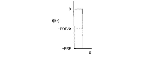
図8は、図2に示すドプラスペクトラムのベースライン位置をスライドして生成される第2スライド・ドプラスペクトラムを示す模式図である。図9は、図8に示す第2スライド・ドプラスペクトラムのSMAPを示す図である。図10は、図9に示すSMAPから信号成分の境界を演算する方法を説明するための図である。 FIG. 8 is a schematic diagram showing a second slide Doppler spectrum generated by sliding the baseline position of the Doppler spectrum shown in FIG. FIG. 9 is a diagram showing the SMAP of the second slide Doppler spectrum shown in FIG. FIG. 10 is a diagram for explaining a method of calculating a boundary between signal components from the SMAP shown in FIG.
第2境界検出回路30は、FFT28eから出力されるドプラスペクトラム(図2に図示)のベースライン位置を表示幅の最上端(+Max)までスライドさせ、第2スライド・ドプラスペクトラム(図8に図示)を得る。その結果、FFT28eから出力されるドプラスペクトラムの低周波数側が表示幅に収まっていない(切れている)場合でも、第2スライド・ドプラペクトラムによると最も低周波数側の信号を表示幅内に収めることができる。そして、第2境界検出回路30は、図8に示す第2スライド・ドプラスペクトラムを基に、一周波数軸である閾値以上のパワーの周波数の値が1、閾値以下のパワーの周波数の値が0となるようなsMAPを生成し、sMAPを一定時間範囲の周波数軸に対してそれぞれ行ない、各sMAPを統合(OR)してSMAP(図9に図示)を生成する。なお、SMAPの生成はベースライン位置のスライドに伴って自動的に更新されるようにしてもよい。
The second
さらに、第2境界検出回路30は、自身で生成するSMAPを基に、第2スライド・ドプラスペクトラムの表示幅内に信号非存在領域が存在しないと判断する場合、信号非存在領域が存在すると判断するまで第2スライド・ドプラスペクトラムの流速レンジを拡大する。そして、第2境界検出回路30は、信号非存在領域が存在するSMAPを基に、図10に示すような信号存在領域と信号非存在領域との境界E2を信号成分の下限として検出する。なお、境界E2の位置情報は、内部記憶装置34等の記憶装置に記憶される。
Further, when the second
図2に示すドプラスペクトラムを基に生成される図4に示すSMAPによると、図5に示すように、境界の演算においてe1を信号成分の上限と、e2を信号成分の下限と認識してしまう。一方、図8に示すドプラスペクトラムを基に生成される図9に示す各SMAPによると、図10に示すように、正確に適切な信号成分の下限を求めることができる。 According to the SMAP shown in FIG. 4 generated based on the Doppler spectrum shown in FIG. 2, as shown in FIG. 5, e1 is recognized as the upper limit of the signal component and e2 is recognized as the lower limit of the signal component as shown in FIG. . On the other hand, according to each SMAP shown in FIG. 9 generated based on the Doppler spectrum shown in FIG. 8, an appropriate lower limit of the signal component can be accurately obtained as shown in FIG.
なお、第1境界検出回路29及び第2境界検出回路30の検出処理の順序は問わないし、また、検出処理は、並列して同時に行なわれるものであってもよい。
The order of the detection processing of the first
ドプラスペクトラム調整回路31は、第1境界検出回路29及び第2境界検出回路30の出力を基に、FFT28eから出力されるドプラスペクトラムを調整する。
The Doppler
具体的には、ドプラスペクトラム調整回路31は、第1境界検出回路29から出力される境界E1の位置情報と、第2境界検出回路30から出力される境界E2の位置情報との差を基に、信号非存在領域の大きさを演算する。そして、ドプラスペクトラム調整回路31は、信号非存在領域の大きさが、予め設定される期待値(閾値)となるように、FFT28eから出力されるドプラスペクトラムの流速レンジを調整する。また、ドプラスペクトラム調整回路31は、境界E1と境界E2との差を基に信号非存在領域の中心を求め、その中心が両端となるようにドプラスペクトラムを調整する。
Specifically, the Doppler
なお、第1境界検出回路29及び第2境界検出回路30による動作中、必ずしもドプラスペクトラムを表示させる必要はなく装置内部のバックグランドの処理として対応してもよい。
During the operation by the first
表示画像生成回路32は、DSC(digital scan converter)及びD/A(digital to analog)変換回路等によって構成される。表示画像生成回路32は、Bモード画像生成回路22の出力信号及びドプラスペクトラム調整回路31の出力信号を基に、Bモード画像と並列にドプラスペクトラムが分割表示される表示画像を生成し、ディスプレイ13に出力する。これにより、ディスプレイ13上に、Bモード画像及びドプラスペクトラムが表示される。
The display
ディスプレイ13は、CRT(cathode ray tube)等によって構成される。表示画像生成回路32から出力される表示画像を表示する。
The
操作パネル14は、トラックボール、各種スイッチ、ボタン、マウス及びキーボード等によって構成される。操作パネル14は、装置本体12のIF35に接続され、ユーザ(操作者)からの各種指示、例えば、関心領域(ROI:region of interest)の設定指示、画質条件設定指示、レンジゲート位置信号及びフリーズ指令信号をIF35に出力する。
The
CPU33は、半導体で構成された電子回路が複数の端子を持つパッケージに封入されている集積回路(LSI)の構成をもつ制御装置である。CPU33は、内部記憶装置34に記憶しているプログラムを実行する機能を有する。又は、CPU33は、外部記憶装置36に記憶しているプログラム等を、内部記憶装置34にロードして実行する。
The
内部記憶装置34は、ROM(read only memory)及びRAM(random access memory)等の要素を兼ね備える構成をもつ記憶装置である。内部記憶装置34は、IPL(initial program loading)、BIOS(basic input/output system)及びデータを記憶したり、CPU25のワークメモリやデータの一時的な記憶に用いたりする。
The internal storage device 34 is a storage device having a configuration that combines elements such as a read only memory (ROM) and a random access memory (RAM). The internal storage device 34 stores IPL (initial program loading), BIOS (basic input / output system), and data, and is used for temporary storage of the work memory and data of the
IF35は、パラレル接続仕様やシリアル接続仕様に合わせたコネクタによって構成される。IF35は、操作パネル14及び外部記憶装置36等に関するインターフェースである。
The
外部記憶装置36は、磁性体を塗布又は蒸着した金属のディスクが読み取り装置(図示しない)に着脱不能で内蔵されている構成をもつ記憶装置である。外部記憶装置36は、装置本体12にインストールされたプログラム(アプリケーションプログラムの他、OS(operating system)等も含まれる)を記憶する。また、OSに、ユーザに対する情報の表示にグラフィックを多用し、基礎的な操作を操作パネル15によって行なうことができるGUI(graphical user interface)を提供させることもできる。
The external storage device 36 is a storage device having a configuration in which a metal disk coated or vapor-deposited with a magnetic material is incorporated in a reading device (not shown) in a non-detachable manner. The external storage device 36 stores a program (including an OS (operating system) in addition to an application program) installed in the apparatus
続いて、本実施形態の超音波ドプラ診断装置10の動作について、図11に示すフローチャートを用いて説明する。
Next, the operation of the ultrasonic Doppler
超音波ドプラ診断装置10が起動されると、装置本体12は、基準信号発生回路21aから出力されるレートパルスによって、超音波プローブ11の圧電振動子群を励振し、超音波信号が患者P内に送波される。送波される超音波信号は患者Pの各部で反射し、そのエコー信号が超音波プローブ11の圧電振動子群によって受信される。エコー信号は圧電振動子群によって電気信号に変換され、その電気信号は装置本体12の加算回路21eによって受信フォーカスが掛けられる。加算回路21eから出力される指定ラスタアドレスの信号のうち一方は、Bモード画像生成回路22に出力され、対数増幅処理・包絡線検波処理が施され、指定ラスタアドレスの画像信号に検波・変換される。Bモード画像を形成する画像信号は表示画像生成回路32に出力される。
When the ultrasonic Doppler
一方、送受信部21の加算回路21eの出力信号は、位相検波用のミキサ24を介してLPF25にも出力される。また、基準信号発生回路21aの出力信号は、ミキサ24の一方のチャンネルに直接出力され、90度移相器26を介してミキサ24の他方のチャンネルに接続されている。このため、装置本体12によって整相加算されるエコー信号がミキサ24に加えられる他、基準信号発生回路21aからの基準信号f0及び90度の位相差をもった基準信号f0がミキサ24の2チャンネルにそれぞれ加えられる。これにより、ミキサ24はドプラ偏移信号fdと「2f0+fd」の信号をLPF25に出力する。
On the other hand, the output signal of the
ミキサ24からの混合信号の中から高周波成分がLPF25によって除去され、ドプラ偏移信号fdのみが得られる。ドプラ偏移信号fdは、血流情報に演算するための位相検波出力であり、ドプラスペクトラム演算部28に出力される。
High-frequency components from the mixed signal from the
また、基準信号発生回路21aによって発生される基準信号と、CPU33から出力されるサンプリング周波数(2×PRF)とを基に、サンプリングパルス発生回路27によってサンプリングパルスが発生される。
A sampling pulse is generated by the sampling
次いで、LPF25及びサンプリングパルス発生回路27の出力を基に、ドプラスペクトラム演算部28によって解析結果としてのドプラスペクトラムが演算される。
Next, based on the outputs of the
次いで、FFT28eから出力されるドプラスペクトラム(図2に図示)のベースライン位置が表示幅の最下端(−Max)までスライドされ(ステップS1)、第1スライド・ドプラスペクトラム(図3に図示)が得られる。その結果、FFT28eから出力されるドプラスペクトラムの高周波数側が表示幅に収まっていない(切れている)場合でも、第1スライド・ドプラペクトラムによると最も高周波数側の信号を表示幅内に収めることができる。そして、図3に示す第1スライド・ドプラスペクトラムを基に、SMAP(図6に図示)が生成される(ステップS2)。
Next, the base line position of the Doppler spectrum (shown in FIG. 2) output from the
次いで、ステップS2によって生成されるSMAPを基に、第1スライド・ドプラスペクトラムの表示幅内に信号非存在領域が存在するか否かが判断される(ステップS3)。ステップS3によってNO、すなわち、信号非存在領域が存在しないと判断される場合、信号非存在領域が存在すると判断されるまで第1スライド・ドプラスペクトラムの流速レンジが拡大される(ステップS4)。一方、ステップS3によってYES、すなわち、信号非存在領域が存在すると判断される場合、信号非存在領域が存在するSMAPを基に、信号存在領域と信号非存在領域との境界E1が信号成分の上限として求められる(ステップS5)。なお、境界E1の位置情報は、内部記憶装置34等の記憶装置に記憶される。 Next, based on the SMAP generated in step S2, it is determined whether or not there is a signal non-existing region within the display width of the first slide / Doppler spectrum (step S3). If NO in step S3, that is, if it is determined that there is no signal nonexistence region, the flow velocity range of the first slide Doppler spectrum is expanded until it is determined that there is no signal nonexistence region (step S4). On the other hand, if YES in step S3, that is, if it is determined that a signal non-existing area exists, the boundary E1 between the signal existing area and the signal non-existing area is based on the SMAP where the signal non-existing area exists. (Step S5). The position information of the boundary E1 is stored in a storage device such as the internal storage device 34.
次いで、FFT28eから出力されるドプラスペクトラム(図2に図示)のベースライン位置が表示幅の最上端(+Max)までスライドされ(ステップS6)、第2スライド・ドプラスペクトラム(図8に図示)が得られる。その結果、FFT28eから出力されるドプラスペクトラムの低周波数側が表示幅に収まっていない(切れている)場合でも、第2スライド・ドプラペクトラムによると最も低周波数側の信号を表示幅内に収めることができる。そして、図8に示す第2スライド・ドプラスペクトラムを基に、SMAP(図9に図示)が生成される(ステップS7)。
Next, the base line position of the Doppler spectrum (shown in FIG. 2) output from the
次いで、ステップS7によって生成されるSMAPを基に、第2スライド・ドプラスペクトラムの表示幅内に信号非存在領域が存在するか否かが判断される(ステップS8)。ステップS8によってNO、すなわち、信号非存在領域が存在しないと判断される場合、信号非存在領域が存在すると判断されるまで第2スライド・ドプラスペクトラムの流速レンジが拡大される(ステップS9)。一方、ステップS8によってYES、すなわち、信号非存在領域が存在すると判断される場合、信号非存在領域が存在するSMAPを基に、信号存在領域と信号非存在領域との境界E2が信号成分の下限として求められる(ステップS10)。なお、境界E2の位置情報は、内部記憶装置34等の記憶装置に記憶される。 Next, based on the SMAP generated in step S7, it is determined whether or not there is a signal non-existing region within the display width of the second slide Doppler spectrum (step S8). If NO in step S8, that is, if it is determined that there is no signal nonexistence region, the flow velocity range of the second slide Doppler spectrum is expanded until it is determined that there is no signal nonexistence region (step S9). On the other hand, if YES in step S8, that is, if it is determined that a signal non-existing area exists, the boundary E2 between the signal existing area and the signal non-existing area is based on the SMAP where the signal non-existing area exists. (Step S10). The position information of the boundary E2 is stored in a storage device such as the internal storage device 34.
次いで、ステップS5によって算出される境界E1の位置情報と、ステップS10によって算出される境界E2の位置情報との差を基に、信号非存在領域の大きさを演算する(ステップS11)。そして、ステップS11によって算出される信号非存在領域の大きさが、予め設定される期待値(閾値)になるように、FFT28eから出力されるドプラスペクトラムの流速レンジが調整される(ステップS12)。次いで、ステップS11によって算出される境界E1と境界E2との差を基に信号非存在領域の中心が求められ、その中心が両端となるようにドプラスペクトラムが調整される(ステップS13)。
Next, the size of the signal non-existing region is calculated based on the difference between the position information of the boundary E1 calculated in step S5 and the position information of the boundary E2 calculated in step S10 (step S11). Then, the flow velocity range of the Doppler spectrum output from the
本実施形態の超音波ドプラ診断装置10によると、サンプリング周波数を遮蔽周波数(PRF)の2倍以上に設定するオーバーサンプリング技術によって、ドプラ信号が折り返し表示されない状態であっても、流速レンジやベースライン位置の自動調整機能が適切に動作するので、操作者とって常に適切なドプラ信号の波形を提示することができる。
According to the ultrasonic Doppler
10 超音波ドプラ診断装置
11 超音波プローブ
13 ディスプレイ
14 操作パネル
21 送受信部
22 Bモード画像生成回路
28 ドプラスペクトラム演算部
29 第1境界検出回路
30 第2境界検出回路
31 ドプラスペクトラム調整回路
32 表示画像生成回路
DESCRIPTION OF
Claims (5)
前記送受信手段によって得られる受信信号を帯域制限フィルタの遮蔽周波数の2倍以上の周波数でサンプリングして前記運動体に起因するドプラ信号を抽出する抽出手段と、
前記抽出手段によって抽出されるドプラ信号を基にドプラ偏移周波数を分析してドプラスペクトラムを生成する手段と、
前記ドプラスペクトラムの正の最大を含む第1ドプラスペクトラムを生成し、前記第1ドプラスペクトラムを基に、信号存在領域と信号非存在領域との第1境界を検出し、前記ドプラスペクトラムの負の最大を含む第2ドプラスペクトラムを生成し、前記第2ドプラスペクトラムを基に、信号存在領域と信号非存在領域との第2境界を検出する検出手段と、
前記第1境界と前記第2境界との差を基に、前記ドプラスペクトラムの表示体系を調整する調整手段と、
前記調整後のドプラスペクトラムをディスプレイ上に表示させる手段と、
を有することを特徴とする超音波ドプラ診断装置。 Transmitting and receiving means for transmitting and receiving ultrasonic waves to and from a diagnostic site including a moving body in a subject;
Sampling means for sampling a reception signal obtained by the transmission / reception means at a frequency that is twice or more the shielding frequency of a band limiting filter to extract a Doppler signal caused by the moving body;
Means for analyzing a Doppler shift frequency based on the Doppler signal extracted by the extraction means to generate a Doppler spectrum;
Generating a first de plug spectrum containing positive maximum of the Doppler spectrum, based on the first de plug spectrum, detecting a first boundary between the signal existence region and the signal absence regions, the negative of the Doppler spectrum up generates the second de plug spectrum containing the, on the basis of the second de-plug spectrum and detection means that detect a second boundary between the signal existence region and the signal absence regions,
Adjusting means for adjusting a display system of the Doppler spectrum based on a difference between the first boundary and the second boundary;
Means for displaying the adjusted Doppler spectrum on a display;
An ultrasonic Doppler diagnostic apparatus comprising:
Priority Applications (1)
| Application Number | Priority Date | Filing Date | Title |
|---|---|---|---|
| JP2008146189A JP5259259B2 (en) | 2008-06-03 | 2008-06-03 | Ultrasonic Doppler diagnostic device |
Applications Claiming Priority (1)
| Application Number | Priority Date | Filing Date | Title |
|---|---|---|---|
| JP2008146189A JP5259259B2 (en) | 2008-06-03 | 2008-06-03 | Ultrasonic Doppler diagnostic device |
Publications (2)
| Publication Number | Publication Date |
|---|---|
| JP2009291325A JP2009291325A (en) | 2009-12-17 |
| JP5259259B2 true JP5259259B2 (en) | 2013-08-07 |
Family
ID=41540080
Family Applications (1)
| Application Number | Title | Priority Date | Filing Date |
|---|---|---|---|
| JP2008146189A Expired - Fee Related JP5259259B2 (en) | 2008-06-03 | 2008-06-03 | Ultrasonic Doppler diagnostic device |
Country Status (1)
| Country | Link |
|---|---|
| JP (1) | JP5259259B2 (en) |
Families Citing this family (3)
| Publication number | Priority date | Publication date | Assignee | Title |
|---|---|---|---|---|
| US7804736B2 (en) * | 2006-03-30 | 2010-09-28 | Aloka Co., Ltd. | Delay controller for ultrasound receive beamformer |
| JP5438066B2 (en) * | 2011-05-25 | 2014-03-12 | 日立アロカメディカル株式会社 | Ultrasonic image processing apparatus and program |
| US10575825B2 (en) | 2015-07-27 | 2020-03-03 | Siemens Medical Solutions Usa, Inc. | Doppler imaging |
Family Cites Families (14)
| Publication number | Priority date | Publication date | Assignee | Title |
|---|---|---|---|---|
| JPS63154164A (en) * | 1986-12-18 | 1988-06-27 | 富士通株式会社 | Ultrasonic cw doppler blood flowmeter |
| JP2693575B2 (en) * | 1989-05-24 | 1997-12-24 | 株式会社東芝 | Ultrasonic Doppler blood flow measurement device |
| JPH0723952A (en) * | 1993-07-12 | 1995-01-27 | Toshiba Corp | Ultrasonic Doppler diagnostic device |
| JP3698173B2 (en) * | 1995-05-24 | 2005-09-21 | 東芝医用システムエンジニアリング株式会社 | Ultrasonic diagnostic equipment |
| JPH1014918A (en) * | 1996-06-28 | 1998-01-20 | Shimadzu Corp | Ultrasound diagnostic equipment |
| JPH11113911A (en) * | 1997-10-17 | 1999-04-27 | Fuji Electric Co Ltd | Ultrasound Doppler diagnostic device |
| JP2002143157A (en) * | 2000-11-09 | 2002-05-21 | Fukuda Denshi Co Ltd | Ultrasound diagnostic equipment |
| JP2003079624A (en) * | 2001-09-14 | 2003-03-18 | Ge Medical Systems Global Technology Co Llc | Doppler sound generation method and ultrasonic diagnostic apparatus |
| US6663566B2 (en) * | 2002-02-19 | 2003-12-16 | Ge Medical Systems Global Technology Company, Llc | Method and apparatus for automatic control of spectral doppler imaging |
| JP2004089309A (en) * | 2002-08-30 | 2004-03-25 | Hitachi Medical Corp | Ultrasonic diagnostic device |
| JP4568080B2 (en) * | 2004-10-21 | 2010-10-27 | 株式会社東芝 | Ultrasonic diagnostic equipment |
| JP2006149603A (en) * | 2004-11-29 | 2006-06-15 | Toshiba Corp | Ultrasound diagnostic imaging equipment |
| JP2007202617A (en) * | 2006-01-31 | 2007-08-16 | Toshiba Corp | Ultrasonic diagnostic equipment |
| JP5342104B2 (en) * | 2006-10-30 | 2013-11-13 | 株式会社東芝 | Ultrasonic diagnostic apparatus and image processing program |
-
2008
- 2008-06-03 JP JP2008146189A patent/JP5259259B2/en not_active Expired - Fee Related
Also Published As
| Publication number | Publication date |
|---|---|
| JP2009291325A (en) | 2009-12-17 |
Similar Documents
| Publication | Publication Date | Title |
|---|---|---|
| US9895138B2 (en) | Ultrasonic diagnostic apparatus | |
| JP6013051B2 (en) | Ultrasonic diagnostic apparatus and operation support method thereof | |
| JP7295296B2 (en) | ULTRASOUND DIAGNOSTIC SYSTEM AND CONTROL METHOD OF ULTRASOUND DIAGNOSTIC SYSTEM | |
| JP5025400B2 (en) | Ultrasonic diagnostic apparatus and ultrasonic image processing apparatus | |
| US20150282787A1 (en) | Ultrasound diagnostic apparatus, image processing device, and image processing method | |
| JP2006187594A (en) | Ultrasound diagnostic system and method | |
| JPH03188841A (en) | Ultrasonic diagnostic device | |
| JP5054361B2 (en) | Automatic adjustment of spectral Doppler gain in ultrasound systems | |
| WO2014013839A1 (en) | Ultrasonic diagnostic device and image processing device | |
| JP3698173B2 (en) | Ultrasonic diagnostic equipment | |
| JPH06327672A (en) | Ultrasonic Doppler diagnostic device | |
| JP5259259B2 (en) | Ultrasonic Doppler diagnostic device | |
| JP6413616B2 (en) | Ultrasonic diagnostic apparatus, controller for ultrasonic diagnostic apparatus, and control method for ultrasonic diagnostic apparatus | |
| JP2006167100A (en) | Ultrasonic diagnostic equipment | |
| JP5455567B2 (en) | Ultrasonic diagnostic equipment | |
| JP2000166926A (en) | Ultrasound diagnostic imaging device | |
| JP5342104B2 (en) | Ultrasonic diagnostic apparatus and image processing program | |
| JP7645692B2 (en) | Ultrasound diagnostic equipment and medical analysis equipment | |
| JP5578756B2 (en) | Ultrasonic Doppler diagnostic device | |
| JP2010274068A (en) | Ultrasonic diagnostic apparatus and image display method in ultrasonic diagnostic apparatus | |
| JP2003135466A (en) | Ultrasonic diagnostic instrument | |
| US20230404535A1 (en) | Ultrasonic diagnostic apparatus, method for controlling ultrasonic diagnostic apparatus, and control program for ultrasonic diagnostic apparatus | |
| JP4568080B2 (en) | Ultrasonic diagnostic equipment | |
| US12059305B2 (en) | Ultrasonic diagnostic device, medical image processing device, and medical image processing method | |
| JPH07236640A (en) | Ultrasonic diagnostic equipment |
Legal Events
| Date | Code | Title | Description |
|---|---|---|---|
| RD04 | Notification of resignation of power of attorney |
Free format text: JAPANESE INTERMEDIATE CODE: A7424 Effective date: 20100422 |
|
| A621 | Written request for application examination |
Free format text: JAPANESE INTERMEDIATE CODE: A621 Effective date: 20110601 |
|
| RD01 | Notification of change of attorney |
Free format text: JAPANESE INTERMEDIATE CODE: A7421 Effective date: 20111206 |
|
| A977 | Report on retrieval |
Free format text: JAPANESE INTERMEDIATE CODE: A971007 Effective date: 20121221 |
|
| A131 | Notification of reasons for refusal |
Free format text: JAPANESE INTERMEDIATE CODE: A131 Effective date: 20130108 |
|
| A521 | Request for written amendment filed |
Free format text: JAPANESE INTERMEDIATE CODE: A523 Effective date: 20130311 |
|
| TRDD | Decision of grant or rejection written | ||
| A01 | Written decision to grant a patent or to grant a registration (utility model) |
Free format text: JAPANESE INTERMEDIATE CODE: A01 Effective date: 20130402 |
|
| A61 | First payment of annual fees (during grant procedure) |
Free format text: JAPANESE INTERMEDIATE CODE: A61 Effective date: 20130424 |
|
| FPAY | Renewal fee payment (event date is renewal date of database) |
Free format text: PAYMENT UNTIL: 20160502 Year of fee payment: 3 |
|
| R150 | Certificate of patent or registration of utility model |
Ref document number: 5259259 Country of ref document: JP Free format text: JAPANESE INTERMEDIATE CODE: R150 Free format text: JAPANESE INTERMEDIATE CODE: R150 |
|
| S111 | Request for change of ownership or part of ownership |
Free format text: JAPANESE INTERMEDIATE CODE: R313117 |
|
| R350 | Written notification of registration of transfer |
Free format text: JAPANESE INTERMEDIATE CODE: R350 |
|
| S533 | Written request for registration of change of name |
Free format text: JAPANESE INTERMEDIATE CODE: R313533 |
|
| R350 | Written notification of registration of transfer |
Free format text: JAPANESE INTERMEDIATE CODE: R350 |
|
| LAPS | Cancellation because of no payment of annual fees |