JP5259158B2 - Endoscope cleaning disinfection device - Google Patents
Endoscope cleaning disinfection device Download PDFInfo
- Publication number
- JP5259158B2 JP5259158B2 JP2007294594A JP2007294594A JP5259158B2 JP 5259158 B2 JP5259158 B2 JP 5259158B2 JP 2007294594 A JP2007294594 A JP 2007294594A JP 2007294594 A JP2007294594 A JP 2007294594A JP 5259158 B2 JP5259158 B2 JP 5259158B2
- Authority
- JP
- Japan
- Prior art keywords
- endoscope
- unit
- temperature
- cleaning
- disinfecting
- Prior art date
- Legal status (The legal status is an assumption and is not a legal conclusion. Google has not performed a legal analysis and makes no representation as to the accuracy of the status listed.)
- Expired - Fee Related
Links
Images


Landscapes
- Endoscopes (AREA)
- Apparatus For Disinfection Or Sterilisation (AREA)
Description
本発明は、内視鏡洗浄消毒装置に関し、特に、消毒用として使用される薬液を、使用前に予め加温しておくことが可能な内視鏡洗浄消毒装置に関するものである。 The present invention relates to an endoscope cleaning / disinfecting apparatus, and more particularly to an endoscope cleaning / disinfecting apparatus capable of preheating a chemical solution used for disinfecting before use.
内視鏡は、工業分野及び医療分野等において従来広く用いられている。特に、医療分野における内視鏡は、生体内の各種器官に対する観察等を行う際に主に用いられている。 Endoscopes have been widely used in the industrial and medical fields. In particular, endoscopes in the medical field are mainly used when observing various organs in a living body.
医療分野における内視鏡は、体腔内に挿入して使用されるとともに、例えば、該体腔内の患部に対して吹きつける気体または液体を流通させるための送気送水チャンネル、及び、該体腔内の患部に対して処置を行うための処置具を挿通可能な処置具チャンネル等の複数の管路を有して構成されている。そのため、医療分野における内視鏡は、使用後において、外装表面のみならず、前記複数の管路内に至るまで十分に洗浄及び消毒される必要がある。 Endoscopes in the medical field are used by being inserted into body cavities, for example, an air / water supply channel for circulating a gas or a liquid to be blown against an affected part in the body cavity, It has a plurality of conduits such as a treatment instrument channel through which a treatment instrument for performing treatment on the affected part can be inserted. Therefore, an endoscope in the medical field needs to be sufficiently cleaned and disinfected after use until it reaches not only the exterior surface but also the plurality of ducts.
そして、医療分野における内視鏡を洗浄及び消毒するための装置としては、例えば、特許文献1、特許文献2及び特許文献3に提案されているものがある。
And as an apparatus for cleaning and disinfecting an endoscope in the medical field, for example, there are those proposed in
特許文献1には、消毒液タンクの底面に設けられたラバーヒータの発熱を制御することにより、該消毒液タンク内の薬液の温度調整を行うことが可能な構成を有する内視鏡洗浄消毒装置が提案されている。
また、特許文献2及び特許文献3には、消毒液タンク内の薬液をヒータにより加温可能な、前述した特許文献1の構成に対して類似の構成を有する内視鏡洗浄消毒装置が提案されている。
内視鏡洗浄消毒装置が有する各部のうち、内視鏡が配置される洗浄槽は、一般的に、周囲の気温変化の影響を受けやすい部分である。 Of each part of the endoscope cleaning / disinfecting apparatus, the cleaning tank in which the endoscope is arranged is generally a part that is easily affected by ambient temperature changes.
そのため、例えば周囲の気温が低い場所に内視鏡洗浄消毒装置が配置された場合、消毒液タンク内の薬液が予め加温された状態として洗浄消毒槽(以降、洗浄槽と略記する)へ排出されたとしても、該洗浄槽の内部の温度に応じて該薬液の温度が低下し、結果的に、該洗浄槽に溜められた該薬液の温度が内視鏡の消毒に適した温度に到達しないまま消毒工程が開始されてしまう、という課題が生じている。そして、特許文献1、特許文献2及び特許文献3のいずれにおいても、前述した課題に対する言及がなされていない。
Therefore, for example, when an endoscope cleaning / disinfecting device is arranged in a place where the ambient temperature is low, the chemical solution in the disinfecting solution tank is discharged into a cleaning / disinfecting tank (hereinafter abbreviated as a cleaning tank) in a preheated state. Even if the temperature of the chemical solution is reduced, the temperature of the chemical solution decreases according to the temperature inside the cleaning bath, and as a result, the temperature of the chemical solution stored in the cleaning bath reaches a temperature suitable for disinfection of the endoscope. There is a problem that the disinfection process is started without doing so. In any of
本発明は、前述した事情に鑑みてなされたものであり、洗浄槽に溜められる薬液の温度を適温とすることにより、確実な消毒効果を得ることができる内視鏡洗浄消毒装置を提供することを目的としている。 The present invention has been made in view of the above-described circumstances, and provides an endoscope cleaning / disinfecting apparatus that can obtain a reliable disinfecting effect by setting the temperature of a chemical solution stored in a cleaning tank to an appropriate temperature. It is an object.
本発明の一態様の内視鏡洗浄消毒装置は、内視鏡を浸漬可能な深さを有する内視鏡配置部と、前記内視鏡配置部の内部の温度を計測する第1の温度計測部と、前記内視鏡配置部において前記内視鏡の消毒を行うための薬液が貯蔵された貯蔵部と、前記貯蔵部に貯蔵された前記薬液の温度を計測する第2の温度計測部と、前記貯蔵部に貯蔵された前記薬液を加温する加温部と、前記第1の温度計測部における第1の計測結果及び前記第2の温度計測部における第2の計測結果を取得し、前記第1の計測結果及び前記第2の計測結果に基づき、前記貯蔵部に貯蔵された前記薬液の温度が、前記内視鏡配置部へ前記薬液が供給される事前に取得した前記第1の計測結果と、前記薬液が最大の消毒効果を呈する温度と、に基づいて算出される所定の到達目標温度に達するまで前記薬液を加温させるための制御を、前記内視鏡配置部へ前記薬液が供給される以前の期間に前記加温部に対して行う制御部と、を有する。 An endoscope cleaning / disinfecting apparatus according to an aspect of the present invention includes an endoscope arrangement unit having a depth capable of immersing the endoscope, and a first temperature measurement for measuring a temperature inside the endoscope arrangement unit. A storage unit storing a chemical for disinfecting the endoscope in the endoscope arrangement unit, and a second temperature measurement unit measuring the temperature of the chemical stored in the storage unit A heating unit for heating the chemical stored in the storage unit, a first measurement result in the first temperature measurement unit, and a second measurement result in the second temperature measurement unit, Based on the first measurement result and the second measurement result, the temperature of the medicinal solution stored in the storage unit is acquired in advance before the medicinal solution is supplied to the endoscope arrangement unit. the measurement result, and the temperature exhibiting the disinfecting effect of the chemical is maximum, the predetermined calculated based on the arrival The control for warmed to the drug solution to reach the target temperature, the chemical into the endoscope disposed portion that have a, and a control unit which performs relative to the heating unit to the previous periods supplied.
本発明における内視鏡洗浄消毒装置によると、洗浄槽に溜められる薬液の温度を適温とすることにより、確実な消毒効果を得ることができる。 According to the endoscope cleaning / disinfecting apparatus of the present invention, a reliable disinfecting effect can be obtained by setting the temperature of the chemical solution stored in the cleaning tank to an appropriate temperature.
以下、図面を参照して本発明の実施の形態を説明する。 Embodiments of the present invention will be described below with reference to the drawings.
図1から図9は、本発明の実施形態に係るものである。図1は、本発明の実施形態に係る内視鏡洗浄消毒装置の構成の一例を示す図である。図2は、図1の内視鏡洗浄消毒装置における装置本体の内部構成の一例を示す図である。図3は、図2のCPUにより行われる制御の概要を示すブロック図である。図4は、ヒータ等における出力状態の遷移を示すタイムチャートである。図5は、図2のCPUにより行われるヒータ制御の一例を示すフローチャートである。図6は、内視鏡洗浄消毒装置の使用開始時刻に関する予約設定を行うための設定画面の一例を示す図である。図7は、図6における「予約設定」スイッチが押されることにより遷移した後の画面であり、かつ、予約設定が未設定である場合の画面の一例を示す図である。図8は、図7の画面内における日時の入力が完了した場合の画面の一例を示す図である。図9は、内視鏡洗浄消毒装置の使用開始時刻に関する予約設定が行われた場合の処理の一例を示す処理フローである。 1 to 9 relate to an embodiment of the present invention. FIG. 1 is a diagram illustrating an example of a configuration of an endoscope cleaning / disinfecting apparatus according to an embodiment of the present invention. FIG. 2 is a diagram illustrating an example of an internal configuration of the apparatus main body in the endoscope cleaning / disinfecting apparatus of FIG. FIG. 3 is a block diagram showing an outline of the control performed by the CPU of FIG. FIG. 4 is a time chart showing transition of the output state in the heater or the like. FIG. 5 is a flowchart showing an example of heater control performed by the CPU of FIG. FIG. 6 is a diagram illustrating an example of a setting screen for performing a reservation setting regarding the use start time of the endoscope cleaning / disinfecting apparatus. FIG. 7 is a diagram showing an example of a screen after transition is made by pressing the “reservation setting” switch in FIG. 6 and when the reservation setting is not set. FIG. 8 is a diagram showing an example of the screen when the date and time input is completed in the screen of FIG. FIG. 9 is a process flow illustrating an example of a process when a reservation setting regarding the use start time of the endoscope cleaning / disinfecting apparatus is performed.
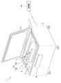
内視鏡洗浄消毒装置1は、図1に示すように、全体に略直方体形状をした装置本体2と、装置本体2の上面を覆うトップカバー3とを有する。また、装置本体2は、例えばパーソナルコンピュータ等からなる端末装置201と、ネットワークを介して通信(接続)可能な構成を有している。
As shown in FIG. 1, the endoscope cleaning / disinfecting
洗浄槽カバーとしてのトップカバー3は、装置本体2の上面に対してヒンジ機構(図示せず)により開閉可能なように取り付けられている。
A
装置本体2の上面には、内視鏡101を収納可能であるとともに、内視鏡101を浸漬可能な程度の深さを有する洗浄槽4が設けられている。洗浄槽4内に収納された内視鏡101は、トップカバー3が装置本体2の洗浄槽4を覆うように閉じられた状態において、所定の洗浄工程及び消毒工程に従って、洗浄と消毒が行われる。また、装置本体2の前面には、主電源オン/オフ、洗浄開始及び洗浄停止等の各種機能を設定指示できるとともに、表示機能を備えた操作パネル8が設けられている。
On the upper surface of the apparatus
内視鏡101は、可撓性を有する挿入部102と、操作部103とからなる。そして、内視鏡101は、例えば、挿入部102が曲げられ、かつ、操作部103が複数のピン4aの間に位置決めされた状態として、洗浄槽4内に収納される。また、位置決めされた状態の操作部103の近傍には、洗浄槽4の壁面において露呈した管路接続ユニット5が設けられている。なお、本実施形態においては、操作部103を位置決めするためのピン4aが洗浄槽4に設けられたものに限らず、挿入部102を所定の形状として位置決めするための他のピンが洗浄槽4に設けられたものであっても良い。
The
管路接続ユニット5は、洗浄液等が供給される接続管を、内視鏡101の操作部103に設けられた、送気送水チャンネル及び処置具チャンネル等の各種管路の開口部に(自動的に)接続するための機構を有している。
The
内視鏡配置部としての洗浄槽4の壁面または底面には、管路接続ユニット5に加え、装置本体2に内蔵された消毒液タンクからの消毒液が排出される消毒液供給口6、及び、洗浄槽4の内部の温度を計測する温度センサ7がさらに設けられている。
On the wall surface or bottom surface of the
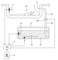
装置本体2の内部には、図2に示すように、各種制御を行うCPU11と、貯蔵部としての消毒液タンク12と、消毒液供給口6と消毒液タンク12との間を接続する管路12aと、管路12aの途中に設けられたポンプ12bと、が設けられている。また、消毒液タンク12の内部には、消毒液タンク12に貯蔵された消毒液13の温度を計測する温度センサ14と、CPU11の制御に応じて発熱状態を変化させるヒータ15と、が設けられている。
As shown in FIG. 2, in the apparatus
ポンプ12bは、CPU11の制御に基づいて動作することにより、消毒液タンク12に貯蔵された消毒液13の洗浄槽4への供給を開始または停止する。
The
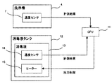
制御部としてのCPU11は、温度センサ7により計測された洗浄槽4の内部の温度と、温度センサ14により計測された消毒液13の温度とに基づき、加温部としてのヒータ15における出力の制御を行う。なお、図3は、CPU11により行われる制御の概要を示すブロック図である。また、CPU11は、操作パネル8の操作に応じて出力される指示に基づく制御を、装置本体2の各部に対して行う。
The
次に、内視鏡洗浄消毒装置1の作用について説明を行う。
Next, the operation of the endoscope cleaning / disinfecting
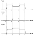
まず、操作パネル8の操作により主電源がオンに切り替えられると、図4の時刻t1に相当するタイミングにおいて、装置本体2の各部が動作を開始する。
First, when the main power supply is switched on by operating the
CPU11は、図4の時刻t1に相当するタイミングにおいて起動した後、例えば、ヒータ15を略最大の出力である第1の出力により発熱させるとともに、該第1の出力を保持するモードである、加温モードに遷移させるための制御をヒータ15に対して行う(図5のステップS1)。これにより、時間の経過に伴って消毒液13が加温される。
After starting at the timing corresponding to time t1 in FIG. 4, for example, the
そして、内視鏡101が洗浄槽4にセットされた後、操作パネル8の操作により、図4の時刻t2に相当するタイミングにおいて洗浄開始の指示がなされると、CPU11は、内視鏡101の外装表面及び内視鏡101に設けられた各種管路等の洗浄を行う工程である、洗浄工程を開始させるための制御を行う(図5のステップS2)。
Then, after the
また、CPU11は、図4の時刻t2に相当するタイミングにおいて、例えば、前述した第1の出力に比べて数十パーセント程度低い出力である第2の出力により発熱させるとともに、該第2の出力を保持するモードである、保温モードに遷移させるための制御をヒータ15に対して行う(図5のステップS3)。
In addition, at the timing corresponding to time t2 in FIG. 4, for example, the
図4の時刻t2に相当するタイミングから時刻t3に相当するタイミングまでの期間として示される、洗浄工程の期間においては、例えば、ヒータ15のみならず、装置本体2に設けられたポンプ等も動作するため、内視鏡洗浄消毒装置1の合計出力が一時的に極端に大きくなってしまう傾向がある。そこで、本実施形態における内視鏡洗浄消毒装置1は、前述した洗浄工程の期間中のヒータ15の出力を保温モードとして保持することにより、合計出力の極端な上昇を抑えることができるとともに、消毒工程開始直前における消毒液13の加温時間を短縮することができる。
In the period of the cleaning process, which is shown as a period from the timing corresponding to time t2 in FIG. 4 to the timing corresponding to time t3, for example, not only the
一方、CPU11は、図4の時刻t3に相当するタイミングにおいて、洗浄工程が終了したことを検知する(図5のステップS4)と、温度センサ7により計測された洗浄槽4の内部の温度を取得する(図5のステップS5)。そして、CPU11は、図5のステップS5の処理において取得した洗浄槽4の内部の温度と、例えば図示しないメモリ等に書き込まれたテーブルデータとに基づき、消毒液13の到達目標温度Taを算出する(図5のステップS6)。なお、前記テーブルデータは、例えば、消毒液13が最大の消毒効果を呈する温度Tcと、前記到達目標温度Taとの相関が示されたデータとして構成されているものとする。
On the other hand, when the
その後、CPU11は、温度センサ14により計測された消毒液13の温度Tbを取得しつつ(図5のステップS7)、温度Tbが到達目標温度Taを超えているか否かの判定を行う(図5のステップS8)。
Thereafter, the
CPU11は、図5のステップS8の処理において、温度Tbが到達目標温度Taを超えていないことを検出した場合、ヒータ15を加温モードに遷移させるための制御を行った(図5のステップS9)後、温度センサ14により計測された消毒液13の温度Tbを再度取得しつつ(図5のステップS7)、温度Tbが到達目標温度Taを超えているか否かの判定を再度行う(図5のステップS8)。
When the
すなわち、CPU11は、図5のステップS7、ステップS8及びステップS9の処理を繰り返すことにより、消毒液タンク12に貯蔵された消毒液13を、少なくとも到達目標温度Taを上回る温度により洗浄槽4へ供給することができる。
That is, the
そして、CPU11は、図5のステップS8の処理において、温度Tbが到達目標温度Taを超えていることを検出した場合、図4の時刻t4に相当するタイミング、すなわち、ポンプ12bに対する制御により消毒液13の洗浄槽4への供給を開始させるタイミングと略同一のタイミングにおいて、ヒータ15を停止させるための制御を行った(図5のステップS10)後、図5に示す一連のヒータ制御を終了する。
When the
以上に述べたように、本実施形態の内視鏡洗浄消毒装置1は、図5に示す一連のヒータ制御を行うことにより、例えば消毒液13が供給されていない状態の洗浄槽4の内部の温度が比較的低い場合であっても、消毒液13が供給された状態の洗浄槽4の温度を、消毒液13が最大の消毒効果を呈する温度Tc未満にならないようにすることができる。その結果、本実施形態の内視鏡洗浄消毒装置1は、内視鏡101の消毒工程において、確実な消毒効果を得ることができる。
As described above, the endoscope cleaning /
また、以上に述べたように、本実施形態の内視鏡洗浄消毒装置1は、洗浄工程前に消毒液13を加温するとともに、洗浄工程中においては、加温済の消毒液13の保温を行う程度にヒータ15の出力を抑制しながら動作させている。その結果、本実施形態の内視鏡洗浄消毒装置1は、洗浄工程中における合計出力を抑制することができるとともに、(該洗浄工程後の)消毒工程開始直前において、消毒液13の再加温に要する時間を短縮することができる。
Further, as described above, the endoscope cleaning /
ところで、本実施形態の内視鏡洗浄消毒装置1は、消毒液13の再加温に要する時間を短縮するための構成として、例えば、操作パネル8または端末装置201の操作により、使用開始時間の予約設定が可能な構成を有するものであっても良い。
By the way, the endoscope cleaning /
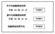
例えば図6に示すように、内視鏡洗浄消毒装置1の設定画面として、内視鏡洗浄消毒装置1の主電源がオフからオンへ変更された時間のうち、1ヶ月分の平均及び1週間分の平均を示す時間である「月平均使用開始時間」及び「週平均使用開始時間」と、該「月平均使用開始時間」または該「週平均使用開始時間」として表示された時間のいずれかの時間に合わせてヒータ15を動作させるための予約設定が可能な「予約実行」スイッチと、が操作パネル8または端末装置201に接続されるモニタ等に表示されるものであっても良い。
For example, as shown in FIG. 6, the setting screen of the endoscope cleaning /
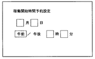
さらに、例えば図6、図7及び図8に示すように、内視鏡洗浄消毒装置1の設定画面として、内視鏡洗浄消毒装置1の使用開始時刻を所望の時刻として予約設定可能な画面が操作パネル8または端末装置201に接続されるモニタ等に表示されるものであっても良い。
Further, for example, as shown in FIGS. 6, 7, and 8, as the setting screen of the endoscope cleaning /
なお、図7は、図6における「予約設定」スイッチが押されることにより遷移した後の画面であり、かつ、予約設定が未設定である場合の画面の一例を示す図である。また、図8は、図7の画面内における日時の入力が完了した場合の画面の一例を示す図である。 FIG. 7 is a diagram showing an example of a screen after transition is made by pressing the “reservation setting” switch in FIG. 6, and when the reservation setting is not set. FIG. 8 is a diagram showing an example of the screen when the date and time input is completed in the screen of FIG.
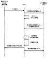
ここで、図6、図7及び図8に示すような設定画面において、内視鏡洗浄消毒装置1の使用開始時刻が予約設定された場合の処理の一例について、図9に示す処理フローに沿って説明を行う。
Here, an example of processing when the use start time of the endoscope cleaning /
まず、操作パネル8または端末装置201において「予約実行」スイッチが押下されることにより、内視鏡洗浄消毒装置1の使用開始時刻の予約が実行されると、CPU11は、図示しない不揮発性メモリに対し、該使用開始時刻の書き込みを行った後、(自身に内蔵された)図示しないタイマーのカウントを開始する。
First, when reservation of the use start time of the endoscope cleaning /
そして、CPU11は、例えば、内視鏡洗浄消毒装置1の主電源が一旦オフされた後、再度オンされた際に、図示しない不揮発性メモリに書き込まれた使用開始時刻の読み出しを行う。
Then, for example, when the main power supply of the endoscope cleaning /
CPU11は、図示しないタイマーのカウントにより、設定された使用開始時刻の30分前に達したことを検出すると、該設定開始時刻に達するタイミングと、消毒液タンク12に貯蔵された消毒液13の温度が予め設定された所定の温度に達するタイミングとが略一致するようにヒータ15を動作させつつ、消毒液13を加温する。
When the
そして、CPU11は、消毒液13の温度が前記所定の温度に達したことを温度センサ14の計測結果により検出すると、消毒液13の加温が完了した旨を示すメッセージ等を操作パネル8または端末装置201のに接続されるモニタ等に表示させるとともに、図示しない不揮発性メモリに書き込まれた使用開始時刻をリセットする。
When the
以上に述べたような、設定画面における使用開始時刻の予約設定が可能な構成が本実施形態の内視鏡洗浄消毒装置1に適用されることにより、図5に示すステップS1に相当する処理(または図4の時刻t2に至る直前までに相当する動作)を、内視鏡101が洗浄槽4にセットされる事前に予め行うことが可能となり、その結果、消毒液13の再加温に要する時間が短縮される。
By applying the configuration capable of setting the use start time on the setting screen as described above to the endoscope cleaning /
なお、本発明は、上述した各実施形態に限定されるものではなく、発明の趣旨を逸脱しない範囲内において種々の変更や応用が可能であることは勿論である。 Note that the present invention is not limited to the above-described embodiments, and various modifications and applications can be made without departing from the spirit of the invention.
1 内視鏡洗浄消毒装置
2 装置本体
4 洗浄槽
6 消毒液供給口
7,14 温度センサ
8 操作パネル
11 CPU
12 消毒液タンク
13 消毒液
15 ヒータ
101 内視鏡
201 端末装置
DESCRIPTION OF
12
Claims (4)
前記内視鏡配置部の内部の温度を計測する第1の温度計測部と、
前記内視鏡配置部において前記内視鏡の消毒を行うための薬液が貯蔵された貯蔵部と、
前記貯蔵部に貯蔵された前記薬液の温度を計測する第2の温度計測部と、
前記貯蔵部に貯蔵された前記薬液を加温する加温部と、
前記第1の温度計測部における第1の計測結果及び前記第2の温度計測部における第2の計測結果を取得し、前記第1の計測結果及び前記第2の計測結果に基づき、前記貯蔵部に貯蔵された前記薬液の温度が、前記内視鏡配置部へ前記薬液が供給される事前に取得した前記第1の計測結果と、前記薬液が最大の消毒効果を呈する温度と、に基づいて算出される所定の到達目標温度に達するまで前記薬液を加温させるための制御を、前記内視鏡配置部へ前記薬液が供給される以前の期間に前記加温部に対して行う制御部と、
を有することを特徴とする内視鏡洗浄消毒装置。 An endoscope placement section having a depth capable of immersing the endoscope;
A first temperature measurement unit for measuring the temperature inside the endoscope arrangement unit;
A storage unit in which a medical solution for disinfecting the endoscope is stored in the endoscope arrangement unit;
A second temperature measurement unit that measures the temperature of the chemical stored in the storage unit;
A heating unit for heating the chemical stored in the storage unit;
A first measurement result in the first temperature measurement unit and a second measurement result in the second temperature measurement unit are acquired, and the storage unit is based on the first measurement result and the second measurement result. The temperature of the medicinal solution stored in the endoscope is based on the first measurement result acquired in advance when the medicinal solution is supplied to the endoscope arrangement unit, and the temperature at which the medicinal solution exhibits the maximum disinfection effect. A control unit that performs control for heating the chemical solution until reaching a predetermined target temperature to be calculated, for the heating unit in a period before the chemical solution is supplied to the endoscope arrangement unit; ,
An endoscope cleaning / disinfecting apparatus comprising:
Priority Applications (1)
| Application Number | Priority Date | Filing Date | Title |
|---|---|---|---|
| JP2007294594A JP5259158B2 (en) | 2007-11-13 | 2007-11-13 | Endoscope cleaning disinfection device |
Applications Claiming Priority (1)
| Application Number | Priority Date | Filing Date | Title |
|---|---|---|---|
| JP2007294594A JP5259158B2 (en) | 2007-11-13 | 2007-11-13 | Endoscope cleaning disinfection device |
Publications (2)
| Publication Number | Publication Date |
|---|---|
| JP2009118962A JP2009118962A (en) | 2009-06-04 |
| JP5259158B2 true JP5259158B2 (en) | 2013-08-07 |
Family
ID=40811803
Family Applications (1)
| Application Number | Title | Priority Date | Filing Date |
|---|---|---|---|
| JP2007294594A Expired - Fee Related JP5259158B2 (en) | 2007-11-13 | 2007-11-13 | Endoscope cleaning disinfection device |
Country Status (1)
| Country | Link |
|---|---|
| JP (1) | JP5259158B2 (en) |
Families Citing this family (3)
| Publication number | Priority date | Publication date | Assignee | Title |
|---|---|---|---|---|
| CN104107448A (en) * | 2013-04-19 | 2014-10-22 | 美的集团股份有限公司 | Method and device for controlling disinfector |
| EP3111826A4 (en) * | 2015-02-09 | 2017-12-06 | Olympus Corporation | Endoscope reprocessor |
| CN113679326B (en) * | 2021-08-17 | 2024-03-22 | 岱川医疗(深圳)有限责任公司 | Endoscope workstation |
Family Cites Families (1)
| Publication number | Priority date | Publication date | Assignee | Title |
|---|---|---|---|---|
| JPH10290776A (en) * | 1997-04-21 | 1998-11-04 | Olympus Optical Co Ltd | Washing and disinfecting device for endoscope |
-
2007
- 2007-11-13 JP JP2007294594A patent/JP5259158B2/en not_active Expired - Fee Related
Also Published As
| Publication number | Publication date |
|---|---|
| JP2009118962A (en) | 2009-06-04 |
Similar Documents
| Publication | Publication Date | Title |
|---|---|---|
| JP5966114B1 (en) | Leak tester and endoscope reprocessor | |
| JP5259158B2 (en) | Endoscope cleaning disinfection device | |
| JP2000175993A (en) | Cleaner for medical appliances | |
| JP5121413B2 (en) | Endoscope cleaning disinfection device | |
| WO2013031388A1 (en) | Endoscope processing device | |
| JP5198961B2 (en) | Endoscope washing machine management system | |
| JP2009254682A (en) | Endoscope washer management system | |
| JP5966097B1 (en) | Endoscope reprocessor | |
| JPH0815481B2 (en) | Endoscope device | |
| CN211751314U (en) | Disposable automatic heating type multifunctional laparoscopic aspirator | |
| JP3672614B2 (en) | Bath water circulation device having an electrolysis sterilizer | |
| JPH0723904A (en) | Endoscope washing and disinfecting device | |
| JP5195252B2 (en) | Electric water heater | |
| JP5259165B2 (en) | Endoscope cleaning disinfection device | |
| JP2016185228A (en) | Pneumoperitoneum device, and operation method of pneumoperitoneum device | |
| JP5748705B2 (en) | Steam sterilizer | |
| CN116481172A (en) | Automatic heating control device and method for disinfectant | |
| JPH0731588A (en) | Endoscope washing and disinfecting device | |
| JP7277750B2 (en) | bath equipment | |
| JP2002078678A (en) | Endoscope cleaning and disinfecting system | |
| JP2007267973A (en) | Endoscope cleaning and disinfection equipment | |
| JP3100000U (en) | Local cleaning equipment | |
| US20240260823A1 (en) | Systems and methods for the identification, evaluation, and/or closed-loop reprocessing of lumens | |
| JP2887165B2 (en) | Endoscope | |
| KR20190081845A (en) | Heating Device For Providing Function For Sanitizing Nursing Bottle |
Legal Events
| Date | Code | Title | Description |
|---|---|---|---|
| A621 | Written request for application examination |
Free format text: JAPANESE INTERMEDIATE CODE: A621 Effective date: 20101001 |
|
| A977 | Report on retrieval |
Free format text: JAPANESE INTERMEDIATE CODE: A971007 Effective date: 20120817 |
|
| A131 | Notification of reasons for refusal |
Free format text: JAPANESE INTERMEDIATE CODE: A131 Effective date: 20120821 |
|
| A521 | Request for written amendment filed |
Free format text: JAPANESE INTERMEDIATE CODE: A523 Effective date: 20121002 |
|
| TRDD | Decision of grant or rejection written | ||
| A01 | Written decision to grant a patent or to grant a registration (utility model) |
Free format text: JAPANESE INTERMEDIATE CODE: A01 Effective date: 20130402 |
|
| A61 | First payment of annual fees (during grant procedure) |
Free format text: JAPANESE INTERMEDIATE CODE: A61 Effective date: 20130424 |
|
| FPAY | Renewal fee payment (event date is renewal date of database) |
Free format text: PAYMENT UNTIL: 20160502 Year of fee payment: 3 |
|
| R151 | Written notification of patent or utility model registration |
Ref document number: 5259158 Country of ref document: JP Free format text: JAPANESE INTERMEDIATE CODE: R151 |
|
| S111 | Request for change of ownership or part of ownership |
Free format text: JAPANESE INTERMEDIATE CODE: R313111 |
|
| R350 | Written notification of registration of transfer |
Free format text: JAPANESE INTERMEDIATE CODE: R350 |
|
| S531 | Written request for registration of change of domicile |
Free format text: JAPANESE INTERMEDIATE CODE: R313531 |
|
| R350 | Written notification of registration of transfer |
Free format text: JAPANESE INTERMEDIATE CODE: R350 |
|
| R250 | Receipt of annual fees |
Free format text: JAPANESE INTERMEDIATE CODE: R250 |
|
| R250 | Receipt of annual fees |
Free format text: JAPANESE INTERMEDIATE CODE: R250 |
|
| R250 | Receipt of annual fees |
Free format text: JAPANESE INTERMEDIATE CODE: R250 |
|
| R250 | Receipt of annual fees |
Free format text: JAPANESE INTERMEDIATE CODE: R250 |
|
| R250 | Receipt of annual fees |
Free format text: JAPANESE INTERMEDIATE CODE: R250 |
|
| LAPS | Cancellation because of no payment of annual fees |