JP5254915B2 - Suspended particulate matter generator - Google Patents
Suspended particulate matter generator Download PDFInfo
- Publication number
- JP5254915B2 JP5254915B2 JP2009210902A JP2009210902A JP5254915B2 JP 5254915 B2 JP5254915 B2 JP 5254915B2 JP 2009210902 A JP2009210902 A JP 2009210902A JP 2009210902 A JP2009210902 A JP 2009210902A JP 5254915 B2 JP5254915 B2 JP 5254915B2
- Authority
- JP
- Japan
- Prior art keywords
- particulate matter
- suspended particulate
- electrode
- air flow
- suspended
- Prior art date
- Legal status (The legal status is an assumption and is not a legal conclusion. Google has not performed a legal analysis and makes no representation as to the accuracy of the status listed.)
- Expired - Fee Related
Links
Images


Description
本発明は、大気中に浮遊する粒子状物質の濃度測定装置の動作確認に主として用いられる浮遊粒子状物質発生装置に関し、特に2.5μm以下の微小粒子を含む浮遊粒子状物質含有空気を安定して得ることができる浮遊粒子状物質発生装置に関したものである。 The present invention relates to a suspended particulate matter generator mainly used for confirming the operation of a concentration measuring device for particulate matter suspended in the air, and in particular, stabilizes suspended particulate matter-containing air containing microparticles of 2.5 μm or less. The present invention relates to a suspended particulate matter generator that can be obtained in this way.
大気中には、種々の粒径の浮遊粒子状物質が存在する。粒径が10μm以下の浮遊粒子状物質は、人が呼吸するに際し、気道で濾過されずに、吸引され、肺に沈降することから、特に人に対する毒性が高い。このような理由で、公害対策基本法に基づく大気汚染に関する環境基準では、大気中の浮遊粒子状物質は、粒径が10μm以下のものと規定されている。そして、従来からこの規定に従って、粒径10μm以下の浮遊粒子状物質の重量を測定する装置が市販されている。なお、本明細書では、浮遊粒子状物質と記載するものは粒径10μm以下の粒子状物質とは限らずに、大気中に浮遊する粒子状物質とする。 There are suspended particulate matter having various particle sizes in the atmosphere. The suspended particulate matter having a particle size of 10 μm or less is particularly toxic to humans because it is sucked and settled in the lung without being filtered by the respiratory tract when a person breathes. For this reason, the environmental standards related to air pollution based on the Pollution Control Basic Law stipulate that the suspended particulate matter in the atmosphere has a particle size of 10 μm or less. Conventionally, an apparatus for measuring the weight of suspended particulate matter having a particle size of 10 μm or less is commercially available according to this rule. In this specification, what is described as a suspended particulate matter is not limited to a particulate matter having a particle size of 10 μm or less, but is assumed to be a particulate matter suspended in the atmosphere.
大気中の浮遊粒子状物質には、粒径2.5μm程度を境として粗大粒子状物質(coarse particle,以下CPと略すことがある)と微小粒子状物質(fine particle,以下FPと略すことがある)とが存在する。 Airborne particulate matter may be abbreviated as coarse particles (hereinafter abbreviated as CP) and fine particles (hereinafter referred to as FP) with a particle size of about 2.5 μm as a boundary. Exist).
CPは、海塩粒子や土壌に由来する砂塵など自然に生じるものを含んでいる。これに対し、FPは工場等から排出されるばいじんやディーゼル車等の発生源から直接大気に放出される一次生成粒子と、硫黄酸化物(SOx)、窒素酸化物(NOx)、揮発性有機化合物(VOC)等のガス状物質が大気中で粒子状物質に変化する二次生成粒子がある。最近、都市部における大気中の浮遊粒子状物質の粒径についての人体に及ぼす疫学調査の結果、FPは低濃度においても、心血管疾患、肺がん、喘息などの疾患に影響すると考えられ、FPの重量濃度の増加が死亡率を増加させていると考えられている。 CP contains naturally occurring things such as sea salt particles and dust derived from soil. FP, on the other hand, produces primary particles directly released into the atmosphere from sources such as dust and diesel vehicles emitted from factories, sulfur oxides (SOx), nitrogen oxides (NOx), and volatile organic compounds. There are secondary generated particles in which a gaseous substance such as (VOC) changes into a particulate substance in the atmosphere. Recently, as a result of epidemiological studies on the human body about the particle size of airborne particulate matter in urban areas, FP is thought to affect diseases such as cardiovascular disease, lung cancer and asthma even at low concentrations. Increased weight concentrations are believed to increase mortality.
そこで、従来、粒径の小さいFPを捕集し、捕集したFPの重量濃度(1m2の大気中に含まれるFPの重量)を測定する測定装置が開発されている。測定装置の一例として、例えば、一定量の大気中に含まれるFPを連続的に測定する装置がある。この測定装置は、FPを含む試料大気を吸引し、吸引した試料大気に含まれるFPをテープフィルタ上に捕集し、捕集したFPをβ線吸収法で重量測定する。当該測定装置で大気中のFPの質量を測定することにより、大気の汚染状態を把握し、対策を練ることができる。なお、β吸収法の他に、TEOM(Tapered Element Oscillating Microbalance)、光散乱法も知られている。 Therefore, conventionally, a measuring apparatus has been developed that collects FP having a small particle diameter and measures the weight concentration of the collected FP (weight of FP contained in 1 m 2 atmosphere). As an example of the measuring device, for example, there is a device that continuously measures FP contained in a certain amount of air. This measuring apparatus sucks the sample atmosphere containing FP, collects the FP contained in the sucked sample atmosphere on a tape filter, and measures the weight of the collected FP by the β-ray absorption method. By measuring the mass of FP in the atmosphere with the measurement device, it is possible to grasp the pollution state of the atmosphere and devise countermeasures. In addition to the β absorption method, TEOM (Tapered Element Oscillating Microbalance) and a light scattering method are also known.
上記測定装置は、非常に精密な機械であるため、定期的な検査、メンテナンスが欠かせない。従来は、上記測定装置の動作を検査および校正するために、例えば、所定量のFPと重量が等しい等価膜がテープフィルタ上に設置された状態で、β線吸収法で重量測定が行われる。これにより、β線吸収法を用いた重量測定部の動作を検査し、必要に応じて重量測定部の校正を行うことができる。等価膜をフィルタ上に設置して行う校正は、静的校正と呼ばれる。 Since the measuring device is a very precise machine, regular inspection and maintenance are indispensable. Conventionally, in order to inspect and calibrate the operation of the measurement apparatus, for example, weight measurement is performed by a β-ray absorption method in a state where an equivalent film having a weight equal to a predetermined amount of FP is installed on a tape filter. Thereby, the operation of the weight measuring unit using the β-ray absorption method can be inspected, and the weight measuring unit can be calibrated as necessary. Calibration performed by installing an equivalent membrane on a filter is called static calibration.
しかしながら、上記の静的校正は、測定装置全体を作動させた状態で行われるものではないため、重量測定部以外の部分、例えば、吸引ポンプ、テープフィルタ移動機構等の動作を検査、校正することはできない。従って、測定装置全体を作動させた状態で装置全体の動作を検査、校正(いわゆる動的校正)するために、FPを安定して測定装置に供給する装置の登場が望まれている。 However, since the above static calibration is not performed in a state where the entire measuring apparatus is operated, the operation other than the weight measuring unit, for example, the operation of the suction pump, the tape filter moving mechanism, etc. is inspected and calibrated. I can't. Therefore, in order to inspect and calibrate (so-called dynamic calibration) the operation of the entire apparatus in a state where the entire measuring apparatus is in operation, it is desired to introduce an apparatus that stably supplies FP to the measuring apparatus.
なお、非特許文献1には、超音波噴霧器に関する記載がある。この超音波噴霧器は、シリンジポンプからチャンバー内に供給された液体を、圧電結晶振動子で振動させてオリフィスから空気流とともにエアロゾルとして放出するものである。しかしながら、この超音波噴霧器では、1〜10μmの液体粒子を放出することができるが、同じ粒径の液体粒子を長時間に渡って安定して放出することが難しい。また、この超音波噴霧器では、1μm未満の微小粒子を放出することは難しい。さらに、装置全体として大きくなり、持ち運びが不便で、微小粒子状物質の連続重量測定装置に簡単に現場で接続して動的校正装置として使用することが難しい。
Note that Non-Patent
本発明は、このような実情に鑑みてなされたもので、空気力学的粒径が特に2.5μm以下の浮遊粒子状物質を含む浮遊粒子状物質含有空気を安定して得ることができる浮遊粒子状物質発生装置の提供を目的とする。 The present invention has been made in view of such circumstances, and suspended particles that can stably obtain suspended particulate matter-containing air containing suspended particulate matter having an aerodynamic particle size of 2.5 μm or less. The purpose is to provide a particulate matter generator.
第1の発明は、多数の浮遊粒子状物質を発生させる装置であって、
上記浮遊粒子状物質の基となる粒子状物質を溶質とする溶液を供給する溶液供給部と、
第1電位が付与され、上記溶液供給部から供給された溶液を液滴として先端の孔から放出する毛細管状の第1電極と、
上記第1電位に対して所定の電位差を有する第2電位が付与され、上記孔に対し所定の間隔をおいて対向配置され、上記粒子状物質を含む液滴が通過可能な構造を有する第2電極と、
上記第1電極と上記第2電極に上記所定の電位差を発生させる電圧印加部と、
上記第1電極から上記第2電極に向かう空気流を発生させる空気流発生部とを備え、
上記第1電極から放出された液滴は上記電位差によって上記第2電極に引っ張られて飛行し、飛行中の上記液滴は上記空気流に触れることで乾燥しつつ微細分離を繰り返し、当該微細分離の繰り返しにより、分散した多数の液滴が生じ、当該多数の液滴は上記空気流に乗って上記第2電極を通過し、通過後も上記微細分離を繰り返し、当該微細分離の繰り返しにより、分散した多数の浮遊粒子状物質が生じることを特徴とする。
The first invention is an apparatus for generating a large number of suspended particulate matter,
A solution supply unit for supplying a solution having a particulate matter as a base of the suspended particulate matter as a solute;
A capillary-shaped first electrode to which a first potential is applied and which discharges the solution supplied from the solution supply unit as a droplet from a hole at the tip;
A second potential having a predetermined potential difference with respect to the first potential, a second potential having a structure in which the droplets containing the particulate matter are allowed to pass through the pores with a predetermined distance therebetween. Electrodes,
A voltage applying unit that generates the predetermined potential difference between the first electrode and the second electrode;
An air flow generator for generating an air flow from the first electrode toward the second electrode,
The droplet discharged from the first electrode is pulled by the second electrode due to the potential difference and flies, and the droplet in flight repeats fine separation while being dried by touching the air flow, and the fine separation Is repeated, and a large number of dispersed liquid droplets are generated. The large number of liquid droplets ride on the air flow and pass through the second electrode, and after the passage, the fine separation is repeated. A large number of suspended particulate matter is produced.
第1の発明によれば、第1電極内の溶液は第1電極に対応する電荷が付与されて帯電する。第1電極から放出された液滴は電位差によって第2電極に引っ張られて飛行し、飛行中の液滴は空気流に触れることで乾燥しつつ微細分離する。微細分離の原理は、乾燥によって粒子径が小さくなることで液滴表面の電荷密度が高くなり、電荷同士の反発力によって液滴が分裂することによる。当該微細分離が繰り返されるにより、分散した多数の液滴が生じ、当該多数の液滴は空気流に乗って上記第2電極を通過する。第2電極を通過した多数の液滴は、通過後も上記微細分離を繰り返し、当該微細分離の繰り返しにより、分散した多数の浮遊粒子状物質が生じる。これは、エレクトロスプレーイオン化法(ESI)の原理を利用したものである。これにより、空気力学的粒径が特に2.5μm以下の略同一径の固体粒子を含む浮遊粒子状物質含有空気を長時間に渡って安定して得ることができる。1μm以下の略同一径の微小粒子状物質を含む微小粒子状物質含有空気を長時間に渡って安定して得ることも可能である。なお、本発明において得られる浮遊粒子状物質は2.5μm以下の粒子状物質に限定されず、2.5μmを超える粒子状物質であってもよい。 According to the first invention, the solution in the first electrode is charged with the charge corresponding to the first electrode. The droplets discharged from the first electrode fly by being pulled by the second electrode due to the potential difference, and the droplets in flight are finely separated while being dried by touching the air flow. The principle of fine separation is due to the fact that the charge density on the droplet surface increases as the particle diameter decreases due to drying, and the droplet breaks up due to the repulsive force between the charges. By repeating the fine separation, a large number of dispersed droplets are generated, and the large number of droplets ride on the air flow and pass through the second electrode. A large number of droplets that have passed through the second electrode repeat the above-mentioned fine separation even after the passage, and a large number of dispersed particulate matters are generated by the repetition of the fine separation. This utilizes the principle of electrospray ionization (ESI). Thereby, suspended particulate matter-containing air containing solid particles having an aerodynamic particle size of approximately the same diameter of 2.5 μm or less can be obtained stably over a long period of time. It is also possible to stably obtain air containing fine particulate matter containing fine particulate matter having substantially the same diameter of 1 μm or less over a long period of time. The suspended particulate matter obtained in the present invention is not limited to a particulate matter of 2.5 μm or less, and may be a particulate matter exceeding 2.5 μm.
第2の発明は、第1の発明において、
上記浮遊粒子状物質の飛行中に当該浮遊粒子状物質の光学特性を検知し、当該光学特性に基づき、上記浮遊粒子状物質の粒子濃度を測定する粒子濃度測定部をさらに備えたことを特徴とする。
According to a second invention, in the first invention,
The apparatus further comprises a particle concentration measuring unit that detects optical characteristics of the suspended particulate matter during the flight of the suspended particulate matter and measures the particle concentration of the suspended particulate matter based on the optical characteristics. To do.
第2の発明によれば、浮遊粒子状物質の光学特性に基づき、第2電極を通過した浮遊粒子状物質の粒子濃度が測定される。ここで言う「光学特性」は特に限定されないが、例えば、光散乱特性、光吸収特性である。また、ここで言う「粒子濃度」は、単位体積(1m3)の空気に含まれる発生した浮遊粒子状物質の個数あるいは重量である。発生した浮遊粒子状物質の粒径および密度は定常的であるため、数濃度と重量濃度の算出が可能である。粒子濃度測定部は、例えば、発生した浮遊粒子状物質の個数を当該浮遊粒子状物質の光散乱特性に基づいて算出し、算出された個数に基づく重量換算によって得た重量を空気の体積で除算することにより、重量濃度を算出することができる。 According to the second invention, the particle concentration of the suspended particulate matter that has passed through the second electrode is measured based on the optical characteristics of the suspended particulate matter. The “optical characteristics” referred to here are not particularly limited, and are, for example, light scattering characteristics and light absorption characteristics. The “particle concentration” referred to here is the number or weight of generated suspended particulate matter contained in air of unit volume (1 m 3 ). Since the particle size and density of the generated suspended particulate matter are constant, the number concentration and the weight concentration can be calculated. The particle concentration measurement unit, for example, calculates the number of generated suspended particulate matter based on the light scattering characteristics of the suspended particulate matter, and divides the weight obtained by weight conversion based on the calculated number by the volume of air. By doing so, the weight concentration can be calculated.
第3の発明は、第2の発明において、
上記粒子濃度測定部で測定された浮遊粒子状物質の粒子濃度に基づき、上記溶液供給部の溶液供給量または上記空気流発生部の空気流量の少なくともいずれか一方をフィードバック制御することを特徴とする。
According to a third invention, in the second invention,
Feedback control of at least one of the solution supply amount of the solution supply unit and the air flow rate of the air flow generation unit based on the particle concentration of the suspended particulate matter measured by the particle concentration measurement unit; .
第3の発明によれば、発生した浮遊粒子状物質の粒子濃度が、予め定められた粒子濃度より大きすぎれば溶液供給量または空気流量の少なくともいずれか一方を減らし、発生した浮遊粒子状物質の粒子濃度が、予め定められた粒子濃度より小さすぎければ溶液供給量または空気流量の少なくともいずれか一方を増やすフィードバック制御をすることができる。このフィードバック制御により、浮遊粒子状物質の粒子濃度を、予め定められた粒子濃度に調節することができる。 According to the third invention, if the particle concentration of the generated suspended particulate matter is too larger than the predetermined particle concentration, at least one of the solution supply amount and the air flow rate is reduced, and the generated suspended particulate matter If the particle concentration is too smaller than a predetermined particle concentration, feedback control can be performed to increase at least one of the solution supply amount and the air flow rate. By this feedback control, the particle concentration of the suspended particulate matter can be adjusted to a predetermined particle concentration.
第4の発明は、第1の発明において、
大気中の浮遊粒子状物質を捕集して、捕集した上記浮遊粒子状物質の重量濃度を測定する測定装置の動作を確認するための装置であり、当該測定装置に接続可能に構成されていることを特徴とする。
According to a fourth invention, in the first invention,
A device for collecting the suspended particulate matter in the atmosphere and measuring the weight concentration of the collected suspended particulate matter and confirming the operation of the measuring device, and configured to be connectable to the measuring device. It is characterized by being.
第4の発明によれば、FPの質量測定装置全体を作動させた状態で当該測定装置全体の動作を検査、校正(いわゆる動的校正)するために、FPを安定して当該測定装置に供給することができる。 According to the fourth invention, in order to inspect and calibrate (so-called dynamic calibration) the operation of the entire measuring device while the entire mass measuring device of the FP is operated, the FP is stably supplied to the measuring device. can do.
第5の発明は、第1の発明において、
上記浮遊粒子状物質は、硫酸マグネシウムであることを特徴とする。
According to a fifth invention, in the first invention,
The suspended particulate material is magnesium sulfate.
第5の発明によれば、他の物質を用いる場合よりも、比較的多くの浮遊粒子状物質を長時間安定して発生させることができる。 According to the fifth aspect of the invention, it is possible to stably generate a relatively large amount of suspended particulate matter for a long time, compared to the case of using other materials.
本発明によれば、空気力学的粒径が特に2.5μm以下の固体粒子状物質を含む浮遊粒子状物質含有空気を安定して得ることができる。 According to the present invention, suspended particulate matter-containing air containing a solid particulate matter having an aerodynamic particle size of 2.5 μm or less can be obtained stably.
(第1実施形態)
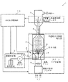
以下、本発明の第1実施形態に係る浮遊粒子状物質発生装置について、図面を参照しつつ説明する。図1は、第1実施形態に係る浮遊粒子状物質発生装置の構成を示す図である。図2は、図1における第2電極のバリエーションを示す図である。
(First embodiment)
Hereinafter, a suspended particulate matter generator according to a first embodiment of the present invention will be described with reference to the drawings. FIG. 1 is a diagram showing a configuration of a suspended particulate matter generator according to the first embodiment. FIG. 2 is a diagram showing a variation of the second electrode in FIG.
第1実施形態に係る浮遊粒子状物質発生装置1(以下、発生装置1と略称する)は、多数の微小粒子状物質を発生させる装置である。本明細書における「浮遊粒子状物質」には、粒径2.5μm程度を境として粗大粒子状物質(coarse particle,以下CPと略すことがある)と微小粒子状物質(fine particle,以下FPと略すことがある)とが存在する。「微小粒子状物質」は、2.5μm以下、特に1μm以下の微小粒子を意味する。 The suspended particulate matter generator 1 (hereinafter abbreviated as the generator 1) according to the first embodiment is a device that generates a large number of fine particulate matter. In the present specification, “floating particulate matter” includes coarse particulate matter (hereinafter abbreviated as CP) and fine particulate matter (hereinafter referred to as FP) with a particle diameter of about 2.5 μm as a boundary. May be abbreviated). “Microparticulate material” means microparticles of 2.5 μm or less, in particular 1 μm or less.
発生装置1は、溶液供給部2と、第1電極3と、第2電極4と、電圧印加部5と、空気流発生部6とを備えている。
The
溶液供給部2は、粒子状物質(例えば、微小粒子状物質)を溶質とする溶液を第1電極3に供給する。溶液供給部2は、送液ポンプ12を有しており、送液ポンプ12の回転数を調節することにより、溶液の供給量(L/min)を調節することができる。溶質とする粒子状物質の種類は特に限定されるものではないが、好ましくは、例えば、硫酸マグネシウム(MgSO4)とすることができる。なお、粒子状物質は他の物質でもよく、例えば、硝酸カルシウム(Ca(NO3)2)、塩化ナトリウム(NaCl)であってもよい。溶媒についても特に限定されるものではないが、例えば、水とエタノールを1:1の割合で混合したものとすることができる。エタノールを混合することによって溶媒が乾燥し、固体粒子にし易くする。
The
第1電極3は、第1電位V1が付与され、溶液供給部2から供給された溶液を液滴として先端の孔13から放出するニードル管状の電極である。第1電極3は、例えば金属製である。
The
第2電極4は、第1電位V1に対して所定の電位差VSを有する第2電位V2が付与される。第2電極4は、孔13に対し所定の間隔をおいて対向配置され、空気流に乗った微小粒子状物質が通過可能な間隙18または孔部14を有する。第2電極4は、例えば金属製である。
The
第2電極4の形態は、特に限定されるものではないが、例えば、図2(A)〜(E)に示されるいずれか形態とすることができる。図2(A)に示される第2電極4は、互いに平行で且つ間隙18をあけて設けられた2本の棒状部19で構成されている。間隙18の幅は、例えば、5〜15mm程度とされるが、特に限定はされない。
Although the form of the
図2(B)に示される第2電極4は、中心部に孔部14が形成された金属製の円板状部50である。なお、図2(B)に示される孔部14は円形状であるが、これに代えて三角形状、四角形状、5角以上の多角形状のいずれであってもよい。孔部14の径は、例えば15mmとされるが、この値に限定されない。
The
図2(C)に示される第2電極4は、リング状部40と、リング状部40の開口部41に位置するように当該リング状部40に装着されたメッシュ状部42とを含む。メッシュ状部42は、例えば、図2(C)に示されるように、4本の金属線材43をメッシュ状に組み合わせた構造とすることができる。孔部14は、4本の金属線材43で囲まれる正方形状の領域である。リング状部40の内径は例えば60mmとされ、外径は例えば76mmとされるが、これらの値に限定されない。また、メッシュ状部42を構成する平行な線材43の間隔は例えば15mmとされるが、この値に限定されない。
The
図2(D)に示される第2電極4は、リング状部40と、リング状部40の開口部41に位置するように当該リング状部40に装着された放射状部44とを含む。放射状部44は、例えば、図2(D)に示されるように、六角形状の金属線材45の各頂点に直線状の金属線材46が組み合わされた構造とすることができる。なお、六角形状の金属線材45に代えて、三角形状、四角形状、五角形状、或いは七角以上の角を有する多角形状の線材を設けてもよい。いずれの多角形状を採用する場合でも、各頂点に直線状の線材が組み合わされる。孔部14は、図2(D)に示される例では、六角形状の金属線材45で囲まれる領域である。
The
図2(E)に示される第2電極4は、リング状部40と、リング状部40の開口部41に位置するように当該リング状部40に装着された放射状部47とを含む。放射状部47は、例えば、図2(E)に示されるように、円形状の金属線材48の周囲に4本の直線状の線材49が組み合わされた構造とすることができる。なお、直線状の線材49の本数は4本に限定されず、例えば、2本、3本、或いは5本以上であってもよい。なお、図2(E)に示される直線状の線材49の太さは、図2(D)に示される直線状の線材46よりも太くなっているが、図2(D)と同じく細い線材であってもよい。孔部14は、図2(E)に示される例では、六角形状の金属線材45で囲まれる領域である。円形状の金属線材48の内径は、例えば15mmとされるが、この値に限定されない。
The
電圧印加部5は、第1電極3と第2電極4に所定の電位差VSを発生させる。第1電極3には、例えば、第2電極4に対して例えば5〜7ボルトの間の任意の電位が付与される。逆に、第2電極4に、第1電極3に対して例えば5〜7ボルトの間の任意の電位が付与されてもよい。
The
第1電極3と第2電極4は、第1流通管7内に収められている。第1流通管7は、第2流通管8に接続され、第2流通管8は第3流通管9に接続されている。第2流通管8は、第1流通管7および第3流通管9よりも細くなっている。第3流通管9は、FPの質量測定装置(図示せず)に接続される。第3流通管9には、流量センサ10が設けられている。流量センサ10は、第3流通管9内を流れる空気の量(L/min)を測定する。流量センサ10は、CPU11に接続されている。CPU11は、流量センサ10から入力した流量データに基づき、電圧印加部5の印加電圧、溶液供給部2の溶液供給量(L/min)、および空気流発生部6の空気流量を制御する。第1電極3の先端と第2電極4の間隔は、例えば1cm程度とされる。
The
空気流発生部6は、第1電極3から第2電極4に向かう空気流を発生させる。空気流は乾燥手段によりできるだけ乾燥させた空気流であることが好ましい。空気流発生部6は、例えば、送風ファンで構成することができる。なお、空気流は、装置外部の空気を微粒子除去フィルタで除去したクリーンな空気であることが好ましい。第3流通管9内を流れる空気の量が、例えば20L/minとなるように、送風ファンの回転数が制御される。
The air
次に、発生装置1の動作について説明する。
まず、溶液供給部2から溶液が第1電極3に供給される。次いで、第1電極3から放出された液滴は電位差によって第2電極4に引っ張られて飛行する。飛行中の液滴は空気流に触れることで乾燥しつつ微細分離を繰り返し、当該微細分離の繰り返しにより、常圧下で分散した多数の液滴になる。当該多数の液滴は空気流に乗って間隙18または孔部14を通過する。当該多数の液滴は、間隙18または孔部14を通過後も微細分離を繰り返し、当該微細分離の繰り返しにより、分散した多数の浮遊粒子状物質が生じる。微細分離の原理は、乾燥によって粒子径が小さくなることで液滴表面の電荷密度が高くなり、電荷同士の反発力によって液滴が分裂することによる。当該微細分離が繰り返されるにより、常圧下で分散した多数の微小粒子状物質が生じる。これにより、発生装置1によれば、2.5μm以下、特に1μm以下の略同一径の浮遊粒子状物質を含む浮遊粒子状物質含有空気を長時間に渡って安定して得ることができる。以上が、発生装置1の主な動作である。
Next, operation | movement of the
First, a solution is supplied from the
図3は電圧印加部5の印加電圧と発生した微小粒子状物質の濃度との関係を示す図である。図3に示されるように、印加電圧(電位差)が6.0〜6.5kVである時に、微小粒子状物質の濃度が最大になる。よって、印加電圧(電位差)は6.0〜6.5kVが好ましいことが分かる。
なお、濃度測定は、空気流量を20L/minとし、水とエタノールを1:1で混合してなる溶媒に0.1%濃度で硫酸マグネシウムを溶かした溶液を用い、溶液流量を10μL/min、とした条件の下で行った。
FIG. 3 is a diagram showing the relationship between the applied voltage of the
In addition, the concentration measurement uses an air flow rate of 20 L / min, a solution obtained by dissolving magnesium sulfate at a concentration of 0.1% in a solvent obtained by mixing water and ethanol at 1: 1, and the solution flow rate is 10 μL / min. It was performed under the conditions.
図4は、溶質の種類と発生した微小粒子状物質の濃度との関係を示す図である。図4に示されるように、溶質が硫酸マグネシウムである時に、微小粒子状物質の濃度が最大になる。よって、溶質は硫酸マグネシウムが好ましいことが分かる。
なお、濃度測定は、空気流量を20L/minとし、水とエタノールを1:1で混合してなる溶媒に0.1%濃度で硫酸マグネシウムを溶かした溶液を用い、溶液流量を10μL/min、線型0.475とした条件の下で行った。
FIG. 4 is a diagram showing the relationship between the kind of solute and the concentration of the generated fine particulate matter. As shown in FIG. 4, when the solute is magnesium sulfate, the concentration of microparticulate matter is maximized. Therefore, it turns out that magnesium sulfate is preferable as a solute.
In addition, the concentration measurement uses an air flow rate of 20 L / min, a solution obtained by dissolving magnesium sulfate at a concentration of 0.1% in a solvent obtained by mixing water and ethanol at 1: 1, and the solution flow rate is 10 μL / min. The test was performed under the condition of a linear type of 0.475.
発生装置1は、大気中の浮遊粒子状物質(例えば微小粒子状物質)を捕集し捕集した浮遊粒子状物質の重量濃度を測定する測定装置の動作を確認、校正するために、測定装置に浮遊粒子状物質を供給する装置であり、当該測定装置に接続可能に構成されている。ここに言う「浮遊粒子状物質の重量濃度」とは、単位体積(1m3)の大気中に含まれる浮遊粒子状物質の重量である。
The
よって、発生装置1によれば、浮遊粒子状物質の重量濃度測定装置全体を作動させた状態で当該測定装置全体の動作を検査、校正(いわゆる動的校正)するために、浮遊粒子状物質(例えば、粒径が2.5μm以下の微小粒子状物質)を安定して当該測定装置に供給することができる。
Therefore, according to the
(第2実施形態)
本発明の第2実施形態について、図面を参照しつつ説明する。
図5は、第2実施形態に係る浮遊粒子状物質発生装置の構成を示す図である。なお、第1実施形態と同様の構成については、図1と同一の参照符号を付して、その説明を省略する。
(Second Embodiment)
A second embodiment of the present invention will be described with reference to the drawings.
FIG. 5 is a diagram illustrating a configuration of the suspended particulate matter generation device according to the second embodiment. In addition, about the structure similar to 1st Embodiment, the same referential mark as FIG. 1 is attached | subjected and the description is abbreviate | omitted.
第2実施形態に係る浮遊粒子状物質発生装置15(以下、発生装置15と称する)が第1実施形態と異なる点は、粒子濃度測定部16をさらに備えたことであり、その他の構成は第1実施形態と同様である。 The difference between the suspended particulate matter generating device 15 (hereinafter referred to as the generating device 15) according to the second embodiment and the first embodiment is that the particle concentration measuring unit 16 is further provided. This is the same as in the first embodiment.
粒子濃度算出部16は、間隙18または孔部14を通過した浮遊粒子状物質の光学特性を検知し、当該光学特性に基づき、間隙18または孔部14を通過した浮遊粒子状物質の数濃度及び重量濃度を算出する。ここで言う「光学特性」は特に限定されないが、例えば、光散乱特性、光吸収特性である。また、ここで言う「粒子濃度」は、単位体積(1m3)の空気に含まれる発生した浮遊粒子状物質の個数(数濃度)あるいは重量(重量濃度)である。発生した浮遊粒子状物質の粒径および密度は定常的であるため、数濃度と重量濃度の算出が可能である。粒子濃度測定部16は、第2流通管8に設けられた光学検出部17から出力された光学データに基づき、浮遊粒子状物質の数濃度及び重量濃度を算出する。粒子濃度測定部16は、例えば、発生した浮遊粒子状物質の個数を当該浮遊粒子状物質の光散乱特性または光吸収特性に基づいて算出し、算出された個数に基づく重量換算によって得た重量を空気の体積流量で除算することにより、重量濃度を算出することができる。
The particle concentration calculation unit 16 detects the optical characteristics of the suspended particulate matter that has passed through the gap 18 or the hole portion 14, and based on the optical characteristics, the number concentration of the suspended particulate matter that has passed through the gap 18 or the pore portion 14 and Calculate the weight concentration. The “optical characteristics” referred to here are not particularly limited, and are, for example, light scattering characteristics and light absorption characteristics. Further, the “particle concentration” referred to here is the number (number concentration) or weight (weight concentration) of the generated suspended particulate matter contained in air of unit volume (1 m 3 ). Since the particle size and density of the generated suspended particulate matter are constant, the number concentration and the weight concentration can be calculated. The particle concentration measurement unit 16 calculates the number concentration and the weight concentration of the suspended particulate matter based on the optical data output from the
CPU11は、個数算出部16で算出された個数に基づき、溶液供給部2の溶液供給量または空気流発生部6の空気流量の少なくともいずれか一方をフィードバック制御する。
The CPU 11 feedback-controls at least one of the solution supply amount of the
発生装置15によれば、浮遊粒子状物質の光学特性に基づき、間隙18または孔部14を通過した浮遊粒子状物質の粒子濃度が算出される。
According to the
また、発生装置15によれば、発生した浮遊粒子状物質の粒子濃度が、予め定められた粒子濃度より大きすぎれば溶液供給量または空気流量の少なくともいずれか一方を減らし、発生した浮遊粒子状物質の粒子濃度が、予め定められた粒子濃度より小さすぎれば溶液供給量または空気流量の少なくともいずれか一方を増やすフィードバック制御をすることができる。このフィードバック制御により、発生する微小粒子状物質の粒子濃度を、予め定められた粒子濃度に調節することができる。
Moreover, according to the
本発明は、特に2.5μm以下の固体微小粒子を含む微小粒子含有空気を長時間に渡って安定して得ることができる微小粒子状物質発生装置等に利用可能である。 INDUSTRIAL APPLICABILITY The present invention is particularly applicable to a microparticulate material generator that can stably obtain microparticle-containing air containing solid microparticles of 2.5 μm or less over a long period of time.
1、15 微小粒子状物質発生装置
2 溶液供給部
3 第1電極
4 第2電極
40 リング状部
41 開口部
42 メッシュ状部
43,46,49 直線状の金属線材
44,47 放射状部
45 六角形状の金属線材
48 円形状の金属線材
50 円板状部
5 電圧印加部
6 空気流発生部
7 第1流通管
8 第2流通管
9 第3流通管
10 流量センサ
11 CPU
12 送流ポンプ
13 孔
14 孔部
16 粒子濃度測定部
17 光学検出部
18 間隙
19 棒状部
DESCRIPTION OF
DESCRIPTION OF SYMBOLS 12
Claims (5)
前記浮遊粒子状物質の基となる粒子状物質を溶質とする溶液を供給する溶液供給部と、
第1電位が付与され、前記溶液供給部から供給された溶液を液滴として先端の孔から放出する毛細管状の第1電極と、
前記第1電位に対して所定の電位差を有する第2電位が付与され、前記孔に対し所定の間隔をおいて対向配置され、前記粒子状物質を含む液滴が通過可能な構造を有する第2電極と、
前記第1電極と前記第2電極に前記所定の電位差を発生させる電圧印加部と、
前記第1電極から前記第2電極に向かう空気流を発生させる空気流発生部とを備え、
前記第1電極から放出された液滴は前記電位差によって前記第2電極に引っ張られて飛行し、飛行中の前記液滴は前記空気流に触れることで乾燥しつつ微細分離を繰り返し、当該微細分離の繰り返しにより、分散した多数の液滴が生じ、当該多数の液滴は前記空気流に乗って前記第2電極を通過し、通過後も前記微細分離を繰り返し、当該微細分離の繰り返しにより、分散した多数の浮遊粒子状物質が生じることを特徴とする浮遊粒子状物質発生装置。 An apparatus for generating a large number of suspended particulate matter,
A solution supply unit for supplying a solution having a particulate matter which is a basis of the suspended particulate matter as a solute;
A capillary-shaped first electrode to which a first potential is applied and which discharges the solution supplied from the solution supply unit as a droplet from a hole at the tip;
A second electric potential having a predetermined electric potential difference with respect to the first electric potential, a second electric potential having a predetermined interval with respect to the hole, and a second structure having a structure that allows a droplet containing the particulate matter to pass therethrough. Electrodes,
A voltage application unit that generates the predetermined potential difference between the first electrode and the second electrode;
An air flow generation unit that generates an air flow from the first electrode toward the second electrode,
The droplet discharged from the first electrode is pulled by the second electrode due to the potential difference and flies, and the droplet in flight repeats fine separation while being dried by touching the air flow, and the fine separation Is repeated, and a large number of dispersed liquid droplets are generated. The large number of liquid droplets ride on the air flow and pass through the second electrode, and after the passage, the fine separation is repeated. A suspended particulate matter generating device characterized in that a large number of suspended particulate matter is produced.
Priority Applications (1)
| Application Number | Priority Date | Filing Date | Title |
|---|---|---|---|
| JP2009210902A JP5254915B2 (en) | 2009-09-11 | 2009-09-11 | Suspended particulate matter generator |
Applications Claiming Priority (1)
| Application Number | Priority Date | Filing Date | Title |
|---|---|---|---|
| JP2009210902A JP5254915B2 (en) | 2009-09-11 | 2009-09-11 | Suspended particulate matter generator |
Publications (3)
| Publication Number | Publication Date |
|---|---|
| JP2011059014A JP2011059014A (en) | 2011-03-24 |
| JP2011059014A5 JP2011059014A5 (en) | 2012-09-13 |
| JP5254915B2 true JP5254915B2 (en) | 2013-08-07 |
Family
ID=43946809
Family Applications (1)
| Application Number | Title | Priority Date | Filing Date |
|---|---|---|---|
| JP2009210902A Expired - Fee Related JP5254915B2 (en) | 2009-09-11 | 2009-09-11 | Suspended particulate matter generator |
Country Status (1)
| Country | Link |
|---|---|
| JP (1) | JP5254915B2 (en) |
Families Citing this family (2)
| Publication number | Priority date | Publication date | Assignee | Title |
|---|---|---|---|---|
| JP5875823B2 (en) * | 2011-10-04 | 2016-03-02 | アズビル株式会社 | ENVIRONMENT PROVIDING DEVICE, ENVIRONMENT PROVIDING METHOD, AND PARTICLE DETECTING DEVICE EVALUATION METHOD |
| KR102253468B1 (en) * | 2019-10-10 | 2021-05-17 | 한국산업기술시험원 | Apparatus for testing performance of black carbon measuring device |
Family Cites Families (4)
| Publication number | Priority date | Publication date | Assignee | Title |
|---|---|---|---|---|
| US6207955B1 (en) * | 1998-09-28 | 2001-03-27 | Varian, Inc. | Pneumatically assisted electrospray device with alternating pressure gradients for mass spectrometry |
| JP3572319B2 (en) * | 2001-11-15 | 2004-09-29 | 独立行政法人理化学研究所 | Particle analyzer in liquid |
| JP2008020408A (en) * | 2006-07-14 | 2008-01-31 | Univ Kansai | Number-concentration standard gas producing apparatus and number-concentration standard gas producing method |
| JP2008261712A (en) * | 2007-04-11 | 2008-10-30 | Kimoto Denshi Kogyo Kk | System for measuring suspended particular substance |
-
2009
- 2009-09-11 JP JP2009210902A patent/JP5254915B2/en not_active Expired - Fee Related
Also Published As
| Publication number | Publication date |
|---|---|
| JP2011059014A (en) | 2011-03-24 |
Similar Documents
| Publication | Publication Date | Title |
|---|---|---|
| US7812306B2 (en) | Instruments for measuring nanoparticle exposure | |
| Wang et al. | Dispersion and filtration of carbon nanotubes (CNTs) and measurement of nanoparticle agglomerates in diesel exhaust | |
| JP2008544294A (en) | Ultra fine particle sensor | |
| Kangasluoma et al. | Review of sub-3 nm condensation particle counters, calibrations, and cluster generation methods | |
| De Oliveira et al. | Electrostatic precipitation of nanoparticles and submicron particles: Review of technological strategies | |
| JP5254915B2 (en) | Suspended particulate matter generator | |
| Noh et al. | Filtration of submicron aerosol particles using a carbon fiber ionizer-assisted electret filter | |
| Wilson et al. | Use of the electrical aerosol detector as an indicator of the surface area of fine particles deposited in the lung | |
| Thongyen et al. | Development of PM0. 1 personal sampler for evaluation of personal exposure to aerosol nanoparticles | |
| Kim et al. | MEMS-based particle detection system for measuring airborne ultrafine particles | |
| Furuuchi et al. | Development of a personal sampler for evaluating exposure to ultrafine particles | |
| US7377187B2 (en) | Aerosol size-selective impactor for reducing particle bounce | |
| Le et al. | Novel inertial impactor for nanoparticle classification without particle loading effect | |
| JP2008020408A (en) | Number-concentration standard gas producing apparatus and number-concentration standard gas producing method | |
| Son et al. | Use of an electrostatic precipitator with wet-porous electrode arrays for removal of air pollution at a precision manufacturing facility | |
| Lee et al. | Size response of an SMPS–APS system to commercial multi-walled carbon nanotubes | |
| Chang et al. | Bipolar precharger for hybrid electrostatic filtration systems | |
| Xie et al. | The effects of electrospray-based electrostatic precipitator for removing particles | |
| Kuzin et al. | Bridging the gap: harnessing liquid nanomachine know-how for tackling harmful airborne particulates | |
| Stepkina et al. | Experimental study on precipitation of aerosol particulates under combined external fields | |
| Biswas et al. | Design and Development of a Novel PM Inertial Impactor With Reduced Particle Bounce Off | |
| KR102229252B1 (en) | Aerosol Generating Apparatus | |
| Qor-El-Aine et al. | Small Scale Experiments of PM10 Dispersion Around Obstacles | |
| Ran | Particle scavenging by water drops in an ultrasonic standing wave field | |
| Wasisto et al. | Handheld micromechanical cantilever mass sensor for early detection of carbon nanoparticles |
Legal Events
| Date | Code | Title | Description |
|---|---|---|---|
| RD02 | Notification of acceptance of power of attorney |
Free format text: JAPANESE INTERMEDIATE CODE: A7422 Effective date: 20110826 |
|
| A521 | Request for written amendment filed |
Free format text: JAPANESE INTERMEDIATE CODE: A523 Effective date: 20120801 |
|
| A621 | Written request for application examination |
Free format text: JAPANESE INTERMEDIATE CODE: A621 Effective date: 20120801 |
|
| TRDD | Decision of grant or rejection written | ||
| A01 | Written decision to grant a patent or to grant a registration (utility model) |
Free format text: JAPANESE INTERMEDIATE CODE: A01 Effective date: 20130404 |
|
| A61 | First payment of annual fees (during grant procedure) |
Free format text: JAPANESE INTERMEDIATE CODE: A61 Effective date: 20130418 |
|
| R150 | Certificate of patent or registration of utility model |
Ref document number: 5254915 Country of ref document: JP Free format text: JAPANESE INTERMEDIATE CODE: R150 Free format text: JAPANESE INTERMEDIATE CODE: R150 |
|
| FPAY | Renewal fee payment (event date is renewal date of database) |
Free format text: PAYMENT UNTIL: 20160426 Year of fee payment: 3 |
|
| R250 | Receipt of annual fees |
Free format text: JAPANESE INTERMEDIATE CODE: R250 |
|
| R250 | Receipt of annual fees |
Free format text: JAPANESE INTERMEDIATE CODE: R250 |
|
| LAPS | Cancellation because of no payment of annual fees |