JP5252854B2 - Adapter device, control method therefor, and computer program - Google Patents
Adapter device, control method therefor, and computer program Download PDFInfo
- Publication number
- JP5252854B2 JP5252854B2 JP2007211930A JP2007211930A JP5252854B2 JP 5252854 B2 JP5252854 B2 JP 5252854B2 JP 2007211930 A JP2007211930 A JP 2007211930A JP 2007211930 A JP2007211930 A JP 2007211930A JP 5252854 B2 JP5252854 B2 JP 5252854B2
- Authority
- JP
- Japan
- Prior art keywords
- video
- content information
- file
- information
- adapter
- Prior art date
- Legal status (The legal status is an assumption and is not a legal conclusion. Google has not performed a legal analysis and makes no representation as to the accuracy of the status listed.)
- Expired - Fee Related
Links
Images


Classifications
-
- H—ELECTRICITY
- H04—ELECTRIC COMMUNICATION TECHNIQUE
- H04N—PICTORIAL COMMUNICATION, e.g. TELEVISION
- H04N5/00—Details of television systems
- H04N5/76—Television signal recording
- H04N5/765—Interface circuits between an apparatus for recording and another apparatus
-
- G—PHYSICS
- G11—INFORMATION STORAGE
- G11B—INFORMATION STORAGE BASED ON RELATIVE MOVEMENT BETWEEN RECORD CARRIER AND TRANSDUCER
- G11B27/00—Editing; Indexing; Addressing; Timing or synchronising; Monitoring; Measuring tape travel
- G11B27/10—Indexing; Addressing; Timing or synchronising; Measuring tape travel
- G11B27/11—Indexing; Addressing; Timing or synchronising; Measuring tape travel by using information not detectable on the record carrier
-
- H—ELECTRICITY
- H04—ELECTRIC COMMUNICATION TECHNIQUE
- H04N—PICTORIAL COMMUNICATION, e.g. TELEVISION
- H04N21/00—Selective content distribution, e.g. interactive television or video on demand [VOD]
- H04N21/40—Client devices specifically adapted for the reception of or interaction with content, e.g. set-top-box [STB]; Operations thereof
- H04N21/41—Structure of client; Structure of client peripherals
- H04N21/4104—Peripherals receiving signals from specially adapted client devices
- H04N21/4122—Peripherals receiving signals from specially adapted client devices additional display device, e.g. video projector
-
- H—ELECTRICITY
- H04—ELECTRIC COMMUNICATION TECHNIQUE
- H04N—PICTORIAL COMMUNICATION, e.g. TELEVISION
- H04N21/00—Selective content distribution, e.g. interactive television or video on demand [VOD]
- H04N21/40—Client devices specifically adapted for the reception of or interaction with content, e.g. set-top-box [STB]; Operations thereof
- H04N21/41—Structure of client; Structure of client peripherals
- H04N21/414—Specialised client platforms, e.g. receiver in car or embedded in a mobile appliance
- H04N21/4147—PVR [Personal Video Recorder]
-
- H—ELECTRICITY
- H04—ELECTRIC COMMUNICATION TECHNIQUE
- H04N—PICTORIAL COMMUNICATION, e.g. TELEVISION
- H04N21/00—Selective content distribution, e.g. interactive television or video on demand [VOD]
- H04N21/40—Client devices specifically adapted for the reception of or interaction with content, e.g. set-top-box [STB]; Operations thereof
- H04N21/41—Structure of client; Structure of client peripherals
- H04N21/422—Input-only peripherals, i.e. input devices connected to specially adapted client devices, e.g. global positioning system [GPS]
- H04N21/4223—Cameras
-
- H—ELECTRICITY
- H04—ELECTRIC COMMUNICATION TECHNIQUE
- H04N—PICTORIAL COMMUNICATION, e.g. TELEVISION
- H04N21/00—Selective content distribution, e.g. interactive television or video on demand [VOD]
- H04N21/40—Client devices specifically adapted for the reception of or interaction with content, e.g. set-top-box [STB]; Operations thereof
- H04N21/41—Structure of client; Structure of client peripherals
- H04N21/426—Internal components of the client ; Characteristics thereof
- H04N21/42646—Internal components of the client ; Characteristics thereof for reading from or writing on a non-volatile solid state storage medium, e.g. DVD, CD-ROM
-
- H—ELECTRICITY
- H04—ELECTRIC COMMUNICATION TECHNIQUE
- H04N—PICTORIAL COMMUNICATION, e.g. TELEVISION
- H04N21/00—Selective content distribution, e.g. interactive television or video on demand [VOD]
- H04N21/40—Client devices specifically adapted for the reception of or interaction with content, e.g. set-top-box [STB]; Operations thereof
- H04N21/43—Processing of content or additional data, e.g. demultiplexing additional data from a digital video stream; Elementary client operations, e.g. monitoring of home network or synchronising decoder's clock; Client middleware
- H04N21/436—Interfacing a local distribution network, e.g. communicating with another STB or one or more peripheral devices inside the home
- H04N21/43615—Interfacing a Home Network, e.g. for connecting the client to a plurality of peripherals
-
- H—ELECTRICITY
- H04—ELECTRIC COMMUNICATION TECHNIQUE
- H04N—PICTORIAL COMMUNICATION, e.g. TELEVISION
- H04N7/00—Television systems
- H04N7/16—Analogue secrecy systems; Analogue subscription systems
- H04N7/162—Authorising the user terminal, e.g. by paying; Registering the use of a subscription channel, e.g. billing
- H04N7/163—Authorising the user terminal, e.g. by paying; Registering the use of a subscription channel, e.g. billing by receiver means only
-
- H—ELECTRICITY
- H04—ELECTRIC COMMUNICATION TECHNIQUE
- H04N—PICTORIAL COMMUNICATION, e.g. TELEVISION
- H04N5/00—Details of television systems
- H04N5/76—Television signal recording
- H04N5/765—Interface circuits between an apparatus for recording and another apparatus
- H04N5/77—Interface circuits between an apparatus for recording and another apparatus between a recording apparatus and a television camera
- H04N5/772—Interface circuits between an apparatus for recording and another apparatus between a recording apparatus and a television camera the recording apparatus and the television camera being placed in the same enclosure
-
- H—ELECTRICITY
- H04—ELECTRIC COMMUNICATION TECHNIQUE
- H04N—PICTORIAL COMMUNICATION, e.g. TELEVISION
- H04N5/00—Details of television systems
- H04N5/76—Television signal recording
- H04N5/765—Interface circuits between an apparatus for recording and another apparatus
- H04N5/775—Interface circuits between an apparatus for recording and another apparatus between a recording apparatus and a television receiver
-
- H—ELECTRICITY
- H04—ELECTRIC COMMUNICATION TECHNIQUE
- H04N—PICTORIAL COMMUNICATION, e.g. TELEVISION
- H04N5/00—Details of television systems
- H04N5/76—Television signal recording
- H04N5/78—Television signal recording using magnetic recording
- H04N5/781—Television signal recording using magnetic recording on disks or drums
-
- H—ELECTRICITY
- H04—ELECTRIC COMMUNICATION TECHNIQUE
- H04N—PICTORIAL COMMUNICATION, e.g. TELEVISION
- H04N5/00—Details of television systems
- H04N5/76—Television signal recording
- H04N5/84—Television signal recording using optical recording
- H04N5/85—Television signal recording using optical recording on discs or drums
-
- H—ELECTRICITY
- H04—ELECTRIC COMMUNICATION TECHNIQUE
- H04N—PICTORIAL COMMUNICATION, e.g. TELEVISION
- H04N9/00—Details of colour television systems
- H04N9/79—Processing of colour television signals in connection with recording
- H04N9/80—Transformation of the television signal for recording, e.g. modulation, frequency changing; Inverse transformation for playback
- H04N9/804—Transformation of the television signal for recording, e.g. modulation, frequency changing; Inverse transformation for playback involving pulse code modulation of the colour picture signal components
- H04N9/8042—Transformation of the television signal for recording, e.g. modulation, frequency changing; Inverse transformation for playback involving pulse code modulation of the colour picture signal components involving data reduction
-
- H—ELECTRICITY
- H04—ELECTRIC COMMUNICATION TECHNIQUE
- H04N—PICTORIAL COMMUNICATION, e.g. TELEVISION
- H04N9/00—Details of colour television systems
- H04N9/79—Processing of colour television signals in connection with recording
- H04N9/80—Transformation of the television signal for recording, e.g. modulation, frequency changing; Inverse transformation for playback
- H04N9/82—Transformation of the television signal for recording, e.g. modulation, frequency changing; Inverse transformation for playback the individual colour picture signal components being recorded simultaneously only
- H04N9/8205—Transformation of the television signal for recording, e.g. modulation, frequency changing; Inverse transformation for playback the individual colour picture signal components being recorded simultaneously only involving the multiplexing of an additional signal and the colour video signal
Landscapes
- Engineering & Computer Science (AREA)
- Multimedia (AREA)
- Signal Processing (AREA)
- Computer Security & Cryptography (AREA)
- Television Signal Processing For Recording (AREA)
- Computer And Data Communications (AREA)
- Two-Way Televisions, Distribution Of Moving Picture Or The Like (AREA)
Description
本発明は、撮像装置のディスク記録媒体に記録された映像ファイルをネットワーク上のクライアント端末へ配信するアダプタ装置及びその制御方法、コンピュータプログラムに関するものである。 The present invention relates to an adapter device that distributes a video file recorded on a disk recording medium of an imaging device to a client terminal on a network, a control method thereof, and a computer program.
近年、記録媒体にDVD等の光ディスクを用い、撮影した映像データを光ディスクに記録するDVD型ビデオカメラが登場している。このDVD型ビデオカメラでは、映像を撮影した光ディスクを取り出して汎用のDVDプレーヤにセットすることにより、市販DVDを見るのと同じ手軽さで、撮影した映像をテレビで観賞することが可能である。 In recent years, DVD-type video cameras that use an optical disk such as a DVD as a recording medium and record captured video data on the optical disk have appeared. In this DVD type video camera, by taking out an optical disk on which a video is shot and setting it on a general-purpose DVD player, it is possible to view the shot video on a television with the same ease as watching a commercially available DVD.
DVDビデオカメラで記録媒体として用いる光ディスクには、追記可能なDVD−Rディスクと、書換可能なDVD−RWディスクまたはDVD−RAMディスクが広く用いられている。また、記録媒体へ記録する場合のアプリケーションフォーマットには2種類存在する。1つは、汎用のDVDプレーヤとの再生互換性の高いDVD−Videoフォーマットであり、もう1つは、再生互換性は若干劣るが各種の編集が容易なDVD−VR(Video Recording)フォーマットがある。 As an optical disk used as a recording medium in a DVD video camera, a recordable DVD-R disk and a rewritable DVD-RW disk or DVD-RAM disk are widely used. There are two types of application formats when recording on a recording medium. One is a DVD-Video format with high reproduction compatibility with a general-purpose DVD player, and the other is a DVD-VR (Video Recording) format that is slightly inferior in reproduction compatibility but easy to perform various editing. .
このようなDVDビデオカメラで記録された光ディスクを他のメディアにフォーマット変換して記録する技術としては、メディアのフォーマット種別を自働認識して、DVDフォーマットで作成された映像ファイルをMPEG2ファイルに変換する技術がある。(例えば、特許文献1参照)。 As a technology for converting the format of an optical disc recorded by such a DVD video camera to other media and recording it, the format type of the media is automatically recognized, and a video file created in the DVD format is converted into an MPEG2 file. There is technology to do. (For example, refer to Patent Document 1).
また、撮影した映像データをDVDビデオカメラで光ディスクに記録するときに、グループ化処理することにより、作成される光ディスクの構成をより観賞しやすくする技術がある(例えば、特許文献2参照)。 In addition, there is a technique for making it easier to appreciate the configuration of an optical disk to be created by performing grouping processing when recorded video data is recorded on an optical disk with a DVD video camera (see, for example, Patent Document 2).
一方、家庭内のネットワーク化が進み、家庭内LANに接続し、互いに連携動作させて使用するネットワーク対応のAV機器が登場している。家庭内のAV機器やパソコンを相互に接続して連携動作させるための技術標準では、DLNAガイドラインが策定されている。ファイルサーバと映像プレーヤの双方がこのガイドラインに準拠していれば、ファイルサーバに格納した映像コンテンツを、離れた部屋にあるプレーヤで、ネットワーク経由で観賞することが可能であった。
しかしながら、DVDビデオカメラで作成したファイルを単純に、MPEG2ファイルに変換して光ディスクに記録するだけでは、光ディスク上に階層的に構成されているタイトルやチャプタ等の論理情報が失われてしまうという欠点がある。 However, if a file created by a DVD video camera is simply converted into an MPEG2 file and recorded on an optical disc, logical information such as titles and chapters hierarchically configured on the optical disc is lost. There is.
また、DVDビデオカメラで撮影映像を光ディスクに記録するときに、自動的にあるいは半自動的に階層情報を与える方法では、カメラの機能が複雑になるという課題がある。加えて、ユーザにわかりづらい、あるいは撮影時の操作が煩雑になり、ユーザが撮影に専念しにくいというような課題がある。 In addition, the method of providing hierarchical information automatically or semi-automatically when recording a shot video on an optical disc with a DVD video camera has a problem that the function of the camera becomes complicated. In addition, there is a problem that it is difficult for the user to understand or the operation at the time of shooting becomes complicated, and the user is difficult to concentrate on shooting.
さらに、DVDビデオカメラで使用される8cmサイズのDVDディスクでは記録可能な時間がたかだか数十分しかないため、音楽演奏会等の長時間の撮影時には、撮影映像が複数枚のディスクに跨がって記録されることになる。そのため、DVDプレーヤで光ディスクを再生して、撮影した映像を観賞する方法では、途中で何度も光ディスクを差し換えなければならなかった。 Furthermore, since the recordable time of an 8 cm DVD disc used in a DVD video camera is only a few tens of minutes, the shot video spans multiple discs when shooting for a long time such as a music concert. Will be recorded. Therefore, in the method of playing back an optical disk with a DVD player and viewing the captured video, the optical disk has to be replaced many times along the way.
また、DVDビデオカメラで撮影した映像を簡単な方法で、ネットワーク経由で再生し、家庭内の自由な場所から好きなときに映像を見るということができなかった。一旦、PCにデータを取り込んだ上で、PC上のアプリケーションでデータの変換と編集作業を行い、その結果をネットワーク対応型ハードディスクにファイルをコピーするという方法もあるが、操作が非常に複雑でかつ手間がかかるという問題がある。 In addition, it was not possible to play back images taken with a DVD video camera via a network in a simple manner and view the images at any time from any place in the home. There is also a method in which data is once imported to a PC, data is converted and edited by an application on the PC, and the result is copied to a network-compatible hard disk. However, the operation is very complicated and There is a problem that it takes time and effort.
本発明は上記の課題を解決するためになされたものである。その目的は、DVDビデオカメラで撮影した映像を、ネットワーク上のクライアント端末にアクセス可能に配信することができるアダプタ装置及びその制御方法、コンピュータプログラムを提供することを目的とする。 The present invention has been made to solve the above problems. An object of the present invention is to provide an adapter device, a control method thereof, and a computer program capable of distributing video captured by a DVD video camera in an accessible manner to a client terminal on a network.
上記の目的を達成するための本発明によるアダプタ装置は以下の構成を備える。即ち、
ディスク記録媒体に、特定のフォーマットに従って映像を記録するディスク記録部を備える撮像装置を接続して、該撮像装置のディスク記録媒体に記録された映像ファイルをネットワーク上のクライアント端末へ配信するアダプタ装置であって、
前記撮像装置から、前記ディスク記録媒体に記録された映像ファイルを取得する取得手段と、
前記取得手段で取得した映像ファイルを区切るための区切り情報を設定する設定手段と、
前記取得手段で取得した映像ファイルのリストとして、前記映像ファイルを前記設定手段で設定した区切り情報に基づいて分類した階層的なディレクトリ構成及びファイル構成からなる第1コンテンツ情報を作成する第1作成手段と、
前記第1作成手段で作成した第1コンテンツ情報に基づいて、ネットワーク公開用フォーマットの第2コンテンツ情報を作成する第2作成手段と、
前記第1作成手段で作成した第1コンテンツ情報と、前記取得手段で取得した映像ファイルとに基づいて、ネットワーク公開用フォーマットの映像ファイルを作成する映像ファイル作成手段と、
前記第2作成手段で作成した第2コンテンツ情報を前記ネットワーク上に公開する公開手段と、
前記公開手段で公開した第2コンテンツ情報に基づいてネットワーク上のクライアント端末から要求された映像ファイルを、前記クライアント端末へ配信する配信手段と
を備える。
In order to achieve the above object, an adapter device according to the present invention comprises the following arrangement. That is,
An adapter device that connects an image pickup apparatus having a disk recording unit that records video according to a specific format to a disk recording medium, and distributes a video file recorded on the disk recording medium of the image pickup apparatus to a client terminal on a network. There,
Obtaining means for obtaining a video file recorded on the disk recording medium from the imaging device;
Setting means for setting delimiter information for delimiting the video file obtained by the obtaining means;
First creation means for creating , as a list of video files acquired by the acquisition means, first content information having a hierarchical directory structure and file structure in which the video files are classified based on delimiter information set by the setting means. When,
Based on the first content information created by the first creation means, second creation means for creating second content information in a network release format;
Video file creation means for creating a video file in a network release format based on the first content information created by the first creation means and the video file obtained by the acquisition means;
Publishing means for publishing the second content information created by the second creating means on the network;
Distribution means for delivering a video file requested from a client terminal on the network to the client terminal based on the second content information published by the publication means.
本発明によれば、DVDビデオカメラで撮影した映像を、ネットワーク上のクライアント端末にアクセス可能に配信することができるアダプタ装置及びその制御方法、コンピュータプログラムを提供できる。 ADVANTAGE OF THE INVENTION According to this invention, the adapter apparatus which can deliver the image | video image | photographed with the DVD video camera so that access to the client terminal on a network is possible, its control method, and a computer program can be provided.
以下、本発明の実施の形態について図面を用いて詳細に説明する。 Hereinafter, embodiments of the present invention will be described in detail with reference to the drawings.
<実施形態1>
図1は本発明の実施形態1のカメラアダプタを家庭内ネットワークに接続して使用する場合のシステム構成を示す図である。
<
FIG. 1 is a diagram showing a system configuration when the camera adapter according to the first embodiment of the present invention is used connected to a home network.
HUB203を介して、カメラアダプタ201、テレビアダプタ204及び206がネットワークを介して接続されている。
A
カメラアダプタ201は、撮像装置であるDVDビデオカメラ202とUSBインタフェースで接続されている。そして、カメラアダプタ201は、DVDビデオカメラ202内のDVDディスク(DVD−RやDVD−RW等のディスク記録媒体)に記録された映像ファイル及びその関連情報ファイルをDVDビデオカメラ202から取得する。また、カメラアダプタ201は、テレビアダプタ204及び206からDLNAガイドラインに従う形式のリクエストを受け付けて、コンテンツ情報の送信及び映像データストリームの送信を行う。
The
テレビアダプタ204及び206は、DLNAガイドラインに準拠して動作する一般的なデジタルメディアプレーヤである。映像出力端子及び音声出力端子を有し、ビデオケーブル及び音声ケーブルでテレビ208及び209にそれぞれ接続されている。動画フォーマットは、MPEG2−PSフォーマットに対応している。また、テレビアダプタ204及び206は、MPEG2ファイルを再生し、再生した映像と音声をテレビ208及び209に表示可能である。
The
テレビ208及び209に対するユーザ操作はリモコン205や207により行われ、テレビ208や209の画面(テレビ画面)に、ユーザ操作のためのメニュー表示を行うことができる。ユーザは、テレビ画面上に表示されたGUI画面を見ながらリモコン205や207を操作して、カメラアダプタ201から受信するコンテンツ情報(映像ファイル情報)の表示やコンテンツ(映像ファイル)の再生を指示する。
User operations on the
カメラアダプタ201とテレビアダプタ204及び206間のデバイス発見及びコンテンツリストの表示に用いるプロトコルは、DLNAガイドラインに準拠してUPnP(Universal Plug and Play)規格を用いる。
The protocol used for device discovery and content list display between the
ここで、コンテンツリストは、指定された区切り情報(分類情報)に基づいて分類される映像ファイルの一覧(リスト)を示す情報(コンテンツ情報)である。 Here, the content list is information (content information) indicating a list (list) of video files classified based on designated delimiter information (classification information).
次に、本発明のカメラアダプタ201に接続するDVDビデオカメラ202について簡単に説明する。実施形態1では、例えば、DVDビデオカメラ202の記録媒体は書換可能なDVD−RWディスク(以下、DVDディスクと略称する)を使用する。
Next, the
また、記録フォーマット(アプリケーションファイルフォーマット)は、DVD−VideoフォーマットとDVD−VRフォーマットの両方を用いる。DVDディスクを最初にDVDビデオカメラ202にセットしたときに、どちらのフォーマットを使用するかをユーザが選択し、DVDディスクのフォーマットが行われる。フォーマットされたDVDディスクは、DVDビデオカメラ202で撮影可能となる。
As a recording format (application file format), both the DVD-Video format and the DVD-VR format are used. When the DVD disc is first set in the
このように、DVDビデオカメラ202は、特定のフォーマットに従って映像をディスク記録部(不図示)によってDVDディスクに記録する。
As described above, the
DVDビデオカメラ202をカメラアダプタ201に接続する前に、撮影した映像データを記録しているDVDディスクに対して、カメラでファイナライズと呼ばれる終了処理を行う必要がある。一度ファイナライズされたDVDディスク上は、記録した映像を他の機器から映像ファイルとして読み出せるようになる。
Before the
DVDディスクにDVD−VRフォーマットでデータを記録する場合には、ファイナライズ後も映像を追加して撮影可能である。一方、DVDディスクにDVD−Videoフォーマットでデータを記録する場合には、ファイナライズした状態での追加撮影はできない。但し、DVDディスクに対してファイナライズ解除と呼ぶ処理をDVDビデオカメラ202で行えば、追加撮影が可能となる。その場合は、カメラアダプタ201に接続する前に再度ファイナライズを行う。
When data is recorded on a DVD disc in the DVD-VR format, it is possible to shoot by adding video even after finalization. On the other hand, when data is recorded on a DVD disc in the DVD-Video format, additional shooting cannot be performed in a finalized state. However, if the
以上に説明した、本発明のカメラアダプタ201に接続するDVDビデオカメラ202に関する内容は、一般的なDVDビデオカメラに関するものである。
The contents related to the
次に、本発明の実施形態1のカメラアダプタ201について、図2を用いて説明する。
Next, the
図2は本発明の実施形態1のカメラアダプタの構成を示すブロック図である。 FIG. 2 is a block diagram illustrating the configuration of the camera adapter according to the first embodiment of the present invention.
100は、カメラアダプタ201全体の動作を統括するシステムコントローラである。101は、システムコントローラ100の動作プログラム及び設定値を格納するフラッシュメモリである。102は、一時的なデータを記憶しておくRAMである。103は、DVDビデオカメラ202をUSBケーブルで接続するためのUSBコネクタである。104は、DVDビデオカメラ202と通信して、DVDビデオカメラ202の制御及びDVDビデオカメラ202からファイル受信するためのUSBホストコントローラである。
Reference numeral 100 denotes a system controller that controls the overall operation of the
105は、AC電源コネクタである。106は、AC電源からの電力を変換して、システムコントローラ100を初め、カメラアダプタ201の各種構成要素に供給する電力を作り出す電源回路である。107は、ネットワーク上のクライアント端末と通信するためのLANコントローラである。108は、ネットワークケーブルを接続するためのLANコネクタである。
ここで、クライアント端末とは、例えば、テレビアダプタ204や206である。もちろん、これ以外にもネットワーク上に接続されているストレージサーバやパーソナルコンピュータ等の機器もクライアント端末に該当する。
Here, the client terminal is, for example, the
109は、DVDビデオカメラ202から受信したデータやカメラアダプタ201で作成したデータを格納するハードディスクである。110は、ハードディスクインタフェース(I/F)である。111は、システムコントローラ100のシステムバスである。112は、I/Oポート制御回路である。113は、ユーザがボタン操作してカメラアダプタ201にDVDビデオカメラ202の切断許可を送るためのソフトスイッチである。114は、カメラアダプタ201の状態をユーザに表示で知らせるLEDである。このLED114において、青色の点灯はDVDビデオカメラ202との通信接続状態、青色の点滅はDVDビデオカメラ202とのデータ転送中を、赤色の点灯はDVDビデオカメラ202との通信切断状態を表す。
次に、カメラアダプタ201にDVDビデオカメラ202が接続された場合のカメラアダプタ201の処理について、図3を用いて説明する。
Next, processing of the
図3は本発明の実施形態1のカメラアダプタにDVDビデオカメラが接続された場合のカメラアダプタの処理を示すフローチャートである。 FIG. 3 is a flowchart showing processing of the camera adapter when a DVD video camera is connected to the camera adapter according to the first embodiment of the present invention.
尚、この処理は、カメラアダプタ201のシステムコントローラ100が、カメラアダプタ201内の各種構成要素を制御することで実現する。
This process is realized by the system controller 100 of the
カメラアダプタ201にDVDビデオカメラ202がUSB接続されると、ポートの状態変化をUSBホストコントローラ104が検出し、カメラ接続を検知する。これにより、USBホストコントローラ104は、USBの接続処理を行い、DVDビデオカメラ202がUSBマスストレージクラスプロトコルでカメラアダプタ201と通信可能であることを認識する。USBホストコントローラ104は、USBマスストレージクラスプロトコルでの通信セッションを開始し、DVDディスクイメージをDVDビデオカメラ202のハードディスク109に展開されているファイルシステム上にマウントする。この段階で、DVDビデオカメラ202に装着されているDVDディスクの中身をファイルとして、カメラアダプタ201は読み取ることが可能になる。このようにして、カメラアダプタ201は、カメラ接続を検知して、DVDビデオカメラ202との通信を開始する(ステップS101)。
When the
カメラアダプタ201は、DVDディスク上のルートディレクトリ以下の全て映像ファイルを、そのディレクトリ構成を保ったまま、一旦ハードディスク110上のテンポラリ領域にコピーする(ステップS102)。これ以降の全ての処理は、カメラアダプタ201上のコピーに対して行うので、いつでもDVDビデオカメラ202をカメラアダプタ201から取り外すことが可能である。
The
カメラアダプタ201は、テンポラリ領域にコピーされたルートディレクトリのファイル情報(ディレクトリ構成情報)を取得し、DVDディスクの記録フォーマットを認識する(ステップS103)。
The
ここで、DVDビデオカメラ202内のDVDディスクの記録フォーマットがDVD−VRフォーマットである場合のディレクトリ構成の例を図4Aに示す。
Here, FIG. 4A shows an example of the directory structure when the recording format of the DVD disk in the
DVD−VRフォーマットでは、ルートディレクトリの下に、DVD_RTAVディレクトリが存在する。その下のVR_MANGR.IFOファイルは、コンテンツを再生するためのアプリケーション情報を含むファイルである。VR_MOVIEW.VROファイルは、実際の映像や音声のコンテンツを含むファイルである。 In the DVD-VR format, a DVD_RTAV directory exists under the root directory. VR_MANGR. The IFO file is a file including application information for reproducing content. VR_MOVIEW. The VRO file is a file including actual video and audio contents.
DVDディスクのディレクトリ構成が、図4Aに示すように構成されている場合は、カメラアダプタ201は、DVD−VRフォーマットであると認識する。
When the directory structure of the DVD disk is configured as shown in FIG. 4A, the
一方、DVDカメラ202内のDVDディスクの記録フォーマットがDVD−Videoフォーマットである場合のディレクトリ構成の例を図5Aに示す。
On the other hand, FIG. 5A shows an example of the directory structure when the recording format of the DVD disk in the
DVD−Videoフォーマットでは、ルートディレクトリの下に、VIDEO_TSディレクトリが存在する。拡張子VOBのファイルは、実際の映像や音声のコンテンツを含むファイルである。拡張子IFOのファイルは、コンテンツを再生するためのアプリケーション情報を含むファイルである。また、拡張子BUPのファイルが拡張子IFOのファイルのバックアップとして存在するが、図では省略してある。 In the DVD-Video format, a VIDEO_TS directory exists under the root directory. A file with the extension VOB is a file including actual video and audio contents. A file with the extension IFO is a file including application information for reproducing content. A file with the extension BUP exists as a backup of the file with the extension IFO, but is omitted in the figure.
VIDEO_TSで始まる名前のファイルは、DVDディスク全体の情報を表すファイルである。ここでは、DVDディスク全体の情報を格納するVIDEO_TS.IFOファイルと、DVDディスク全体のメニュー情報を格納するVIDEO_TS.VOBファイルが存在する。さらに、実際の撮影シーンに関する情報を格納するVTS_01_0.IFOファイルと、撮影した映像を格納するVTS_01_1.VOBファイルが存在する。 A file having a name starting with VIDEO_TS is a file representing information on the entire DVD disc. In this example, VIDEO_TS. A VIDEO_TS.IF that stores the IFO file and menu information of the entire DVD disc. A VOB file exists. Furthermore, VTS — 01 — 0. VTS — 01 — 1 for storing the IFO file and captured video. A VOB file exists.
DVDディスクのファイル構成が、図5Aに示すように構成されている場合は、カメラアダプタ201は、DVD−Videoフォーマットであると認識する。
When the file structure of the DVD disk is configured as shown in FIG. 5A, the
図3の説明に戻る。 Returning to the description of FIG.
カメラアダプタ201は、認識した記録フォーマットの種類により、処理を分岐する(ステップS104)。DVD−VRフォーマットの場合は、ステップS105に進む。そして、カメラアダプタ201は、DVDディスクのファイルをDVD−VRフォーマットに従って解釈し、その解釈結果に基づいて、チャプタ情報及び撮影日時情報を抽出する(ステップS105)。そして、カメラアダプタ201は、抽出した情報から撮影シーンの論理的構成を作成する。
The
ここで、図4Bに抽出した情報から作成した撮影シーンの論理的構成の例を示す。図4Bでは、一つのルートタイトルの下に、5つの撮影シーンがチャプタ1〜5まで作成されている。この内、チャプタ1〜チャプタ3までの撮影日付は5月1日である。チャプタ4とチャプタ5の撮影日付は5月2日である。
Here, FIG. 4B shows an example of a logical configuration of a photographic scene created from the extracted information. In FIG. 4B, five
図3の説明に戻る。 Returning to the description of FIG.
カメラアダプタ201は、撮影日付を区切り情報として、図4Cに示すようなディレクトリ及びファイル構成で階層的なコンテンツ情報(第1コンテンツ情報)を作成する(ステップS106)。つまり、カメラアダプタ201は、映像ファイルのリストを示す第1コンテンツ情報を作成する第1作成部の機能を有する。
The
具体的には、各撮影日付に対応する「20060501」フォルダ及び「20060502」フォルダを作成する。また、「20060501」フォルダの下にMovie1.mpg〜Movie3.mpgファイルを、「20060502」フォルダの下にMovie4.mpg及びMovie5.mpgファイルを作成する。 Specifically, a “20060601” folder and a “2006060502” folder corresponding to each shooting date are created. Also, under the “20060601” folder, Movie1. mpg to Movie3. The mpg file is moved to the Movie4. mpg and Movie5. Create an mpg file.
ここで、DVDビデオカメラ202をカメラアダプタ201から一旦取り外し、DVDビデオカメラ202のDVDディスクを入れ替えて、再度カメラアダプタ201に接続した場合について説明する。
Here, a case where the
追加されたDVDディスクがDVD−VRフォーマットである場合にはファイル構成は図4Aと同じになる。これをDVD−VRフォーマットに従って解釈した例を図4Dに示す。 When the added DVD disc is in the DVD-VR format, the file structure is the same as that in FIG. 4A. An example of interpreting this in accordance with the DVD-VR format is shown in FIG. 4D.
5月2日には1枚目のDVDディスクに引き続き撮影したシーンがチャプタ1に作成され、5月5日に撮影した3つのシーンはそれぞれチャプタ2〜4に作成されている。
On May 2nd, a scene shot continuously on the first DVD disc is created in
この情報をもとに、コンテンツ情報を追加した結果を図4Eに示す。図4Cと比較すると、「20060502」フォルダの下にMovie6.mpgファイルが追加されている。また、「20060505」フォルダが新たに作成されて、3つのMPEG2ファイルであるMovie7.mpg〜Movie9.mpgが追加されている。 The result of adding content information based on this information is shown in FIG. 4E. Compared with FIG. 4C, Movie6. An mpg file has been added. In addition, a “20060605” folder is newly created, and the three MPEG2 files Movie7. mpg-Movie9. mpg has been added.
この例で示したように、複数のDVDディスクに跨がって撮影した場合であっても、同一撮影日付であれは、対応する同一フォルダ名のフォルダにファイルを格納する。これは、撮影日付を区切り情報として撮影シーンを分類するようにカメラアダプタ201に設定しているからである。尚、ファイル名はDVDディスクを跨がった場合でも通しで連番を割り振るものとする。
As shown in this example, even when shooting is performed across a plurality of DVD discs, files are stored in the corresponding folder with the same folder name even if the shooting date is the same. This is because the
図3の説明に戻る。 Returning to the description of FIG.
DVDビデオカメラ202内のDVDディスクの記録フォーマットがDVD−Videoフォーマットである場合、ステップS107に進む。カメラアダプタ201は、DVDディスクのファイルをDVD−Videoフォーマットに従って解釈し、タイトル情報、チャプタ情報及び撮影日時情報を抽出する。抽出した情報から撮影シーンの論理的構成を作成する(ステップS107)。
If the recording format of the DVD disk in the
ここで、図5Bに抽出した情報から作成した撮影シーンの論理的構成の例を示す。図5Bでは、一つのタイトルの下に、5つの撮影シーンがチャプタ1〜チャプタ5まで作成されている。この内、チャプタ1とチャプタ2までの撮影日付は5月1日である。チャプタ3〜チャプタ5までの撮影日付は5月2日である。
Here, FIG. 5B shows an example of a logical configuration of a photographic scene created from the extracted information. In FIG. 5B, five shooting scenes are created from
図3の説明に戻る。 Returning to the description of FIG.
カメラアダプタ201は、撮影日付を区切り情報として、図5Cに示すようなディレクトリ及びファイル構成で階層的なコンテンツ情報(第1コンテンツ情報)を作成する(ステップS108)。つまり、カメラアダプタ201は、映像ファイルのリストを示す第1コンテンツ情報を作成する第1作成部の機能を有する。
The
具体的には、各撮影日付に対応する「20060501」フォルダ及び「20060502」フォルダを作成する。また、「20060501」フォルダの下にMovie1.mpgとMovie2.mpgファイルを、「20060502」フォルダの下にMovie3.mpg〜Movie5.mpgファイルを作成する。 Specifically, a “20060601” folder and a “2006060502” folder corresponding to each shooting date are created. Also, under the “20060601” folder, Movie1. mpg and Movie2. The mpg file is moved to the Movie3. mpg to Movie5. Create an mpg file.
この例で示したように、同じタイトルに含まれるチャプタであっても、撮影日付が異なれば別のフォルダにファイルを格納する。これは、撮影日付を区切り情報として撮影シーンを分類するようにカメラアダプタ201に設定しているからである。
As shown in this example, even if the chapters are included in the same title, the files are stored in different folders if the shooting dates are different. This is because the
ここで、DVDビデオカメラ202をカメラアダプタ201から一旦取り外し、ファイナライズ解除を行って追加撮影し、ファイナライズを行う、という作業を2回繰り返した場合について説明する。
Here, a case will be described in which the
この場合のDVDディスク上のファイル構成例を図6Aに示す。新たに撮影したシーンをDVDビデオカメラ202でファイナライズするたびに、新たなビデオタイトルとしてファイルが作成される。図5Aと比較すると、拡張子VOBのファイル「VTS_02_1.VOB」、「VTS_03_1.VOB」が2つ追加されている。これは、それぞれタイトル2、タイトル3の映像データを格納するファイルである。また、拡張子IFOのファイル「VTS_02_0.IFO」、「VTS_03_0.IFO」も追加されている。これは、それぞれタイトル2、タイトル3の関連情報を格納するファイルである。
An example of the file structure on the DVD disc in this case is shown in FIG. 6A. Each time a newly shot scene is finalized by the
このファイルをDVD−Videoフォーマットに従って解釈した例を図6Bに示す。 An example of interpreting this file in accordance with the DVD-Video format is shown in FIG. 6B.
ルート上には、3つのタイトル1〜3が存在する。タイトル1には、チャプタ1〜チャプタ5までが格納されている。タイトル2には、チャプタ1とチャプタ2が格納されている。タイトル3には、チャプタ1〜チャプタ4までが格納されている。
There are three
これをカメラアダプタ201で撮影日付を区切り情報として分類したディレクトリ及びファイル構成を図6Cに示す。図5Cと比較すると、新たな撮影日付の「20060503」フォルダと「20060505」フォルダが作成されている。また、タイトル3のチャプタ1の撮影シーンがフォルダ「20060503」の下にMovie8.mpgファイルとして作成されている。また、タイトル3のチャプタ2〜チャプタ4の撮影シーンがフォルダ「20060505」の下にMovie9.mpg〜Movie11.mpgファイルとして作成されている。また、既に存在していたフォルダ「20060502」の下にタイトル2のチャプタ1とチャプタ2の撮影シーンが、それぞれMovie6.mpgファイルとMovie7.mpgファイルで追加されている。
FIG. 6C shows a directory and file structure in which the camera date is classified by the
この例で、「20060502」フォルダを見るとわかるように、異なるタイトルに含まれるチャプタであっても、撮影日付が同じであれば同じフォルダに格納する。これは、撮影日付を区切り情報として撮影シーンを分類するようにカメラアダプタ201に設定しているからである。
In this example, as can be seen from the “20060502” folder, chapters included in different titles are stored in the same folder if the shooting dates are the same. This is because the
再び、図3の説明に戻る。 Returning again to the description of FIG.
ステップS106またはステップS108の次に、カメラアダプタ201は、作成したコンテンツ情報に従って、ハードディスク109上に実際のディレクトリを作成する。さらに、カメラアダプタ201は、コンテンツ情報に従って各撮影シーンに対応するMPEG2ファイル(コンテンツファイル)を作成する(ステップS109)。つまり、カメラアダプタ201は、第1コンテンツ情報と、DVDビデオカメラ202から取得した映像ファイルとに基づいて、ネットワーク公開用フォーマットの映像ファイルを作成する映像ファイル作成部の機能を有する。
After step S106 or step S108, the
ここでは、ファイルフォーマットがDVD−VRフォーマットであり、コンテンツ情報は図4Bに示した場合を例に説明する。図4Cに示すように2つのディレクトリ(フォルダ)を作成し、「20060501」フォルダの下にMovie1.mpg〜Movie3.mpgファイルを格納する。また、「20060502」フォルダの下にMovie4.mpgファイル及びMovie5.mpgファイルを格納する。 Here, a case where the file format is the DVD-VR format and the content information is shown in FIG. 4B will be described as an example. As shown in FIG. 4C, two directories (folders) are created, and Movie1. mpg to Movie3. Store the mpg file. In addition, Movie4. mpg file and Movie5. Store the mpg file.
カメラアダプタ201は、ハードディスク109上にディレクトリ及びコンテンツファイルの作成が完了すると、ネットワーク公開用フォーマット(XMLフォーマット)でコンテンツ情報(第2コンテンツ情報)を作成する(ステップS110)。つまり、カメラアダプタ201は、映像ファイルのリストを示す第1コンテンツ情報から、ネットワーク公開用フォーマットの第2コンテンツ情報を作成する第2作成部の機能を有する。
When the creation of the directory and the content file on the
カメラアダプタ201は、作成したコンテンツ情報をネットワークに公開する(ステップS111)。
The
テレビアダプタ204あるいは206からのコンテンツ転送リクエストを受け付けて、カメラアダプタ201は、作成したコンテンツをネットワーク上のテレビアダプタ204あるいは206に配信する(ステップS112)。
Upon receiving a content transfer request from the
次に、ネットワークにコンテンツ情報を公開する場合の、テレビアダプタ204/208とカメラアダプタ201の間の通信シーケンスを、図7及び図8A〜図8Cを用いて説明する。
Next, a communication sequence between the
図7は本発明の実施形態1のテレビアダプタとカメラアダプタの間のコンテンツリストの取得及びコンテンツの取得に関する通信シーケンスを示す図である。図8A〜図8Cは本発明の実施形態1のカメラアダプタが生成するネットワーク公開用のコンテンツ情報を示す図である。 FIG. 7 is a diagram showing a communication sequence relating to acquisition of a content list and acquisition of content between the television adapter and the camera adapter according to the first embodiment of the present invention. 8A to 8C are diagrams showing content information for network disclosure generated by the camera adapter according to the first embodiment of the present invention.
以下、ここでは、テレビアダプタ204とカメラアダプタ201間の通信を行う場合を例に挙げて説明する。また、テレビアダプタ204は、コンテンツ情報(メディアデータ)を取得するメディアサーバコントロールポイント及びHTTPクライアントとして機能する。一方、カメラアダプタ201は、コンテンツ情報(メディアデータ)を提供するメディアサーバデバイス及びHTTPサーバとして機能する。
Hereinafter, a case where communication between the
テレビアダプタ204は、DLNAガイドラインに従って、ContentDirectoryサービスのBrowseコマンドをカメラアダプタ201へ送信する(ステップS1)。ここで、このBrowseコマンドでは、表示対象を指定するためのパラメータである「ObjectID=0」を指定している。カメラアダプタ201は、「ObjectID=0」を指定するBrowseコマンドをテレビアダプタ204から受信すると、表示対象がルートディレクトリを指定されていることを解釈する。そこで、カメラアダプタ201は、図8Aに示すルートディレクトリのコンテンツリストを含むBrowseレスポンスを生成して、テレビアダプタ204へ送信する(ステップS2)。
The
ここで、図8Aの</container>タグを参照すると、ルートディレクトリの下に「20060501」フォルダ及び「20060502」フォルダが存在する。また、その表示用のタイトルはそれぞれ「2006年5月1日」と「2006年5月2日」である。 Here, referring to the </ container> tag in FIG. 8A, there are a “20060601” folder and a “2006060502” folder under the root directory. The display titles are “May 1, 2006” and “May 2, 2006”, respectively.
テレビアダプタ204は、受信したBrowseレスポンス中のコンテンツリストのフォルダの表示用タイトルを、テレビ208に表示する。図9Aに表示画面の例を示す。ユーザがテレビアダプタ204のリモコン205を操作して、「2006年5月1日」フォルダを選択する。これを受けて、テレビアダプタ204は、「ObjectID=/20060501」を指定するBrowseコマンドをカメラアダプタ201へ送信する(ステップS3)。
The
カメラアダプタ201は、「ObjectID=/20060501」を指定するBrowseコマンドをテレビアダプタ204から受信すると、表示対象が「20060501」フォルダであることを解釈する。そこで、カメラアダプタ201は、図8Bに示す「20060501」フォルダのコンテンツリストを含むBrowseレスポンスを生成して、テレビアダプタ204へ送信する(ステップS4)。
Upon receiving a Browse command designating “ObjectID = / 20060601” from the
ここで、図8B中の</item>タグを参照すると、Movie1.mpg〜Movie3.mpgファイルの3つのファイルが存在し、その表示名はそれぞれ「Movie1」〜「Movie3」であることがわかる。 Here, referring to the </ item> tag in FIG. 8B, Movie1. mpg to Movie3. It can be seen that there are three mpg files, and their display names are “Movie1” to “Movie3”, respectively.
さらに、</res〜>タグを参照すると、これらのファイルがMPEG2−PSフォーマットの映像ファイルであり、HTTPのGETコマンドで取得可能であることがわかる。テレビアダプタ204は、受信したBrowseレスポンス中のコンテンツリストをテレビ208に表示する。図9Bに表示画面の例を示す。
Further, referring to the </ res˜ tag, it is understood that these files are video files in the MPEG2-PS format and can be acquired by an HTTP GET command. The
一方、図9Aの表示状態で、ユーザがテレビアダプタ204のリモコン205を操作して、「2006年5月2日」フォルダを選択する。これを受けて、テレビアダプタ204は、「ObjectID=/20060502」を指定するBrowseコマンドをカメラアダプタ201へ送信する(ステップS5)。
On the other hand, in the display state of FIG. 9A, the user operates the
カメラアダプタ201は、「ObjectID=/20060502」を指定するBrowseコマンドをテレビアダプタ204から受信すると、表示対象が「20060502」フォルダであることを解釈する。そこで、カメラアダプタ201は、図8Cに示す「20060502」フォルダのコンテンツリストを含むBrowseレスポンスを生成して、テレビアダプタ204へ送信する(ステップS6)。
When the
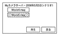
ここで、図8C中の</item>タグを参照すると、Movie4.mpgとMovie5.mpgファイルの2つのファイルが存在し、その表示名はそれぞれ「Movie4」と「Movie5」であることがわかる。 Here, referring to the </ item> tag in FIG. mpg and Movie5. It can be seen that there are two files of the mpg file, and their display names are “Movie4” and “Movie5”, respectively.
さらに、</res〜>タグを参照すると、これらのファイルがMPEG2−PSフォーマットの映像ファイルであり、HTTPのGETコマンドで取得可能であることがわかる。テレビアダプタ204は、受信したBrowseレスポンス中のコンテンツリストをテレビ208に表示する。図9Cに表示画面の例を示す。
Further, referring to the </ res˜ tag, it is understood that these files are video files in the MPEG2-PS format and can be acquired by an HTTP GET command. The
ユーザがテレビアダプタ204のリモコン205を操作して、「2006年5月2日」フォルダのMovie4.mpgファイルの再生を選択する。これにより、テレビアダプタ204は、パラメータ「/20060502/Movie4.mpg」を有するHTTPのGETリクエストをカメラアダプタ201へ送信する(ステップS7)。
The user operates the
カメラアダプタ201は、HTTPのOKレスポンスで、ディレクトリ「20060502」の下のMovie4.mpgファイルをテレビアダプタ204へ送信する(ステップS8)。
The
これを受けて、テレビアダプタ204は、受信したファイルをテレビ208に再生表示する。
In response to this, the
以上説明したように、実施形態1によれば、DVDビデオカメラのDVDディスク上の映像ファイルを、コンピュータによるアクセス可能なファイルシステムフォーマットの階層的なコンテンツ情報に展開する。そして、コンテンツ情報に基づいて、ネットワーク上のクライアント端末からアクセス可能にするネットワーク公開用フォーマットのコンテンツ情報を作成する。 As described above, according to the first embodiment, a video file on a DVD disk of a DVD video camera is expanded into hierarchical content information in a file system format accessible by a computer. Then, based on the content information, content information in a network public format that can be accessed from a client terminal on the network is created.
これにより、ネットワークを介してカメラアダプタに接続されているクライアント端末から、カメラアダプタ上のコンテンツ情報をアクセスすることが可能となる。
<実施形態2>
実施形態1では、カメラアダプタ201に設定されている区切り情報は撮影日付であるが、本発明はこれに限定されるものではない。実施形態2では、DVDビデオカメラ202から取得できるカメラの電源オン/オフのタイミング情報を区切り情報として使用する構成について説明する。
As a result, the content information on the camera adapter can be accessed from a client terminal connected to the camera adapter via the network.
<
In the first embodiment, the delimiter information set in the
また、実施形態1では、カメラアダプタ201が使用する区切り情報は、あらかじめカメラアダプタ201に設定してあるものとしているが、その設定をクライアント端末(例えば、テレビアダプタ204や206)から設定可能としても良い。例えば、カメラアダプタ201が保持している区切り情報の選択肢の中から、テレビアダプタ204をリモコン205で操作して、ネットワーク経由で設定するようにしてもよい。
In the first embodiment, the delimiter information used by the
実施形態2では、使用するDVDビデオカメラ202は、あとから利用するための区切り情報を作成し、それを区切り情報格納用のファイルである区切り情報ファイルに格納する機能を有するものとする。この区切り情報ファイルを読み込むことにより、カメラアダプタ201はDVDビデオカメラ202から区切り情報を取得することができる。取得した区切り情報の選択肢をネットワークに公開し、クライアント端末からの選択指示により、カメラアダプタ201に設定する。
In the second embodiment, it is assumed that the
以下、実施形態2におけるテレビアダプタ204/208とカメラアダプタ201の間の通信シーケンスを、図10及び図11A及び図11Bを用いて説明する。
Hereinafter, a communication sequence between the
図10は本発明の実施形態2のテレビアダプタとカメラアダプタの間の、区切り情報の取得、コンテンツリストの取得及びコンテンツの取得に関する通信シーケンスを示す図である。図11A及び図11Bは本発明の実施形態2のクライアント端末の区切り情報設定画面の表示例を示す図である。 FIG. 10 is a diagram showing a communication sequence regarding acquisition of delimiter information, acquisition of a content list, and acquisition of content between the television adapter and the camera adapter according to the second embodiment of the present invention. 11A and 11B are diagrams showing display examples of the delimiter information setting screen of the client terminal according to the second embodiment of the present invention.
以下、ここでは、テレビアダプタ204とカメラアダプタ201間の通信を行う場合を例に挙げて説明する。
Hereinafter, a case where communication between the
テレビアダプタ204では、テレビ208に図11Aのサーバ設定画面を表示する。このサーバ設定画面では、サーバとして、「Myカメラサーバ」と「ディスクサーバ」が存在する。ここで、「Myカメラサーバ」はカメラアダプタ201に対応し、「ディスクサーバ」は、ネットワーク上のストレージサーバ(不図示)に対応する。
The
ユーザがリモコン205を操作して、カメラアダプタ201である「Myカメラサーバ」を選択する。これにより、テレビアダプタ204は、カメラアダプタ201に区切り情報取得コマンドを送信する(ステップS11)。このコマンド送信には、SOAP(Simple Object ACcess Protocol)メッセージの仕組みを利用する。
The user operates the
カメラアダプタ201は、区切り情報の選択肢を含む区切り情報取得レスポンスをテレビアダプタ204へ送信する(ステップS12)。
The
テレビアダプタ204は、受信した区切り情報取得レスポンス中の選択肢を含む区切り情報選択画面(図11B)をテレビ208に表示する。ユーザがリモコン205を操作して、「電源ON/OFF」を区切り情報として選択して、設定ボタンを押すと、テレビアダプタ204は、区切り情報設定コマンドをカメラアダプタ201へ送信する(ステップS13)。このコマンド送信には、SOAP(Simple Object ACcess Protocol)メッセージの仕組みを利用する。
The
これを受けて、カメラアダプタ201は、設定OKを示す区切り情報設定レスポンスをテレビアダプタ204へ送信する(ステップS14)。以上により、区切り情報の設定シーケンスを完了する。その後、ユーザは、リモコン205を操作することにより、設定した区切り情報によって分類されたコンテンツ情報をカメラアダプタ201から受信し、テレビ208に表示させることができる。
In response to this, the
その後、表示されているコンテンツ情報に対して、カメラアダプタ201は、ルートディレクトリのコンテンツリストを含むBrowseレスポンスを生成して、テレビアダプタ204へ送信する(ステップS15)。
Thereafter, for the displayed content information, the
テレビアダプタ204は、受信したBrowseレスポンス中のコンテンツリストのフォルダの表示用タイトルを、テレビ208に表示する。ユーザがテレビアダプタ204のリモコン205を操作して、「Scenario1」フォルダを選択する。これを受けて、テレビアダプタ204は、「ObjectID=/Scenario1」を指定するBrowseコマンドをカメラアダプタ201へ送信する(ステップS17)。
The
カメラアダプタ201は、「ObjectID=/Scenario1」を指定するBrowseコマンドをテレビアダプタ204から受信すると、表示対象が「Scenario1」フォルダであることを解釈する。そこで、カメラアダプタ201は、「Scenario1」フォルダのコンテンツリストを含むBrowseレスポンスを生成して、テレビアダプタ204へ送信する(ステップS18)。
When the
次に、区切り情報の設定をクライアント端末から行う場合のカメラアダプタ201の処理を、図12を用いて説明する。
Next, processing of the
図12は本発明の実施形態2のカメラアダプタの処理を示すフローチャートである。 FIG. 12 is a flowchart showing the processing of the camera adapter according to the second embodiment of the present invention.
尚、ここでは、DVDビデオカメラのフォーマットがDVD−Videoフォーマットであると認識した場合の例で説明する。また、この処理は、カメラアダプタ201のシステムコントローラ100が、カメラアダプタ201内の各種構成要素を制御することで実現する。また、クライアント端末は、テレビアダプタ204であるとする。
Here, an example in which the format of the DVD video camera is recognized as the DVD-Video format will be described. This process is realized by the system controller 100 of the
カメラアダプタ201は、区切り情報のデフォルトの選択肢として、撮影日時を選択肢に設定し、カメラアダプタ201で使用する区切り情報の初期設定を撮影日時にセットする(ステップS201)。この初期設定は、クライアント端末からの設定指示がない場合に使用される。
The
カメラアダプタ201は、DVDビデオカメラ202から取得したファイルの中に、区切り情報ファイルがあるか否かを判定する(ステップS202)。ここで、区切り情報ファイルは、「SEPARATE.EXT」という名前のファイルであるとする。
The
区切り情報ファイルがない場合(ステップS202でNO)、ステップS204に進む。一方、区切り情報ファイルがある場合(ステップS202でYES)、カメラアダプタ201は、取得したファイルから区切り情報ファイルを取得し、選択肢に追加する(ステップS203)。
If there is no delimiter information file (NO in step S202), the process proceeds to step S204. On the other hand, if there is a delimiter information file (YES in step S202), the
図13にDVDビデオカメラ202が作成した区切り情報ファイルの一例を示す。<SeparatorList>の開始タグから終了タグに囲まれた行に、個々の区切り情報が<Separator>タグで記述されている。この例では、DVDビデオカメラ202が生成する区切り情報として、電源オン/オフ情報が利用できることを示している。この場合、カメラアダプタ201は、区切り情報として電源オン/オフ情報を選択肢に追加する。
FIG. 13 shows an example of a delimiter information file created by the
図12の説明に戻る。 Returning to the description of FIG.
カメラアダプタ201は、区切り情報の選択肢をネットワークに公開する(ステップS204)。ここでは、DVDビデオカメラ202から電源オン/オフ情報を区切り情報として取得したので、撮影日付と電源オン/オフの2つがカメラアダプタ201に設定する区切り情報の候補として公開される。
The
カメラアダプタ201は、クライアント端末から区切り情報設定要求の有無を判定する(ステップS205)。区切り情報設定要求がない場合(ステップS205でNO)、ステップS207に進む。一方、区切り情報設定要求がある場合(ステップS205でYES)、カメラアダプタ201は、指定された区切り情報をカメラアダプタ201に設定する(ステップS206)。ここでは、クライアント端末から電源オン/オフ情報を区切り情報として指示されたものとすると、カメラアダプタ201で使用する区切り情報に電源オン/オフ情報が設定される。
The
次に、カメラアダプタ201は、クライアント端末からのコンテンツ情報取得要求の有無を判定する(ステップS207)。コンテンツ情報取得要求がない場合(ステップS207でNO)、ステップS205に戻る。一方、コンテンツ情報取得要求がある場合(ステップS207でYES)、ステップS208に進む。そして、カメラアダプタ201は、タイトル情報とチャプタ情報及び区切り情報(電源オン/オフ情報)をファイルから抽出し、電源オン/オフ情報で分類してフォルダ構成を作成する(ステップS208)。
Next, the
尚、図13の区切り情報ファイルの例で、「#」文字から始まる行はコメント行である。5行目から始まる<event>タグに個々のイベントが記述されている。<event>タグの「information」属性はイベント種別を、「attrib」属性はイベント詳細情報を、「date」属性はイベントの発生日を、「time」属性はイベント発生時刻を示している。 In the example of the delimiter information file in FIG. 13, the line starting with the “#” character is a comment line. Each event is described in an <event> tag starting from the fifth line. The “information” attribute of the <event> tag indicates the event type, the “attribute” attribute indicates the detailed event information, the “date” attribute indicates the event occurrence date, and the “time” attribute indicates the event occurrence time.
例えば、5行目のイベントは、2006年5月3日の午後1時ちょうどにDVDビデオカメラ202の電源が投入されたことを示している。また、6行目は、午後1時5分ちょうどに撮影が開始されたことを、7行目は午後1時5分20秒に撮影が停止されたことをそれぞれ示している。その後、2回の撮影が繰り返され、午後1時13分50秒に電源が切断されたことを示している。以下、読み進めていくことにより、電源オン/オフ操作と撮影操作とのタイミング関係が明らかになる。
For example, the event in the fifth row indicates that the power of the
図14Aに、カメラアダプタ201が拡張子VROの映像ファイル、拡張子IFOの関連情報ファイル及び拡張子EXTの区切り情報ファイルから抽出する情報の例を示している。個々の撮影シーンをチャプタとして表現し、それに対して、撮影日情報と、電源オン/オフ情報が関連付けられている。チャプタ1、チャプタ4、及びチャプタ6は電源投入後最初に撮影されている。また、チャプタ3、チャプタ5及びチャプタ10を撮影した後に電源がオフされている。
FIG. 14A shows an example of information extracted by the
図14Bに、電源オン/オフ情報を区切り情報として分類を適用した場合の階層構造(ディレクトリ及びファイル構成)作成例を示す。3回の電源オン/オフに対して「Scenario1」〜「Scenario3」フォルダの3つのフォルダが作成され、それぞれの「Scenario」フォルダの下に個々の撮影シーンに対するMPEG2ファイルが作成される。
FIG. 14B shows an example of creating a hierarchical structure (directory and file structure) when classification is applied using power on / off information as delimiter information. Three folders of “
図12の説明に戻る。 Returning to the description of FIG.
作成したフォルダ構成に基づいて、ネットワーク公開用フォーマットでコンテンツ情報を作成し、ネットワークに公開する(ステップS210)。 Based on the created folder structure, content information is created in a network publication format and published to the network (step S210).
次に、電源オン/オフ情報を区切り情報してカメラアダプタ201に設定する場合のテレビアダプタの表示画面例を、図15A〜図15Dを用いて説明する。図15Aに示す先頭画面では、1回の電源オンから電源オフまでを一つのシナリオとして、シナリオ1からシナリオ3までの3つの項目が表示されている。
Next, an example of the display screen of the television adapter when the power on / off information is set as the delimiter information in the
ユーザがリモコン205を操作してシナリオ3を選択すると、図15Bに示すように、最後の電源オン/オフ操作の間に連続して撮影された5つの撮影シーンがそれぞれMPEG2ファイルとして表示される。ここで、「Movie6.mpg」の再生を選択すると、最後に電源を入れてから最初に撮影したシーンの再生が開始される。あるいは、図15Aの画面でシナリオ3の再生を選択することにより、連続して撮影した5つのシーンを続けて再生することができる。
When the user operates the
ここで比較のために、同じ撮影内容を単純に撮影日付で分類した場合の表示画面例を図15C、図15Dに示す。図15C中の下向き三角印及び図15D中の上向き三角印は、画面内に全ての項目が表示しきれない場合に、これを選択して表示をスクロールさせるための操作ボタンである。撮影日付で単純に分類した場合よりも、電源オン/オフ情報を利用して分類したほうが、より画面も見易く、操作性も向上している。 For comparison, FIGS. 15C and 15D show examples of display screens when the same shooting content is simply classified by shooting date. A downward triangle mark in FIG. 15C and an upward triangle mark in FIG. 15D are operation buttons for selecting and scrolling the display when not all items can be displayed on the screen. The screen is easier to see and the operability is improved by using the power-on / off information to classify the images than when the images are simply classified by shooting date.
以上説明したように、実施形態2によれば、実施形態1で説明した効果に加えて、用途や目的に応じた区切り情報を設定することが可能となるので、よりユーザが意図する分類方法で分類されたコンテンツ情報の操作が可能となる。 As described above, according to the second embodiment, in addition to the effects described in the first embodiment, it is possible to set delimiter information according to the purpose and purpose. The classified content information can be operated.
<実施形態3>
上記実施形態では、DVDビデオカメラ202が作成する区切り情報は、拡張子EXTの独自ファイルに格納したが、それ以外の方法で格納してもよい。例えば、静止画撮影データ格納用の記録媒体である、DVDビデオカメラ202に接続されているSDメモリカード内に格納しても良い。あるいは、DVD規格で規定されている拡張子IFOの関連情報ファイルの中に専用データフィールドを設けて、そこに区切り情報を格納しても良い。
<
In the above embodiment, the delimiter information created by the
また、DVDビデオカメラ202が作成する区切り情報は、DVDビデオカメラ202の電源オン/オフ情報以外にも、様々な情報を利用することができる。例えば、DVDディスクに付けられたタイトル情報の有無や種類、撮影時のDVDビデオカメラ202の撮影モード、あるいはDVDビデオカメラ202の所定のキーが押されたか否か等の情報を用いても良い。
In addition to the power on / off information of the
また、複数の区切り情報を組み合わせて、より詳細に分類することも可能である。複数の区切り情報を用いる場合には、区切り情報に優先順位を設けて、階層構造を構成することもできる。そのような構成を実現するための設定画面例を、図16に示す。 It is also possible to classify in more detail by combining a plurality of pieces of delimiter information. When a plurality of pieces of delimiter information are used, a priority structure can be provided for the delimiter information to form a hierarchical structure. An example of a setting screen for realizing such a configuration is shown in FIG.
図16では、撮影開始日を第一優先の区切り情報、カメラの電源オン/オフを第二優先の区切り情報として設定している。これを図14Aに示す例に対して適用すると、図17に示すようなディレクトリ及びファイル構成でコンテンツ情報を作成できる。ここでは、ルートディレクトリの下に二つの日付フォルダが存在する。 In FIG. 16, the shooting start date is set as first priority separator information, and the camera power on / off is set as second priority separator information. When this is applied to the example shown in FIG. 14A, content information can be created with a directory and file structure as shown in FIG. Here, there are two date folders under the root directory.
この場合のテレビアダプタの表示画面例を図18に示す。図18Aでは、「2006年5月3日」と「2006年5月5日」フォルダが表示されている。「2006年5月5日」を選択すると、図18Bに示すように、さらに「シナリオ2」と「シナリオ3」の2つのサブフォルダが表示される。ここで、「シナリオ3」フォルダを選択すると、図18Cに示すように「Movie6.mpg」〜「Movie10.mpg」までの5つの映像ファイルが表示される。
A display screen example of the television adapter in this case is shown in FIG. In FIG. 18A, “May 3, 2006” and “May 5, 2006” folders are displayed. When “May 5, 2006” is selected, as shown in FIG. 18B, two subfolders “
ここで、映像ファイルの再生の方法としては、例えば、「シナリオ3」フォルダを選択して再生を選択すると、「シナリオ3」フォルダに含まれるファイルを全て再生することができる。また、「2006年5月5日」フォルダを選択して再生を選択すると、「2006年5月5日」の下の「シナリオ2」と「シナリオ3」フォルダに含まれるファイルを全て再生することができる。
Here, as a method of reproducing the video file, for example, when the “
また、複数の区切り情報を同一の優先順位に設定することもできる。例えば、DVDビデオカメラの所定のボタンを押下した情報を区切り情報として撮影を行い、図19に示す情報をDVDビデオカメラ202から取得できたとする。この例では、5月4日にボタンを押下して撮影を開始して3つのシーンを撮影し、さらに5月5日に2つのシーンを撮影している。その後、再度ボタンを押下してシナリオの区切りとし、5つのシーンを撮影している。 A plurality of pieces of delimiter information can be set to the same priority. For example, it is assumed that information obtained by pressing a predetermined button of a DVD video camera is taken as delimiter information, and the information shown in FIG. In this example, the button is pressed on May 4 to start shooting, three scenes are shot, and two scenes are shot on May 5. After that, the button is pressed again as a scenario break, and five scenes are shot.
この場合に、ボタン押下情報と撮影日情報を同一優先順位とした場合には、図20に示すディレクトリ及びファイル構成でコンテンツ情報を作成できる。ルートディレクトリの下に「20060504−Scenario1」、「20060505−Scenario1」及び「20060505−Scenario2」の3つのフォルダが存在する。 In this case, if the button press information and the shooting date information have the same priority, content information can be created with the directory and file structure shown in FIG. Under the root directory, there are three folders “20060604-Scenario1”, “20066055-Scenario1”, and “20060505-Scenario2”.
この場合のテレビアダプタの表示画面例を図21に示す。図21Aでは、3つのフォルダに対応した項目が表示されている。ここで「2006年5月4日シナリオ1」を選択すると、図21Bに示すように「Movie1.mpg」〜「Movie3.mpg」までの3つのコンテンツが表示される。また、「2006年5月5日シナリオ1」を選択すると、図21Cに示すように「Movie4.mpg」と「Movie5.mpg」の2つのコンテンツが表示される。
An example of the display screen of the television adapter in this case is shown in FIG. In FIG. 21A, items corresponding to three folders are displayed. Here, when “May 4, 2006
ここで、例えば、「2006年5月5日シナリオ1」フォルダを選択して、再生を選択することにより、「2006年5月5日シナリオ1」フォルダの下にある2つのファイルを全て再生することが可能である。
Here, for example, by selecting the “May 5, 2006
以上説明したように、実施形態3によれば、実施形態1で説明した効果に加えて、用途や目的に応じた複数種類の区切り情報を任意に設定することが可能となるので、よりユーザが意図する分類方法で分類されたコンテンツ情報の操作が可能となる。
<実施形態4>
上記実施形態1〜3では、カメラアダプタ201が、設定された区切り情報により分類して作成したフォルダ構成やファイル構成は、一旦作成したら変更されないものであるかのように説明してきたが、本発明はこれに限定されるものではない。例えば、作成したMPEG2ファイルの実体は一つのフォルダの下に全て作成しておき、ファイルの実体へのリンクをフォルダ上に作成することにより、リンクを作成し直すだけでデータの移動を伴わずにダイナミックに論理的な構成を変更することも可能である。
As described above, according to the third embodiment, in addition to the effects described in the first embodiment, it is possible to arbitrarily set a plurality of types of delimiter information according to applications and purposes. The content information classified by the intended classification method can be operated.
<
In the first to third embodiments, the folder configuration and the file configuration created by the
以上、実施形態例を詳述したが、本発明は、例えば、システム、装置、方法、プログラムもしくは記憶媒体等としての実施態様をとることが可能である。具体的には、複数の機器から構成されるシステムに適用しても良いし、また、一つの機器からなる装置に適用しても良い。 Although the embodiment has been described in detail above, the present invention can take an embodiment as a system, apparatus, method, program, storage medium, or the like. Specifically, the present invention may be applied to a system composed of a plurality of devices, or may be applied to an apparatus composed of a single device.
尚、本発明は、前述した実施形態の機能を実現するソフトウェアのプログラム(実施形態では図に示すフローチャートに対応したプログラム)を、システムあるいは装置に直接あるいは遠隔から供給する。そして、そのシステムあるいは装置のコンピュータが該供給されたプログラムコードを読み出して実行することによっても達成される場合を含む。 In the present invention, a software program (in the embodiment, a program corresponding to the flowchart shown in the drawing) that realizes the functions of the above-described embodiments is directly or remotely supplied to a system or apparatus. In addition, this includes a case where the system or the computer of the apparatus is also achieved by reading and executing the supplied program code.
従って、本発明の機能処理をコンピュータで実現するために、該コンピュータにインストールされるプログラムコード自体も本発明を実現するものである。つまり、本発明は、本発明の機能処理を実現するためのコンピュータプログラム自体も含まれる。 Accordingly, since the functions of the present invention are implemented by computer, the program code installed in the computer also implements the present invention. In other words, the present invention includes a computer program itself for realizing the functional processing of the present invention.
その場合、プログラムの機能を有していれば、オブジェクトコード、インタプリタにより実行されるプログラム、OSに供給するスクリプトデータ等の形態であっても良い。 In that case, as long as it has the function of a program, it may be in the form of object code, a program executed by an interpreter, script data supplied to the OS, or the like.
プログラムを供給するための記録媒体としては、例えば、フロッピー(登録商標)ディスク、ハードディスク、光ディスクがある。また、更に、記録媒体としては、光磁気ディスク、MO、CD−ROM、CD−R、CD−RW、磁気テープ、不揮発性のメモリカード、ROM、DVD(DVD−ROM,DVD−R)などがある。 Examples of the recording medium for supplying the program include a floppy (registered trademark) disk, a hard disk, and an optical disk. Further, as a recording medium, magneto-optical disk, MO, CD-ROM, CD-R, CD-RW, magnetic tape, nonvolatile memory card, ROM, DVD (DVD-ROM, DVD-R), etc. is there.
その他、プログラムの供給方法としては、クライアントコンピュータのブラウザを用いてインターネットのホームページに接続する。そして、その接続先のホームページから本発明のコンピュータプログラムそのもの、もしくは圧縮され自動インストール機能を含むファイルをハードディスク等の記録媒体にダウンロードすることによっても供給できる。また、本発明のプログラムを構成するプログラムコードを複数のファイルに分割し、それぞれのファイルを異なるホームページからダウンロードすることによっても実現可能である。つまり、本発明の機能処理をコンピュータで実現するためのプログラムファイルを複数のユーザに対してダウンロードさせるWWWサーバも、本発明に含まれるものである。 As another program supply method, a browser on a client computer is used to connect to an Internet home page. Then, the computer program itself of the present invention or a compressed file including an automatic installation function can be downloaded from a homepage of the connection destination to a recording medium such as a hard disk. It can also be realized by dividing the program code constituting the program of the present invention into a plurality of files and downloading each file from a different homepage. That is, a WWW server that allows a plurality of users to download a program file for realizing the functional processing of the present invention on a computer is also included in the present invention.
また、本発明のプログラムを暗号化してCD−ROM等の記憶媒体に格納してユーザに配布し、所定の条件をクリアしたユーザに対し、インターネットを介してホームページから暗号化を解く鍵情報をダウンロードさせる。そして、その鍵情報を使用することにより暗号化されたプログラムを実行してコンピュータにインストールさせて実現することも可能である。 In addition, the program of the present invention is encrypted, stored in a storage medium such as a CD-ROM, distributed to users, and key information for decryption is downloaded from a homepage via the Internet to users who have cleared predetermined conditions. Let me. It is also possible to execute the encrypted program by using the key information and install the program on a computer.
また、コンピュータが、読み出したプログラムを実行することによって、前述した実施形態の機能が実現される。また、そのプログラムの指示に基づき、コンピュータ上で稼動しているOSなどが、実際の処理の一部または全部を行い、その処理によっても前述した実施形態の機能が実現され得る。 Further, the functions of the above-described embodiments are realized by the computer executing the read program. Further, based on the instructions of the program, the OS running on the computer performs part or all of the actual processing, and the functions of the above-described embodiments can be realized by the processing.
さらに、記録媒体から読み出されたプログラムが、コンピュータに挿入された機能拡張ボードやコンピュータに接続された機能拡張ユニットに備わるメモリに書き込まれる。その後、そのプログラムの指示に基づき、その機能拡張ボードや機能拡張ユニットに備わるCPUなどが実際の処理の一部または全部を行い、その処理によっても前述した実施形態の機能が実現される。 Further, the program read from the recording medium is written in a memory provided in a function expansion board inserted into the computer or a function expansion unit connected to the computer. Thereafter, the CPU of the function expansion board or function expansion unit performs part or all of the actual processing based on the instructions of the program, and the functions of the above-described embodiments are realized by the processing.
100 システムコントローラ
101 フラッシュメモリ
102 RAM
103 USBコネクタ
104 USBホストコントローラ
105 AC電源コネクタ
106 電源回路
107 LANコントローラ
108 LANコネクタ
109 ハードディスク
110 ハードディスクインタフェース
111 システムバス
112 I/Oポート制御回路
113 ソフトスイッチ
114 LED
100
103
Claims (8)
前記撮像装置から、前記ディスク記録媒体に記録された映像ファイルを取得する取得手段と、
前記取得手段で取得した映像ファイルを区切るための区切り情報を設定する設定手段と、
前記取得手段で取得した映像ファイルのリストとして、前記映像ファイルを前記設定手段で設定した区切り情報に基づいて分類した階層的なディレクトリ構成及びファイル構成からなる第1コンテンツ情報を作成する第1作成手段と、
前記第1作成手段で作成した第1コンテンツ情報に基づいて、ネットワーク公開用フォーマットの第2コンテンツ情報を作成する第2作成手段と、
前記第1作成手段で作成した第1コンテンツ情報と、前記取得手段で取得した映像ファイルとに基づいて、ネットワーク公開用フォーマットの映像ファイルを作成する映像ファイル作成手段と、
前記第2作成手段で作成した第2コンテンツ情報を前記ネットワーク上に公開する公開手段と、
前記公開手段で公開した第2コンテンツ情報に基づいてネットワーク上のクライアント端末から要求された映像ファイルを、前記クライアント端末へ配信する配信手段と
を備えることを特徴とするアダプタ装置。 An adapter device that connects an image pickup apparatus having a disk recording unit that records video according to a specific format to a disk recording medium, and distributes a video file recorded on the disk recording medium of the image pickup apparatus to a client terminal on a network. There,
Obtaining means for obtaining a video file recorded on the disk recording medium from the imaging device;
Setting means for setting delimiter information for delimiting the video file obtained by the obtaining means;
First creation means for creating , as a list of video files acquired by the acquisition means, first content information having a hierarchical directory structure and file structure in which the video files are classified based on delimiter information set by the setting means. When,
Based on the first content information created by the first creation means, second creation means for creating second content information in a network release format;
Video file creation means for creating a video file in a network release format based on the first content information created by the first creation means and the video file obtained by the acquisition means;
Publishing means for publishing the second content information created by the second creating means on the network;
An adapter device comprising: distribution means for distributing a video file requested from a client terminal on a network to the client terminal based on the second content information published by the publication means.
前記認識手段で認識した記録フォーマットに従って、前記撮像装置から取得する映像ファイルを解釈する解釈手段とを更に備え、
前記第1作成手段は、前記解釈手段の解釈結果と前記区切り情報に基づいて、前記第1コンテンツ情報を作成する
ことを特徴とする請求項1に記載のアダプタ装置。 Recognizing means for recognizing the recording format of the video file recorded on the disk recording medium;
Interpreting means for interpreting a video file acquired from the imaging device according to the recording format recognized by the recognition means,
The adapter device according to claim 1, wherein the first creation unit creates the first content information based on an interpretation result of the interpretation unit and the delimiter information .
ことを特徴とする請求項2に記載のアダプタ装置。 The adapter device according to claim 2, wherein the recording format is either a DVD-Video format or a DVD-VR format.
ことを特徴とする請求項1に記載のアダプタ装置。 It said first generating means, as the list, the first content information comprising a plurality of shooting scenes included in the video files acquired by the acquisition means from the hierarchical directory structure and file structure were classified on the basis of the delimiter information The adapter device according to claim 1, wherein the adapter device is created.
ことを特徴とする請求項1に記載のアダプタ装置。 It said first generating means, as the list, first content to be from the obtained plurality of the plurality of shooting scenes included in the video file has been classified on the basis of the delimiter information hierarchical directory structure and file structure by the acquisition unit The adapter device according to claim 1, wherein information is created.
前記複数種類の区切り情報から、前記第1作成手段で用いる区切り情報を選択する選択手段と
を更に備えることを特徴とする請求項1に記載のアダプタ装置。 Storage means for storing a plurality of types of the delimiter information;
The adapter device according to claim 1 , further comprising: a selecting unit that selects delimiter information used by the first creation unit from the plurality of types of delimiter information.
前記アダプタ装置の取得手段が、前記撮像装置から、前記ディスク記録媒体に記録された映像ファイルを取得する取得工程と、
前記アダプタ装置の設定手段が、前記取得工程で取得した映像ファイルを区切るための区切り情報を設定する設定工程と、
前記アダプタ装置の第1作成手段が、前記取得工程で取得した映像ファイルのリストとして、前記映像ファイルを前記設定工程で設定した区切り情報に基づいて分類した階層的なディレクトリ構成及びファイル構成からなる第1コンテンツ情報を作成する第1作成工程と、
前記アダプタ装置の第2作成手段が、前記第1作成工程で作成した第1コンテンツ情報に基づいて、ネットワーク公開用フォーマットの第2コンテンツ情報を作成する第2作成工程と、
前記アダプタ装置の映像ファイル作成手段が、前記第1作成工程で作成した第1コンテンツ情報と、前記取得工程で取得した映像ファイルとに基づいて、ネットワーク公開用フォーマットの映像ファイルを作成する映像ファイル作成工程と、
前記アダプタ装置の公開手段が、前記第2作成工程で作成した第2コンテンツ情報を前記ネットワーク上に公開する公開工程と、
前記アダプタ装置の配信手段が、前記公開工程で公開した第2コンテンツ情報に基づいてネットワーク上のクライアント端末から要求された映像ファイルを、前記クライアント端末へ配信する配信工程と
を備えることを特徴とするアダプタ装置の制御方法。 An adapter device for connecting an image pickup apparatus having a disk recording unit for recording a video according to a specific format to a disk recording medium, and distributing a video file recorded on the disk recording medium of the image pickup apparatus to a client terminal on a network A control method,
The acquisition unit of the adapter device acquires an image file recorded on the disk recording medium from the imaging device;
A setting step in which the setting unit of the adapter device sets delimiter information for delimiting the video file acquired in the acquisition step;
The first creation unit of the adapter device includes a hierarchical directory configuration and file configuration in which the video files are classified based on the delimiter information set in the setting step as a list of video files acquired in the acquisition step. A first creation step for creating one content information;
A second creation step in which the second creation means of the adapter device creates the second content information in a network release format based on the first content information created in the first creation step;
Video file creating means of the adapter device, the first content information created by said first creation step, on the basis of the image files acquired by the acquisition step, creating the image file to create a video file of a format for network publishing Process,
A publishing step in which the publishing means of the adapter device publishes the second content information created in the second creating step on the network;
The distribution unit of the adapter device includes a distribution step of distributing a video file requested from a client terminal on a network to the client terminal based on the second content information disclosed in the disclosure step. Control method of adapter device.
前記撮像装置から、前記ディスク記録媒体に記録された映像ファイルを取得する取得工程と、
前記取得工程で取得した映像ファイルを区切るための区切り情報を設定する設定工程と、
前記取得工程で取得した映像ファイルのリストとして、前記映像ファイルを前記設定工程で設定した区切り情報に基づいて分類した階層的なディレクトリ構成及びファイル構成からなる第1コンテンツ情報を作成する第1作成工程と、
前記第1作成工程で作成した第1コンテンツ情報に基づいて、ネットワーク公開用フォーマットの第2コンテンツ情報を作成する第2作成工程と、
前記第1作成工程で作成した第1コンテンツ情報と、前記取得工程で取得した映像ファイルとに基づいて、ネットワーク公開用フォーマットの映像ファイルを作成する映像ファイル作成工程と、
前記第2作成工程で作成した第2コンテンツ情報を前記ネットワーク上に公開する公開工程と、
前記公開工程で公開した第2コンテンツ情報に基づいてネットワーク上のクライアント端末から要求された映像ファイルを、前記クライアント端末へ配信する配信工程と
をコンピュータに実行させることを特徴とするコンピュータプログラム。 An adapter device for connecting an image pickup apparatus having a disk recording unit for recording a video according to a specific format to a disk recording medium, and distributing a video file recorded on the disk recording medium of the image pickup apparatus to a client terminal on a network A computer program for causing a computer to execute control,
An acquisition step of acquiring a video file recorded on the disk recording medium from the imaging device;
A setting step for setting delimiter information for delimiting the video file acquired in the acquisition step;
As a list of video files acquired in the acquisition step, a first creation step of generating first content information including a hierarchical directory configuration and file configuration in which the video file is classified based on the delimiter information set in the setting step When,
A second creation step of creating second content information in a format for network release based on the first content information created in the first creation step;
A video file creation step for creating a video file in a network release format based on the first content information created in the first creation step and the video file obtained in the acquisition step;
A publication step of publishing the second content information created in the second creation step on the network;
A computer program causing a computer to execute a distribution step of distributing a video file requested from a client terminal on a network to the client terminal based on the second content information disclosed in the disclosure step.
Priority Applications (2)
| Application Number | Priority Date | Filing Date | Title |
|---|---|---|---|
| JP2007211930A JP5252854B2 (en) | 2007-08-15 | 2007-08-15 | Adapter device, control method therefor, and computer program |
| US12/186,970 US8395680B2 (en) | 2007-08-15 | 2008-08-06 | Adapter apparatus connected to an image capturing apparatus and delivering video files thereof to a client apparatus, control method thereof, and computer program |
Applications Claiming Priority (1)
| Application Number | Priority Date | Filing Date | Title |
|---|---|---|---|
| JP2007211930A JP5252854B2 (en) | 2007-08-15 | 2007-08-15 | Adapter device, control method therefor, and computer program |
Publications (3)
| Publication Number | Publication Date |
|---|---|
| JP2009049574A JP2009049574A (en) | 2009-03-05 |
| JP2009049574A5 JP2009049574A5 (en) | 2010-09-16 |
| JP5252854B2 true JP5252854B2 (en) | 2013-07-31 |
Family
ID=40363036
Family Applications (1)
| Application Number | Title | Priority Date | Filing Date |
|---|---|---|---|
| JP2007211930A Expired - Fee Related JP5252854B2 (en) | 2007-08-15 | 2007-08-15 | Adapter device, control method therefor, and computer program |
Country Status (2)
| Country | Link |
|---|---|
| US (1) | US8395680B2 (en) |
| JP (1) | JP5252854B2 (en) |
Families Citing this family (7)
| Publication number | Priority date | Publication date | Assignee | Title |
|---|---|---|---|---|
| JP4939307B2 (en) * | 2007-05-29 | 2012-05-23 | キヤノン株式会社 | Adapter device, control method therefor, and computer program |
| JP5317835B2 (en) * | 2009-06-03 | 2013-10-16 | キヤノン株式会社 | Content attribute information providing apparatus, content attribute information providing method, and computer program |
| JP5460164B2 (en) * | 2009-07-24 | 2014-04-02 | キヤノン株式会社 | Information processing apparatus, control method, and program |
| JP2012213111A (en) * | 2011-03-31 | 2012-11-01 | Sony Corp | Communication system, communication device, and communication method |
| CN102811377B (en) * | 2012-07-06 | 2015-05-13 | 宇龙计算机通信科技(深圳)有限公司 | Realization method of cloud end remote controller and remote control system |
| CN103888527B (en) * | 2014-03-13 | 2017-11-07 | 小米科技有限责任公司 | data sharing method and device |
| US9705743B2 (en) | 2014-03-13 | 2017-07-11 | Xiaomi Inc. | Method and device for sharing data |
Family Cites Families (13)
| Publication number | Priority date | Publication date | Assignee | Title |
|---|---|---|---|---|
| JP3546662B2 (en) * | 1997-09-12 | 2004-07-28 | 日本ビクター株式会社 | Distributed home network |
| JP2001157154A (en) * | 1999-11-26 | 2001-06-08 | Sony Corp | Recording or reproducing device and reproducing device |
| GB2387087A (en) * | 2002-03-25 | 2003-10-01 | Sony Uk Ltd | System |
| JP4228141B2 (en) | 2003-07-09 | 2009-02-25 | 喜一郎 清野 | UHF multi-element antenna elevation setting attachment device |
| JP4708733B2 (en) | 2004-05-21 | 2011-06-22 | キヤノン株式会社 | Imaging device |
| US7548259B2 (en) * | 2004-08-12 | 2009-06-16 | Microsoft Corporation | System and method for producing a higher resolution still image from video information |
| JP2006099840A (en) | 2004-09-28 | 2006-04-13 | Konica Minolta Photo Imaging Inc | Information recording/reproducing device, program, and information recording medium |
| US20060092771A1 (en) * | 2004-10-29 | 2006-05-04 | Eastman Kodak Company | Automated method and system for creating an image storage device for playback on a playback mechanism |
| JP2007013879A (en) * | 2005-07-04 | 2007-01-18 | Canon Inc | Multimedia data processing apparatus and multimedia data processing method |
| JP2007049332A (en) * | 2005-08-09 | 2007-02-22 | Sony Corp | Recording and reproducing apparatus and method, and recording apparatus and method |
| KR100717060B1 (en) * | 2005-12-05 | 2007-05-10 | 삼성전자주식회사 | Method and apparatus for utilizing dvd contents through home network |
| JP4760386B2 (en) * | 2006-01-11 | 2011-08-31 | ソニー株式会社 | Imaging display device, imaging display method, and program |
| JP2007213385A (en) * | 2006-02-10 | 2007-08-23 | Sony Corp | Information processing apparatus, information processing method, and program |
-
2007
- 2007-08-15 JP JP2007211930A patent/JP5252854B2/en not_active Expired - Fee Related
-
2008
- 2008-08-06 US US12/186,970 patent/US8395680B2/en not_active Expired - Fee Related
Also Published As
| Publication number | Publication date |
|---|---|
| US8395680B2 (en) | 2013-03-12 |
| US20090046992A1 (en) | 2009-02-19 |
| JP2009049574A (en) | 2009-03-05 |
Similar Documents
| Publication | Publication Date | Title |
|---|---|---|
| JP4021326B2 (en) | How to archive and share multimedia content | |
| JP5252854B2 (en) | Adapter device, control method therefor, and computer program | |
| KR100526177B1 (en) | Media contents file management system and method of home media center | |
| KR101367606B1 (en) | Information processing device, information processing method, and computer program | |
| US20050223037A1 (en) | File management method and apparatus for controlling assets in multimedia appliances and information recording medium therefor | |
| TW200405331A (en) | Recording medium having data structure for managing reproduction of multiple playback path video data recorded thereon and recording and reproducing methods and apparatuses | |
| EP2035969A2 (en) | Representing digital content metadata | |
| JP2005327257A (en) | File management method and apparatus for controlling asset in multimedia appliance and information recording medium therefor | |
| KR100453060B1 (en) | Methods for fixing-up lastURL representing path name and file name of asset in MPV environment | |
| JP2006260178A (en) | Content reproduction device and content reproduction method | |
| US8320732B2 (en) | Production of multimedia content | |
| JP4939307B2 (en) | Adapter device, control method therefor, and computer program | |
| KR101133125B1 (en) | A system and method to display filming time | |
| JP4375052B2 (en) | Video editing support method | |
| JP4803501B2 (en) | Content sending device | |
| JP2004171053A (en) | Data processor | |
| US8200717B2 (en) | Revision of multimedia content | |
| JP2008034954A (en) | Video recorder/reproducer and its control method and program | |
| EP2469854B1 (en) | Content uploading system, content uploading method, and content transmitting/receiving device | |
| JP4892162B2 (en) | Information recording medium and production method thereof | |
| JP2009171345A (en) | Information processing apparatus and information processing method | |
| JP2009224862A (en) | Recording program, recorder, and recording method | |
| JP2007295070A (en) | Recording device and method, program, and recording medium | |
| JP4876939B2 (en) | Information processing apparatus, information processing method, and program | |
| JP2006099840A (en) | Information recording/reproducing device, program, and information recording medium |
Legal Events
| Date | Code | Title | Description |
|---|---|---|---|
| A521 | Request for written amendment filed |
Free format text: JAPANESE INTERMEDIATE CODE: A523 Effective date: 20100803 |
|
| A621 | Written request for application examination |
Free format text: JAPANESE INTERMEDIATE CODE: A621 Effective date: 20100803 |
|
| A977 | Report on retrieval |
Free format text: JAPANESE INTERMEDIATE CODE: A971007 Effective date: 20120808 |
|
| A131 | Notification of reasons for refusal |
Free format text: JAPANESE INTERMEDIATE CODE: A131 Effective date: 20120810 |
|
| A521 | Request for written amendment filed |
Free format text: JAPANESE INTERMEDIATE CODE: A523 Effective date: 20121002 |
|
| TRDD | Decision of grant or rejection written | ||
| A01 | Written decision to grant a patent or to grant a registration (utility model) |
Free format text: JAPANESE INTERMEDIATE CODE: A01 Effective date: 20130318 |
|
| A61 | First payment of annual fees (during grant procedure) |
Free format text: JAPANESE INTERMEDIATE CODE: A61 Effective date: 20130416 |
|
| R151 | Written notification of patent or utility model registration |
Ref document number: 5252854 Country of ref document: JP Free format text: JAPANESE INTERMEDIATE CODE: R151 |
|
| FPAY | Renewal fee payment (event date is renewal date of database) |
Free format text: PAYMENT UNTIL: 20160426 Year of fee payment: 3 |
|
| LAPS | Cancellation because of no payment of annual fees |