JP5251560B2 - Cloth bonding equipment - Google Patents
Cloth bonding equipment Download PDFInfo
- Publication number
- JP5251560B2 JP5251560B2 JP2009023227A JP2009023227A JP5251560B2 JP 5251560 B2 JP5251560 B2 JP 5251560B2 JP 2009023227 A JP2009023227 A JP 2009023227A JP 2009023227 A JP2009023227 A JP 2009023227A JP 5251560 B2 JP5251560 B2 JP 5251560B2
- Authority
- JP
- Japan
- Prior art keywords
- adhesive
- nozzle
- supply
- cloth
- bonding apparatus
- Prior art date
- Legal status (The legal status is an assumption and is not a legal conclusion. Google has not performed a legal analysis and makes no representation as to the accuracy of the status listed.)
- Active
Links
Images


Classifications
-
- B—PERFORMING OPERATIONS; TRANSPORTING
- B29—WORKING OF PLASTICS; WORKING OF SUBSTANCES IN A PLASTIC STATE IN GENERAL
- B29C—SHAPING OR JOINING OF PLASTICS; SHAPING OF MATERIAL IN A PLASTIC STATE, NOT OTHERWISE PROVIDED FOR; AFTER-TREATMENT OF THE SHAPED PRODUCTS, e.g. REPAIRING
- B29C66/00—General aspects of processes or apparatus for joining preformed parts
- B29C66/70—General aspects of processes or apparatus for joining preformed parts characterised by the composition, physical properties or the structure of the material of the parts to be joined; Joining with non-plastics material
- B29C66/72—General aspects of processes or apparatus for joining preformed parts characterised by the composition, physical properties or the structure of the material of the parts to be joined; Joining with non-plastics material characterised by the structure of the material of the parts to be joined
- B29C66/729—Textile or other fibrous material made from plastics
-
- B—PERFORMING OPERATIONS; TRANSPORTING
- B29—WORKING OF PLASTICS; WORKING OF SUBSTANCES IN A PLASTIC STATE IN GENERAL
- B29C—SHAPING OR JOINING OF PLASTICS; SHAPING OF MATERIAL IN A PLASTIC STATE, NOT OTHERWISE PROVIDED FOR; AFTER-TREATMENT OF THE SHAPED PRODUCTS, e.g. REPAIRING
- B29C65/00—Joining or sealing of preformed parts, e.g. welding of plastics materials; Apparatus therefor
- B29C65/48—Joining or sealing of preformed parts, e.g. welding of plastics materials; Apparatus therefor using adhesives, i.e. using supplementary joining material; solvent bonding
- B29C65/4805—Joining or sealing of preformed parts, e.g. welding of plastics materials; Apparatus therefor using adhesives, i.e. using supplementary joining material; solvent bonding characterised by the type of adhesives
- B29C65/481—Non-reactive adhesives, e.g. physically hardening adhesives
- B29C65/4815—Hot melt adhesives, e.g. thermoplastic adhesives
-
- B—PERFORMING OPERATIONS; TRANSPORTING
- B29—WORKING OF PLASTICS; WORKING OF SUBSTANCES IN A PLASTIC STATE IN GENERAL
- B29C—SHAPING OR JOINING OF PLASTICS; SHAPING OF MATERIAL IN A PLASTIC STATE, NOT OTHERWISE PROVIDED FOR; AFTER-TREATMENT OF THE SHAPED PRODUCTS, e.g. REPAIRING
- B29C65/00—Joining or sealing of preformed parts, e.g. welding of plastics materials; Apparatus therefor
- B29C65/48—Joining or sealing of preformed parts, e.g. welding of plastics materials; Apparatus therefor using adhesives, i.e. using supplementary joining material; solvent bonding
- B29C65/52—Joining or sealing of preformed parts, e.g. welding of plastics materials; Apparatus therefor using adhesives, i.e. using supplementary joining material; solvent bonding characterised by the way of applying the adhesive
- B29C65/524—Joining or sealing of preformed parts, e.g. welding of plastics materials; Apparatus therefor using adhesives, i.e. using supplementary joining material; solvent bonding characterised by the way of applying the adhesive by applying the adhesive from an outlet device in contact with, or almost in contact with, the surface of the part to be joined
-
- B—PERFORMING OPERATIONS; TRANSPORTING
- B29—WORKING OF PLASTICS; WORKING OF SUBSTANCES IN A PLASTIC STATE IN GENERAL
- B29C—SHAPING OR JOINING OF PLASTICS; SHAPING OF MATERIAL IN A PLASTIC STATE, NOT OTHERWISE PROVIDED FOR; AFTER-TREATMENT OF THE SHAPED PRODUCTS, e.g. REPAIRING
- B29C66/00—General aspects of processes or apparatus for joining preformed parts
- B29C66/01—General aspects dealing with the joint area or with the area to be joined
- B29C66/05—Particular design of joint configurations
- B29C66/10—Particular design of joint configurations particular design of the joint cross-sections
- B29C66/11—Joint cross-sections comprising a single joint-segment, i.e. one of the parts to be joined comprising a single joint-segment in the joint cross-section
- B29C66/112—Single lapped joints
- B29C66/1122—Single lap to lap joints, i.e. overlap joints
-
- B—PERFORMING OPERATIONS; TRANSPORTING
- B29—WORKING OF PLASTICS; WORKING OF SUBSTANCES IN A PLASTIC STATE IN GENERAL
- B29C—SHAPING OR JOINING OF PLASTICS; SHAPING OF MATERIAL IN A PLASTIC STATE, NOT OTHERWISE PROVIDED FOR; AFTER-TREATMENT OF THE SHAPED PRODUCTS, e.g. REPAIRING
- B29C66/00—General aspects of processes or apparatus for joining preformed parts
- B29C66/40—General aspects of joining substantially flat articles, e.g. plates, sheets or web-like materials; Making flat seams in tubular or hollow articles; Joining single elements to substantially flat surfaces
- B29C66/41—Joining substantially flat articles ; Making flat seams in tubular or hollow articles
- B29C66/43—Joining a relatively small portion of the surface of said articles
-
- B—PERFORMING OPERATIONS; TRANSPORTING
- B29—WORKING OF PLASTICS; WORKING OF SUBSTANCES IN A PLASTIC STATE IN GENERAL
- B29C—SHAPING OR JOINING OF PLASTICS; SHAPING OF MATERIAL IN A PLASTIC STATE, NOT OTHERWISE PROVIDED FOR; AFTER-TREATMENT OF THE SHAPED PRODUCTS, e.g. REPAIRING
- B29C66/00—General aspects of processes or apparatus for joining preformed parts
- B29C66/80—General aspects of machine operations or constructions and parts thereof
- B29C66/81—General aspects of the pressing elements, i.e. the elements applying pressure on the parts to be joined in the area to be joined, e.g. the welding jaws or clamps
- B29C66/816—General aspects of the pressing elements, i.e. the elements applying pressure on the parts to be joined in the area to be joined, e.g. the welding jaws or clamps characterised by the mounting of the pressing elements, e.g. of the welding jaws or clamps
- B29C66/8161—General aspects of the pressing elements, i.e. the elements applying pressure on the parts to be joined in the area to be joined, e.g. the welding jaws or clamps characterised by the mounting of the pressing elements, e.g. of the welding jaws or clamps said pressing elements being supported or backed-up by springs or by resilient material
-
- B—PERFORMING OPERATIONS; TRANSPORTING
- B29—WORKING OF PLASTICS; WORKING OF SUBSTANCES IN A PLASTIC STATE IN GENERAL
- B29C—SHAPING OR JOINING OF PLASTICS; SHAPING OF MATERIAL IN A PLASTIC STATE, NOT OTHERWISE PROVIDED FOR; AFTER-TREATMENT OF THE SHAPED PRODUCTS, e.g. REPAIRING
- B29C66/00—General aspects of processes or apparatus for joining preformed parts
- B29C66/80—General aspects of machine operations or constructions and parts thereof
- B29C66/82—Pressure application arrangements, e.g. transmission or actuating mechanisms for joining tools or clamps
- B29C66/822—Transmission mechanisms
- B29C66/8221—Scissor or lever mechanisms, i.e. involving a pivot point
-
- B—PERFORMING OPERATIONS; TRANSPORTING
- B29—WORKING OF PLASTICS; WORKING OF SUBSTANCES IN A PLASTIC STATE IN GENERAL
- B29C—SHAPING OR JOINING OF PLASTICS; SHAPING OF MATERIAL IN A PLASTIC STATE, NOT OTHERWISE PROVIDED FOR; AFTER-TREATMENT OF THE SHAPED PRODUCTS, e.g. REPAIRING
- B29C66/00—General aspects of processes or apparatus for joining preformed parts
- B29C66/80—General aspects of machine operations or constructions and parts thereof
- B29C66/83—General aspects of machine operations or constructions and parts thereof characterised by the movement of the joining or pressing tools
- B29C66/834—General aspects of machine operations or constructions and parts thereof characterised by the movement of the joining or pressing tools moving with the parts to be joined
- B29C66/8341—Roller, cylinder or drum types; Band or belt types; Ball types
- B29C66/83411—Roller, cylinder or drum types
- B29C66/83413—Roller, cylinder or drum types cooperating rollers, cylinders or drums
-
- B—PERFORMING OPERATIONS; TRANSPORTING
- B29—WORKING OF PLASTICS; WORKING OF SUBSTANCES IN A PLASTIC STATE IN GENERAL
- B29C—SHAPING OR JOINING OF PLASTICS; SHAPING OF MATERIAL IN A PLASTIC STATE, NOT OTHERWISE PROVIDED FOR; AFTER-TREATMENT OF THE SHAPED PRODUCTS, e.g. REPAIRING
- B29C66/00—General aspects of processes or apparatus for joining preformed parts
- B29C66/80—General aspects of machine operations or constructions and parts thereof
- B29C66/84—Specific machine types or machines suitable for specific applications
- B29C66/841—Machines or tools adaptable for making articles of different dimensions or shapes or for making joints of different dimensions
- B29C66/8416—Machines or tools adaptable for making articles of different dimensions or shapes or for making joints of different dimensions of different thickness
-
- B—PERFORMING OPERATIONS; TRANSPORTING
- B29—WORKING OF PLASTICS; WORKING OF SUBSTANCES IN A PLASTIC STATE IN GENERAL
- B29C—SHAPING OR JOINING OF PLASTICS; SHAPING OF MATERIAL IN A PLASTIC STATE, NOT OTHERWISE PROVIDED FOR; AFTER-TREATMENT OF THE SHAPED PRODUCTS, e.g. REPAIRING
- B29C66/00—General aspects of processes or apparatus for joining preformed parts
- B29C66/80—General aspects of machine operations or constructions and parts thereof
- B29C66/84—Specific machine types or machines suitable for specific applications
- B29C66/845—C-clamp type or sewing machine type
-
- B—PERFORMING OPERATIONS; TRANSPORTING
- B29—WORKING OF PLASTICS; WORKING OF SUBSTANCES IN A PLASTIC STATE IN GENERAL
- B29C—SHAPING OR JOINING OF PLASTICS; SHAPING OF MATERIAL IN A PLASTIC STATE, NOT OTHERWISE PROVIDED FOR; AFTER-TREATMENT OF THE SHAPED PRODUCTS, e.g. REPAIRING
- B29C66/00—General aspects of processes or apparatus for joining preformed parts
- B29C66/80—General aspects of machine operations or constructions and parts thereof
- B29C66/87—Auxiliary operations or devices
- B29C66/876—Maintenance or cleaning
-
- B—PERFORMING OPERATIONS; TRANSPORTING
- B29—WORKING OF PLASTICS; WORKING OF SUBSTANCES IN A PLASTIC STATE IN GENERAL
- B29C—SHAPING OR JOINING OF PLASTICS; SHAPING OF MATERIAL IN A PLASTIC STATE, NOT OTHERWISE PROVIDED FOR; AFTER-TREATMENT OF THE SHAPED PRODUCTS, e.g. REPAIRING
- B29C66/00—General aspects of processes or apparatus for joining preformed parts
- B29C66/90—Measuring or controlling the joining process
- B29C66/91—Measuring or controlling the joining process by measuring or controlling the temperature, the heat or the thermal flux
- B29C66/912—Measuring or controlling the joining process by measuring or controlling the temperature, the heat or the thermal flux by measuring the temperature, the heat or the thermal flux
- B29C66/9121—Measuring or controlling the joining process by measuring or controlling the temperature, the heat or the thermal flux by measuring the temperature, the heat or the thermal flux by measuring the temperature
- B29C66/91211—Measuring or controlling the joining process by measuring or controlling the temperature, the heat or the thermal flux by measuring the temperature, the heat or the thermal flux by measuring the temperature with special temperature measurement means or methods
- B29C66/91212—Measuring or controlling the joining process by measuring or controlling the temperature, the heat or the thermal flux by measuring the temperature, the heat or the thermal flux by measuring the temperature with special temperature measurement means or methods involving measurement means being part of the welding jaws, e.g. integrated in the welding jaws
-
- B—PERFORMING OPERATIONS; TRANSPORTING
- B29—WORKING OF PLASTICS; WORKING OF SUBSTANCES IN A PLASTIC STATE IN GENERAL
- B29C—SHAPING OR JOINING OF PLASTICS; SHAPING OF MATERIAL IN A PLASTIC STATE, NOT OTHERWISE PROVIDED FOR; AFTER-TREATMENT OF THE SHAPED PRODUCTS, e.g. REPAIRING
- B29C66/00—General aspects of processes or apparatus for joining preformed parts
- B29C66/90—Measuring or controlling the joining process
- B29C66/91—Measuring or controlling the joining process by measuring or controlling the temperature, the heat or the thermal flux
- B29C66/914—Measuring or controlling the joining process by measuring or controlling the temperature, the heat or the thermal flux by controlling or regulating the temperature, the heat or the thermal flux
- B29C66/9141—Measuring or controlling the joining process by measuring or controlling the temperature, the heat or the thermal flux by controlling or regulating the temperature, the heat or the thermal flux by controlling or regulating the temperature
- B29C66/91431—Measuring or controlling the joining process by measuring or controlling the temperature, the heat or the thermal flux by controlling or regulating the temperature, the heat or the thermal flux by controlling or regulating the temperature the temperature being kept constant over time
-
- B—PERFORMING OPERATIONS; TRANSPORTING
- B29—WORKING OF PLASTICS; WORKING OF SUBSTANCES IN A PLASTIC STATE IN GENERAL
- B29C—SHAPING OR JOINING OF PLASTICS; SHAPING OF MATERIAL IN A PLASTIC STATE, NOT OTHERWISE PROVIDED FOR; AFTER-TREATMENT OF THE SHAPED PRODUCTS, e.g. REPAIRING
- B29C66/00—General aspects of processes or apparatus for joining preformed parts
- B29C66/90—Measuring or controlling the joining process
- B29C66/91—Measuring or controlling the joining process by measuring or controlling the temperature, the heat or the thermal flux
- B29C66/914—Measuring or controlling the joining process by measuring or controlling the temperature, the heat or the thermal flux by controlling or regulating the temperature, the heat or the thermal flux
- B29C66/9161—Measuring or controlling the joining process by measuring or controlling the temperature, the heat or the thermal flux by controlling or regulating the temperature, the heat or the thermal flux by controlling or regulating the heat or the thermal flux, i.e. the heat flux
- B29C66/91641—Measuring or controlling the joining process by measuring or controlling the temperature, the heat or the thermal flux by controlling or regulating the temperature, the heat or the thermal flux by controlling or regulating the heat or the thermal flux, i.e. the heat flux the heat or the thermal flux being non-constant over time
-
- B—PERFORMING OPERATIONS; TRANSPORTING
- B29—WORKING OF PLASTICS; WORKING OF SUBSTANCES IN A PLASTIC STATE IN GENERAL
- B29C—SHAPING OR JOINING OF PLASTICS; SHAPING OF MATERIAL IN A PLASTIC STATE, NOT OTHERWISE PROVIDED FOR; AFTER-TREATMENT OF THE SHAPED PRODUCTS, e.g. REPAIRING
- B29C66/00—General aspects of processes or apparatus for joining preformed parts
- B29C66/90—Measuring or controlling the joining process
- B29C66/93—Measuring or controlling the joining process by measuring or controlling the speed
- B29C66/932—Measuring or controlling the joining process by measuring or controlling the speed by measuring the speed
-
- B—PERFORMING OPERATIONS; TRANSPORTING
- B29—WORKING OF PLASTICS; WORKING OF SUBSTANCES IN A PLASTIC STATE IN GENERAL
- B29C—SHAPING OR JOINING OF PLASTICS; SHAPING OF MATERIAL IN A PLASTIC STATE, NOT OTHERWISE PROVIDED FOR; AFTER-TREATMENT OF THE SHAPED PRODUCTS, e.g. REPAIRING
- B29C66/00—General aspects of processes or apparatus for joining preformed parts
- B29C66/90—Measuring or controlling the joining process
- B29C66/93—Measuring or controlling the joining process by measuring or controlling the speed
- B29C66/934—Measuring or controlling the joining process by measuring or controlling the speed by controlling or regulating the speed
- B29C66/93451—Measuring or controlling the joining process by measuring or controlling the speed by controlling or regulating the speed by controlling or regulating the rotational speed, i.e. the speed of revolution
-
- B—PERFORMING OPERATIONS; TRANSPORTING
- B29—WORKING OF PLASTICS; WORKING OF SUBSTANCES IN A PLASTIC STATE IN GENERAL
- B29C—SHAPING OR JOINING OF PLASTICS; SHAPING OF MATERIAL IN A PLASTIC STATE, NOT OTHERWISE PROVIDED FOR; AFTER-TREATMENT OF THE SHAPED PRODUCTS, e.g. REPAIRING
- B29C66/00—General aspects of processes or apparatus for joining preformed parts
- B29C66/90—Measuring or controlling the joining process
- B29C66/96—Measuring or controlling the joining process characterised by the method for implementing the controlling of the joining process
- B29C66/961—Measuring or controlling the joining process characterised by the method for implementing the controlling of the joining process involving a feedback loop mechanism, e.g. comparison with a desired value
-
- B—PERFORMING OPERATIONS; TRANSPORTING
- B29—WORKING OF PLASTICS; WORKING OF SUBSTANCES IN A PLASTIC STATE IN GENERAL
- B29C—SHAPING OR JOINING OF PLASTICS; SHAPING OF MATERIAL IN A PLASTIC STATE, NOT OTHERWISE PROVIDED FOR; AFTER-TREATMENT OF THE SHAPED PRODUCTS, e.g. REPAIRING
- B29C66/00—General aspects of processes or apparatus for joining preformed parts
- B29C66/90—Measuring or controlling the joining process
- B29C66/96—Measuring or controlling the joining process characterised by the method for implementing the controlling of the joining process
- B29C66/967—Measuring or controlling the joining process characterised by the method for implementing the controlling of the joining process involving special data inputs or special data outputs, e.g. for monitoring purposes
- B29C66/9672—Measuring or controlling the joining process characterised by the method for implementing the controlling of the joining process involving special data inputs or special data outputs, e.g. for monitoring purposes involving special data inputs, e.g. involving barcodes, RFID tags
-
- B—PERFORMING OPERATIONS; TRANSPORTING
- B29—WORKING OF PLASTICS; WORKING OF SUBSTANCES IN A PLASTIC STATE IN GENERAL
- B29C—SHAPING OR JOINING OF PLASTICS; SHAPING OF MATERIAL IN A PLASTIC STATE, NOT OTHERWISE PROVIDED FOR; AFTER-TREATMENT OF THE SHAPED PRODUCTS, e.g. REPAIRING
- B29C66/00—General aspects of processes or apparatus for joining preformed parts
- B29C66/40—General aspects of joining substantially flat articles, e.g. plates, sheets or web-like materials; Making flat seams in tubular or hollow articles; Joining single elements to substantially flat surfaces
- B29C66/41—Joining substantially flat articles ; Making flat seams in tubular or hollow articles
- B29C66/43—Joining a relatively small portion of the surface of said articles
- B29C66/431—Joining the articles to themselves
-
- B—PERFORMING OPERATIONS; TRANSPORTING
- B29—WORKING OF PLASTICS; WORKING OF SUBSTANCES IN A PLASTIC STATE IN GENERAL
- B29C—SHAPING OR JOINING OF PLASTICS; SHAPING OF MATERIAL IN A PLASTIC STATE, NOT OTHERWISE PROVIDED FOR; AFTER-TREATMENT OF THE SHAPED PRODUCTS, e.g. REPAIRING
- B29C66/00—General aspects of processes or apparatus for joining preformed parts
- B29C66/80—General aspects of machine operations or constructions and parts thereof
- B29C66/81—General aspects of the pressing elements, i.e. the elements applying pressure on the parts to be joined in the area to be joined, e.g. the welding jaws or clamps
- B29C66/816—General aspects of the pressing elements, i.e. the elements applying pressure on the parts to be joined in the area to be joined, e.g. the welding jaws or clamps characterised by the mounting of the pressing elements, e.g. of the welding jaws or clamps
- B29C66/8167—Quick change joining tools or surfaces
-
- B—PERFORMING OPERATIONS; TRANSPORTING
- B29—WORKING OF PLASTICS; WORKING OF SUBSTANCES IN A PLASTIC STATE IN GENERAL
- B29C—SHAPING OR JOINING OF PLASTICS; SHAPING OF MATERIAL IN A PLASTIC STATE, NOT OTHERWISE PROVIDED FOR; AFTER-TREATMENT OF THE SHAPED PRODUCTS, e.g. REPAIRING
- B29C66/00—General aspects of processes or apparatus for joining preformed parts
- B29C66/80—General aspects of machine operations or constructions and parts thereof
- B29C66/83—General aspects of machine operations or constructions and parts thereof characterised by the movement of the joining or pressing tools
- B29C66/832—Reciprocating joining or pressing tools
- B29C66/8324—Joining or pressing tools pivoting around one axis
-
- B—PERFORMING OPERATIONS; TRANSPORTING
- B29—WORKING OF PLASTICS; WORKING OF SUBSTANCES IN A PLASTIC STATE IN GENERAL
- B29C—SHAPING OR JOINING OF PLASTICS; SHAPING OF MATERIAL IN A PLASTIC STATE, NOT OTHERWISE PROVIDED FOR; AFTER-TREATMENT OF THE SHAPED PRODUCTS, e.g. REPAIRING
- B29C66/00—General aspects of processes or apparatus for joining preformed parts
- B29C66/90—Measuring or controlling the joining process
- B29C66/96—Measuring or controlling the joining process characterised by the method for implementing the controlling of the joining process
- B29C66/967—Measuring or controlling the joining process characterised by the method for implementing the controlling of the joining process involving special data inputs or special data outputs, e.g. for monitoring purposes
- B29C66/9674—Measuring or controlling the joining process characterised by the method for implementing the controlling of the joining process involving special data inputs or special data outputs, e.g. for monitoring purposes involving special data outputs, e.g. special data display means
Abstract
Description
本発明は布接着装置に関する。より詳細には、ホットメルトタイプの接着剤によって布同士を接着させることが可能な布接着装置に関する。 The present invention relates to a cloth bonding apparatus. More specifically, the present invention relates to a cloth bonding apparatus capable of bonding cloths with a hot melt type adhesive.
近年、針や縫糸による縫製を必要とせず、接着剤によって布同士を接着させる方法及び装置が提案されている。布同士を接着剤で接着することによって、縫糸による縫製時において布表面に形成されるような縫糸の凹凸を無くし、加工後の布の表面を平滑面とすることが可能となる。これによって肌ざわりのよい布を作製することが可能となる。 In recent years, there have been proposed a method and an apparatus for bonding cloths with an adhesive without requiring sewing with a needle or a sewing thread. By bonding the cloths together with an adhesive, it is possible to eliminate the unevenness of the sewing thread that is formed on the cloth surface during sewing with the sewing thread, and to make the processed cloth surface smooth. This makes it possible to produce a cloth that feels good against the skin.
接着剤によって布同士を接着させる一般的な方法について概説する。はじめに熱可塑性の接着剤が塗布されたテープが布に貼付される。次いでテープが加熱される。加熱後、テープの剥離紙が剥離される。これによって、布に接着剤が付着した状態となる。次いで、接着剤が付着した状態の布に別の布が重ねられる。そして双方の布が加熱され圧着される。これによって布同士が接着される。 An outline of a general method for bonding fabrics with an adhesive will be described. First, a tape coated with a thermoplastic adhesive is applied to the cloth. The tape is then heated. After heating, the release paper on the tape is peeled off. As a result, the adhesive is attached to the cloth. Next, another cloth is placed on the cloth with the adhesive attached. Both fabrics are heated and pressed. As a result, the cloths are bonded together.
一方、上述の接着方法における工程を大幅に削減した接着方法及び接着装置が提案されている(例えば、特許文献1参照)。この装置では、ノズルから液状の接着剤を直接布に吐き出し付着させる。次いで、接着剤の付着した布を外面より加圧、加熱して接着させる。これによって、上述の接着方法において必要であった工程(テープの貼付、テープの加熱、テープの剥離紙の剥離)が不要となるので、装置を簡素化させ生産性を向上させることが可能となる。 On the other hand, a bonding method and a bonding apparatus in which the steps in the bonding method described above are significantly reduced have been proposed (see, for example, Patent Document 1). In this apparatus, a liquid adhesive is directly discharged from a nozzle onto a cloth and attached. Next, the cloth to which the adhesive is attached is pressed and heated from the outer surface to be bonded. This eliminates the need for the steps (tape application, tape heating, tape release paper peeling) that are necessary in the above-described bonding method, thereby simplifying the apparatus and improving productivity. .
しかしながら特許文献1に記載の接着方法及び接着装置では、接着剤を加熱する手段を備えていないので、ホットメルトタイプの接着剤を使用することができないという問題点があった。
However, the bonding method and bonding apparatus described in
本発明は、上述の問題点を解決するためになされたものであり、ホットメルトタイプの接着剤を使用することが可能な布接着装置を提供することを目的とする。 The present invention has been made to solve the above-described problems, and an object thereof is to provide a cloth bonding apparatus capable of using a hot-melt type adhesive.
上述の問題点を解決するために、請求項1に係る発明の布接着装置は、対向配置される布の間に接着剤を吐き出す吐き出し口を備えたノズルと、前記接着剤が吐き出された前記布を押圧して移送する移送手段と、前記ノズルに前記接着剤を供給する供給路と、前記供給路を所定温度に加熱する加熱手段と、前記加熱手段による加熱温度を制御する温度制御手段と、前記供給路に供給する前記接着剤を蓄える貯蔵室とを備え、前記ノズルは、前記移送手段の近傍であり、前記布が前記移送手段により移送される移送方向の上流側に配置され、前記供給路を備えた支持部より延設され、前記吐き出し口は、前記対向配置される布にて挟まれる部分に配置され、前記加熱手段は、ヒータにより構成され、前記供給路、及び前記貯蔵室を所定温度に加熱することを特徴とする。 In order to solve the above-mentioned problems, a cloth bonding apparatus according to a first aspect of the present invention includes a nozzle having a discharge port that discharges an adhesive between cloths arranged to face each other, and the adhesive discharged from the nozzle. A transfer means for pressing and transferring the cloth; a supply path for supplying the adhesive to the nozzle; a heating means for heating the supply path to a predetermined temperature; and a temperature control means for controlling a heating temperature by the heating means; A storage chamber for storing the adhesive to be supplied to the supply path , wherein the nozzle is in the vicinity of the transfer means, and is disposed upstream of the transfer direction in which the cloth is transferred by the transfer means, It is extended from the support part provided with the supply path, The said discharge outlet is arrange | positioned in the part pinched | interposed by the cloth arrange | positioned facing, The said heating means is comprised with the heater, The said supply path, and the said storage chamber Is added to the specified temperature. Characterized in that it.
また、請求項2に係る発明の布接着装置は、請求項1に記載の発明の構成に加えて、前記接着剤の温度を検出可能な温度センサを備え、前記温度制御手段は、前記温度センサにより検出された前記温度に基づき、前記加熱手段による加熱温度を制御することを特徴とする。 A cloth bonding apparatus according to a second aspect of the invention includes a temperature sensor capable of detecting the temperature of the adhesive in addition to the structure of the first aspect of the invention, and the temperature control means includes the temperature sensor. The heating temperature by the heating means is controlled on the basis of the temperature detected by.
また、請求項3に係る発明の布接着装置は、請求項1又は2に記載の発明の構成に加えて、前記移送手段は、ローラにより構成されていることを特徴とする。 The cloth bonding apparatus according to a third aspect of the invention is characterized in that, in addition to the configuration of the invention according to the first or second aspect , the transfer means is constituted by a roller.
また、請求項4に係る発明の布接着装置は、請求項1乃至3のいずれかに記載の発明の構成に加えて、前記ノズルの配置位置を、前記移送手段の近傍位置である使用位置、及び前記移送手段より離隔した保守位置のいずれかの位置に移動させる移動手段を備えている。
In addition to the configuration of the invention according to any one of
また、請求項5に係る発明の布接着装置は、請求項4に記載の発明の構成に加えて、前記移動手段により、前記ノズルが前記保守位置に移動された状態において、前記吐き出し口は、前記布接着装置の外部より視認可能な状態となることを特徴とする。 In addition to the configuration of the invention described in claim 4 , the cloth bonding apparatus of the invention according to claim 5 is characterized in that, in the state where the nozzle is moved to the maintenance position by the moving means, the discharge port is: The cloth bonding apparatus is visible from the outside.
また、請求項6に係る発明の布接着装置は、請求項4又は5に記載の発明の構成に加えて、前記ノズルの配置位置を検出する位置検出手段を備えている。 According to a sixth aspect of the present invention, in addition to the configuration of the fourth or fifth aspect , the cloth bonding apparatus includes a position detecting unit that detects the arrangement position of the nozzle.
また、請求項7に係る発明の布接着装置は、請求項1乃至6のいずれかに記載の発明の構成に加えて、前記供給路に所定量の前記接着剤を供給させる供給手段を備えている。
The cloth bonding apparatus of the invention according to claim 7, in addition to the configuration of the invention according to any one of
また、請求項8に係る発明の布接着装置は、請求項6に記載の発明の構成に加えて、前記供給路に所定量の前記接着剤を供給させる供給手段と、前記供給手段を駆動制御する供給制御手段とを備え、前記供給制御手段は、前記ノズルが前記保守位置に配置されていることを前記位置検出手段が検出したときには、前記供給手段による前記接着剤の供給動作を停止させ、前記ノズルが前記使用位置に配置されていることを前記位置検出手段が検出したときには、前記供給手段による前記接着剤の供給を許可することを特徴とする。 According to an eighth aspect of the invention, in addition to the configuration of the sixth aspect of the invention, the cloth bonding apparatus supplies a predetermined amount of the adhesive to the supply path, and drives and controls the supply means. Supply control means, and when the position detection means detects that the nozzle is disposed at the maintenance position, the supply control means stops the supply operation of the adhesive by the supply means, When the position detecting unit detects that the nozzle is arranged at the use position, the supply of the adhesive by the supplying unit is permitted.
また、請求項9に係る発明の布接着装置は、請求項8に記載の発明の構成に加えて、前記供給手段による前記接着剤の供給を許可する許可手段を備え、前記供給制御手段は、前記ノズルが前記保守位置に配置されていることを前記位置検出手段が検出した場合であって、前記許可手段にて前記接着剤の供給を許可している場合には、前記供給手段による前記接着剤の供給を許可することを特徴とする。 In addition to the configuration of the invention according to claim 8 , the cloth bonding apparatus of the invention according to claim 9 further comprises permission means for permitting the supply of the adhesive by the supply means, and the supply control means includes: When the position detecting unit detects that the nozzle is disposed at the maintenance position, and when the supply of the adhesive is permitted by the permission unit, the adhesion by the supply unit The supply of the agent is permitted.
請求項1に係る発明の布接着装置は、加熱状態で流動性を示す接着剤、所謂ホットメルト接着剤を使用する。布接着装置は、接着剤を加熱手段により適正な温度に加熱する。加熱された接着剤を、供給路を経由させてノズルに供給し、ノズルの吐き出し口より布に対して吐き出す。続いて、接着剤が付着した状態の布を移送手段により挟み接着させる。従って、縫糸で布同士を縫製した場合に形成される、縫糸による布表面の凹凸が、本発明では形成されない。これによって、布表面を滑らかな状態に保持したまま布同士を接着することが可能となる。また布接着装置は、加熱手段を備えているので、所謂ホットメルト接着剤を使用して布同士を接着することが可能となる。 The cloth bonding apparatus according to the first aspect of the present invention uses an adhesive that exhibits fluidity in a heated state, a so-called hot melt adhesive. The cloth bonding apparatus heats the adhesive to an appropriate temperature by a heating means. The heated adhesive is supplied to the nozzle via the supply path, and discharged from the nozzle outlet to the cloth. Subsequently, the cloth with the adhesive attached is sandwiched and adhered by the transfer means. Accordingly, the unevenness of the cloth surface due to the sewing thread, which is formed when the cloths are sewn together with the sewing thread, is not formed in the present invention. This makes it possible to bond the cloths while keeping the cloth surfaces in a smooth state. Further, since the cloth bonding apparatus includes a heating unit, it is possible to bond the cloths using a so-called hot melt adhesive.
また、布接着装置では、ノズルと移送手段とが近傍に配置される。また、対向配置される布の間に接着剤が吐き出された後、布は移送手段にて押圧され移送される。これにより、布における接着剤が付着した部分を確実に移送手段にて挟み接着することが可能となる。また、装置全体を小型化することが可能となる。 In the cloth bonding apparatus, the nozzle and the transfer means are disposed in the vicinity. In addition, after the adhesive is discharged between the opposed fabrics, the fabric is pressed and transferred by the transfer means. As a result, the portion of the cloth to which the adhesive is attached can be securely sandwiched and adhered by the transfer means. In addition, the entire apparatus can be reduced in size.
また、ノズルは、支持部より延びて設けられるので、移送手段により移送される布がノズルや支持部に引っ掛って接着作業が阻害されてしまうことを防止することが可能となる。 Further, Bruno nozzle, so provided extend from the support portion, it is possible to prevent the bonding work cloth to be transported is caught by the nozzle or support portion is hindered by the transfer means.
支持部は、ノズルに接着剤を供給する供給路を備えているので、支持部を介してノズルに対して接着剤を供給することが可能となる。 Since the support part is provided with the supply path which supplies an adhesive agent to a nozzle, it becomes possible to supply an adhesive agent with respect to a nozzle via a support part.
また、接着剤を貯蔵室に蓄えることが可能となる。また、貯蔵室より供給路を介してノズルに接着剤を供給することが可能となる。 Further, it is possible to store the adhesives in the storage chamber. In addition, the adhesive can be supplied from the storage chamber to the nozzle via the supply path.
また、貯蔵室は加熱手段(ヒータ)により所定温度に加熱可能であるので、接着剤に流動性を持たせた状態で貯蔵することが可能となる。これにより、加熱時間を要することなく迅速に、接着剤を供給路に供給することが可能となる。 Moreover, savings Zoshitsu since the heating means (heater) can be heated to a predetermined temperature, it is possible to store a state which gave fluidity to the adhesive. Thereby, it becomes possible to supply an adhesive agent to a supply path rapidly, without requiring heating time.
また、請求項2に係る発明の布接着装置は、請求項1に記載の発明の効果に加えて、温度センサにより検出された供給路や貯蔵室の温度に基づいて加熱温度を制御することが可能となる。
Moreover, the cloth bonding apparatus of the invention according to
また、請求項3に係る発明の布接着装置は、請求項1又は2に記載の発明の効果に加えて、移送手段はローラより構成されているので、布を押圧して移送することが可能となる。
In addition to the effect of the invention described in
また、請求項4に係る発明の布接着装置は、請求項1乃至3のいずれかに記載の発明の効果に加えて、布の接着時にはノズルの位置を使用位置に移動させ、保守時にはノズルの位置を保守位置に移動させることが可能となる。これによりユーザは、布の接着作業と保守作業とをスムーズに行うことが可能となる。特に、保守時には、移送手段より離隔した位置にノズルを移動させることが可能となるので、ユーザはノズルの状態を確認する保守作業を容易に行うことが可能となる。
In addition to the effect of the invention according to any one of
また、請求項5に係る発明の布接着装置は、請求項4に記載の発明の効果に加えて、ノズルを保守位置とすることにより、ユーザは容易に吐き出し口を確認する保守作業を容易に行うことが可能となる。 In addition to the effect of the invention according to claim 4 , the cloth bonding apparatus of the invention according to claim 5 makes the maintenance work for the user to easily check the discharge port easily by setting the nozzle to the maintenance position. Can be done.
また、請求項6に係る発明の布接着装置は、請求項4又は5に記載の発明の効果に加えて、ノズルの配置位置を検出することが可能となる The cloth bonding apparatus of the invention according to Claim 6, in addition to the effect of the invention according to claim 4 or 5, it is possible to detect the position of the nozzles
また、請求項7に係る発明の布接着装置は、請求項1乃至6のいずれかに記載の発明の効果に加えて、所定量の接着剤を供給路に流入させることが可能となる。これによって、布同士を接着させるために必要な最適量の接着剤をノズルの吐き出し口より吐き出させることが可能となる。
In addition to the effect of the invention according to any one of
また、請求項8に係る発明の布接着装置は、請求項6に記載の発明の効果に加えて、使用位置にノズルが配置されている場合にのみ接着剤が吐き出されるように制御することによって、保守位置にノズルが配置されている場合に接着剤が吐き出されてしまうような誤動作を防止することが可能となる。 In addition to the effect of the invention of claim 6 , the cloth bonding apparatus of the invention according to claim 8 is controlled by discharging the adhesive only when the nozzle is arranged at the use position. It is possible to prevent a malfunction that causes the adhesive to be discharged when the nozzle is arranged at the maintenance position.
また、請求項9に係る発明の布接着装置は、請求項8に記載の発明の効果に加えて、ノズルを保守位置に配置させた状態で、ノズルより接着剤を吐き出させることが可能となる。これにより、ノズルから接着剤を吐き出させることによるノズル状態の保守(パージ動作など)を行うことが可能となる。 In addition to the effect of the invention according to claim 8 , the cloth bonding apparatus of the invention according to claim 9 can discharge the adhesive from the nozzle in a state where the nozzle is arranged at the maintenance position. . This makes it possible to perform maintenance (purge operation or the like) of the nozzle state by discharging the adhesive from the nozzle.
以下、本発明に係る布接着装置1について、図面を参照して説明する。なおこれらの図面は、本発明が採用しうる技術的特徴を説明するために用いられるものであり、記載されている装置の構成、各種処理のフローチャートなどは、特に特定的な記載がない限り、それのみに限定する趣旨ではなく、単なる説明例である。
Hereinafter, a
はじめに、図1〜図4を参照し、布接着装置1の物理的構成について説明する。図1は、布接着装置1全体を前方左斜め上から見た斜視図である。図2は、接着機2を前方左斜め上から見た斜視図である。図3は、接着機2の正面図である。図4は、接着機2の左側面図である。
First, the physical configuration of the
以下、図3に示す接着機2のうち紙面上側を接着機2の上側、紙面下側を接着機2の下側、紙面右側を接着機2の右側、紙面左側を接着機2の左側、紙面手前側を接着機2の前側及び正面側、紙面手奥行き側を接着機2の後側及び背面側と定義して説明する。
3, the upper side of the
図1を参照し、布接着装置1全体の物理的構成について説明する。図1に示すように、布接着装置1は、接着機2と、接着機2を固定するための使用台220とを備えている。接着機2は、対向配置させた布の間に接着剤を付着させ、次いで布を押圧し移送させることによって、布同士を接着させる。接着機2は、左右方向を長手方向とする略直方体状の台座部11、台座部11の右端から鉛直方向に立設する脚柱部12、及び、脚柱部12の上端から左方に延設するアーム部13を備えている。接着機2の構成詳細については後述する。
The physical configuration of the entire
接着機2は、使用台220が備える天板211の上側に載置している。天板211は、左右方向を長手方向とする平面視略長方形状を有する。天板211の左右方向の長さは、接着機2の台座部11の左右方向の長さの約3倍であり、前後方向の長さは、台座部11の前後方向の長さの約3倍である。接着機2は、天板211の略中央部分に載置している。
The
使用台220は、天板211における接着機2の固定部分の右側に、布接着装置1に対して各種動作設定を行うことが可能な操作パネル210を備える。操作パネル210は、各種情報を表示させる液晶表示部207と、ユーザからの各種入力設定を受け付けるパネルキー209とを備える。
The use table 220 includes an
使用台220は、天板211の左端部より、天板211の平面と鉛直方向に下方に延設する脚212と、天板211の右端部より、天板211の平面と鉛直方向に下方に延設する脚213とを備える。脚212の下方先端部に、前後方向を長手方向とする略棒状の支持台214が接続している。同様に、脚213の下方先端部に、前後方向を長手方向とする略棒状の支持台215が接続している。それぞれの支持台の前後両端部の下方にキャスターが接続している。これによって、キャスターを転がせて使用台220を容易に移動させることが可能となっている。
The
使用台220は、支持台214の前後方向略中央部分と支持台215の前後方向略中央部分とに亙って架設する板状の足掛け216を備える。また足掛け216の左右方向略中央に、布の移送速度を調整する為のペダル208を備える。
The
使用台220は、天板211の下側に、CPU201(図11参照)等を実装させた制御基板を格納するための制御ボックス3を備える。
The use table 220 includes a
図2〜図4を参照し、接着機2の物理的構成について説明する。図2及び図3に示すように、接着機2は、左右方向を長手方向とする略直方体状の台座部11、台座部11の右端から鉛直方向に立設する脚柱部12、及び、脚柱部12の上端から左方に延設するアーム部13を備えている。アーム部13の左右方向の長さは、台座部11の左右方向の長さの約3分の1である。
The physical configuration of the
台座部11は、布を押圧して移送させるローラやモータ(下移送ローラ25(図6参照)、第三モータ93(図6参照)、詳細後述)等を内部に備える。また台座部11は、脚柱部12、アーム部13等を下方から支持する土台として機能する。これによりユーザは、接着機2を安定させた状態で使用可能となる。
The
アーム部13は、布を押圧して移送させるためのモータ(第二モータ92(図6参照、後述))や、接着剤を供給するためのモータ(第一モータ91(図6参照、後述))等を内部に備える。アーム部13の左側端には、図2及び図4に示すように、前方から順にポンプケース14、貯蔵室18、及び梁部19が其々接続している。
The
ポンプケース14について説明する。ポンプケース14は、図2及び図3に示すように、アーム部13の左側端から左方に延設する略立方体状の第一ポンプケース31、及び、第一ポンプケース31の左端部から下方に延設する略直方体状の第二ポンプケース32を備えている。図3に示すように、第一ポンプケース31の上下方向の長さは、アーム部13の上下方向の長さと略同一である。また第二ポンプケース32の左右方向の位置は、台座部11の左右方向中央の位置と略同一である。
The
第一ポンプケース31は、所定量の接着剤をノズル17に供給するポンプ(ギアポンプ124(図6参照、後述)等を内部に備える。第二ポンプケース32は、左側端にて支持部16(後述)を揺動可能に軸支する。ポンプケース14は、接着剤を通流させる供給路(供給路81、82、図7参照、後述)を内部に備えており、貯蔵室18(後述)に蓄えられた接着剤を支持部16に供給するための機能を有する。
The
支持部16について説明する。図2及び図3に示すように、支持部16は、上下方向を長手方向とする略棒状を有している。そして、支持部16の上端部42の右側を第二ポンプケース32が軸支している。支持部16の上端部42の上側端から、エアシリンダ24(後述)を軸支させる軸支部41が上方に延設している。支持部16の下端部44の左側から、ノズル17(後述)が左方に延設している。支持部16は、下端部44と台座部11との間に僅かな隙間を形成させる程度の長さを有している。支持部16は、接着剤を通流させる供給路(供給路83、図8参照、後述)を内部に備える。支持部16は、ポンプケース14より供給される接着剤を、供給路を通流させることによってノズル17に供給する。
The
支持部16は、軸支部41に軸支したエアシリンダ24を伸縮させることによって、上端部42を揺動中心軸として下端部44を前後方向に揺動させる。これによってノズル17を、布の接着作業を行う場合の位置(図4参照、後述)に移動させたり、保守を行う場合の位置(図5参照、後述)に移動させたりすることが可能となっている。
The
ノズル17について説明する。図2に示すように、ノズル17は円筒形状を有し、接着剤を吐き出す吐き出し口86(図8参照、後述)を下側に備えている。布の接着作業を行う場合、対向配置させた布の間にノズル17を挿入させる。そして、支持部16内部の供給路を通流させてノズル17に供給させた接着剤を、吐き出し口86より布に吐き出させる。これによって、ノズル17の下方に位置する布の表面に接着剤を付着させる。
The
貯蔵室18について説明する。貯蔵室18は、図2及び図3に示すように、上下方向を長手方向とする略直方体状を有しており、アーム部13の左側端であってポンプケース14の後方部分から上方に立設する。貯蔵室18は、上側に開口を有する箱状の本体部46、本体部46の上側を覆う蓋部47、及び、本体部46に蓋部47を軸支するための軸支部48を備える。貯蔵室18は、接着剤を本体部46内に蓄え、必要に応じてノズル17に供給する。
The
梁部19について説明する。図2に示すように、梁部19は、アーム部13の左側端から左方水平方向に延設する略棒状の本体部51、本体部51の左端部から前方水平方向に延設する板状のばね支持部53、及び、本体部51の左端部から前方斜め下の方向に延設する棒状の柱部52を備えている。本体部51の左右方向の長さは、図3に示すように、台座部11の左右方向の長さの約3分の1である。ばね支持部53の前後方向の長さは、図2に示すように、台座部11の前後方向の長さの約2分の1である。柱部52は、図2及び図4に示すように、延設方向の角度が水平面に対して約45度となるような状態で本体部51に接続している。柱部52は、図3及び図4に示すように、前方先端部と台座部11との間に僅かな隙間を形成させる程度の長さを有している。
The
図2に示すように、ばね支持部53は前方先端部に孔を備えており、ばね21の軸部61の上端部分が孔に貫通している。ばね21は、ローラ保持部20(後述)を下方に付勢する(詳細後述)。柱部52は、先端部分の左側にローラ保持部20を軸支している。梁部19は、本体部51のうちばね支持部53の右側にて、エアシリンダ24(後述)を軸支する。エアシリンダ24は、支持部16を稼働させる。
As shown in FIG. 2, the
ローラ保持部20について説明する。図2及び図4に示すように、ローラ保持部20は、前後方向を長手方向とする略棒状を有している。そしてローラ保持部20の後端部56の右側を、柱部52が軸支している。これによりローラ保持部20は、後端部56を揺動中心軸として前端部58を上下方向に揺動させることが可能となっている。ローラ保持部20は、前端部58に上移送ローラ22を軸支している。上移送ローラ22は、略円筒形状を有しており、左右水平方向を回転軸の延設方向として、前後方向に回転可能となっている。また、ローラ保持部20の上側であって上移送ローラ22の軸支部分の後方から、ローラ保持部20に対して鉛直方向にばね軸支部59が延設している。そして、ばね軸支部59にばね21の軸部61の下端部が軸支している。ローラ保持部20は、柱部52及びばね部21と接続した状態で略水平状態となる。前端部58に軸支した上移送ローラ22は、支持部16より延設されたノズル17の後方近傍に配置する。
The
ここで、上移送ローラ22とノズル17との位置関係としては、例えば上移送ローラ22の回動中心から、円筒形の直径の2倍の距離以内にノズル17を配置させることが好ましい。
Here, as a positional relationship between the
図2に示すように、台座部11は、上移送ローラ22の下方部分に、開口した孔部23を備える。台座部11内の下移送ローラ25(図6参照)が、下方から孔部23に挿通し上方に僅かに突出している。上移送ローラ22は、下移送ローラ25との間に布を挟んだ状態で、下移送ローラ25とともに回転する。これにより、布を前方から後方に移送させる(詳細後述)。
As shown in FIG. 2, the
ばね21について説明する。図2〜図4に示すように、ばね21は、伸長方向に弾性を発揮するように設定されたコイルばね62と、コイルばね62の中心を貫通する軸部61とを備えている。ばね21は、上下方向を長手方向とし、軸部61の上端部がばね支持部53の前方先端部の孔に挿通している。また、軸部61の下端部が、ローラ保持部20のばね軸支部59に軸支している。ばね21は、下方に働く弾性力によって、ローラ保持部20、及びローラ保持部20の先端に軸支した上移送ローラ22を下方に押し下げる。
The
エアシリンダ24について説明する。図2に示すように、エアシリンダ24は、供給する空気圧によりシリンダを伸縮させることが可能なアクチュエータである。エアシリンダ24は、前後方向を長手方向とし、前方に向けて下り傾斜している。そして、エアシリンダ24の上端部72を梁部19の本体部51が軸支している。エアシリンダ24の下端部75は、支持部16の軸支部41を軸支している。またエアシリンダ24は、空気口71及び空気口74を備えている。空気口71及び空気口74には、図示しない吸排気用ホースが接続している。そして、空気口71及び空気口74への圧縮空気の吸気/排気を制御することによって、ピストンの位置を移動させて全体を伸縮させる。これによって、下端部75に軸支した支持部16を移動させる。図2に示す例は、エアシリンダ24を伸長させた場合の支持部16の状態を示している。
The
エアシリンダ24は、ピストンの位置を検出することが可能な位置センサ222(図11参照、後述)を本体部73内に備えている。位置センサ222としては、ピストンの所定位置に取り付けられた磁性体を検出することが可能な磁性体センサが使用可能である。
The
図4及び図5を参照し、エアシリンダ24を伸縮させ、支持部16を移動させた場合の様子について説明する。図5は、支持部16を保守位置に移動させた状態における接着機2の左側面図である。図4は、支持部16を使用位置に移動させた状態における接着機2の左側面図に相当する。
With reference to FIG.4 and FIG.5, the mode at the time of expanding / contracting the
図4を参照し、支持部16を使用位置に移動させた状態について説明する。エアシリンダ24を伸ばした場合、図4に示すように、支持部16は直立した状態となる。支持部16の下端部44より延設するノズル17は、上移送ローラ22の前方近傍に配置する。上移送ローラ22は、布を前方から後方に移送するように回動するので、ノズル17から吐出する接着剤を布に付着させた直後に、上移送ローラ22及び下移送ローラ25(図6参照)によって布を上下方向から押圧することが可能となる。以下、図4に示す支持部16の位置を「使用位置」という。
With reference to FIG. 4, the state which moved the
図5を参照し、支持部16を保守位置に移動させた状態について説明する。エアシリンダ24を縮めた状態では、図5に示すように、支持部16は上端部42を軸として前方斜め下方向に傾斜した状態となる。支持部16の下端部44より延設するノズル17は、上移送ローラ22や台座部11から離れた位置に配置する。支持部16を図5に示す状態とすることによって、ノズル17の周囲に上移送ローラ22や台座部11が配置されていない状態となる。また、使用位置においてノズル17の下側に位置していた吐き出し口86(図8参照)は、支持部16の移動に伴い、前方斜め下方向を向いた状態となる。以下、図5に示す支持部16の配置位置を「保守位置」という。
With reference to FIG. 5, the state which moved the
図6を参照し、接着機2の内部構造について説明する。図6は、接着機2の内部構造を前方左斜め上から見た斜視図である。図6に示すように、接着機2は、ギアポンプ124を駆動させるための第一モータ91、上移送ローラ22を駆動させるための第二モータ92、下移送ローラ25を駆動させるための第三モータ93等を内部に備える。以下詳細を説明する。
The internal structure of the
第一モータ91は、主軸121を介して回転駆動力をギアポンプ124に伝達し、ギアポンプ124を回動させる。ギアポンプ124は、二つのポンプギア(ポンプギア122、ポンプギア123)を備えている(詳細は後述する。)。第一モータ91は、アーム部13のうちポンプケース14が接続している部分の右方に内装している。主軸121は、第一モータ91の回転軸から左方に延設する。主軸121はポンプケース14内を挿通し、ポンプケース14内のポンプギア122に接続する。そして、第一モータ91を回転させることにより、ポンプギア122、及び123を回転させる。これによって、所定量の接着剤をノズル17に供給する(詳細後述)。
The
第二モータ92は、主軸126、127、128、ベルト129、及びベルト130を介して、回転駆動力を上移送ローラ22に伝達し、上移送ローラ22を回転させる。第二モータ92は、アーム部13のうち梁部19が接続している部分の右方に内装する。主軸126は、第二モータ92の回転軸から左方に延設する。主軸126は梁部19の本体部51内を挿通し、その左方先端部は柱部52の接続部分に至る。主軸127は、柱部52の下方端部内及びローラ保持部20の後端部56内を左右方向に挿通する。主軸128は、ローラ保持部20の前端部58に軸支させた上移送ローラ22の回転軸である。主軸126の左方端部と主軸127の右方端部との間には、ベルト129が架設している。ベルト129は柱部52に内装する。主軸127の左端部と主軸128の左端部との間には、ベルト130が架設している。ベルト130はローラ保持部20に内装する。第二モータ92が回転することにより、上移送ローラ22が回転する。これによって、下移送ローラ25との間に挟んだ状態の布を前方から後方に移送させる。
The
第三モータ93は、主軸141及びベルト142を介して、回転駆動力を下移送ローラ25に伝達し、下移送ローラ25を回転させる。下移送ローラ25は、略円筒形状を有しており、左右水平方向を回転軸の延設方向とし前後方向に回転可能な状態で、台座部11のうちノズル17の下方に内装している。第三モータ93は、台座部11の右端に内装している。主軸141は、下移送ローラ25の回転軸から右方に延設している。主軸141は、台座部11内部底面より上方に立設する支持台座4に挿通している。第三モータ93の回転軸と主軸141の右端部との間には、ベルト142が架設している。主軸141及びベルト142は、台座部11に内装する。そして、第三モータ93が回転することにより、下移送ローラ25が回転する。これによって、上移送ローラ22との間に挟んだ状態の布を前方から後方に移送させる。
The
第一モータ91の回転量を検出可能な第一エンコーダ94が、第一モータ91の右端に接続している。第二モータ92の回転量を検出可能な第二エンコーダ95が、第二モータ92の右端に接続している。第三モータ93の回転量を検出可能な第三エンコーダ96が、第三モータ93の右端に接続している。
A
貯蔵室18の本体部46の周壁には、貯蔵室第一ヒータ101、貯蔵室第二ヒータ102、及び貯蔵室温度センサ111が内装される。貯蔵室第一ヒータ101、及び貯蔵室第二ヒータ102は、本体部46を加熱することにより、本体部46に蓄えられた接着剤を加熱する。貯蔵室温度センサ111は、本体部46の温度を計測することにより、本体部46に蓄えられた接着剤の温度を計測する。これにより接着機2は、ホットメルトタイプの接着剤を貯蔵室18にて所定の温度に加熱し、接着剤を液化することが可能となる。
A storage chamber
ポンプケース14の第一ポンプケース31は、ポンプケースヒータ103、及びポンプ温度センサ112を内装する。ポンプケースヒータ103は、第一ポンプケース31を加熱することが可能なヒータである。ポンプケースヒータ103は、第一ポンプケース31内を通流する接着剤を加熱する。ポンプ温度センサ112は、第一ポンプケース31の温度を計測することが可能な温度センサである。ポンプ温度センサ112は、ポンプケース14を通流する接着剤の温度を計測する。
The
支持部16は、支持部ヒータ104と支持部温度センサ113とを内装する。支持部ヒータ104は、支持部16を加熱することが可能なヒータである。支持部ヒータ104は、支持部16内を通流する接着剤を加熱する。支持部温度センサ113は、支持部16の温度を計測することが可能な温度センサである。支持部温度センサ113は、支持部16内を通流する接着剤の温度を計測する。
The
図7及び図8を参照し、接着機2における接着剤の供給路について説明する。図7は、図2に示す接着機2のI−I線における矢視方向断面図である。図8は、図2に示す接着機2のII−II線における矢視方向断面図である。
With reference to FIG.7 and FIG.8, the supply path of the adhesive agent in the
図7に示すように、貯蔵室18は、本体部46の内部に、周壁と底壁とで囲まれた空間を備えている。この空間内に接着剤を充填させる。底壁と接する周壁部分のうちポンプケース14側には、充填させた接着剤をポンプケース14に導くための供給路81が貫通している。供給路81は、貯蔵室18からポンプケース14側に所定量の接着剤を通流させるための中空状の孔である。
As shown in FIG. 7, the
供給路81は、貯蔵室18より延び、ポンプケース14の第一ポンプケース31内を貫通し、第一ポンプケース31が内装するギアポンプ124に至っている。ギアポンプ124は、回転可能なポンプギア122及びポンプギア123より構成される。ポンプギア122及びポンプギア123は、双方のギアの爪を掛合させた状態で、接着機2の前後方向に隣接して配置している。前側にポンプギア122が配置し、後側にポンプギア123が配置する。図8に示すように、ポンプギア122は、アーム部13に内装する第一モータ91の回転軸と主軸121を介して接続している。図7及び図8に示すように、供給路81は、貯蔵室18より第一ポンプケース31内を前方に直線状に貫通し、第一ポンプケース31の前後方向略中央部分で右方に直角に曲折し、ギアポンプ124のうちポンプギア122とポンプギア123との掛合部の上端部に至る。
The
またポンプケース14は供給路82を内部に備える。供給路82は、ギアポンプ124を通過した接着剤を支持部16の供給路83(後述)に導くための中空状の孔である。供給路82は、図8に示すように、ポンプギア122とポンプギア123(図7参照)との掛合部の下端部から左方に延び、下方に直角に曲折し、第一ポンプケース31内を下方に直線状に貫通して第二ポンプケース32に至り、さらに左方に直角に曲折して、支持部16の供給路83に至る。
The
図8に示すように、支持部16は供給路83を内部に備える。供給路83は、ポンプケース14の供給路82を介して通流する接着剤を、下端部44より延設するノズル17に導くための中空状の孔である。供給路83は、支持部16の上端部42より右方に延設する軸部45の右端にて供給路82と接続する。そして、軸部45内を供給路82との接続部分より左方に直線状に貫通し、上端部42内を下方に直角に曲折し、支持部16の本体部43内を下方に直線状に貫通し、さらに下端部44を左方に直角に曲折して、ノズル17の供給路84に至る。
As shown in FIG. 8, the
ノズル17は供給路84を備える。供給路84は、支持部16の供給路83を介して通流する接着剤を、吐き出し口86に導くための中空状の孔である。ノズル17は、左端部下方部分に開口した吐き出し口86を備える。供給路84は、ノズル17内を左右方向に直線状に貫通しており、右端にて供給路83と接続し、左端にて吐き出し口86に接続している。供給路84内を通流した接着剤は、吐き出し口86より外部に吐出する。
The
接着剤が、貯蔵室18よりポンプケース14及び支持部16を経由してノズル17の吐き出し口86より吐出する迄の流れについて、図7及び図8を参照して説明する。既述のように、貯蔵室18は貯蔵室第一ヒータ101、及び貯蔵室第二ヒータ102(図6参照)を備えている。従って、貯蔵室18内の接着剤は、貯蔵室第一ヒータ101及び貯蔵室第二ヒータ102により加熱され液体状態となる。
A flow until the adhesive is discharged from the
第一モータ91が所定の回転速度にて回転することに基づき、ポンプギア122及びポンプギア123が回転する。ポンプギア122及びポンプギア123の回転に伴い、ギアポンプ124が所定量の接着剤を送り出す。これにより、液体状態となった接着剤が貯蔵室18より供給路81に対して流れ込み、さらに供給路81から供給路82に対して送り出される。ここで既述のように、ポンプケース14はポンプケースヒータ103(図6参照)を備えている。従って、供給路81、82を通流する接着剤はポンプケースヒータ103により加熱され、液体状態を維持する。
Based on the rotation of the
供給路82を通流する接着剤は、支持部16の供給路83に流れ込み、供給路83を経由してノズル17に至り、さらに供給路84内を通流して吐き出し口86より外部に吐出する。ここで既述のように、支持部16は支持部ヒータ104(図6参照)を備えている。従って、供給路83を通流する接着剤は支持部ヒータ104により加熱され、液体状態を維持した状態でノズル17の吐き出し口86より外部に吐出する。
The adhesive flowing through the
図9及び図10を参照し、上布151と下布152とを接着させる接着作業時における接着機2の様子について説明する。図9は、接着作業時におけるノズル17近傍の様子を示した部分拡大斜視図である。図10は、接着作業時における接着機2の左側面図である。
With reference to FIG. 9 and FIG. 10, the state of the
図9及び図10に示すように、布接着装置1を使用して接着作業を行う場合には、エアシリンダ24を伸長させ、支持部16を使用位置に配置させる。上布151及び下布152を重ねて配置させ、布の接着部分にノズル17を挟む。ノズル17の後方にて、上移送ローラ22及び下移送ローラ25によって上布151と下布152とを上下方向から挟む。
As shown in FIGS. 9 and 10, when performing the bonding operation using the
この状態でユーザがペダル208(図1参照)を踏み込むと、ギアポンプ124(図7参照)が回動し、接着剤が供給路81〜83を経由して、ノズル17の吐き出し口86(図8参照)より吐出する。これにより、下布152に接着剤が付着する。同時に、図10に示すように、上移送ローラ22及び下移送ローラ25が、上布151及び下布152を前方から後方に移送させる方向に回転する。これにより、上布151と下布152とを前方から後方に移送させると同時に、上布151と下布152とを上下方向から押圧し、上布151と下布152とを接着させる。
When the user depresses the pedal 208 (see FIG. 1) in this state, the gear pump 124 (see FIG. 7) rotates, and the adhesive passes through the
図11を参照し、布接着装置1の電気的構成について説明する。図11は、布接着装置1の電気的構成を示す模式図である。
The electrical configuration of the
図11に示すように、布接着装置1は、操作パネル210やペダル208などの入力装置からの入力情報や、各種センサにて検出された検出情報を受信する受信処理、各種モータやヒータ、アクチュエータ等を制御する制御処理など実行するCPU201、CPU201が実行するプログラムや各種初期設定パラメータ等を記憶するROM202、タイマやカウンタ、フラグ等を一時的に記憶するRAM203、及び、ユーザが入力する各種設定情報を記憶するフラッシュメモリ29を備えている。そして、CPU201よりROM202、RAM203、フラッシュメモリ29の記憶領域にアクセスすることが可能なように、CPU201とROM202、RAM203、及びフラッシュメモリ29とは其々電気的に接続している。
As shown in FIG. 11, the
布接着装置1は、ユーザが布の移送速度を調節する場合に使用するペダル208を備える。そして、ユーザがペダル208を踏み込んだ場合の踏み込み量を認識することが可能なように、CPU201とペダル208とは電気的に接続している。CPU201は、認識したペダル208の踏み込み量に基づいて、上移送ローラ22及び下移送ローラ25の回転速度や、ギアポンプ124を構成するポンプギア122、123の回転速度を決定する。
The
布接着装置1は、ユーザが各種動作設定を行う場合に使用するパネルキー209を備える。そして、ユーザによるパネルキー209の押下状態を認識することが可能なように、CPU201とパネルキー209とは電気的に接続している。CPU201は、認識したパネルキー209の押下状態に基づいて、ユーザが入力した各種動作設定の情報をフラッシュメモリ29に記憶させる。
The
布接着装置1は、エアシリンダ24のピストンの位置を検出することが可能な位置センサ222を備えている。そして、位置センサ222にて検出された位置の情報をCPU201にて認識することが可能なように、CPU201と位置センサ222とは電気的に接続している。
The
布接着装置1は、貯蔵室18の温度を検出することが可能な貯蔵室温度センサ111、ポンプケース14の温度を検出することが可能なポンプ温度センサ112、及び、支持部16の温度を検出することが可能な支持部温度センサ113を備えている。そして、これらの温度センサにて検出された温度の情報をCPU201にて認識することが可能なように、CPU201と貯蔵室温度センサ111、ポンプ温度センサ112、及び支持部温度センサ113とは、其々電気的に接続している。CPU201は、これらの温度センサにて検出された温度の情報を認識することにより、貯蔵室18、ポンプケース14、及び支持部16の内部を通流する接着剤の温度を認識する。
The
布接着装置1は、第一モータ91の回転量を検出可能な第一エンコーダ94、第二モータ92の回転量を検出可能な第二エンコーダ95、及び、第三モータ93の回転量を検出可能な第三エンコーダ96を備えている。そして、これらのエンコーダにて検出された回転量の情報をCPU201にて認識することが可能なように、CPU201と第一エンコーダ94、第二エンコーダ95、及び第三エンコーダ96とは、其々電気的に接続している。CPU201は、これらのエンコーダにて検出された回転量の情報を認識することにより、各モータの実際の回転速度を認識する。
The
布接着装置1は、液晶表示部207、及び液晶表示部207を制御して所望の像を表示させることが可能な表示駆動ドライバ205を備えている。そして、CPU201より液晶表示部207に対して各種情報を表示させることが可能なように、CPU201と表示駆動ドライバ205とは電気的に接続している。また表示駆動ドライバ205と液晶表示部207とは電気的に接続している。
The
布接着装置1は、支持部16の位置を使用位置と保守位置とに稼働させるエアシリンダ24を備えている。また、エアシリンダ24のエア注入口71及びエア注入口74へ送り込む空気の圧力制御を行うエア駆動ドライバ204を備えている。そして、CPU201よりエアシリンダ24の伸縮制御を行い、支持部16を稼働させることが可能なように、CPU201とエア駆動ドライバ204とは電気的に接続している。エア駆動ドライバ204がエアシリンダ24を駆動するように接続している。
The
布接着装置1は、ギアポンプ124を回転駆動させるための第一モータ91、上移送ローラ22を回転駆動させるための第二モータ92、及び、下移送ローラ25を回転駆動させるための第三モータ93を備えている。また、其々のモータを所望の回転速度にて回転させるための制御を行うモータ駆動ドライバ206を備えている。そして、CPU201より其々のモータを所望の回転速度にて回転させることが可能なように、CPU201とモータ駆動ドライバ206とは電気的に接続している。モータ駆動ドライバ206と第一モータ91、第二モータ92、及び第三モータ93とは、其々電気的に接続している。
The
布接着装置1は、貯蔵室18を加熱するための貯蔵室第一ヒータ101及び貯蔵室第二ヒータ102、ポンプケース14を加熱するためのポンプケースヒータ103、支持部16を加熱する為の支持部ヒータ104を備えている。そして、其々のヒータのON/OFFを制御することが可能なように、CPU201と貯蔵室第一ヒータ101、貯蔵室第二ヒータ102、ポンプケースヒータ103、及び支持部ヒータ104とは、其々電気的に接続している。
The
布接着装置1のCPU201が実行する各種処理について、図12及び図13を参照して説明する。図12は、温度制御処理のフローチャートである。図13は、供給制御処理のフローチャートである。CPU201は、所定周期(例えば2秒)で温度制御処理を実行する。またCPU201は、布の接着作業が可能な状態で、ユーザがペダル208を踏み込んだことを検出した場合に、供給制御処理を実行する。
Various processes executed by the
図12を参照し、温度制御処理について説明する。温度制御処理では、CPU201は、各温度センサ(貯蔵室温度センサ111、ポンプ温度センサ112、支持部温度センサ113)にて検出された温度の情報に基づいて、各ヒータ(貯蔵室第一ヒータ101、貯蔵室第二ヒータ102、ポンプケースヒータ103、支持部ヒータ104)のON/OFFを制御する。これにより布接着装置1は、接着剤を加熱して液体状態とするとともに、接着剤を所定温度以上に維持させる。
The temperature control process will be described with reference to FIG. In the temperature control process, the
図12に示すように、温度制御処理では、はじめにCPU201は、貯蔵室温度センサ111、ポンプ温度センサ112、及び支持部温度センサ113のうちいずれかが検出する温度の情報を取得する(S11)。取得した温度が所定の値(例えば100℃)以上である場合には(S13:YES)、接着剤は液体状態となっており、これ以上接着剤の温度を上昇させる必要はないと判断する。この場合CPU201は、温度を検出した温度センサを備える部位のヒータをOFFする(S15)。そしてS19に移行する。一方、取得した温度が所定の値(例えば100℃)未満である場合(S13:NO)、CPU201は、接着剤が冷却してしまって固体状態となる可能性があると判断する。この場合、接着剤を加熱して液体状態を維持させる必要があるので、CPU201は、温度を検出した温度センサを備える部位のヒータをONする(S17)。そしてS19に移行する。
As shown in FIG. 12, in the temperature control process, first, the
S19では、CPU201は、布接着装置1が備える温度センサ(貯蔵室温度センサ111、ポンプ温度センサ112、支持部温度センサ113)のすべてについて、上述の処理を実行したか否かを判断する(S19)。上述の処理を実行していない温度センサが残存する場合には(S19:NO)、S11に戻り、未処理の温度センサについて上述の処理を繰り返し実行する。すべての温度センサについて上述の処理を実行した場合(S19:YES)、温度制御処理を終了する。
In S19, the
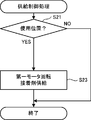
図13を参照し、供給制御処理について説明する。供給制御処理では、支持部16の位置が使用位置となっている場合にのみ、ノズル17からの接着剤の吐出を許可する。支持部16の位置が保守位置となっている場合には、ノズル17から接着剤を吐出させない。これにより、加熱させた接着剤がユーザに掛って危害を及ぼしてしまうことを防止する。
The supply control process will be described with reference to FIG. In the supply control process, the discharge of the adhesive from the
図13に示すように、ユーザがペダル208を踏み込んだことを検出して供給制御処理を開始した場合、はじめに、CPU201は、検出するエアシリンダ24のピストンの稼働位置を位置センサ222によって認識し、エアシリンダ24の伸縮状態を確認する。エアシリンダ24が伸長している場合、CPU201は支持部16を使用位置に配置させた状態であると判断する(S21:YES)。この場合、ノズル17の吐き出し口86より接着剤を吐出させてもユーザに危害を及ぼしてしまう危険性はない。そこでCPU201は、第一モータ91を回転させてギアポンプ124を回動させ、ノズル17に接着剤を供給させる。そして吐き出し口86より接着剤を吐出させる(S23)。そして供給制御処理を終了する。これにより、布に接着剤を付着させて布同士を接着させる布接着作業を実行する。
As shown in FIG. 13, when the supply control process is started by detecting that the user has stepped on the
一方、エアシリンダ24が縮んでいる場合、CPU201は支持部16を保守位置に配置させた状態であると判断する(S21:NO)。この場合には、ユーザがノズル17の状態を確認する保守作業を行っている可能性があるので、加熱させた接着剤を吐き出し口86より吐出させた場合、ユーザに接着剤が掛ってしまって危害を及ぼしてしまう危険性がある。そこでCPU201は、第一モータ91の回転を禁止して接着剤をノズル17に供給させず、そのまま供給制御処理を終了する。
On the other hand, when the
以上説明したように、布接着装置1は、上移送ローラ22の移送方向上流側近傍にノズル17を配置させる。これによって、ノズル17より吐出させた接着剤が付着した状態の布を、確実に上移送ローラ22及び下移送ローラ25にて押圧し移送させることが可能となる。また、回動可能なローラからなる上移送ローラ22及び下移送ローラ25を使用しているので、接着剤が付着した状態の布を押圧しながら移送させることが可能となる。これによって、布同士を接着剤により接着することが可能となるので、縫糸で布を縫製した場合に形成される、縫糸による表面の凹凸が形成されない。従って、布表面を滑らかな状態に保持したまま布同士を接着させることが可能となる。
As described above, the
また布接着装置1では、ノズル17は支持部16の下端部44より左方向に水平に延設している。第二ポンプケース32が支持部16の上端部42を軸支しているので、支持部16の下端部44と台座部11との間に僅かな隙間を形成させる。これによって、布の接着作業時において、ノズル17が前後方向に通過する布の邪魔になってしまう不具合を防止することが可能となる。
In the
また布接着装置1では、ばね21がローラ保持部20を下方に押し下げる。従って、ローラ保持部20の前端部58の上移送ローラ22は、接着させる布の厚さの変化に応じて柔軟に位置を変化させ、布を下方に付勢する。これによって、接着させる布の厚さが変化した場合における上移送ローラ22の配置調整の手間を省くことが可能となる。
In the
また布接着装置1は、布に付着させる接着剤を貯蔵するための貯蔵室18を備えているので、布の接着作業時において、逐一布接着装置1に対して外部から接着剤を供給する手間を省くことが可能となる。
Moreover, since the
また布接着装置1は、貯蔵室18に貯蔵室第一ヒータ101及び貯蔵室第二ヒータ102を備えている。貯蔵室第一ヒータ101及び貯蔵室第二ヒータ102は、貯蔵室18に蓄えられている状態の接着剤を加熱し、液体状態にする。これによって、ホットメルトタイプの接着剤を使用して布同士を接着させることが可能となる。また、予め貯蔵室18内の接着剤を加熱して液体状態に保持することによって、ユーザから接着作業の開始指示があった場合に、接着剤の加熱に余分な時間を要してしまってユーザを待機させてしまう不都合を抑制することが可能となる。
The
また布接着装置1は、上述の温度制御処理において、貯蔵室温度センサ111の温度に基づいて貯蔵室第一ヒータ101、及び貯蔵室第二ヒータ102のON/OFF制御を行うので、接着剤を液体状態に保持させるために必要な加熱のみ行い、過度な加熱を行わない。これによって、加熱に要する電力を抑制することが可能となる。
The
また布接着装置1は、ポンプケース14にギアポンプ124を備えているので、貯蔵室18より所定量の接着剤をノズル17に対して導くことが可能となる。これによって、布の材質や移送速度に応じて最適量の接着剤を布に付着させて接着作業を実行することが可能となる。
Further, since the
また布接着装置1は、接着剤を供給する為の供給路(供給路81〜84)を備えるので、貯蔵室18に蓄えられた状態の接着剤をスムーズにノズル17に対して供給し、吐き出し口86より吐き出させることが可能となる。また布接着装置1は、供給路を通流する接着剤を加熱する為のヒータ(ポンプケースヒータ103、支持部ヒータ104)を備える。これによって、貯蔵室18内にて加熱させた接着剤が供給路を通流することによって冷却され固化してしまうことを防止することが可能なる。
Moreover, since the
また布接着装置1は、上述の温度制御処理において、ポンプケースヒータ103によりポンプケース14の加熱制御を行う。また、支持部ヒータ104により支持部16の加熱制御をおこなう。これによって供給路81〜83を通流する接着剤を加熱することが可能となるので、接着剤を液体状態に維持しつつ、接着剤をノズル17に供給することが可能となる。また、ポンプ温度センサ112、及び支持部温度センサ113の温度に基づいてポンプケースヒータ103及び支持部ヒータ103のON/OFF制御を行う。これによって、接着剤を液体状態に維持するために必要な加熱のみ行い、過度な加熱を行わないようにする。従って、加熱に要する電力を抑制することが可能となる。
The
また布接着装置1は、支持部16を使用位置に移動させることによって、支持部16の下端部44より延設するノズル17を、上移送ローラ22における布移送方向上流側近傍に配置させる。一方、支持部16を保守位置に移動させることによって、ノズル17を上移送ローラ22及び台座部11から離隔した位置に配置させる。保守位置となっている状態では、吐き出し口86は前方斜め下方向を向いた状態となる。これによって、ユーザがノズル17を視認して吐き出し口86の詰まり具合を確認するような保守作業をおこなう場合において、容易にノズル17の吐き出し口86の状態を視認することが可能となる。
Further, the
また布接着装置1は、上述の供給制御処理において、支持部16を使用位置に配置させた状態となっている場合にのみ、第一モータ91を回転させてノズル17の吐き出し口86から接着剤を吐出させる。これにより、接着剤を布に付着させて布同士を接着させる布接着作業が実行可能となる。一方、支持部16を保守位置に配置させた状態となっている場合には、第一モータ91の回転を禁止し、ノズル17の吐き出し口86から吐出させない。支持部16を保守位置に配置させた状態となっている場合には、ユーザがノズル17の保守を行うために吐き出し口86を視認している可能性がある。このような場合に吐き出し口86より接着剤は吐出されないので、保守作業中のユーザに加熱された接着剤が掛ってしまうことがない。
The
なお、図2の上移送ローラ22及び図6の下移送ローラ25が本発明の「移送手段」に相当する。図6の貯蔵室第一ヒータ101、貯蔵室第二ヒータ102、ポンプケースヒータ103、及び支持部ヒータ104が本発明の「加熱手段」に相当する。図12のS15及びS17の処理を行うCPU201が本発明の「温度制御手段」に相当する。図11の位置センサ222が本発明の「位置検出手段」に相当する。図6のギアポンプ124が本発明の「供給手段」に相当する。図13において、支持部16の稼働位置に基づいて第一モータ91の回転を制御し、ギアポンプ124の回動を制御する処理を行うCPU201が本発明の「供給制御手段」に相当する。
The
なお、本発明は上記実施の形態に限定されるものではなく、種々の変更が可能である。上記実施の形態では、支持部16の稼働位置に基づいて接着剤の吐出の可否を決定していたが、本発明はこの構成に限定されない。以下、本発明の変形例について説明する。
In addition, this invention is not limited to the said embodiment, A various change is possible. In the embodiment described above, whether or not the adhesive can be discharged is determined based on the operating position of the
図14を参照し、本発明の変形例における供給制御処理について説明する。図14は、本発明の変形例における供給制御処理を示すフローチャートである。CPU201は、布の接着作業が可能な状態で、ユーザがペダル208を踏み込んだことを検出した場合に、変形例における供給制御処理を実行する。なお、上述の供給制御処理と同一処理部分については、説明を省略し又は簡略している。
With reference to FIG. 14, the supply control process in the modification of this invention is demonstrated. FIG. 14 is a flowchart showing a supply control process in a modification of the present invention. When the
変形例における供給制御処理では、ユーザはパネルキー209の一つである供給スイッチのON/OFFを制御することにより、ノズル17の吐き出し口86からの接着剤の吐出の許否を予め設定する。そして、支持部16を保守位置に配置させている状態であっても、供給スイッチがONされている場合には、ノズル17からの接着剤の吐出を許可する。これにより、支持部16を保守位置とした状態で、ノズル17より強制的に接着剤を吐出させる保守動作(パージ動作)を実行させることが可能となっている。
In the supply control process in the modification, the user presets whether or not to discharge the adhesive from the
図14に示すように、ユーザがペダル208を踏み込んだことを検出して供給制御処理を開始した場合、はじめに、CPU201は、位置センサ222にて検出するエアシリンダ24のピストンの稼働位置を認識し、エアシリンダ24の伸縮状態を確認する。エアシリンダ24が伸長している場合、CPU201は支持部16を使用位置に配置させた状態であると判断し(S31:YES)第一モータ91を回転させてギアポンプ124を回動させ、ノズル17に接着剤を供給させる。そして吐き出し口86より接着剤を吐出させる(S35)。そして供給制御処理を終了する。これにより、布に接着剤を付着させて布同士を接着させる布接着作業を実行する。
As shown in FIG. 14, when the supply control process is started by detecting that the user depresses the
一方、エアシリンダ24が縮んでいる場合、CPU201は支持部16を保守位置に配置させた状態であると判断する(S31:NO)。この場合CPU201は、供給スイッチがONしているかどうかを判断する(S33)。供給スイッチがONしている場合には(S33:YES)、第一モータ91を回転させてギアポンプ124を回動させ、ノズル17に接着剤を供給させる。そして吐き出し口86より接着剤を吐出させる(S35)。そして供給制御処理を終了する。一方、供給スイッチがOFFしている場合には(S33:NO)、CPU201は、第一モータ91の回転を禁止して接着剤をノズル17に供給させず、そのまま供給制御処理を終了する。
On the other hand, when the
以上のように、変形例における供給制御処理では、支持部16を保守位置に配置させた状態であっても、供給スイッチがONしている場合には、第一モータ91を回転させてノズル17の吐き出し口86から接着剤を吐出させる。これにより、支持部16を保守位置に配置させた状態で、接着剤の通流を確保するために接着剤を強制排出させるパージ動作を実行することが可能となる。
As described above, in the supply control process in the modified example, even when the
なお、図11のパネルキー209の一つである供給スイッチが、本発明の「許可手段」に相当する。
A supply switch that is one of the
なお、本発明は上記実施の形態及び変形例に限定されるものではなく、種々の変更が可能である。上述の実施の形態では、接着機2の支持部16は上下方向を長手方向とするように位置し、上端部42にて軸支されていたが、本発明はこの構成に限定されない。従って例えば、支持部16は左右方向を長手方向とするように位置し、脚注部12より軸支される構成であってもよい。
In addition, this invention is not limited to the said embodiment and modification, A various change is possible. In the above-described embodiment, the
上述の実施の形態では、支持部16は、エアシリンダ24の伸縮によって移動し、ノズル17を上下方向に揺動させることが可能であった。しかしながら本発明はこの構成に限定されない。従って例えば、支持部16は、ノズル17を前方水平方向に移動させることが可能な構成であってもよい。ノズル17の下方に接着機2の台座部11が位置しない状態まで、ノズル17を前方に移動させることによって、ユーザはノズル17を視認する保守作業を容易に行うことが可能となる。
In the above-described embodiment, the
上述の実施の形態では、ギアポンプ124が所定量の接着剤をノズル17に供給していたが、接着剤の供給を制御する手段はギアポンプ124に限定されない。従って例えば、供給路に設けられたバルブの開閉によって接着剤の供給を制御してもよいし、エアの圧力によって供給路に接着剤を強制的に通流させ、接着剤を供給してもよい。
In the above embodiment, the
1 布接着装置
2 接着機
16 支持部
17 ノズル
18 貯蔵室
20 ローラ保持部
22 上移送ローラ
24 エアシリンダ
25 下移送ローラ
81、82、83、84 供給路
91 第一モータ
92 第二モータ
93 第三モータ
101 貯蔵室第一ヒータ
102 貯蔵室第二ヒータ
103 ポンプケースヒータ
104 支持部ヒータ
111 貯蔵室温度センサ
112 ポンプ温度センサ
113 支持部温度センサ
122 ポンプギア
123 ポンプギア
124 ギアポンプ
201 CPU
209 パネルキー
210 操作パネル
222 位置センサ
DESCRIPTION OF
209 Panel key 210
Claims (9)
前記接着剤が吐き出された前記布を押圧して移送する移送手段と、
前記ノズルに前記接着剤を供給する供給路と、
前記供給路を所定温度に加熱する加熱手段と、
前記加熱手段による加熱温度を制御する温度制御手段と、
前記供給路に供給する前記接着剤を蓄える貯蔵室と
を備え、
前記ノズルは、前記移送手段の近傍であり、前記布が前記移送手段により移送される移送方向の上流側に配置され、前記供給路を備えた支持部より延設され、
前記吐き出し口は、前記対向配置される布にて挟まれる部分に配置され、
前記加熱手段は、ヒータにより構成され、前記供給路、及び前記貯蔵室を所定温度に加熱することを特徴とする布接着装置。 A nozzle having a spout for spitting out the adhesive between the cloths arranged opposite to each other;
Transfer means for pressing and transferring the cloth from which the adhesive has been discharged;
A supply path for supplying the adhesive to the nozzle;
Heating means for heating the supply path to a predetermined temperature;
Temperature control means for controlling the heating temperature by the heating means ;
A storage chamber for storing the adhesive to be supplied to the supply path ;
The nozzle is in the vicinity of the transfer means, and is disposed on the upstream side in the transfer direction in which the cloth is transferred by the transfer means, and is extended from a support portion including the supply path,
The discharge port is disposed in a portion sandwiched between the opposed fabrics,
The cloth bonding apparatus characterized in that the heating means includes a heater and heats the supply path and the storage chamber to a predetermined temperature .
前記温度制御手段は、
前記温度センサにより検出された前記温度に基づき、前記加熱手段による加熱温度を制御することを特徴とする請求項1に記載の布接着装置。 A temperature sensor capable of detecting the temperature of the adhesive;
The temperature control means includes
Wherein on the basis of the detected temperature by the temperature sensor, the cloth bonding apparatus according to claim 1, characterized in that for controlling the heating temperature by the heating means.
前記供給手段を駆動制御する供給制御手段とを備え、
前記供給制御手段は、
前記ノズルが前記保守位置に配置されていることを前記位置検出手段が検出したときには、前記供給手段による前記接着剤の供給動作を停止させ、
前記ノズルが前記使用位置に配置されていることを前記位置検出手段が検出したときには、前記供給手段による前記接着剤の供給を許可することを特徴とする請求項6に記載の布接着装置。 Supply means for supplying a predetermined amount of the adhesive to the supply path;
Supply control means for driving and controlling the supply means,
The supply control means includes
When the position detection means detects that the nozzle is disposed at the maintenance position, the supply operation of the adhesive by the supply means is stopped,
The cloth bonding apparatus according to claim 6 , wherein when the position detecting unit detects that the nozzle is disposed at the use position, the supply of the adhesive by the supplying unit is permitted.
前記供給制御手段は、
前記ノズルが前記保守位置に配置されていることを前記位置検出手段が検出した場合であって、前記許可手段にて前記接着剤の供給を許可している場合には、前記供給手段による前記接着剤の供給を許可することを特徴とする請求項8に記載の布接着装置。 Comprising permission means for permitting the supply of the adhesive by the supply means,
The supply control means includes
When the position detecting unit detects that the nozzle is disposed at the maintenance position, and when the supply of the adhesive is permitted by the permission unit, the adhesion by the supply unit The cloth bonding apparatus according to claim 8 , wherein supply of the agent is permitted.
Priority Applications (3)
| Application Number | Priority Date | Filing Date | Title |
|---|---|---|---|
| JP2009023227A JP5251560B2 (en) | 2009-02-04 | 2009-02-04 | Cloth bonding equipment |
| CN2009102256149A CN101792974B (en) | 2009-02-04 | 2009-11-20 | Cloth bonding apparatus |
| EP10152045.0A EP2216162B1 (en) | 2009-02-04 | 2010-01-29 | Cloth bonding apparatus |
Applications Claiming Priority (1)
| Application Number | Priority Date | Filing Date | Title |
|---|---|---|---|
| JP2009023227A JP5251560B2 (en) | 2009-02-04 | 2009-02-04 | Cloth bonding equipment |
Publications (2)
| Publication Number | Publication Date |
|---|---|
| JP2010180486A JP2010180486A (en) | 2010-08-19 |
| JP5251560B2 true JP5251560B2 (en) | 2013-07-31 |
Family
ID=42112227
Family Applications (1)
| Application Number | Title | Priority Date | Filing Date |
|---|---|---|---|
| JP2009023227A Active JP5251560B2 (en) | 2009-02-04 | 2009-02-04 | Cloth bonding equipment |
Country Status (3)
| Country | Link |
|---|---|
| EP (1) | EP2216162B1 (en) |
| JP (1) | JP5251560B2 (en) |
| CN (1) | CN101792974B (en) |
Families Citing this family (8)
| Publication number | Priority date | Publication date | Assignee | Title |
|---|---|---|---|---|
| JP5472060B2 (en) * | 2010-11-25 | 2014-04-16 | ブラザー工業株式会社 | Cloth bonding apparatus and bonding program |
| JP5541121B2 (en) * | 2010-11-29 | 2014-07-09 | ブラザー工業株式会社 | Cloth bonding apparatus and bonding program |
| JP6194609B2 (en) * | 2013-03-28 | 2017-09-13 | ブラザー工業株式会社 | Cloth bonding equipment |
| JP6311394B2 (en) | 2014-03-28 | 2018-04-18 | ブラザー工業株式会社 | Cloth transfer mechanism and cloth bonding device |
| JP6314594B2 (en) | 2014-03-28 | 2018-04-25 | ブラザー工業株式会社 | Cloth bonding apparatus and cloth conveyance mechanism of cloth bonding apparatus |
| JP6627240B2 (en) * | 2015-03-31 | 2020-01-08 | ブラザー工業株式会社 | Bonding apparatus and method of controlling bonding apparatus |
| JP6686288B2 (en) * | 2015-03-31 | 2020-04-22 | ブラザー工業株式会社 | Adhesive device |
| JP6686289B2 (en) * | 2015-03-31 | 2020-04-22 | ブラザー工業株式会社 | Cloth bonding apparatus and method for controlling cloth bonding apparatus |
Family Cites Families (9)
| Publication number | Priority date | Publication date | Assignee | Title |
|---|---|---|---|---|
| US2142733A (en) * | 1938-03-01 | 1939-01-03 | Movsesian Edgar | Adhesive-applying attachment for sewing machines |
| US2664938A (en) * | 1952-11-29 | 1954-01-05 | Phillips Screw Co | Plastic bonding machine |
| CH623352A5 (en) * | 1976-08-02 | 1981-05-29 | Nordson Corp | Process for bonding two substrates together with the aid of a heat-activated thermoplastic adhesive and apparatus for making use of this process |
| US4602975A (en) * | 1984-02-23 | 1986-07-29 | Paper-Pak Products, Inc. | Adhesive strip applicator method and apparatus |
| JPH0770807A (en) * | 1993-08-31 | 1995-03-14 | Hiromichi Shimizu | Sewing method using adhesive and sewing machine |
| FR2737954B1 (en) * | 1995-08-24 | 1998-01-23 | Michel Bordage | METHOD AND DEVICE FOR ASSEMBLING TWO PIECES OF ETOFFE OR THE LIKE, AND ARTICLE, IN PARTICULAR CLOTHING, THUS OBTAINED |
| GB9805176D0 (en) * | 1998-03-12 | 1998-05-06 | Rosslyn Precision Ltd | Ultrasonic seam bonding method and apparatus |
| DE50103890D1 (en) * | 2000-05-24 | 2004-11-04 | Schaepper Engineering Gmbh Buc | CONNECTING TEXTILES |
| FR2869042B1 (en) * | 2004-04-20 | 2008-07-18 | Ferrari S Tissage & Enduct Sa | BONDING INTERMEDIARY, METHOD AND MACHINE FOR BONDING COATED TEXTILE SHEETS |
-
2009
- 2009-02-04 JP JP2009023227A patent/JP5251560B2/en active Active
- 2009-11-20 CN CN2009102256149A patent/CN101792974B/en active Active
-
2010
- 2010-01-29 EP EP10152045.0A patent/EP2216162B1/en not_active Not-in-force
Also Published As
| Publication number | Publication date |
|---|---|
| EP2216162A1 (en) | 2010-08-11 |
| CN101792974A (en) | 2010-08-04 |
| EP2216162B1 (en) | 2015-07-08 |
| JP2010180486A (en) | 2010-08-19 |
| CN101792974B (en) | 2012-07-25 |
Similar Documents
| Publication | Publication Date | Title |
|---|---|---|
| JP5251560B2 (en) | Cloth bonding equipment | |
| JP5310043B2 (en) | Cloth bonding equipment | |
| JP5251561B2 (en) | Cloth bonding apparatus and bonding program | |
| JP6264999B2 (en) | Cloth bonding equipment | |
| JP5218457B2 (en) | Cloth bonding equipment | |
| JP5434271B2 (en) | Cloth bonding equipment | |
| JP5177046B2 (en) | Cloth bonding equipment | |
| EP2233278B1 (en) | Cloth bonding apparatus | |
| JP6394186B2 (en) | Cloth bonding equipment | |
| JP5434270B2 (en) | Cloth bonding equipment | |
| CN106000769B (en) | The control method of adhering device and adhering device | |
| EP3749508A1 (en) | Attachment for sealing seams | |
| EP2233277B1 (en) | Cloth bonding apparatus | |
| EP2255955B1 (en) | Cloth bonding apparatus | |
| CN108116929B (en) | Bonding apparatus and method for controlling bonding apparatus | |
| JP5321485B2 (en) | Cloth bonding equipment | |
| JP5505006B2 (en) | Cloth bonding apparatus and cartridge removal method |
Legal Events
| Date | Code | Title | Description |
|---|---|---|---|
| A621 | Written request for application examination |
Free format text: JAPANESE INTERMEDIATE CODE: A621 Effective date: 20110324 |
|
| A977 | Report on retrieval |
Free format text: JAPANESE INTERMEDIATE CODE: A971007 Effective date: 20121217 |
|
| A131 | Notification of reasons for refusal |
Free format text: JAPANESE INTERMEDIATE CODE: A131 Effective date: 20121225 |
|
| A521 | Written amendment |
Free format text: JAPANESE INTERMEDIATE CODE: A523 Effective date: 20130222 |
|
| TRDD | Decision of grant or rejection written | ||
| A01 | Written decision to grant a patent or to grant a registration (utility model) |
Free format text: JAPANESE INTERMEDIATE CODE: A01 Effective date: 20130319 |
|
| A61 | First payment of annual fees (during grant procedure) |
Free format text: JAPANESE INTERMEDIATE CODE: A61 Effective date: 20130401 |
|
| R150 | Certificate of patent or registration of utility model |
Ref document number: 5251560 Country of ref document: JP Free format text: JAPANESE INTERMEDIATE CODE: R150 Free format text: JAPANESE INTERMEDIATE CODE: R150 |
|
| FPAY | Renewal fee payment (event date is renewal date of database) |
Free format text: PAYMENT UNTIL: 20160426 Year of fee payment: 3 |