JP5246860B2 - Rapid heat treatment apparatus and nozzle for rapid heat treatment apparatus - Google Patents
Rapid heat treatment apparatus and nozzle for rapid heat treatment apparatus Download PDFInfo
- Publication number
- JP5246860B2 JP5246860B2 JP2008250856A JP2008250856A JP5246860B2 JP 5246860 B2 JP5246860 B2 JP 5246860B2 JP 2008250856 A JP2008250856 A JP 2008250856A JP 2008250856 A JP2008250856 A JP 2008250856A JP 5246860 B2 JP5246860 B2 JP 5246860B2
- Authority
- JP
- Japan
- Prior art keywords
- heat treatment
- treatment gas
- nozzle
- gas injection
- injection nozzle
- Prior art date
- Legal status (The legal status is an assumption and is not a legal conclusion. Google has not performed a legal analysis and makes no representation as to the accuracy of the status listed.)
- Active
Links
- 238000010438 heat treatment Methods 0.000 title claims description 164
- 238000002347 injection Methods 0.000 claims description 71
- 239000007924 injection Substances 0.000 claims description 71
- 238000012545 processing Methods 0.000 claims description 50
- 230000007246 mechanism Effects 0.000 claims description 36
- 238000004140 cleaning Methods 0.000 claims description 22
- 239000007788 liquid Substances 0.000 claims description 5
- 239000007921 spray Substances 0.000 claims description 3
- 235000013305 food Nutrition 0.000 description 37
- 238000001816 cooling Methods 0.000 description 33
- 238000009826 distribution Methods 0.000 description 14
- 230000000694 effects Effects 0.000 description 9
- 238000012423 maintenance Methods 0.000 description 8
- 238000009434 installation Methods 0.000 description 7
- 238000005057 refrigeration Methods 0.000 description 6
- 238000007710 freezing Methods 0.000 description 4
- 230000008014 freezing Effects 0.000 description 4
- 230000001174 ascending effect Effects 0.000 description 3
- 238000000034 method Methods 0.000 description 3
- 238000005507 spraying Methods 0.000 description 3
- 238000012546 transfer Methods 0.000 description 3
- 230000009471 action Effects 0.000 description 2
- 238000013459 approach Methods 0.000 description 2
- 238000011161 development Methods 0.000 description 2
- 238000004519 manufacturing process Methods 0.000 description 2
- 239000000463 material Substances 0.000 description 2
- 230000035699 permeability Effects 0.000 description 2
- 240000007594 Oryza sativa Species 0.000 description 1
- 235000007164 Oryza sativa Nutrition 0.000 description 1
- 241000135309 Processus Species 0.000 description 1
- 238000007664 blowing Methods 0.000 description 1
- 238000004891 communication Methods 0.000 description 1
- 230000008878 coupling Effects 0.000 description 1
- 238000010168 coupling process Methods 0.000 description 1
- 238000005859 coupling reaction Methods 0.000 description 1
- 238000003780 insertion Methods 0.000 description 1
- 230000037431 insertion Effects 0.000 description 1
- 238000005304 joining Methods 0.000 description 1
- 239000012528 membrane Substances 0.000 description 1
- 239000011148 porous material Substances 0.000 description 1
- 230000008569 process Effects 0.000 description 1
- 235000009566 rice Nutrition 0.000 description 1
- 230000035939 shock Effects 0.000 description 1
- 125000006850 spacer group Chemical group 0.000 description 1
- 238000007669 thermal treatment Methods 0.000 description 1
- 238000005406 washing Methods 0.000 description 1
Images


Classifications
-
- Y—GENERAL TAGGING OF NEW TECHNOLOGICAL DEVELOPMENTS; GENERAL TAGGING OF CROSS-SECTIONAL TECHNOLOGIES SPANNING OVER SEVERAL SECTIONS OF THE IPC; TECHNICAL SUBJECTS COVERED BY FORMER USPC CROSS-REFERENCE ART COLLECTIONS [XRACs] AND DIGESTS
- Y02—TECHNOLOGIES OR APPLICATIONS FOR MITIGATION OR ADAPTATION AGAINST CLIMATE CHANGE
- Y02P—CLIMATE CHANGE MITIGATION TECHNOLOGIES IN THE PRODUCTION OR PROCESSING OF GOODS
- Y02P60/00—Technologies relating to agriculture, livestock or agroalimentary industries
- Y02P60/80—Food processing, e.g. use of renewable energies or variable speed drives in handling, conveying or stacking
Description
本発明は、搬送ベルト上に載置した食品に対して冷風、温風、熱風等の熱処理ガスを吹き付けて熱処理を行う食品搬送熱処理装置及び該装置に用いられる中空筒状の熱処理用噴射ノズルに関する。 The present invention relates to a food conveyance heat treatment apparatus for performing heat treatment by blowing a heat treatment gas such as cold air, hot air, hot air, etc. on food placed on a conveyance belt, and a hollow cylindrical heat treatment spray nozzle used in the apparatus. .
従来、搬送ベルト上に載置した食品を熱処理するための冷却装置及び加熱装置において、加熱又は冷却された気体の噴流を食品に当て、該衝突噴流の衝撃力により該食品面の境界層を掃い退け、これによって、前記気体と食品との間の熱伝達を促進させて、冷凍、冷却又は加熱などの処理を行う食品搬送熱処理装置が存在している。 2. Description of the Related Art Conventionally, in a cooling device and a heating device for heat-treating food placed on a conveyor belt, a heated or cooled gas jet is applied to the food and the boundary layer of the food surface is swept by the impact force of the collision jet Retreating, there is a food transfer heat treatment device that promotes heat transfer between the gas and the food and performs processing such as freezing, cooling or heating.
例えば、特許文献1(特公平3−52969号公報)の食品搬送処理装置には、庫体内に食品を搬送支持するための手段と、プレナム(圧力室)と連結された複数のダクト手段とを備え、該ダクト手段に設けられたノズルを通して該搬送支持手段上の食品に気体の噴流を垂直に当てるように差し向けられた冷凍等の熱処理を施すものが開示されている。
上記ダクト手段はプレナムから遠ざかる方向(搬送方向と直角方向)に横断面が次第に小さくなっており、薄板で構成されたプレナムに取り付けられて支持される構造となっている。
For example, the food conveyance processing apparatus disclosed in Patent Document 1 (Japanese Patent Publication No. 3-52969) includes means for conveying and supporting food in the container, and a plurality of duct means connected to a plenum (pressure chamber). And a heat treatment such as freezing that is directed so as to vertically apply a gas jet to the food on the transport support means through a nozzle provided in the duct means.
The duct means has a structure in which the cross section gradually becomes smaller in the direction away from the plenum (perpendicular to the conveying direction) and is supported by being attached to a plenum formed of a thin plate.
また、特許文献2(実開平6−13495号公報)には、通気性を有する無端状搬送ベルトに載置した被処理物に圧力室内の冷風を該被処理物の上方から吹き付けるように設け、被処理物を冷風のジェット流ノズルからの冷風により冷凍する装置が開示されている。この装置で、圧力室の取付けフランジ部で支持連通されて設けられたジェット流ノズルは、角パイプの底壁に設けられた二条のスリット形状のノズル口を備え、このノズル口からジェット流を被処理物に吹き付けるようになっている。 Patent Document 2 (Japanese Utility Model Laid-Open No. 6-13495) is provided so that cold air in a pressure chamber is blown from above the object to be processed placed on an endless conveying belt having air permeability, An apparatus for freezing an object to be processed by cold air from a cold air jet nozzle is disclosed. In this apparatus, a jet flow nozzle provided in communication with and supported by a mounting flange portion of a pressure chamber is provided with two slit-shaped nozzle ports provided on the bottom wall of a square pipe, and the jet flow is received from the nozzle port. It sprays on the processed material.
また、特許文献3(特開平8−103232号公報)には、ネットコンベアの米飯に冷気を噴出するジェットノズルを該コンベアの上下面に対向して設けた冷却装置が開示されている。
該ジェットノズルは冷却器からフレキシブルな送気管に連通した上下動するチャンバーで支持されており、該チャンバーの上下動に伴なってジェットノズルを該コンベアに対して接離可能となっている。そのため該ジェットノズルの掃除及び該ネットコンベアの水洗などメンテナンスが容易となっている。
Patent Document 3 (Japanese Patent Laid-Open No. 8-103232) discloses a cooling device in which jet nozzles for jetting cold air to cooked rice of a net conveyor are provided opposite to the upper and lower surfaces of the conveyor.
The jet nozzle is supported by a vertically moving chamber communicating with a flexible air supply pipe from the cooler, and the jet nozzle can be brought into and out of contact with the conveyor as the chamber moves up and down. Therefore, maintenance such as cleaning of the jet nozzle and washing of the net conveyor is facilitated.
特許文献1は、ノズルが設けられたダクト手段がプレナムから遠ざかる方向に横断面が次第に小さくなっており、また、薄板で構成されたプレナムに取り付けられて支持される構造となっている。そのため加圧気体をプレナムに与える羽根車手段の振動がダクト手段に伝わり、食品を搬送支持するための手段と噴流を垂直に当てるノズルとの間の隙間がプレナムから遠ざかる方向に均一に保つことができにくくなっており、該方向に冷却ムラが生じてしまう。また、前記ダクト手段が先細り構造であるため、ダクト内部及びノズルを容易に洗浄にすることもできなかった。 Patent Document 1 has a structure in which a duct means provided with a nozzle is gradually reduced in cross-section in a direction away from a plenum, and is attached to and supported by a plenum composed of a thin plate. Therefore, the vibration of the impeller means for supplying the pressurized gas to the plenum is transmitted to the duct means, and the gap between the means for conveying and supporting the food and the nozzle for vertically applying the jet flow should be kept uniform in the direction away from the plenum. It becomes difficult to do so, and uneven cooling occurs in this direction. Further, since the duct means has a tapered structure, the inside of the duct and the nozzle cannot be easily cleaned.
特許文献2は、図11及び図12に示すように、二条のスリット形状のジェット流jを形成するノズル口100aが底壁に設けられた角パイプ状の中空ノズル100が圧力室101の取付けフランジ部102で固く支持連通された片持ち構造で取り付けられている。被処理物fを載置する通気性を有する無端状搬送ベルト103のベルト面と二条のスリット形状のジェット流ノズルの圧力室から遠ざかる方向の隙間Y1’、Y2’を均一にする、即ちY1’=Y2’とする調節機能がないために、該隙間はY1’>Y2’又はY1’<Y2’となる。
In Patent Document 2, as shown in FIGS. 11 and 12, a square pipe-shaped
そのため通気性を有する無端状搬送ベルト面上に載置された被処理物fに該ベルト面幅方向で冷却ムラが生じてしまう。また、冷風のジェット流jを形成するノズル口100aが設けられた角パイプ状の中空ノズル100の取付けをフランジ部102で行う作業スペースを十分に確保する必要があるため、該角パイプの夫々の間隔X’を小さくすることができないなど、冷却装置の自由度が制限されていた。また、該中空ノズル100の内部を容易に洗浄することもできなかった。
Therefore, unevenness in cooling occurs in the belt surface width direction on the object to be processed f placed on the endless conveyance belt surface having air permeability. Further, since it is necessary to secure a sufficient working space for mounting the square pipe-shaped
特許文献3では、ジェットノズルを支持するチャンバーの上下動に伴なってジェットノズルをネットコンベアに対して接離可能とすることによりメンテナンスを容易にできる構成が開示されているが、ネットコンベア面と一つ々々のジェットノズルの隙間をチャンバーから遠ざかる方向に均一に調節する手段については開示されていない。 Patent Document 3 discloses a configuration that facilitates maintenance by allowing the jet nozzle to be brought into and out of contact with the net conveyor as the chamber supporting the jet nozzle moves up and down. No means for uniformly adjusting the gap between each jet nozzle in the direction away from the chamber is disclosed.
このように、特許文献1乃至3は、中空ノズル軸方向の冷却ムラを解消する手段が開示されていないのみならず、ノズル口を備えた中空ノズルの組立を簡素化したり、レイアウトに自由度をもたせ、同時に洗浄容易性などメンテナンスを容易にする手段や構成についても開示されていない。 As described above, Patent Documents 1 to 3 do not disclose a means for eliminating cooling unevenness in the axial direction of the hollow nozzle, but also simplify the assembly of the hollow nozzle provided with the nozzle port and provide flexibility in layout. At the same time, no means or configuration for facilitating maintenance such as easy cleaning is disclosed.
本発明は、かかる従来技術の課題に鑑み、搬送ベルトを用い、搬送ベルト上の被処理物に熱処理ガスを吹き付けるようにした熱処理装置において、中空ノズルによる熱処理ムラをなくして、熱交換効率を高め、熱処理効果を向上させるための熱処理ガスの吹き付け手段や熱処理ガスの均一な吹き付けを実現することを目的とする。
また、食品搬送熱処理装置のレイアウトにおける中空ノズルの自由度を広げると共に、組立の簡素化を図り、かつ洗浄等のメンテナンス作業を容易にすることを目的とする。
In view of the problems of the prior art, the present invention eliminates heat treatment unevenness by a hollow nozzle and improves heat exchange efficiency in a heat treatment apparatus using a conveyer belt and spraying heat treatment gas on an object to be treated on the conveyer belt. An object of the present invention is to realize a heat treatment gas spraying means for improving the heat treatment effect and uniform heat treatment gas spraying.
It is another object of the present invention to increase the degree of freedom of the hollow nozzle in the layout of the food conveyance heat treatment apparatus, simplify the assembly, and facilitate maintenance work such as cleaning.
かかる目的を達成するため、本発明の急速熱処理装置は、
熱処理室と、該熱処理室内に導設される無端状の搬送ベルトと、該熱処理室内に配置された熱処理ガス供給ダクトと、該熱処理ガス供給ダクトに接続され該搬送ベルトの搬送方向と交差する方向に配置されて、ノズル口から該搬送ベルト上の被処理物に熱処理ガスの衝撃噴流を付加する中空筒状の熱処理ガス噴射ノズルとを備えた急速熱処理装置において、
前記熱処理ガス噴射ノズルの基部を該熱処理ガス噴射ノズルの先端部が前記搬送ベルトのベルト面に対し接近又は離隔する方向に揺動可能になるように熱処理ガス供給ダクトに取り付ける取付機構と、
該熱処理ガス噴射ノズルの先端部を該搬送ベルトに隣接配置された固定フレームに係止させると共に、該先端部と搬送ベルトのベルト面との距離を調整可能にする調整機構と、を備え、
該調整機構により熱処理ガス噴射ノズルの先端部を揺動させて熱処理ガス噴射ノズルの先端部と該ベルト面との距離を調整することにより、熱処理ガス噴射ノズルのノズル口とベルト面との距離が熱処理ガス噴射ノズルの基部から先端部まで均一になるように構成したものである。
In order to achieve such an object, the rapid thermal processing apparatus of the present invention comprises:
A heat treatment chamber, an endless conveyance belt installed in the heat treatment chamber, a heat treatment gas supply duct disposed in the heat treatment chamber, and a direction connected to the heat treatment gas supply duct and intersecting the conveyance direction of the conveyance belt In a rapid thermal processing apparatus provided with a hollow cylindrical heat treatment gas injection nozzle that adds an impact jet of heat treatment gas to a workpiece on the conveyor belt from a nozzle port,
An attachment mechanism for attaching the base of the heat treatment gas injection nozzle to the heat treatment gas supply duct so that the tip of the heat treatment gas injection nozzle can swing in a direction approaching or separating from the belt surface of the conveyor belt;
An adjustment mechanism for locking the front end of the heat treatment gas injection nozzle to a fixed frame disposed adjacent to the transport belt and adjusting the distance between the front end and the belt surface of the transport belt;
By adjusting the distance between the front end portion of the heat treatment gas injection nozzle and the belt surface by swinging the front end portion of the heat treatment gas injection nozzle by the adjustment mechanism, the distance between the nozzle port of the heat treatment gas injection nozzle and the belt surface is reduced. The heat treatment gas injection nozzle is configured to be uniform from the base to the tip.
本発明の急速熱処理装置では、前記取付機構によって、熱処理ガス噴射ノズルの基部を熱処理ガス噴射ノズルの先端部が熱処理ガス供給ダクトに搬送ベルトのベルト面に対し接近又は離隔する方向に揺動可能になるように取り付ける。また、熱処理ガス噴射ノズルの先端部では、前記調整機構によって該先端部と搬送ベルト面との距離を調整可能にできるので、熱処理ガス噴射ノズルのノズル口と搬送ベルト面との距離を熱処理ガス噴射ノズルの基部から先端部まで均一とすることができる。
従って、搬送ベルトの搬送方向と交差する方向で熱処理ムラを解消し、熱交換効率を高め、熱処理効果を向上させることができる。そのため、搬送ベルトの設置面積を縮小し、熱処理装置を小型化できると共に、熱処理ガス量を節減できる。
In the rapid thermal processing apparatus of the present invention, the mounting mechanism can swing the base of the thermal processing gas injection nozzle in a direction in which the tip of the thermal processing gas injection nozzle approaches or separates from the belt surface of the conveyor belt to the thermal processing gas supply duct. Attach as shown. In addition, the distance between the tip of the heat treatment gas injection nozzle and the conveyor belt surface can be adjusted by the adjusting mechanism, so that the distance between the nozzle port of the heat treatment gas injection nozzle and the conveyor belt surface can be adjusted by the heat treatment gas injection. It can be made uniform from the base to the tip of the nozzle.
Therefore, it is possible to eliminate unevenness in heat treatment in the direction intersecting with the conveyance direction of the conveyance belt, increase the heat exchange efficiency, and improve the heat treatment effect. Therefore, the installation area of the conveyor belt can be reduced, the heat treatment apparatus can be downsized, and the amount of heat treatment gas can be saved.
本発明の急速熱処理装置において、前記取付機構が、前記熱処理ガス供給ダクトに設けられ熱処理ガス噴射ノズルの基部が挿入可能な大きさの熱処理ガス供給口と、熱処理ガス噴射ノズルの基部端の上辺から上方に突設された上部フランジ、該基部端の下辺から下方に突設され該上部フランジより突出幅の小さい下部フランジ、及び該下部フランジより先端部側の位置で下部フランジとの間に熱処理ガス供給口の下部縁部を挿入可能な間隔を有して下方に突設された下部突起と、からなり、上部フランジ及び下部フランジを熱処理ガス供給口内に挿入し、熱処理ガス供給口の下部縁部を下部フランジと下部突起間に位置させ、熱処理ガス噴射ノズルの自重により上部フランジを熱処理ガス供給口の上部縁部に係止させるように構成するとよい。 In the rapid thermal processing apparatus according to the present invention, the mounting mechanism is provided in the thermal processing gas supply duct and is provided with a thermal processing gas supply port having a size capable of inserting a base of the thermal processing gas injection nozzle, and an upper end of the base end of the thermal processing gas injection nozzle. An upper flange projecting upward, a lower flange projecting downward from the lower side of the base end, and having a smaller projection width than the upper flange, and a heat treatment gas between the lower flange at a position closer to the tip than the lower flange The lower edge of the supply port, and a lower protrusion projecting downward with a space capable of being inserted. The upper flange and the lower flange are inserted into the heat treatment gas supply port, and the lower edge of the heat treatment gas supply port Is located between the lower flange and the lower protrusion, and the upper flange is locked to the upper edge of the heat treatment gas supply port by the weight of the heat treatment gas injection nozzle.
かかる構成において、まず上部フランジを熱処理ガス供給口から熱処理ガス供給ダクト内に挿入する。次に、熱処理ガス噴射ノズルの基部の天井面が熱処理ガス供給口の上部縁部に接するまで上昇させて、下部フランジを熱処理ガス供給口内に差し入れる。そして、熱処理ガス供給口の下部縁部を下部フランジと下部突起間に位置させ、熱処理ガス噴射ノズルの自重により上部フランジを熱処理ガス供給口の上部縁部に係止させる。 In such a configuration, the upper flange is first inserted into the heat treatment gas supply duct from the heat treatment gas supply port. Next, the heat treatment gas injection nozzle is raised until the ceiling surface of the base portion contacts the upper edge of the heat treatment gas supply port, and the lower flange is inserted into the heat treatment gas supply port. Then, the lower edge of the heat treatment gas supply port is positioned between the lower flange and the lower protrusion, and the upper flange is locked to the upper edge of the heat treatment gas supply port by the weight of the heat treatment gas injection nozzle.
これによって、結合具を不要とする簡素な取付機構が実現できると共に、中空筒状の熱処理ガス噴射ノズルをワンタッチで熱処理ガス供給ダクトに取り付けることができるので、熱処理ガス噴射ノズルの取り付けが容易になる。
また、上部フランジ及び下部フランジによって熱処理ガス噴射ノズルが支持されるため、熱処理ガス噴射ノズルの先端部が上下に揺動可能であり、熱処理ガス噴射ノズルの先端部の高さ調節が可能になる。
As a result, a simple attachment mechanism that does not require a coupler can be realized, and a hollow cylindrical heat treatment gas injection nozzle can be attached to the heat treatment gas supply duct with one touch, so that the heat treatment gas injection nozzle can be easily attached. .
Further, since the heat treatment gas injection nozzle by the upper flange and a lower flange is supported, the distal end portion of the heat-treatment gas injection nozzle is swingable up and down, allowing height adjustment of the front end portion of the heat-treatment gas injection nozzle.
また、特許文献2のように、熱処理ガス供給ダクトの外側で搬送ベルトの搬送方向に向けてフランジ等が配置されないので、該ノズルの構成を簡素化できると共に、ノズル口配置の自由度が広がり、そのため、熱処理ガス噴射ノズル間の間隔を狭くできる。
従って、熱処理ガス噴射ノズルの配置の自由度と熱処理作用の自由度を広げることができるため、熱処理作用を受ける搬送ベルト面の設置面積を縮小し、熱処理装置を小型化できると共に、熱処理ガス量を節減できる。
Further, as in Patent Document 2, since a flange or the like is not disposed outside the heat treatment gas supply duct toward the conveyance direction of the conveyance belt, the configuration of the nozzle can be simplified, and the degree of freedom of nozzle opening is widened. Therefore, the interval between the heat treatment gas injection nozzles can be narrowed.
Accordingly, since the degree of freedom of the arrangement of the heat treatment gas injection nozzle and the degree of freedom of the heat treatment action can be expanded, the installation area of the conveyor belt surface subjected to the heat treatment action can be reduced, the heat treatment apparatus can be downsized, and the amount of heat treatment gas can be reduced. You can save.
また、本発明の急速熱処理装置において、前記調整機構が、熱処理ガス噴射ノズルの先端部に設けられたネジ孔と、該ネジ孔に螺合する雄ネジ部、及び前記搬送ベルトに隣接配置された固定フレームに係止するフックを備えた固定部材と、からなり、該雄ネジ部とネジ孔とを螺合しかつ該フックを該固定フレームに係止することにより熱処理ガス噴射ノズルの先端部を固定すると共に、該雄ネジ部とネジ孔の螺入度を調整することにより、熱処理ガス噴射ノズル先端部と搬送ベルトのベルト面との距離を調整可能に構成するとよい。 Further, in the rapid thermal processing apparatus of the present invention, the adjustment mechanism is disposed adjacent to a screw hole provided at a tip portion of the thermal treatment gas injection nozzle, a male screw portion screwed into the screw hole, and the conveyor belt. A fixing member having a hook for locking to the fixing frame, and screwing the male screw portion and the screw hole and locking the hook to the fixing frame to thereby fix the tip of the heat treatment gas injection nozzle. It is preferable that the distance between the front end portion of the heat treatment gas injection nozzle and the belt surface of the conveyance belt can be adjusted by fixing and adjusting the screwing degree of the male screw portion and the screw hole.
かかる構成とすることにより、搬送ベルトに隣接配置された固定フレームを利用した簡素な構成の調整機構を実現できる。しかも、該調整機構により、熱処理ガス噴射ノズルの先端部と搬送ベルト面との距離を調整できるので、熱処理ガス噴射ノズルのノズル口と搬送ベルト面との距離を熱処理ガス噴射ノズルの基部から先端部まで均一とすることができる。従って、搬送ベルト面の幅方向での熱処理ムラを無くし、熱処理効果を向上できる。 By adopting such a configuration, an adjustment mechanism having a simple configuration using a fixed frame disposed adjacent to the conveyance belt can be realized. Moreover, since the distance between the tip of the heat treatment gas injection nozzle and the conveyor belt surface can be adjusted by the adjusting mechanism, the distance between the nozzle port of the heat treatment gas injection nozzle and the conveyor belt surface can be adjusted from the base of the heat treatment gas injection nozzle to the tip portion. Can be uniform. Therefore, heat treatment unevenness in the width direction of the conveyor belt surface can be eliminated, and the heat treatment effect can be improved.
また、本発明の急速熱処理装置において、熱処理ガス噴射ノズルの先端部に洗浄液を該熱処理ガス噴射ノズル内に供給可能な開口を設けると共に、該洗浄用開口を遮蔽する遮蔽板を着脱可能に設けるとよい。
これによって、装置の稼動時は、該洗浄用開口を遮蔽しているので、熱処理ガスが洗浄用開口から漏れることがないので、被処理物に噴射する熱処理ガス噴射量を低減させる虞がない。そして、メンテナンス作業時には、該遮蔽板を取り外して、該洗浄用開口から洗浄液を熱処理ガス噴射ノズル内に供給できるので、洗浄作業が容易になる。
Further, in the rapid thermal processing apparatus of the present invention, an opening is provided at the tip of the thermal processing gas injection nozzle so that the cleaning liquid can be supplied into the thermal processing gas injection nozzle, and a shielding plate that shields the cleaning opening is provided detachably. Good.
Thus, when the apparatus is in operation, the cleaning opening is shielded, so that the heat treatment gas does not leak from the cleaning opening, and there is no possibility of reducing the amount of heat treatment gas sprayed onto the workpiece. In the maintenance operation, the shielding plate can be removed, and the cleaning liquid can be supplied into the heat treatment gas injection nozzle from the cleaning opening, which facilitates the cleaning operation.
本発明の急速熱処理装置では、複数の急速熱処理装置用ノズルが搬送ベルトの搬送方向に沿って密に配置できる。そして、熱処理ガス噴射ノズルのノズル口から下方に配置された搬送ベルトのベルト面に向かって該搬送ベルトの近傍から熱処理ガスを噴出し、熱処理ガス流を食品等の被処理物に衝突させる。熱処理ガス流は、搬送ベルト面に密に吹き付けられ、搬送ベルト面の幅方向に均一に食品等の被処理物の表面に密着した膜流を形成する。そのため、搬送ベルト面の幅方向における熱処理ムラ等を解消できると共に、食品等の被処理物と熱処理ガスとの熱交換効率を向上させ、熱処理効果を向上できる。 In the rapid thermal processing apparatus of the present invention, a plurality of rapid thermal processing apparatus nozzles can be densely arranged along the transport direction of the transport belt. Then, the heat treatment gas is ejected from the vicinity of the conveyor belt toward the belt surface of the conveyor belt disposed below from the nozzle port of the heat treatment gas injection nozzle, and the heat treatment gas flow is made to collide with an object to be processed such as food. The heat treatment gas flow is densely sprayed on the surface of the transport belt, and forms a film flow that is in close contact with the surface of an object to be processed such as food in the width direction of the transport belt surface. Therefore, unevenness in heat treatment in the width direction of the conveyor belt surface can be eliminated, and the heat exchange efficiency between the object to be processed such as food and the heat treatment gas can be improved, and the heat treatment effect can be improved.
また、急速熱処理装置用ノズルの熱処理ガス供給ダクトへの装着が容易になると共に、中空ノズルの組立及び洗浄等のためのスペースを大きくとる必要がなくなり、そのため、レイアウトの自由度が広がり、組立時の精度も緩やかとなり、組立も容易となる。同時に熱処理ガスと被処理物の熱交換効率を向上させることができるので、食品の熱処理速度を増加させることができる。従って、食品等の被処理物の熱処理室内における搬送経路を短くできるので、熱処理装置の据付面積を縮小できる。 In addition, the rapid thermal processing apparatus nozzle can be easily mounted on the heat treatment gas supply duct, and it is not necessary to take a large space for assembly and cleaning of the hollow nozzle. The accuracy of this is also reduced, and assembly is facilitated. At the same time, since the heat exchange efficiency between the heat treatment gas and the object to be treated can be improved, the heat treatment speed of the food can be increased. Therefore, since the conveyance path | route in the heat processing chamber of to-be-processed objects, such as a foodstuff, can be shortened, the installation area of a heat processing apparatus can be reduced.
また、本発明の中空形状の急速熱処理装置用ノズルは、前記本発明の急速熱処理装置に用いられるものであり、
ノズル本体の基部をノズル本体の先端部が前記搬送ベルトに対し接近又は離隔する方向に揺動可能になるように熱処理ガス供給ダクトに取り付ける取付機構と、
ノズル本体の先端部を該搬送ベルトに隣接配置された固定フレームに係止させると共に、該先端部と搬送ベルト面との距離を調整可能にする調整機構とを備え、
該調整機構によりノズル本体の先端部を揺動させて該先端部と搬送ベルト面との距離を調整することにより、ノズル口と搬送ベルト面との距離を基部から先端部まで均一とするように構成したものである。
Moreover, the hollow-shaped rapid thermal processing apparatus nozzle of the present invention is used for the rapid thermal processing apparatus of the present invention,
An attachment mechanism for attaching the base of the nozzle body to the heat treatment gas supply duct so that the tip of the nozzle body can swing in a direction approaching or separating from the conveyor belt;
The front end of the nozzle body is locked to a fixed frame disposed adjacent to the transport belt, and an adjustment mechanism that enables the distance between the front end and the transport belt surface to be adjusted,
By swinging the tip of the nozzle body with the adjusting mechanism and adjusting the distance between the tip and the conveyor belt surface, the distance between the nozzle opening and the conveyor belt surface is made uniform from the base to the tip. It is composed.
本発明の急速熱処理装置用ノズルにおいて、前記取付機構が、前記熱処理ガス供給ダクトに設けられノズル本体の基部が挿入可能な大きさの熱処理ガス供給口と、ノズル本体の基部端の上辺から上方に突設された上部フランジ、該基部端の下辺から下方に突設され該上部フランジより突出幅の小さい下部フランジ、及び該下部フランジより先端部側の位置で下部フランジとの間に熱処理ガス供給口の下部縁部を挿入可能な間隔を有して下方に突設された下部突起と、からなり、上部フランジ及び下部フランジを熱処理ガス供給口内に挿入し、熱処理ガス供給口の下部縁部を下部フランジと下部突起間に位置させ、熱処理ガス噴射ノズルの自重により上部フランジを熱処理ガス供給口の上部縁部に係止させるように構成するとよい。 In the nozzle for rapid thermal processing apparatus according to the present invention, the mounting mechanism is provided in the thermal processing gas supply duct and is provided with a thermal processing gas supply port having a size capable of inserting a base portion of the nozzle body, and upward from the upper side of the base end of the nozzle body. A projecting upper flange, a lower flange projecting downward from the lower side of the base end and having a smaller projecting width than the upper flange, and a heat treatment gas supply port between the lower flange at a position closer to the tip than the lower flange The lower edge of the heat treatment gas supply port is inserted into the heat treatment gas supply port, and the lower edge of the heat treatment gas supply port is formed in the lower part. It is good to comprise between a flange and a lower processus | protrusion, and a top flange is latched by the upper edge of a heat processing gas supply port with the dead weight of a heat processing gas injection nozzle.
かかる構成とすることによって、前述のように、結合具を不要とする簡素な取付機構が実現できると共に、中空筒状の熱処理ガス噴射ノズルをワンタッチで熱処理ガス供給ダクトに取り付けることができるので、熱処理ガス噴射ノズルの取り付けが容易になる。
また、上部フランジ及び下部フランジによって熱処理ガス噴射ノズルが支持されるため、熱処理ガス噴射ノズルの先端部が上下に揺動可能であり、熱処理ガス噴射ノズルの先端部の高さ調節が可能になる。
By adopting such a configuration, as described above, a simple attachment mechanism that does not require a coupler can be realized, and a hollow cylindrical heat treatment gas injection nozzle can be attached to the heat treatment gas supply duct with one touch. Installation of the gas injection nozzle becomes easy.
Further, since the heat treatment gas injection nozzle by the upper flange and a lower flange is supported, the distal end portion of the heat-treatment gas injection nozzle is swingable up and down, allowing height adjustment of the front end portion of the heat-treatment gas injection nozzle.
また、本発明の急速熱処理装置用ノズルにおいて、前記調整機構が、ノズル本体の先端部に設けられたネジ孔と、該ネジ孔に螺合する雄ネジ部、及び前記搬送ベルトに隣接配置された固定フレームに係止するフックを備えた固定部材と、からなり、該雄ネジ部とネジ孔とを螺合しかつ該フックを該固定フレームに係止することにより該先端部を固定すると共に、該雄ネジ部とネジ孔の螺入度を調整することにより、該先端部と搬送ベルトのベルト面との距離を調整可能に構成するとよい。 Further, in the nozzle for rapid thermal processing apparatus of the present invention, the adjustment mechanism is disposed adjacent to a screw hole provided at a tip portion of the nozzle body, a male screw portion screwed into the screw hole, and the conveyor belt. A fixing member having a hook for locking to the fixed frame, and fixing the tip by screwing the male screw portion and the screw hole and locking the hook to the fixed frame; It is preferable that the distance between the leading end portion and the belt surface of the conveyor belt can be adjusted by adjusting the screwing degree of the male screw portion and the screw hole.
かかる構成とすることによって、搬送ベルトに隣接配置された固定フレームを利用した簡素な構成の調整機構を実現できる。これによって、ノズル本体の先端部と搬送ベルト面との距離を調整できるので、ノズル口と搬送ベルト面との距離をノズル本体の基部から先端部まで均一とすることができる。従って、搬送ベルト面の幅方向での熱処理ムラを無くし、熱処理効果を向上できる。 By adopting such a configuration, an adjustment mechanism having a simple configuration using a fixed frame disposed adjacent to the conveyance belt can be realized. Thereby, since the distance between the tip of the nozzle body and the conveyor belt surface can be adjusted, the distance between the nozzle opening and the conveyor belt surface can be made uniform from the base to the tip of the nozzle body. Therefore, heat treatment unevenness in the width direction of the conveyor belt surface can be eliminated, and the heat treatment effect can be improved.
本発明の急速熱処理装置によれば、熱処理室と、該熱処理室内に導設される無端状の搬送ベルトと、該熱処理室内に配置された熱処理ガス供給ダクトと、該熱処理ガス供給ダクトに接続され該搬送ベルトの搬送方向と交差する方向に配置されて、ノズル口から該搬送ベルト上の被処理物に熱処理ガスの衝撃噴流を付加する中空筒状の熱処理ガス噴射ノズルとを備えた急速熱処理装置において、前記熱処理ガス噴射ノズルの基部を該熱処理ガス噴射ノズルの先端部が前記搬送ベルトのベルト面に対し接近又は離隔する方向に揺動可能になるように熱処理ガス供給ダクトに取り付ける取付機構と、該熱処理ガス噴射ノズルの先端部を該搬送ベルトに隣接配置された固定フレームに係止させると共に、該先端部と搬送ベルトのベルト面との距離を調整可能にする調整機構と、を備え、該調整機構により熱処理ガス噴射ノズルの先端部を揺動させて熱処理ガス噴射ノズルの先端部と該ベルト面との距離を調整することにより、該熱処理ガス噴射ノズルのノズル口とベルト面との距離が熱処理ガス噴射ノズルの基部から先端部まで均一になるように構成したので、搬送ベルト面の幅方向に均一に食品等の被処理物の表面に密着した膜流を形成することができる。 According to the rapid thermal processing apparatus of the present invention, the thermal processing chamber, an endless conveying belt led in the thermal processing chamber, a thermal processing gas supply duct disposed in the thermal processing chamber, and the thermal processing gas supply duct are connected. A rapid thermal processing apparatus provided with a hollow cylindrical heat treatment gas injection nozzle that is disposed in a direction intersecting with the conveyance direction of the conveyance belt and applies a shock jet of heat treatment gas to an object to be treated on the conveyance belt from a nozzle opening An attachment mechanism for attaching the base portion of the heat treatment gas injection nozzle to the heat treatment gas supply duct so that the tip portion of the heat treatment gas injection nozzle can swing in a direction approaching or separating from the belt surface of the transport belt; The front end of the heat treatment gas injection nozzle is locked to a fixed frame arranged adjacent to the transport belt, and the distance between the front end and the belt surface of the transport belt is adjusted. And a control mechanism that allows, by adjusting the distance between the tip and the belt surface of the heat-treatment gas injection nozzle to oscillate the tip of the heat treatment gas injection nozzle by the adjusting mechanism, the heat treatment gas injection Since the distance between the nozzle port of the nozzle and the belt surface is uniform from the base part to the tip part of the heat treatment gas injection nozzle, it is in close contact with the surface of the object to be processed such as food in the width direction of the conveying belt surface. A membrane flow can be formed.
そのため、搬送ベルト面の幅方向における冷却ムラ等を解消できると共に、食品等の被処理物と熱処理ガスとの熱交換効率を高め、熱処理効果を向上できる。そのため、被処理物の熱処理速度を増加させることができるので、被処理物の熱処理室内における搬送経路を短くでき、熱処理装置の据付面積を縮小できる。
また、簡素かつ低コストな構成の該取付機構によって、熱処理ガス噴射ノズルを熱処理ガス供給ダクトにワンタッチで容易に取り付けが可能になると共に、該調整機構によって熱処理ガス噴射ノズルの高さ調整が容易になる。
Therefore, it is possible to eliminate uneven cooling in the width direction of the conveyor belt surface, increase the heat exchange efficiency between the object to be processed such as food and the heat treatment gas, and improve the heat treatment effect. Therefore, since the heat treatment rate of the object to be treated can be increased, the transfer path of the object to be treated in the heat treatment chamber can be shortened, and the installation area of the heat treatment apparatus can be reduced.
In addition, the mounting mechanism having a simple and low-cost configuration allows the heat treatment gas injection nozzle to be easily attached to the heat treatment gas supply duct with one touch, and the adjustment mechanism makes it easy to adjust the height of the heat treatment gas injection nozzle. Become.
また、前記本発明の急速熱処理装置に適用される本発明の急速熱処理装置用ノズルによれば、ノズル本体の基部をノズル本体の先端部が前記搬送ベルトに対し接近又は離隔する方向に揺動可能になるように熱処理ガス供給ダクトに取り付ける取付機構と、ノズル本体の先端部を該搬送ベルトに隣接配置された固定フレームに係止させると共に、該先端部と搬送ベルトのベルト面との距離を調整可能にする調整機構とを備え、該調整機構によりノズル本体の先端部を揺動させて該先端部と該ベルト面との距離を調整することにより、簡素かつ低コストで、ノズル本体に設けられたノズル口とベルト面との距離がノズル本体の基部から先端部まで均一になるように構成したので、搬送ベルト面の幅方向に均一に食品等の被処理物の表面に密着した膜流を形成することができるので、搬送ベルト面の幅方向における冷却ムラ等を解消できると共に、食品等の被処理物と熱処理ガスとの熱交換効率を高め、熱処理効果を向上できる。
According to the nozzle for rapid thermal processing apparatus of the present invention applied to the rapid thermal processing apparatus of the present invention, the base of the nozzle body can be swung in the direction in which the tip of the nozzle body approaches or separates from the transport belt. The mounting mechanism attached to the heat treatment gas supply duct and the tip of the nozzle body are locked to the fixed frame adjacent to the conveyor belt, and the distance between the tip and the belt surface of the conveyor belt is adjusted. An adjustment mechanism that allows the nozzle body to swing, and the distance between the tip and the belt surface is adjusted by swinging the tip of the nozzle body. Since the distance between the nozzle port and the belt surface is uniform from the base to the tip of the nozzle body, it is in close contact with the surface of the object to be processed such as food in the width direction of the conveyor belt surface. It is possible to form a flow, it is possible to eliminate the cooling unevenness in the width direction of the conveyor belt surface, increasing the efficiency of heat exchange with an object to be processed with a heat treatment gas such as food, it can improve the heat treatment effect.
以下、本発明を図に示した実施形態を用いて詳細に説明する。但し、この実施形態に記載されている構成部品の寸法、材質、形状、その相対配置などは特に特定的な記載がない限り、この発明の範囲をそれのみに限定する趣旨ではなく、単なる説明例にすぎない。 Hereinafter, the present invention will be described in detail with reference to embodiments shown in the drawings. However, the dimensions, materials, shapes, relative arrangements, and the like of the components described in this embodiment are not intended to limit the scope of the present invention only to specific examples unless otherwise specifically described. Only.
本発明をスパイラルフリーザに適用した一実施形態を図1〜図5に基づいて説明する。図1は本実施形態に係るスパイラルフリーザの平面図、図2は図1中のA−A線に沿う横断側面図である。図1及び図2において、密閉空間を形成し得る冷凍庫10の内部に、ネットで構成され網目状の多数の細孔をもつ無端状搬送ベルト12が螺旋状に配置されている。そして、矢印a方向に搬送される搬送ベルト2上に所定間隔をもって載置された食品fに対して、0℃以下の低温空気を噴射して急速凍結する螺旋移動部14が形成されている。
An embodiment in which the present invention is applied to a spiral freezer will be described with reference to FIGS. FIG. 1 is a plan view of a spiral freezer according to the present embodiment, and FIG. 2 is a cross-sectional side view taken along line AA in FIG. In FIG. 1 and FIG. 2, an endless conveying
無端状搬送ベルト12は、その入口搬送路12aが冷凍庫10の出入口10aから冷凍庫10の内部に導設され、螺旋移動部14で螺旋状に上昇する搬送路12bを形成する。この螺旋状上昇路12bは、上端でS字カーブを形成して反転するS字状反転路12cを形成した後、該螺旋状上昇路12b間を螺旋状に下降する螺旋状下降路12dを形成する。そして、該螺旋状下降路12dの下端から入口搬送路12aの下方に配設され、出入口10aを通って冷凍庫1の外部に出る図示しない出口搬送路を形成している。
The endless conveying
螺旋状上昇路12bと螺旋状下降路12dが形成された螺旋移動部14は、中央に位置する直線部14aと両端の円弧部14bとからなり、上方から視て楕円に近い形状をなしている。螺旋移動部3を構成する無端状搬送ベルト12は、支柱16で支持され、後述する分配ダクト26や急速熱処理装置用ノズルとなる中空ノズル部30とは非接触に配置されている。
The
図2において、螺旋移動部14の中央に位置する中央直線部14aの内側には、冷凍ユニット20が配設されている。冷凍ユニット20は冷凍サイクルを構成する従来公知の冷凍機器からなり、冷凍庫10内の空気を矢印b方向から取り入れる送風機22と、取り入れた空気を0℃以下の低温に冷却する熱交換器24とを備える。熱交換器24で冷却された空気cは分配ダクト26に供給される。分配ダクト26は、冷凍ユニット20と螺旋移動部14の中央直線部14aの間に配置され、内部が中空で冷却空気cの通路を形成する。
In FIG. 2, a
分配ダクト26から外側に櫛歯状に突出した多数の筒状の中空ノズル部30が設けられている。中空ノズル部30の構成を図3〜図10に基づいて説明する。図3は図2中のB部拡大図である。図3において、中空ノズル部30は内部が中空で四角形断面を有する。中空ノズル部30は、その基部34で分配ダクト26に穿設された冷却空気供給口28と連通している。搬送ベルト12はその支持装置13に支持され、図示しない駆動装置により、支持装置13上を滑りながら矢印a方向に移動する。
A large number of cylindrical
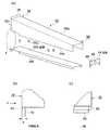
図7及び図8に示すように、中空ノズル部30は、先端部36に向うほど高さが短縮されていると共に、底壁30bの両側縁部に沿って、先端部36から基部近傍まで2条のスリット状のノズル口30dが設けられている。そして、ノズル口30dから下方に配置された搬送ベルト12の搬送面上に向けて冷却空気cが垂直に噴出するように構成されている。
As shown in FIGS. 7 and 8, the
図8(a)は中空ノズル部30の展開図である。図8(a)において、中空ノズル部30は、天井壁30a及び側壁30cからなる上部ハウジングと、底壁30cと、先端部36に設けられる盲板44とを組み合わせて構成される。側壁30cには下方に突出する突辺30eが形成されると共に、底壁30bにも下方に突出する突辺30fが形成されており、突辺30eと突辺30fとがスペーサ30gを介在させて向かい合わせに接合されることで、2条のスリット状のノズル口30dが形成される。
FIG. 8A is a development view of the
図3に示すように、中空ノズル部30の基部34は、冷却空気供給口28に支持され、中空ノズル部30の先端部36は、支柱16に水平に掛け渡された支持部材18で支持される。ノズル口30dから噴出した冷却空気cは食品fに衝突する衝突噴流となる。
図2に示すように、食品fに吹き付けられた後の冷却空気cは、分配ダクト26に設けられた図示しない戻り流路及びと循環ダクトに受け入れられ、冷凍ユニット10に戻る循環流bを形成する。
As shown in FIG. 3, the
As shown in FIG. 2, the cooling air c after being sprayed on the food f is received in a return flow path (not shown) provided in the
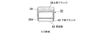
図5、6及び図8に示すように、中空ノズル部30が分配ダクト26に接続される基部34には、分配ダクト26に穿設された冷却空気供給口28に遊嵌可能な上部フランジ38、下部フランジ40及び突起板42が形成されている。これによって、後述するように、中空ノズル部30の基部34をワンタッチで分配ダクト26に接続可能となり、中空ノズル部30の取付けが容易になる。
As shown in FIGS. 5, 6, and 8, a base 34 to which the
中空ノズル部30の基部端には、天井面に上部フランジ38と、底面に下部フランジ40が設けられている。上部フランジ38と下部フランジ40の中空ノズル部30の幅方向長さは同一であり、図6に示すように、上部フランジ38の突出幅Z1は下部フランジ40の突出幅Z2より大きく構成されている。また、下部フランジ40より先端側の底面には、下部フランジ40と平行に突起板42が突設されている。
At the base end of the
図8に示すように、突起板42の突出幅は下部フランジ40の突出幅より大きく形成され、中空ノズル部30の幅方向の長さは、突起板42より下部フランジ40のほうが長く構成されている。また、下部フランジ40と突起板42間の間隔Sは、冷却空気供給口28の下部縁部26bが遊嵌可能な寸法になっている。
図4に示すように、中空ノズル部30を取り付ける側の分配ダクト26には、搬送ベルト12の搬送方向aに沿って複数の冷却空気供給口28が等間隔に穿設されている。
As shown in FIG. 8, the protruding width of the protruding
As shown in FIG. 4, a plurality of cooling
図6により、中空ノズル部30の基部34を分配ダクト26に取り付ける手順を説明する。最初に冷却空気供給口28に上部フランジ38を嵌入させ、その後、冷却空気供給口28の上部縁部26aに中空ノズル部30の天井壁30aが接するまで上昇させて、下部フランジ40を冷却空気供給口28に差し入れる。
冷却空気供給口28に下部フランジ40を挿入した後、中空ノズル部30の底壁30bを冷却空気供給口28の下部縁部26bに接するまで降下させることで接続は完了する。
The procedure for attaching the
After the
このように、冷却空気供給口28に中空ノズル部30の基部34をワンタッチで取り付けできると共に、中空ノズル部30の基部34と分配ダクト26に穿設された冷却空気供給口28との取付けは緩やかになっており、スリット状のノズル口30dの噴出方向の調節を目的として水平方向にも垂直方向にも揺動可能となっている。
As described above, the
次に、中空ノズル部30の先端部36の高さを調整可能に支持する調整機構の構成を図3、図5、図7、図9及び図10により説明する。
図7に示すように、中空ノズル部30の先端部36は、天井壁30a、底壁30b及び側壁30cと直角方向に設けられた盲板44で遮蔽されている。盲板44の中央に孔46が穿設されている。メンテナンス作業時に、孔46から洗浄液を供給することによって、中空ノズル部30を解体することなく、中空ノズル部30の内部を洗浄することが可能となっている。
Next, the configuration of an adjustment mechanism that supports the height of the
As shown in FIG. 7, the
中空ノズル部30の先端部36には、図7及び図9に示す調整装置50が装着される。調整装置50は、コ字形状の固定部材52と、固定部材52の両側部52b間に架設される横棒54と、一端にフック60を有し、他端に雄ネジ部62を有する丸棒58とからなる。固定部材52の両端側部52bには、横棒54を装着するための通し孔56が穿設されている。横棒54は、通し孔56にボルト64とワッシャ66で固定されるが、固定部材52に対して回転可能となっている。
An
横棒54の中央部には雌ネジ孔68が穿設され、雌ネジ孔68に丸棒58の雄ネジ部62が螺合している。丸棒58は、雄ネジ部62の螺入度合いに応じて横棒54との相対位置が可変となっており、矢印d方向に相対位置を移動可能になっている。また、横棒54は回動可能であるので、丸棒58が矢印e方向に回動可能になっている。丸棒58の矢印d方向位置は、ナット70で固定される。
A
固定部材52の中央部52a及び盲板44には、夫々ボルト挿通孔48が穿設され、中央部52aは盲板44に図示しない結合ボルトで接合される。これによって、盲板部44に穿設された洗浄用孔46が遮蔽されるので、本実施形態に係るスパイラルフリーザの運転中は、洗浄用孔46から低温空気cが漏れることはない。
Bolt insertion holes 48 are formed in the
かかる構成において、搬送ベルト12に隣接配置された支柱16に支持部材18が水平に掛け渡されており、フック60を支持部材18に掛けて、中空ノズル部30の先端部36を固定する。次に、ノズル口30dの噴出方向の調節を行なう。即ち、水平方向にはフック60を支持部材18に沿って水平移動させることで調節し、垂直方向にはフック60を支持部材18に掛けた状態で、丸棒58の雄ネジ部62の雌ネジ孔68に対する螺入度合いを調整する。これによって、中空ノズル部30の搬送ベルト12のベルト面に対する距離を、基部34から先端部36に亘って均一とし、かつノズル口30dを搬送ベルト12上の食品fに対して直角に向けることができる。
In such a configuration, the
かかる操作によって、搬送ベルト幅方向の冷却ムラを低減して、均一冷却が可能になる。また、ノズル口30dから噴出される低温空気cの噴流を搬送ベルト12上の食品fに向かって垂直に衝突する衝突噴流を形成することができる。これによって、食品表面の層流を破壊して、低温空気cを食品fに密着できるため、熱交換効率を高め、冷却効果を向上できる。
By such an operation, uneven cooling in the width direction of the conveyor belt is reduced, and uniform cooling is possible. Further, it is possible to form a collision jet that vertically collides the jet of the low-temperature air c ejected from the
かかる構成によって、中空ノズル部30から噴出され食品fに衝突した冷却空気cは、コアンダ効果によって食品fの表面に密着した膜流を形成し、食品fを高い熱交換効率で冷却できる。
With such a configuration, the cooling air c ejected from the
また、結合具を不要とする簡素な取付機構が実現できると共に、中空ノズル部30をワンタッチで分配ダクト26に取り付けることができるので、中空ノズル部30の取り付けが容易になる。一基のスパイラルフリーザには多数の中空ノズル部30を装着する必要がるので、中空ノズル部30の取り付けを容易にすることによって、トータルとして、大幅な製造時間及び製造コストを低減できる。
In addition, a simple attachment mechanism that does not require a coupler can be realized, and the
また、図7及び図8に示すように、中空ノズル部30の側壁30cには、フランジ等の突起部を形成する必要がなくなるため、図4に示される冷却空気供給口28同士の間隔Xは、可能な限り狭めることが可能となる。これによって、中空ノズル30の組立及び洗浄等のメンテナンススペースを大きくとる必要がなくなり、そのため、レイアウトの自由度が広がり、組立時の精度も緩やかとなり、組立も容易となる。同時に冷却空気cと被処理物である食品fの熱交換効率を向上させることができるので、食品fの熱処理速度を増加させることができる。従って、食品fの冷凍庫10内における搬送経路を短くできるので、冷凍庫10の据付面積を縮小できる。
Further, as shown in FIGS. 7 and 8, since it is not necessary to form a protrusion such as a flange on the
また、中空ノズル部30の先端部36に洗浄用孔46を設けているので、メンテナンス時に固定部材52を取り外し、洗浄用孔46から洗浄液を中空ノズル部30の内部に供給することによって、中空ノズル部30の内部を容易に洗浄できる。また、スパイラルフリーザの運転中は、固定部材52で洗浄用孔46を遮蔽しているので、食品fの冷凍処理に支障を来さない。
In addition, since the
本発明によれば、食品等の被処理物を移動する無端状搬送路で熱処理する場合に、限られた設置スペースで食品の熱処理効率を高め、さらに熱処理ガス噴射ノズルの組立を容易にし、装置のレイアウト上の自由度を広げることができる。 According to the present invention, when heat treatment is performed on an endless conveyance path for moving an object such as food, the heat treatment efficiency of the food is increased in a limited installation space, and the assembly of the heat treatment gas injection nozzle is facilitated. The degree of freedom in layout can be expanded.
10 冷凍庫
12 無端状搬送ベルト
16 支柱
18 支持部材(固定フレーム)
26 分配ダクト(熱処理ガス供給ダクト)
26a 上部縁部
26b 下部縁部
28 冷却空気供給口
30 中空ノズル部(熱処理ガス噴射ノズル)
32 ノズル口
34 基部
36 先端部
38 上部フランジ
40 下部フランジ
42 突起板
46 洗浄用孔
50 調整装置
52 固定部材(遮蔽板)
56 丸棒
60 フック
62 雄ネジ部
68 雌ネジ孔
f 食品
DESCRIPTION OF
26 Distribution duct (heat treatment gas supply duct)
26a
32
56
Claims (7)
前記熱処理ガス噴射ノズルの基部を該熱処理ガス噴射ノズルの先端部が前記搬送ベルトのベルト面に対し接近又は離隔する方向に揺動可能になるように熱処理ガス供給ダクトに取り付ける取付機構と、
該熱処理ガス噴射ノズルの先端部を該搬送ベルトに隣接配置された固定フレームに係止させると共に、該先端部と搬送ベルトのベルト面との距離を調整可能にする調整機構と、を備え、
該調整機構により熱処理ガス噴射ノズルの先端部を揺動させて熱処理ガス噴射ノズルの先端部と該ベルト面との距離を調整することにより、熱処理ガス噴射ノズルのノズル口とベルト面との距離が熱処理ガス噴射ノズルの基部から先端部まで均一になるように構成したことを特徴とする急速熱処理装置。 A heat treatment chamber, an endless conveyance belt provided in the heat treatment chamber, a heat treatment gas supply duct disposed in the heat treatment chamber, and a direction connected to the heat treatment gas supply duct and intersecting the conveyance direction of the conveyance belt In a rapid thermal processing apparatus provided with a hollow cylindrical heat treatment gas injection nozzle that adds an impact jet of heat treatment gas to a workpiece on the conveyor belt from a nozzle port,
An attachment mechanism for attaching the base of the heat treatment gas injection nozzle to the heat treatment gas supply duct so that the tip of the heat treatment gas injection nozzle can swing in a direction approaching or separating from the belt surface of the conveyor belt;
An adjustment mechanism for locking the front end of the heat treatment gas injection nozzle to a fixed frame disposed adjacent to the transport belt and adjusting the distance between the front end and the belt surface of the transport belt;
By adjusting the distance between the front end portion of the heat treatment gas injection nozzle and the belt surface by swinging the front end portion of the heat treatment gas injection nozzle by the adjustment mechanism, the distance between the nozzle port of the heat treatment gas injection nozzle and the belt surface is reduced. A rapid heat treatment apparatus characterized by being configured to be uniform from a base portion to a tip portion of a heat treatment gas injection nozzle.
上部フランジ及び下部フランジを熱処理ガス供給口内に挿入し、熱処理ガス供給口の下部縁部を下部フランジと下部突起間に位置させ、熱処理ガス噴射ノズルの自重により上部フランジを熱処理ガス供給口の上部縁部に係止させるように構成したことを特徴とする請求項1に記載の急速熱処理装置。 The mounting mechanism is provided in the heat treatment gas supply duct and is provided with a heat treatment gas supply port having a size into which the base of the heat treatment gas injection nozzle can be inserted, and an upper flange projecting upward from the upper side of the base end of the heat treatment gas injection nozzle A lower flange that protrudes downward from the lower side of the base end and has a smaller protruding width than the upper flange, and a lower edge of the heat treatment gas supply port is inserted between the lower flange at a position closer to the distal end than the lower flange A lower protrusion projecting downward with a possible interval, and
The upper flange and the lower flange are inserted into the heat treatment gas supply port, the lower edge of the heat treatment gas supply port is positioned between the lower flange and the lower protrusion, and the upper flange is placed on the upper edge of the heat treatment gas supply port by the weight of the heat treatment gas injection nozzle. The rapid thermal processing apparatus according to claim 1, wherein the rapid thermal processing apparatus is configured to be engaged with a portion.
該雄ネジ部とネジ孔とを螺合しかつ該フックを該固定フレームに係止することにより熱処理ガス噴射ノズルの先端部を固定すると共に、該雄ネジ部とネジ孔の螺入度を調整することにより、熱処理ガス噴射ノズル先端部と搬送ベルトのベルト面との距離を調整可能に構成したことを特徴とする請求項1又は2に記載の急速熱処理装置。 The adjustment mechanism includes a screw hole provided at a tip portion of the heat treatment gas injection nozzle, a male screw portion that is screwed into the screw hole, and a hook that is engaged with a fixed frame disposed adjacent to the conveyance belt. A fixing member,
The tip of the heat treatment gas injection nozzle is fixed by screwing the male screw part and the screw hole and locking the hook to the fixed frame, and the screwing degree of the male screw part and the screw hole is adjusted. The rapid thermal processing apparatus according to claim 1, wherein the distance between the tip of the thermal processing gas injection nozzle and the belt surface of the transport belt is adjustable.
ノズル本体の基部をノズル本体の先端部が前記搬送ベルトに対し接近又は離隔する方向に揺動可能になるように熱処理ガス供給ダクトに取り付ける取付機構と、
ノズル本体の先端部を該搬送ベルトに隣接配置された固定フレームに係止させると共に、該先端部と搬送ベルトのベルト面との距離を調整可能にする調整機構とを備え、
該調整機構によりノズル本体の先端部を揺動させて該先端部と該ベルト面との距離を調整することにより、ノズル本体に設けられたノズル口とベルト面との距離がノズル本体の基部から先端部まで均一になるように構成したことを特徴とする急速熱処理装置用ノズル。 In the hollow cylindrical heat treatment gas injection nozzle used in the rapid thermal processing apparatus according to claim 1,
An attachment mechanism for attaching the base of the nozzle body to the heat treatment gas supply duct so that the tip of the nozzle body can swing in a direction approaching or separating from the conveyor belt;
An adjustment mechanism that allows the tip of the nozzle body to be locked to a fixed frame that is disposed adjacent to the conveyor belt, and that allows the distance between the tip and the belt surface of the conveyor belt to be adjusted;
By adjusting the distance between the tip portion and the belt surface by swinging the tip portion of the nozzle body by the adjustment mechanism, the distance between the nozzle port provided on the nozzle body and the belt surface is changed from the base portion of the nozzle body. A rapid thermal processing apparatus nozzle characterized by being configured to be uniform up to the tip.
上部フランジ及び下部フランジを熱処理ガス供給口内に挿入し、熱処理ガス供給口の下部縁部を下部フランジと下部突起間に位置させ、熱処理ガス噴射ノズルの自重により上部フランジを熱処理ガス供給口の上部縁部に係止させるように構成したことを特徴とする請求項5に記載の急速熱処理装置用ノズル。 The mounting mechanism is provided in the heat treatment gas supply duct and is provided with a heat treatment gas supply port having a size into which the base of the nozzle body can be inserted, an upper flange projecting upward from the upper side of the base end of the nozzle body, and the base end A lower flange projecting downward from the lower side of the upper flange and having a projection width smaller than that of the upper flange, and a space at which the lower edge of the heat treatment gas supply port can be inserted between the lower flange at a position closer to the tip than the lower flange. And having a lower protrusion protruding downward,
The upper flange and the lower flange are inserted into the heat treatment gas supply port, the lower edge of the heat treatment gas supply port is positioned between the lower flange and the lower protrusion, and the upper flange is placed on the upper edge of the heat treatment gas supply port by the weight of the heat treatment gas injection nozzle. The rapid thermal processing apparatus nozzle according to claim 5, wherein the nozzle is fastened to the portion.
該雄ネジ部とネジ孔とを螺合しかつ該フックを該固定フレームに係止することにより該先端部を固定すると共に、該雄ネジ部とネジ孔の螺入度を調整することにより、該先端部と搬送ベルトのベルト面との距離を調整可能に構成したことを特徴とする請求項5又は6に記載の急速熱処理装置用ノズル。 The adjustment mechanism includes a screw hole provided at a tip portion of the nozzle body, a male screw portion that is screwed into the screw hole, and a fixing member that is hooked to a fixing frame disposed adjacent to the transport belt. And consists of
By fixing the distal end portion by screwing the male screw portion and the screw hole and locking the hook to the fixing frame, and adjusting the screwing degree of the male screw portion and the screw hole, 7. The rapid thermal processing apparatus nozzle according to claim 5, wherein a distance between the tip portion and a belt surface of the conveyor belt is adjustable.
Priority Applications (1)
| Application Number | Priority Date | Filing Date | Title |
|---|---|---|---|
| JP2008250856A JP5246860B2 (en) | 2008-09-29 | 2008-09-29 | Rapid heat treatment apparatus and nozzle for rapid heat treatment apparatus |
Applications Claiming Priority (1)
| Application Number | Priority Date | Filing Date | Title |
|---|---|---|---|
| JP2008250856A JP5246860B2 (en) | 2008-09-29 | 2008-09-29 | Rapid heat treatment apparatus and nozzle for rapid heat treatment apparatus |
Publications (2)
| Publication Number | Publication Date |
|---|---|
| JP2010084947A JP2010084947A (en) | 2010-04-15 |
| JP5246860B2 true JP5246860B2 (en) | 2013-07-24 |
Family
ID=42249089
Family Applications (1)
| Application Number | Title | Priority Date | Filing Date |
|---|---|---|---|
| JP2008250856A Active JP5246860B2 (en) | 2008-09-29 | 2008-09-29 | Rapid heat treatment apparatus and nozzle for rapid heat treatment apparatus |
Country Status (1)
| Country | Link |
|---|---|
| JP (1) | JP5246860B2 (en) |
Cited By (1)
| Publication number | Priority date | Publication date | Assignee | Title |
|---|---|---|---|---|
| US8771701B2 (en) | 1997-09-29 | 2014-07-08 | Macfarlane Burnet Institute For Medical Research And Public Health Ltd | Compositions for immunotherapy and uses thereof |
Families Citing this family (1)
| Publication number | Priority date | Publication date | Assignee | Title |
|---|---|---|---|---|
| KR101842175B1 (en) * | 2012-05-28 | 2018-03-26 | 히비키 가부시키가이샤 | Grilling skewer manufacturing device |
Family Cites Families (9)
| Publication number | Priority date | Publication date | Assignee | Title |
|---|---|---|---|---|
| JPS5760136A (en) * | 1980-09-26 | 1982-04-10 | Ishida Sangyo Kk | Air conditoner |
| JPH0430998Y2 (en) * | 1987-09-08 | 1992-07-27 | ||
| JPH0730095U (en) * | 1993-11-16 | 1995-06-06 | 高橋工業株式会社 | Freezer with cleaning device |
| JPH08103232A (en) * | 1994-10-05 | 1996-04-23 | Katokichi:Kk | Method for loosening frozen boiled rice |
| JP3438164B2 (en) * | 1997-12-05 | 2003-08-18 | 高橋工業株式会社 | Food quick freezing method and equipment |
| JPH11253143A (en) * | 1998-03-09 | 1999-09-21 | Takahashi Kogyo Kk | Quickly freezing apparatus for solution or the like housed in capless vessel |
| JP2007319617A (en) * | 2006-06-05 | 2007-12-13 | Iida Seisakusho:Kk | Dumpling toaster |
| JP4037894B2 (en) * | 2006-10-03 | 2008-01-23 | 有限会社 トレードジュン | Hook anchor for concrete slab and concrete slab construction method using the same |
| JP4411318B2 (en) * | 2006-12-28 | 2010-02-10 | 精宏機械株式会社 | Rice cooking system |
-
2008
- 2008-09-29 JP JP2008250856A patent/JP5246860B2/en active Active
Cited By (1)
| Publication number | Priority date | Publication date | Assignee | Title |
|---|---|---|---|---|
| US8771701B2 (en) | 1997-09-29 | 2014-07-08 | Macfarlane Burnet Institute For Medical Research And Public Health Ltd | Compositions for immunotherapy and uses thereof |
Also Published As
| Publication number | Publication date |
|---|---|
| JP2010084947A (en) | 2010-04-15 |
Similar Documents
| Publication | Publication Date | Title |
|---|---|---|
| JP5167549B2 (en) | Spiral transfer heat treatment equipment | |
| EP0120075B1 (en) | High efficiency impingement heating and cooling apparatus | |
| JP6908231B2 (en) | Methods and equipment for uniform non-contact cooling of high temperature non-endless surfaces | |
| KR102415177B1 (en) | Drying machine | |
| US20140202444A1 (en) | Vortex shedding heat transfer method and apparatus | |
| JP5246860B2 (en) | Rapid heat treatment apparatus and nozzle for rapid heat treatment apparatus | |
| JP5600395B2 (en) | Food conveying cooling method and apparatus | |
| JP2000146401A (en) | Cooler | |
| JP2000139718A (en) | Air stream processing device | |
| EP3513661B1 (en) | Elongated funnel-shaped jet nozzle structure | |
| JP2005529235A5 (en) | ||
| JP5196473B2 (en) | Cooking equipment | |
| JP4818952B2 (en) | Reflow furnace | |
| CN109207706A (en) | Heat-treatment furnace | |
| US5222309A (en) | Apparatus for transferring thermal energy | |
| CN109312973B (en) | Mechanical ice and snow removal for impactors | |
| JP6274753B2 (en) | Housing and cooling machine using the housing | |
| JP3656851B2 (en) | Food freezing method and equipment | |
| JP6226571B2 (en) | Belt conveyor plate and belt conveyor mechanism | |
| JP6308610B2 (en) | Cold air jet part and cooling machine using the same | |
| CN202297706U (en) | Workpiece thermal treatment spray type cooling device | |
| JP2010190568A (en) | Continuous conveying freezer | |
| JP3398886B2 (en) | Commercial thawing device | |
| JP2014234971A (en) | Heat exchanger, belt conveyor cooling mechanism using heat exchanger, and chiller using heat exchanger | |
| NZ748106B2 (en) | Mechanical snow and ice removal for impinger |
Legal Events
| Date | Code | Title | Description |
|---|---|---|---|
| A621 | Written request for application examination |
Free format text: JAPANESE INTERMEDIATE CODE: A621 Effective date: 20110810 |
|
| A977 | Report on retrieval |
Free format text: JAPANESE INTERMEDIATE CODE: A971007 Effective date: 20121114 |
|
| A131 | Notification of reasons for refusal |
Free format text: JAPANESE INTERMEDIATE CODE: A131 Effective date: 20121204 |
|
| A521 | Request for written amendment filed |
Free format text: JAPANESE INTERMEDIATE CODE: A523 Effective date: 20130201 |
|
| TRDD | Decision of grant or rejection written | ||
| A01 | Written decision to grant a patent or to grant a registration (utility model) |
Free format text: JAPANESE INTERMEDIATE CODE: A01 Effective date: 20130402 |
|
| A61 | First payment of annual fees (during grant procedure) |
Free format text: JAPANESE INTERMEDIATE CODE: A61 Effective date: 20130405 |
|
| R150 | Certificate of patent or registration of utility model |
Ref document number: 5246860 Country of ref document: JP Free format text: JAPANESE INTERMEDIATE CODE: R150 Free format text: JAPANESE INTERMEDIATE CODE: R150 |
|
| FPAY | Renewal fee payment (event date is renewal date of database) |
Free format text: PAYMENT UNTIL: 20160419 Year of fee payment: 3 |
|
| R250 | Receipt of annual fees |
Free format text: JAPANESE INTERMEDIATE CODE: R250 |
|
| R250 | Receipt of annual fees |
Free format text: JAPANESE INTERMEDIATE CODE: R250 |
|
| R250 | Receipt of annual fees |
Free format text: JAPANESE INTERMEDIATE CODE: R250 |
|
| R250 | Receipt of annual fees |
Free format text: JAPANESE INTERMEDIATE CODE: R250 |
|
| R250 | Receipt of annual fees |
Free format text: JAPANESE INTERMEDIATE CODE: R250 |
|
| R250 | Receipt of annual fees |
Free format text: JAPANESE INTERMEDIATE CODE: R250 |
|
| R250 | Receipt of annual fees |
Free format text: JAPANESE INTERMEDIATE CODE: R250 |
|
| R250 | Receipt of annual fees |
Free format text: JAPANESE INTERMEDIATE CODE: R250 |