JP5244776B2 - Airbag device - Google Patents
Airbag device Download PDFInfo
- Publication number
- JP5244776B2 JP5244776B2 JP2009291618A JP2009291618A JP5244776B2 JP 5244776 B2 JP5244776 B2 JP 5244776B2 JP 2009291618 A JP2009291618 A JP 2009291618A JP 2009291618 A JP2009291618 A JP 2009291618A JP 5244776 B2 JP5244776 B2 JP 5244776B2
- Authority
- JP
- Japan
- Prior art keywords
- airbag
- vehicle
- bag
- tether
- gas
- Prior art date
- Legal status (The legal status is an assumption and is not a legal conclusion. Google has not performed a legal analysis and makes no representation as to the accuracy of the status listed.)
- Active
Links
Images


Description
この発明は、エアバッグ装置に関するものである。 The present invention relates to an airbag device.
車両の乗員保護装置として、車両のサイドウィンドウの上縁に沿ってエアバッグ本体を折り畳んだ状態で取り付けておき、側面衝突時にエアバッグ本体にガスが導入されることによりエアバッグ本体がサイドウィンドウに沿って展開し、乗員の頭部を保護するカーテンエアバッグ装置が知られている。 As a vehicle occupant protection device, the airbag body is attached in a folded state along the upper edge of the vehicle side window, and the airbag body is turned into the side window by introducing gas into the airbag body at the time of a side collision. There is known a curtain airbag device that is deployed along and protects an occupant's head.
この種のカーテンエアバッグ装置には、エアバッグ本体の前部と車体のフロントピラーとを連結するベルトをフロントピラー内に格納しておき、エアバッグ本体の展開時にフロントピラーから引き出された前記ベルトでエアバッグ本体の前端を引っ張り、展開後のエアバッグ本体を適正な位置に拘束するようにしたものがある(例えば、特許文献1参照)。 In this type of curtain airbag device, a belt connecting the front portion of the airbag body and the front pillar of the vehicle body is stored in the front pillar, and the belt pulled out from the front pillar when the airbag body is deployed is used. Then, the front end of the airbag body is pulled to restrain the deployed airbag body at an appropriate position (see, for example, Patent Document 1).
また、カーテンエアバッグ装置には、エアバッグ本体にケーブルなどからなる引っ張り装置を付設して、展開時のエアバッグ本体を適正な位置に配置するようにしたものもある(例えば、特許文献2参照)。 Further, some curtain airbag devices are provided with a pulling device made of a cable or the like attached to the airbag main body so that the airbag main body at the time of deployment is disposed at an appropriate position (for example, see Patent Document 2). ).
しかしながら、前記ベルトによりエアバッグ本体とフロントピラーとを連結したものでは、エアバッグ本体の展開前後においてベルトの長さが変わらないので、フロントピラーの立ち上がり角度が大きい車両に適用した場合には、展開後のエアバッグ本体に対するベルトの拘束力が弱くなるという課題がある。 However, in the case where the airbag main body and the front pillar are connected by the belt, the length of the belt does not change before and after the airbag main body is deployed. There is a problem in that the binding force of the belt to the airbag body later becomes weak.
一方、エアバッグ本体にケーブルなどからなる引っ張り装置を付設する場合には、引っ張り装置の構造が複雑で、部品点数も増え、重量も増大するなどの課題がある。 On the other hand, when a pulling device made of a cable or the like is attached to the airbag body, there are problems such as a complicated structure of the pulling device, an increase in the number of parts, and an increase in weight.
そこで、この発明は、簡単な構造ながら、展開後のエアバッグ本体を適正な位置に拘束することができる車両用エアバッグ装置を提供するものである。 Therefore, the present invention provides a vehicle airbag device that can restrain the deployed airbag body at an appropriate position with a simple structure.
この発明に係る車両用エアバッグ装置では、上記課題を解決するために以下の手段を採用した。
請求項1に係る発明は、ガスを発生するインフレータ(例えば、後述する実施例におけるインフレータ12)と、折り畳み状態で車体(例えば、後述する実施例における車体2)の側部に取り付けられ前記インフレータからガスが導入されてカーテン状に展開するエアバッグ本体(例えば、後述する実施例におけるエアバッグ本体11)と、前記エアバッグ本体および車体に取り付けられ前記エアバッグ本体の展開時に該エアバッグ本体の位置を拘束する張力発生部(例えば、後述する実施例におけるテザー20、副エアバッグ30)と、を備える車両用エアバッグ装置(例えば、後述する実施例におけるカーテンエアバッグ装置10)であって、前記張力発生部は、前記エアバッグ本体の車両前後方向の端部に位置すると共に、前記インフレータからのガスが導入されて長手方向の長さを短縮する袋部(例えば、後述する実施例における袋部23,40,42)を複数有し、これら総ての袋部が連通しており、前記インフレータからのガスが導入されることにより各袋部が膨張して長さを短縮することで、展開後の前記エアバッグ本体を車両前後方向に拘束することを特徴とする車両用エアバッグ装置である。
The vehicle airbag apparatus according to the present invention employs the following means in order to solve the above problems.
The invention according to
請求項2に係る発明は、請求項1に記載の発明において、前記張力発生部は帯状のテザー(例えば、後述する実施例におけるテザー20)で構成されており、前記テザーの一端は車体のピラー(例えば、後述する実施例におけるフロントピラー7)の下部に連結され、他端は展開後における前記エアバッグ本体に連結されていることを特徴とする。
According to a second aspect of the present invention, in the first aspect of the present invention , the tension generating portion is configured by a belt-like tether (for example, a
請求項3に係る発明は、請求項1に記載の発明において、前記張力発生部は副エアバッグ(例えば、後述する実施例における副エアバッグ30)で構成されており、この副エアバッグは、展開前は折り畳まれた状態で車体のピラー(例えば、後述する実施例におけるフロントピラー7)に沿って取り付けられ、前記エアバッグ本体の展開時に前記ピラーと前記エアバッグ本体の上部および下部とを結ぶ三角形状に展開することを特徴とする。
According to a third aspect of the present invention , in the invention of the first aspect, the tension generating part is constituted by a sub airbag (for example, a
この発明によれば、エアバッグ本体の展開前後で張力発生部の長さを変えることができるので、張力発生部が取り付けられる車体の取付部の形態に関わらず、展開後のエアバッグ本体に張力を掛けることが可能となる。 According to the present invention, since the length of the tension generating portion can be changed before and after the airbag body is deployed, the tension is applied to the airbag body after deployment regardless of the form of the mounting portion of the vehicle body to which the tension generating portion is attached. It is possible to multiply.
以下、この発明に係る車両用エアバッグ装置の実施例を図1から図8の図面を参照して説明する。なお、以下に説明する実施例は、車体の開口部の上縁に沿って設けられるカーテンエアバッグ装置の態様である。 DESCRIPTION OF THE PREFERRED EMBODIMENTS Embodiments of a vehicle airbag device according to the present invention will be described below with reference to the drawings of FIGS. In addition, the Example demonstrated below is an aspect of the curtain airbag apparatus provided along the upper edge of the opening part of a vehicle body.
<実施例1>
初めに、この発明に係る車両用エアバッグ装置の実施例1を図1から図5の図面を参照して説明する。
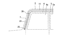
図1は、車両1を左斜め前方から見た斜視図であり、車両1には、その車体2のルーフ3の両側部に、フロントドア4およびリヤドア5で開閉されるドア開口部の上縁を構成する左右一対のルーフサイドレール6が車両前後方向に延在するように設けられており、これらルーフサイドレール6の前端が左右のフロントピラー7に連なっている。この車両1では、フロントピラー7の立ち上がり角度が極めて大きくなっている。
<Example 1>
First, a first embodiment of a vehicle airbag device according to the present invention will be described with reference to the drawings of FIGS.
FIG. 1 is a perspective view of a
そして、これらルーフサイドレール6およびフロントピラー7の車室内側に、それぞれカーテンエアバッグ装置10が設けられている。なお、図示の都合上、図1には、車体2の左側のルーフサイドレール6に沿って配置されたカーテンエアバッグ装置10のみが記載されている。
A
以下、カーテンエアバッグ装置10について詳述する。カーテンエアバッグ装置10は、エアバッグ本体11と、インフレータ12と、張力発生部としてのテザー20とを備えて構成されている。
Hereinafter, the
エアバッグ本体11は、長尺棒状に折り畳まれた形態で、ルーフサイドレール6の車室内側にルーフサイドレール6に沿って配置されており、展開時に、図5に示すようにフロントドア4の窓4aおよびリヤドア5の窓5aに沿って車室内にカーテン状に展開可能に取り付けられている。なお、エアバッグ本体11の上端はルーフサイドレール6に沿って固定されていて、展開時にもエアバッグ本体11の上端がルーフサイドレール6から離脱しないようにされている。
The airbag
インフレータ12は、エアバッグ本体11の車両前後方向の後部に設けられ、エアバッグ本体11の後端に接続されている。インフレータ12はガスを発生させて、そのガスをエアバッグ本体11に導入し、エアバッグ本体11を膨張展開させる。
The
テザー20は、展開後のエアバッグ本体11の位置を拘束するものであり、フロントピラー7の車室内側にフロントピラー7に沿って配置されている。
テザー20は、袋帯状をなし、エアバッグ本体11と同じ素材で形成されていて、機密性を有し、ガスの導入により膨張するとともに長さが短縮するように構成されている。図3はガス導入前のテザー20の平面図であり、テザー20は、例えば、1枚の基布21を2つ折りにして周囲を縫合することにより、1本の袋帯状に形成されたものであり、その長手方向(矢印L)の所定間隔毎に、幅方向(矢印W)の両端から幅方向中央に向かって接合部22が設けられていて、この接合部22によって表裏の基布21が接合され、テザー20の内部が長手方向に直列に並ぶ複数の袋部23に区画されている。なお、接合部22は表裏の基布21を縫合することによって形成してもよいし、接着剤等で接合して形成してもよい。また、幅方向の両側から延びる接合部22の間は非接合部24とされており、隣り合う袋部23を連通し、ガス通路として機能する。
The
The
そして、テザー20の長手方向の一端25はフロントピラー7の下部に固定され、他端26は、図5に示すように展開後のエアバッグ本体11の前端下部に接続されている。この他端26はエアバッグ本体11との間でガス流通が可能に接続されている。なお、テザー20とエアバッグ本体11とを同一の基布により一体に形成することも可能である。
One
ここで、テザー20の長さ変化の原理を説明する。図4は、図3A−Aに沿うテザー20の断面を模式的に示したものであり、上側はテザー20にガスが導入される前(以下、展開前という)の状態を示し、下側はガスが導入された後(以下、展開後という)の状態に示している。展開前のテザー20では表裏の基布21が互いに接近して重なり各袋部23は扁平な形態となる。これに対して、展開後は、各袋部23がガスの導入により膨張し、各袋部23において表裏の基布21が湾曲して互いに離間するため、テザー20の全長が展開前よりも縮まるのである。
そして、図2に示すように、テザー20は、展開前の形態で且つ長手方向に殆ど弛みのない直線状にされて、フロントピラー7に沿って配置されている。
Here, the principle of the length change of the
As shown in FIG. 2, the
このように構成されたカーテンエアバッグ装置10によれば、インフレータ12で発生したガスがエアバッグ本体11に導入されると、エアバッグ本体11が膨張し、図5に示すように、フロントドア4の窓4aおよびリヤドア5の窓5aに沿って車室内にカーテン状に展開する。
According to the
また、エアバッグ本体11の展開と同時に、エアバッグ本体11を介してテザー20の他端26からテザー20内に前記ガスが導入される。その結果、テザー20は膨張し、前述したようにその全長を短縮させながら、他端26側がエアバッグ本体11の展開に伴ってフロントピラー7から車室内に引き出され、最終的にエアバッグ本体11の展開後は、図5に示すように、車両前後方向に沿って略水平に直線状に延びる形態となる。つまり、展開後のエアバッグ本体11の前端下部が、長さを短縮させたテザー20によって、フロントピラー7の下部に連結されるので、エアバッグ本体11はそれ以上後方に移動することができなくなる。
Simultaneously with the deployment of the
これを展開前後で長さが短縮しないテザーを用いた場合と比較すると、展開後にテザー20の長さが短縮した寸法分だけ、展開後のエアバッグ本体11を車両前方寄りに拘束することができることとなる。
したがって、この実施例1のカーテンエアバッグ装置10によれば、フロントピラー7の立ち上がり角度が大きな車両1であっても、展開後のエアバッグ本体11を適正な位置に拘束することができる。
Compared with the case where a tether whose length is not shortened before and after deployment is used, the
Therefore, according to the
<実施例2>
次に、この発明に係る車両用エアバッグ装置の実施例2を図6から図8の図面を参照して説明する。
実施例1のカーテンエアバッグ装置10では、展開後のエアバッグ本体11の位置を拘束する張力発生部を、袋帯状のテザー20で構成したが、実施例2のカーテンエアバッグ装置10では、この張力発生部を副エアバッグ30で構成している。他の構成については実施例1と同じであるので、副エアバッグ30についてのみ以下に説明する。
<Example 2>
Next,
In the
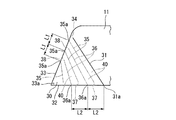
図7は、車両1に取り付ける前の副エアバッグ30の展開図であり、図6は、実施例1における図5に対応する図であり、車両1に取り付けられたカーテンエアバッグ装置10の展開後の状態を示している。
図7に示すように、副エアバッグ30はエアバッグ本体11と同一の基布で一体に形成されており、表裏の基布を接合してなる接合部31を境界として、車両前方側を副エアバッグ30、車両後方側をエアバッグ本体11に区画されている。
FIG. 7 is a development view of the
As shown in FIG. 7, the
接合部31は、副エアバッグ30の下辺32を始端として上辺33の手前まで直線的に延び、接合部31の先端と副エアバッグ30の上辺33との間に非接合部34が形成されている。この非接合部34によってエアバッグ本体11の内部と副エアバッグ30の内部とが連通され、ガスが流通可能となっている。
副エアバッグ30の下辺32と上辺33は同寸法に設定されており、折り畳んだときに下辺32が上辺33に重なるようにされている。
The joining
The
また、副エアバッグ30の内部は、表裏の基布を接合してなる複数の接合部によって、複数の袋部に区画されている。詳述すると、副エアバッグ30には、上辺33を始端として下辺32の手前まで直線的に延びる複数の第1接合部35と、下辺32を始端として上辺33の手前まで直線的に延びる複数の第2接合部36とが交互に配置されている。なお、前記した接合部31の隣には第1接合部35が配置されている。そして、接合部31とその隣の第1接合部35との間、および、隣接する第1接合部35と第2接合部36との間が、それぞれ袋部40となっている。
Moreover, the inside of the sub-airbag 30 is partitioned into a plurality of bag portions by a plurality of joint portions formed by joining the front and back base fabrics. More specifically, the
第1接合部35の先端と下辺32との間には非接合部37が形成され、第2接合部36の先端と上辺33との間には非接合部38が形成されており、これら非接合部37,38は隣り合う袋部40を連通し、ガス通路として機能する。
A
隣り合う第1接合部35の始端35a間の間隔L1は、接合部31の始端31aとその隣の第2接合部36の始端36aとの間隔L2、および隣り合う第2接合部36の始端36a間の間隔L2よりも小さく設定されている。つまり、隣り合う第1接合部35と第2接合部36の間隔(袋部40の幅)は、下辺32に接近するにしたがって大きくなる。
なお、接合部31,35,36は表裏の基布を縫合することによって形成してもよいし、接着剤等で接合して形成してもよい。
The distance L1 between the start ends 35a of the adjacent first
The
この副エアバッグ30は、上辺33の下端33aをフロントピラー7の下部に固定されるとともに、上辺33の全長をフロントピラー7に沿って固定され、エアバッグ本体11とともに折り畳まれた副エアバッグ30は、実施例1の場合と同様に、フロントピラー7の車室内側にフロントピラー7に沿って配置される。つまり、実施例2の場合も、車両1への取り付け状態は図2と同様である。
The
このように構成された副エアバッグ30では、インフレータ12で発生したガスがエアバッグ本体11に導入されると、エアバッグ本体11が膨張し、図6に示すように、フロントドア4の窓4aおよびリヤドア5の窓5aに沿って車室内にカーテン状に展開する。
In the
また、エアバッグ本体11の展開と同時に、エアバッグ本体11に導入されたガスが非接合部34を介して接合部31に隣接する袋部40に導入され、さらに非接合部37,38を次々に通って総ての袋部40にガスが導入されて、副エアバッグ30は膨張する。このとき、実施例1の場合と同様に、袋部40の膨張が副エアバッグ30の下辺32側の長さを短縮させる。つまり、上辺33はその全長がフロントピラー7に沿って固定されているので長さに変化はないが、上辺33から離れた部位では袋部40の膨張によって上辺33の下端33aからの長さが短縮する。特に、袋部40の幅が下辺32に接近するにしたがって大きくなっているので、下辺32に近づくにしたがって短縮幅が大きい。
Simultaneously with the development of the airbag
その結果、最終的にエアバッグ本体11の展開後は、図6に示すように、副エアバッグ30の下辺32は、その長さを短縮させて車両前後方向に沿って略水平に延びる形態となり、副エアバッグ30は、フロントピラー7とエアバッグ本体11の上部および下部とを結ぶ三角形状に展開される。
つまり、展開後のエアバッグ本体11の前端が、長さを短縮させた副エアバッグ30によって、フロントピラー7に連結されるので、エアバッグ本体11はそれ以上後方に移動することができなくなる。
As a result, after the
That is, since the front end of the
したがって、実施例2のカーテンエアバッグ装置10の場合も、実施例1と同様に、副エアバッグ30の長さが短縮した寸法分だけ、展開後のエアバッグ本体11を車両前方寄りに拘束することができる。
この実施例2のカーテンエアバッグ装置10によれば、フロントピラー7の立ち上がり角度が大きな車両1であっても、展開後のエアバッグ本体11を適正な位置に拘束することができる。
Therefore, in the case of the
According to the
図8は、副エアバッグ30における袋部の他の形態を示したものである。この形態では、副エアバッグ30の上辺33の上端33bを始端として複数の接合部41を放射状に形成し、隣り合う接合部41間を袋部42とする。また、接合部41は下辺32の手前で終端とし、接合部41の先端と下辺32との間を非接合部43として、この非接合部43を、エアバッグ本体11と袋部42とを連通するガス通路、および、隣り合う袋部42間を連通するガス通路とする。
このように構成した場合にも、前述した実施例2の場合と同様、展開後に副エアバッグ30の長さを短縮することができる。
FIG. 8 shows another form of the bag portion in the
Even in such a configuration, the length of the
〔他の実施例〕
なお、この発明は前述した実施例に限られるものではない。
例えば、前述した実施例1では、テザー20をエアバッグ本体11の前端下部に連結したが、エアバッグ本体11の位置を拘束する効果が得られる限り、エアバッグ本体11の他の部位に連結してもよい。
[Other Examples]
The present invention is not limited to the embodiment described above.
For example, in the first embodiment described above, the
1 車両
2 車体
7 フロントピラー
10 カーテンエアバッグ装置(車両用エアバッグ装置)
11 エアバッグ本体
12 インフレータ
20 テザー(張力発生部)
23 袋部
30 副エアバッグ(張力発生部)
40,42 袋部
DESCRIPTION OF
11
23
40, 42 bags
Claims (3)
折り畳み状態で車体の側部に取り付けられ前記インフレータからガスが導入されてカーテン状に展開するエアバッグ本体と、
前記エアバッグ本体および車体に取り付けられ前記エアバッグ本体の展開時に該エアバッグ本体の位置を拘束する張力発生部と、
を備える車両用エアバッグ装置であって、
前記張力発生部は、
前記エアバッグ本体の車両前後方向の端部に位置すると共に、前記インフレータからのガスが導入されて長手方向の長さを短縮する袋部を複数有し、これら総ての袋部が連通しており、前記インフレータからのガスが導入されることにより各袋部が膨張して長さが短縮することで、展開後の前記エアバッグ本体を車両前後方向に拘束することを特徴とする車両用エアバッグ装置。 An inflator that generates gas;
An air bag body to expand the gas is introduced Curtain shape from the inflator is attached to the vehicle body side in a folded state,
A tension generator attached to the airbag body and the vehicle body to restrain the position of the airbag body when the airbag body is deployed;
A vehicle airbag device comprising:
The tension generator is
The airbag main body has a plurality of bag portions that are positioned at the vehicle front-rear direction end portions and that are introduced with gas from the inflator to shorten the length in the longitudinal direction , and all the bag portions communicate with each other. And the air bag body is restrained in the vehicle front-rear direction by inflating each bag portion and reducing its length by introducing the gas from the inflator. Bag device.
Priority Applications (1)
| Application Number | Priority Date | Filing Date | Title |
|---|---|---|---|
| JP2009291618A JP5244776B2 (en) | 2009-12-24 | 2009-12-24 | Airbag device |
Applications Claiming Priority (1)
| Application Number | Priority Date | Filing Date | Title |
|---|---|---|---|
| JP2009291618A JP5244776B2 (en) | 2009-12-24 | 2009-12-24 | Airbag device |
Publications (2)
| Publication Number | Publication Date |
|---|---|
| JP2011131667A JP2011131667A (en) | 2011-07-07 |
| JP5244776B2 true JP5244776B2 (en) | 2013-07-24 |
Family
ID=44344892
Family Applications (1)
| Application Number | Title | Priority Date | Filing Date |
|---|---|---|---|
| JP2009291618A Active JP5244776B2 (en) | 2009-12-24 | 2009-12-24 | Airbag device |
Country Status (1)
| Country | Link |
|---|---|
| JP (1) | JP5244776B2 (en) |
Cited By (1)
| Publication number | Priority date | Publication date | Assignee | Title |
|---|---|---|---|---|
| KR20150112015A (en) * | 2013-02-28 | 2015-10-06 | 도요타 지도샤(주) | Head-protecting airbag device and method of folding airbag thereof |
Families Citing this family (3)
| Publication number | Priority date | Publication date | Assignee | Title |
|---|---|---|---|---|
| JP5973815B2 (en) * | 2012-07-06 | 2016-08-23 | オートリブ ディベロップメント エービー | Vehicle curtain airbag and vehicle curtain airbag mounting structure |
| JP6024338B2 (en) * | 2012-09-24 | 2016-11-16 | 三菱自動車工業株式会社 | Curtain airbag device |
| JP2014065329A (en) * | 2012-09-24 | 2014-04-17 | Mitsubishi Motors Corp | Curtain airbag device |
Family Cites Families (2)
| Publication number | Priority date | Publication date | Assignee | Title |
|---|---|---|---|---|
| DE29605897U1 (en) * | 1996-03-29 | 1996-07-25 | Trw Repa Gmbh | Gas bag |
| DE29605896U1 (en) * | 1996-03-29 | 1996-07-25 | Trw Repa Gmbh | Side impact protection device for vehicle occupants |
-
2009
- 2009-12-24 JP JP2009291618A patent/JP5244776B2/en active Active
Cited By (2)
| Publication number | Priority date | Publication date | Assignee | Title |
|---|---|---|---|---|
| KR20150112015A (en) * | 2013-02-28 | 2015-10-06 | 도요타 지도샤(주) | Head-protecting airbag device and method of folding airbag thereof |
| KR101659851B1 (en) | 2013-02-28 | 2016-09-26 | 도요타 지도샤(주) | Head-protecting airbag device and method of folding airbag thereof |
Also Published As
| Publication number | Publication date |
|---|---|
| JP2011131667A (en) | 2011-07-07 |
Similar Documents
| Publication | Publication Date | Title |
|---|---|---|
| JP6225179B2 (en) | Curtain airbag device for vehicle and mounting structure thereof | |
| JP6115907B2 (en) | Knee airbag module | |
| US20160046253A1 (en) | Airbag for knee airbag apparatus | |
| US20090134611A1 (en) | Knee airbag | |
| WO2007099667A1 (en) | Airbag and airbag device | |
| JP2011057208A (en) | Airbag | |
| WO2016121195A1 (en) | Vehicular seat | |
| WO2007099668A1 (en) | Airbag and airbag device | |
| JP5640686B2 (en) | Vehicle occupant protection device | |
| KR102227852B1 (en) | Curtain air bag apparatus and method of manufacturing the same | |
| JP5746666B2 (en) | Curtain airbag for vehicle and mounting structure thereof | |
| JP5244776B2 (en) | Airbag device | |
| US20080036189A1 (en) | Airbag | |
| JP2014054939A (en) | Air bag, air bag device and air bag mounting structure | |
| JP6420157B2 (en) | Airbag | |
| JP2011073562A (en) | Air bag, and air bag device | |
| JP2015039928A (en) | Air bag | |
| JP6004577B2 (en) | Airbag | |
| JP5550382B2 (en) | Airbag | |
| JP6404542B2 (en) | Curtain airbag and curtain airbag device | |
| JP2016124497A (en) | Air bag | |
| JP6088037B2 (en) | Mounting structure for curtain airbag for vehicle | |
| JP2009255726A (en) | Occupant crash protection device for vehicle | |
| JP5943767B2 (en) | Curtain airbag for vehicle and method for manufacturing the same | |
| JP2014091498A (en) | Air bag |
Legal Events
| Date | Code | Title | Description |
|---|---|---|---|
| A621 | Written request for application examination |
Free format text: JAPANESE INTERMEDIATE CODE: A621 Effective date: 20111125 |
|
| A521 | Written amendment |
Free format text: JAPANESE INTERMEDIATE CODE: A523 Effective date: 20120522 |
|
| A977 | Report on retrieval |
Free format text: JAPANESE INTERMEDIATE CODE: A971007 Effective date: 20121127 |
|
| A131 | Notification of reasons for refusal |
Free format text: JAPANESE INTERMEDIATE CODE: A131 Effective date: 20121204 |
|
| A521 | Written amendment |
Free format text: JAPANESE INTERMEDIATE CODE: A523 Effective date: 20130204 |
|
| TRDD | Decision of grant or rejection written | ||
| A01 | Written decision to grant a patent or to grant a registration (utility model) |
Free format text: JAPANESE INTERMEDIATE CODE: A01 Effective date: 20130312 |
|
| A61 | First payment of annual fees (during grant procedure) |
Free format text: JAPANESE INTERMEDIATE CODE: A61 Effective date: 20130408 |
|
| FPAY | Renewal fee payment (prs date is renewal date of database) |
Free format text: PAYMENT UNTIL: 20160412 Year of fee payment: 3 |
|
| R150 | Certificate of patent (=grant) or registration of utility model |
Free format text: JAPANESE INTERMEDIATE CODE: R150 |