JP5243577B2 - In-vivo stent - Google Patents
In-vivo stent Download PDFInfo
- Publication number
- JP5243577B2 JP5243577B2 JP2011152670A JP2011152670A JP5243577B2 JP 5243577 B2 JP5243577 B2 JP 5243577B2 JP 2011152670 A JP2011152670 A JP 2011152670A JP 2011152670 A JP2011152670 A JP 2011152670A JP 5243577 B2 JP5243577 B2 JP 5243577B2
- Authority
- JP
- Japan
- Prior art keywords
- stent
- end side
- shared linear
- pattern
- wavy
- Prior art date
- Legal status (The legal status is an assumption and is not a legal conclusion. Google has not performed a legal analysis and makes no representation as to the accuracy of the status listed.)
- Active
Links
- 238000001727 in vivo Methods 0.000 title claims description 36
- 230000002093 peripheral effect Effects 0.000 claims description 6
- 238000003780 insertion Methods 0.000 claims description 5
- 230000037431 insertion Effects 0.000 claims description 5
- 229910052751 metal Inorganic materials 0.000 description 44
- 239000002184 metal Substances 0.000 description 44
- 239000000463 material Substances 0.000 description 34
- 229910045601 alloy Inorganic materials 0.000 description 26
- 239000000956 alloy Substances 0.000 description 26
- 239000003550 marker Substances 0.000 description 26
- 238000011161 development Methods 0.000 description 24
- 230000018109 developmental process Effects 0.000 description 24
- 238000000034 method Methods 0.000 description 23
- 238000010438 heat treatment Methods 0.000 description 21
- 239000000758 substrate Substances 0.000 description 20
- 230000008569 process Effects 0.000 description 18
- 210000004204 blood vessel Anatomy 0.000 description 13
- 230000008602 contraction Effects 0.000 description 12
- 238000007517 polishing process Methods 0.000 description 12
- 238000005452 bending Methods 0.000 description 10
- 239000000126 substance Substances 0.000 description 10
- 239000011248 coating agent Substances 0.000 description 8
- 238000000576 coating method Methods 0.000 description 8
- 238000012545 processing Methods 0.000 description 8
- 229910001220 stainless steel Inorganic materials 0.000 description 7
- 239000010935 stainless steel Substances 0.000 description 7
- 229910010380 TiNi Inorganic materials 0.000 description 6
- 229910052737 gold Inorganic materials 0.000 description 6
- 239000010931 gold Substances 0.000 description 6
- BASFCYQUMIYNBI-UHFFFAOYSA-N platinum Chemical compound [Pt] BASFCYQUMIYNBI-UHFFFAOYSA-N 0.000 description 6
- 239000000057 synthetic resin Substances 0.000 description 6
- 229920003002 synthetic resin Polymers 0.000 description 6
- 230000004323 axial length Effects 0.000 description 5
- 238000010586 diagram Methods 0.000 description 5
- -1 for example Substances 0.000 description 5
- 230000006870 function Effects 0.000 description 5
- PCHJSUWPFVWCPO-UHFFFAOYSA-N gold Chemical compound [Au] PCHJSUWPFVWCPO-UHFFFAOYSA-N 0.000 description 5
- 229910052759 nickel Inorganic materials 0.000 description 5
- 238000007747 plating Methods 0.000 description 5
- 208000031481 Pathologic Constriction Diseases 0.000 description 4
- 238000005422 blasting Methods 0.000 description 4
- 239000002872 contrast media Substances 0.000 description 4
- 238000000227 grinding Methods 0.000 description 4
- 238000009499 grossing Methods 0.000 description 4
- 230000001678 irradiating effect Effects 0.000 description 4
- 239000002932 luster Substances 0.000 description 4
- 230000007246 mechanism Effects 0.000 description 4
- 239000000203 mixture Substances 0.000 description 4
- 229920005989 resin Polymers 0.000 description 4
- 239000011347 resin Substances 0.000 description 4
- 230000036262 stenosis Effects 0.000 description 4
- 208000037804 stenosis Diseases 0.000 description 4
- KDLHZDBZIXYQEI-UHFFFAOYSA-N Palladium Chemical compound [Pd] KDLHZDBZIXYQEI-UHFFFAOYSA-N 0.000 description 3
- 229910004337 Ti-Ni Inorganic materials 0.000 description 3
- 229910011209 Ti—Ni Inorganic materials 0.000 description 3
- 229910052782 aluminium Inorganic materials 0.000 description 3
- 238000000137 annealing Methods 0.000 description 3
- 239000000560 biocompatible material Substances 0.000 description 3
- 238000005520 cutting process Methods 0.000 description 3
- 238000001125 extrusion Methods 0.000 description 3
- KHYBPSFKEHXSLX-UHFFFAOYSA-N iminotitanium Chemical compound [Ti]=N KHYBPSFKEHXSLX-UHFFFAOYSA-N 0.000 description 3
- 229910052697 platinum Inorganic materials 0.000 description 3
- 238000005498 polishing Methods 0.000 description 3
- 238000013519 translation Methods 0.000 description 3
- 230000014616 translation Effects 0.000 description 3
- IJGRMHOSHXDMSA-UHFFFAOYSA-N Atomic nitrogen Chemical compound N#N IJGRMHOSHXDMSA-UHFFFAOYSA-N 0.000 description 2
- 239000004952 Polyamide Substances 0.000 description 2
- PPBRXRYQALVLMV-UHFFFAOYSA-N Styrene Chemical compound C=CC1=CC=CC=C1 PPBRXRYQALVLMV-UHFFFAOYSA-N 0.000 description 2
- WYTGDNHDOZPMIW-RCBQFDQVSA-N alstonine Natural products C1=CC2=C3C=CC=CC3=NC2=C2N1C[C@H]1[C@H](C)OC=C(C(=O)OC)[C@H]1C2 WYTGDNHDOZPMIW-RCBQFDQVSA-N 0.000 description 2
- 230000015572 biosynthetic process Effects 0.000 description 2
- 210000001715 carotid artery Anatomy 0.000 description 2
- 238000005229 chemical vapour deposition Methods 0.000 description 2
- 229920001577 copolymer Polymers 0.000 description 2
- 229920001971 elastomer Polymers 0.000 description 2
- 239000000806 elastomer Substances 0.000 description 2
- 210000001105 femoral artery Anatomy 0.000 description 2
- 238000002513 implantation Methods 0.000 description 2
- 239000011261 inert gas Substances 0.000 description 2
- 238000003698 laser cutting Methods 0.000 description 2
- 238000003754 machining Methods 0.000 description 2
- 229920003023 plastic Polymers 0.000 description 2
- 239000004033 plastic Substances 0.000 description 2
- 229920002647 polyamide Polymers 0.000 description 2
- 229920000728 polyester Polymers 0.000 description 2
- 229920000098 polyolefin Polymers 0.000 description 2
- 229920002635 polyurethane Polymers 0.000 description 2
- 239000004814 polyurethane Substances 0.000 description 2
- 210000003137 popliteal artery Anatomy 0.000 description 2
- 210000002254 renal artery Anatomy 0.000 description 2
- 229920002050 silicone resin Polymers 0.000 description 2
- 229910052715 tantalum Inorganic materials 0.000 description 2
- GUVRBAGPIYLISA-UHFFFAOYSA-N tantalum atom Chemical compound [Ta] GUVRBAGPIYLISA-UHFFFAOYSA-N 0.000 description 2
- 229910052721 tungsten Inorganic materials 0.000 description 2
- 229920002818 (Hydroxyethyl)methacrylate Polymers 0.000 description 1
- 229910001020 Au alloy Inorganic materials 0.000 description 1
- OKTJSMMVPCPJKN-UHFFFAOYSA-N Carbon Chemical compound [C] OKTJSMMVPCPJKN-UHFFFAOYSA-N 0.000 description 1
- 229910017518 Cu Zn Inorganic materials 0.000 description 1
- 229910017752 Cu-Zn Inorganic materials 0.000 description 1
- 229910017943 Cu—Zn Inorganic materials 0.000 description 1
- UFHFLCQGNIYNRP-UHFFFAOYSA-N Hydrogen Chemical compound [H][H] UFHFLCQGNIYNRP-UHFFFAOYSA-N 0.000 description 1
- WOBHKFSMXKNTIM-UHFFFAOYSA-N Hydroxyethyl methacrylate Chemical compound CC(=C)C(=O)OCCO WOBHKFSMXKNTIM-UHFFFAOYSA-N 0.000 description 1
- 229910001257 Nb alloy Inorganic materials 0.000 description 1
- 229910003310 Ni-Al Inorganic materials 0.000 description 1
- 229910001252 Pd alloy Inorganic materials 0.000 description 1
- 239000004698 Polyethylene Substances 0.000 description 1
- 229920000954 Polyglycolide Polymers 0.000 description 1
- 229910001260 Pt alloy Inorganic materials 0.000 description 1
- 229910001362 Ta alloys Inorganic materials 0.000 description 1
- RTAQQCXQSZGOHL-UHFFFAOYSA-N Titanium Chemical compound [Ti] RTAQQCXQSZGOHL-UHFFFAOYSA-N 0.000 description 1
- NRTOMJZYCJJWKI-UHFFFAOYSA-N Titanium nitride Chemical compound [Ti]#N NRTOMJZYCJJWKI-UHFFFAOYSA-N 0.000 description 1
- WAIPAZQMEIHHTJ-UHFFFAOYSA-N [Cr].[Co] Chemical class [Cr].[Co] WAIPAZQMEIHHTJ-UHFFFAOYSA-N 0.000 description 1
- 230000002965 anti-thrombogenic effect Effects 0.000 description 1
- 230000002785 anti-thrombosis Effects 0.000 description 1
- 239000003146 anticoagulant agent Substances 0.000 description 1
- 210000001367 artery Anatomy 0.000 description 1
- 229910052790 beryllium Inorganic materials 0.000 description 1
- 210000000013 bile duct Anatomy 0.000 description 1
- 229920006167 biodegradable resin Polymers 0.000 description 1
- 229920001400 block copolymer Polymers 0.000 description 1
- 230000036760 body temperature Effects 0.000 description 1
- 229910052796 boron Inorganic materials 0.000 description 1
- 229910052799 carbon Inorganic materials 0.000 description 1
- 238000003486 chemical etching Methods 0.000 description 1
- 229910052804 chromium Inorganic materials 0.000 description 1
- 239000011651 chromium Substances 0.000 description 1
- 229910017052 cobalt Inorganic materials 0.000 description 1
- 239000010941 cobalt Substances 0.000 description 1
- GUTLYIVDDKVIGB-UHFFFAOYSA-N cobalt atom Chemical compound [Co] GUTLYIVDDKVIGB-UHFFFAOYSA-N 0.000 description 1
- 230000006835 compression Effects 0.000 description 1
- 238000007906 compression Methods 0.000 description 1
- 238000001816 cooling Methods 0.000 description 1
- 229910052802 copper Inorganic materials 0.000 description 1
- TVZPLCNGKSPOJA-UHFFFAOYSA-N copper zinc Chemical compound [Cu].[Zn] TVZPLCNGKSPOJA-UHFFFAOYSA-N 0.000 description 1
- 230000007797 corrosion Effects 0.000 description 1
- 238000005260 corrosion Methods 0.000 description 1
- 230000006837 decompression Effects 0.000 description 1
- 201000010099 disease Diseases 0.000 description 1
- 208000037265 diseases, disorders, signs and symptoms Diseases 0.000 description 1
- 239000013013 elastic material Substances 0.000 description 1
- 238000009713 electroplating Methods 0.000 description 1
- 210000003238 esophagus Anatomy 0.000 description 1
- 238000005530 etching Methods 0.000 description 1
- 239000005038 ethylene vinyl acetate Substances 0.000 description 1
- 230000001747 exhibiting effect Effects 0.000 description 1
- 238000002474 experimental method Methods 0.000 description 1
- 229910052733 gallium Inorganic materials 0.000 description 1
- 239000007789 gas Substances 0.000 description 1
- 239000003353 gold alloy Substances 0.000 description 1
- BBKFSSMUWOMYPI-UHFFFAOYSA-N gold palladium Chemical compound [Pd].[Au] BBKFSSMUWOMYPI-UHFFFAOYSA-N 0.000 description 1
- 238000007731 hot pressing Methods 0.000 description 1
- 239000001257 hydrogen Substances 0.000 description 1
- 229910052739 hydrogen Inorganic materials 0.000 description 1
- 239000007943 implant Substances 0.000 description 1
- 229910052741 iridium Inorganic materials 0.000 description 1
- GKOZUEZYRPOHIO-UHFFFAOYSA-N iridium atom Chemical compound [Ir] GKOZUEZYRPOHIO-UHFFFAOYSA-N 0.000 description 1
- 229910052742 iron Inorganic materials 0.000 description 1
- 229910052745 lead Inorganic materials 0.000 description 1
- 230000003902 lesion Effects 0.000 description 1
- 238000011068 loading method Methods 0.000 description 1
- 210000003141 lower extremity Anatomy 0.000 description 1
- 238000012423 maintenance Methods 0.000 description 1
- 229910052748 manganese Inorganic materials 0.000 description 1
- 230000000873 masking effect Effects 0.000 description 1
- 239000000178 monomer Substances 0.000 description 1
- 229910052758 niobium Inorganic materials 0.000 description 1
- 239000010955 niobium Substances 0.000 description 1
- 229910052757 nitrogen Inorganic materials 0.000 description 1
- 210000000056 organ Anatomy 0.000 description 1
- 229910052763 palladium Inorganic materials 0.000 description 1
- HWLDNSXPUQTBOD-UHFFFAOYSA-N platinum-iridium alloy Chemical compound [Ir].[Pt] HWLDNSXPUQTBOD-UHFFFAOYSA-N 0.000 description 1
- 229920001200 poly(ethylene-vinyl acetate) Polymers 0.000 description 1
- 229920000747 poly(lactic acid) Polymers 0.000 description 1
- 229920000573 polyethylene Polymers 0.000 description 1
- 239000004633 polyglycolic acid Substances 0.000 description 1
- 229920002338 polyhydroxyethylmethacrylate Polymers 0.000 description 1
- 239000004626 polylactic acid Substances 0.000 description 1
- 229920000642 polymer Polymers 0.000 description 1
- 229920000915 polyvinyl chloride Polymers 0.000 description 1
- 239000004800 polyvinyl chloride Substances 0.000 description 1
- 239000010970 precious metal Substances 0.000 description 1
- 238000003825 pressing Methods 0.000 description 1
- 230000009467 reduction Effects 0.000 description 1
- 238000011160 research Methods 0.000 description 1
- 208000037803 restenosis Diseases 0.000 description 1
- 229910001285 shape-memory alloy Inorganic materials 0.000 description 1
- 229910052710 silicon Inorganic materials 0.000 description 1
- HBMJWWWQQXIZIP-UHFFFAOYSA-N silicon carbide Chemical compound [Si+]#[C-] HBMJWWWQQXIZIP-UHFFFAOYSA-N 0.000 description 1
- 229910010271 silicon carbide Inorganic materials 0.000 description 1
- 238000004544 sputter deposition Methods 0.000 description 1
- 230000000638 stimulation Effects 0.000 description 1
- 238000005482 strain hardening Methods 0.000 description 1
- 229920001169 thermoplastic Polymers 0.000 description 1
- 229920001187 thermosetting polymer Polymers 0.000 description 1
- 239000004416 thermosoftening plastic Substances 0.000 description 1
- 229910052718 tin Inorganic materials 0.000 description 1
- 229910052719 titanium Inorganic materials 0.000 description 1
- 239000010936 titanium Substances 0.000 description 1
- 210000003437 trachea Anatomy 0.000 description 1
- WFKWXMTUELFFGS-UHFFFAOYSA-N tungsten Chemical compound [W] WFKWXMTUELFFGS-UHFFFAOYSA-N 0.000 description 1
- 239000010937 tungsten Substances 0.000 description 1
- 238000002604 ultrasonography Methods 0.000 description 1
- 210000003708 urethra Anatomy 0.000 description 1
- 229910052720 vanadium Inorganic materials 0.000 description 1
- 238000007740 vapor deposition Methods 0.000 description 1
- 229910052725 zinc Inorganic materials 0.000 description 1
- 229910052726 zirconium Inorganic materials 0.000 description 1
Images


Classifications
-
- A—HUMAN NECESSITIES
- A61—MEDICAL OR VETERINARY SCIENCE; HYGIENE
- A61F—FILTERS IMPLANTABLE INTO BLOOD VESSELS; PROSTHESES; DEVICES PROVIDING PATENCY TO, OR PREVENTING COLLAPSING OF, TUBULAR STRUCTURES OF THE BODY, e.g. STENTS; ORTHOPAEDIC, NURSING OR CONTRACEPTIVE DEVICES; FOMENTATION; TREATMENT OR PROTECTION OF EYES OR EARS; BANDAGES, DRESSINGS OR ABSORBENT PADS; FIRST-AID KITS
- A61F2/00—Filters implantable into blood vessels; Prostheses, i.e. artificial substitutes or replacements for parts of the body; Appliances for connecting them with the body; Devices providing patency to, or preventing collapsing of, tubular structures of the body, e.g. stents
- A61F2/82—Devices providing patency to, or preventing collapsing of, tubular structures of the body, e.g. stents
- A61F2/86—Stents in a form characterised by the wire-like elements; Stents in the form characterised by a net-like or mesh-like structure
- A61F2/90—Stents in a form characterised by the wire-like elements; Stents in the form characterised by a net-like or mesh-like structure characterised by a net-like or mesh-like structure
- A61F2/91—Stents in a form characterised by the wire-like elements; Stents in the form characterised by a net-like or mesh-like structure characterised by a net-like or mesh-like structure made from perforated sheet material or tubes, e.g. perforated by laser cuts or etched holes
- A61F2/915—Stents in a form characterised by the wire-like elements; Stents in the form characterised by a net-like or mesh-like structure characterised by a net-like or mesh-like structure made from perforated sheet material or tubes, e.g. perforated by laser cuts or etched holes with bands having a meander structure, adjacent bands being connected to each other
- A61F2002/91508—Stents in a form characterised by the wire-like elements; Stents in the form characterised by a net-like or mesh-like structure characterised by a net-like or mesh-like structure made from perforated sheet material or tubes, e.g. perforated by laser cuts or etched holes with bands having a meander structure, adjacent bands being connected to each other the meander having a difference in amplitude along the band
-
- A—HUMAN NECESSITIES
- A61—MEDICAL OR VETERINARY SCIENCE; HYGIENE
- A61F—FILTERS IMPLANTABLE INTO BLOOD VESSELS; PROSTHESES; DEVICES PROVIDING PATENCY TO, OR PREVENTING COLLAPSING OF, TUBULAR STRUCTURES OF THE BODY, e.g. STENTS; ORTHOPAEDIC, NURSING OR CONTRACEPTIVE DEVICES; FOMENTATION; TREATMENT OR PROTECTION OF EYES OR EARS; BANDAGES, DRESSINGS OR ABSORBENT PADS; FIRST-AID KITS
- A61F2/00—Filters implantable into blood vessels; Prostheses, i.e. artificial substitutes or replacements for parts of the body; Appliances for connecting them with the body; Devices providing patency to, or preventing collapsing of, tubular structures of the body, e.g. stents
- A61F2/82—Devices providing patency to, or preventing collapsing of, tubular structures of the body, e.g. stents
- A61F2/86—Stents in a form characterised by the wire-like elements; Stents in the form characterised by a net-like or mesh-like structure
- A61F2/90—Stents in a form characterised by the wire-like elements; Stents in the form characterised by a net-like or mesh-like structure characterised by a net-like or mesh-like structure
- A61F2/91—Stents in a form characterised by the wire-like elements; Stents in the form characterised by a net-like or mesh-like structure characterised by a net-like or mesh-like structure made from perforated sheet material or tubes, e.g. perforated by laser cuts or etched holes
- A61F2/915—Stents in a form characterised by the wire-like elements; Stents in the form characterised by a net-like or mesh-like structure characterised by a net-like or mesh-like structure made from perforated sheet material or tubes, e.g. perforated by laser cuts or etched holes with bands having a meander structure, adjacent bands being connected to each other
- A61F2002/91516—Stents in a form characterised by the wire-like elements; Stents in the form characterised by a net-like or mesh-like structure characterised by a net-like or mesh-like structure made from perforated sheet material or tubes, e.g. perforated by laser cuts or etched holes with bands having a meander structure, adjacent bands being connected to each other the meander having a change in frequency along the band
-
- A—HUMAN NECESSITIES
- A61—MEDICAL OR VETERINARY SCIENCE; HYGIENE
- A61F—FILTERS IMPLANTABLE INTO BLOOD VESSELS; PROSTHESES; DEVICES PROVIDING PATENCY TO, OR PREVENTING COLLAPSING OF, TUBULAR STRUCTURES OF THE BODY, e.g. STENTS; ORTHOPAEDIC, NURSING OR CONTRACEPTIVE DEVICES; FOMENTATION; TREATMENT OR PROTECTION OF EYES OR EARS; BANDAGES, DRESSINGS OR ABSORBENT PADS; FIRST-AID KITS
- A61F2/00—Filters implantable into blood vessels; Prostheses, i.e. artificial substitutes or replacements for parts of the body; Appliances for connecting them with the body; Devices providing patency to, or preventing collapsing of, tubular structures of the body, e.g. stents
- A61F2/82—Devices providing patency to, or preventing collapsing of, tubular structures of the body, e.g. stents
- A61F2/86—Stents in a form characterised by the wire-like elements; Stents in the form characterised by a net-like or mesh-like structure
- A61F2/90—Stents in a form characterised by the wire-like elements; Stents in the form characterised by a net-like or mesh-like structure characterised by a net-like or mesh-like structure
- A61F2/91—Stents in a form characterised by the wire-like elements; Stents in the form characterised by a net-like or mesh-like structure characterised by a net-like or mesh-like structure made from perforated sheet material or tubes, e.g. perforated by laser cuts or etched holes
- A61F2/915—Stents in a form characterised by the wire-like elements; Stents in the form characterised by a net-like or mesh-like structure characterised by a net-like or mesh-like structure made from perforated sheet material or tubes, e.g. perforated by laser cuts or etched holes with bands having a meander structure, adjacent bands being connected to each other
- A61F2002/91525—Stents in a form characterised by the wire-like elements; Stents in the form characterised by a net-like or mesh-like structure characterised by a net-like or mesh-like structure made from perforated sheet material or tubes, e.g. perforated by laser cuts or etched holes with bands having a meander structure, adjacent bands being connected to each other within the whole structure different bands showing different meander characteristics, e.g. frequency or amplitude
-
- A—HUMAN NECESSITIES
- A61—MEDICAL OR VETERINARY SCIENCE; HYGIENE
- A61F—FILTERS IMPLANTABLE INTO BLOOD VESSELS; PROSTHESES; DEVICES PROVIDING PATENCY TO, OR PREVENTING COLLAPSING OF, TUBULAR STRUCTURES OF THE BODY, e.g. STENTS; ORTHOPAEDIC, NURSING OR CONTRACEPTIVE DEVICES; FOMENTATION; TREATMENT OR PROTECTION OF EYES OR EARS; BANDAGES, DRESSINGS OR ABSORBENT PADS; FIRST-AID KITS
- A61F2/00—Filters implantable into blood vessels; Prostheses, i.e. artificial substitutes or replacements for parts of the body; Appliances for connecting them with the body; Devices providing patency to, or preventing collapsing of, tubular structures of the body, e.g. stents
- A61F2/82—Devices providing patency to, or preventing collapsing of, tubular structures of the body, e.g. stents
- A61F2/86—Stents in a form characterised by the wire-like elements; Stents in the form characterised by a net-like or mesh-like structure
- A61F2/90—Stents in a form characterised by the wire-like elements; Stents in the form characterised by a net-like or mesh-like structure characterised by a net-like or mesh-like structure
- A61F2/91—Stents in a form characterised by the wire-like elements; Stents in the form characterised by a net-like or mesh-like structure characterised by a net-like or mesh-like structure made from perforated sheet material or tubes, e.g. perforated by laser cuts or etched holes
- A61F2/915—Stents in a form characterised by the wire-like elements; Stents in the form characterised by a net-like or mesh-like structure characterised by a net-like or mesh-like structure made from perforated sheet material or tubes, e.g. perforated by laser cuts or etched holes with bands having a meander structure, adjacent bands being connected to each other
- A61F2002/91533—Stents in a form characterised by the wire-like elements; Stents in the form characterised by a net-like or mesh-like structure characterised by a net-like or mesh-like structure made from perforated sheet material or tubes, e.g. perforated by laser cuts or etched holes with bands having a meander structure, adjacent bands being connected to each other characterised by the phase between adjacent bands
-
- A—HUMAN NECESSITIES
- A61—MEDICAL OR VETERINARY SCIENCE; HYGIENE
- A61F—FILTERS IMPLANTABLE INTO BLOOD VESSELS; PROSTHESES; DEVICES PROVIDING PATENCY TO, OR PREVENTING COLLAPSING OF, TUBULAR STRUCTURES OF THE BODY, e.g. STENTS; ORTHOPAEDIC, NURSING OR CONTRACEPTIVE DEVICES; FOMENTATION; TREATMENT OR PROTECTION OF EYES OR EARS; BANDAGES, DRESSINGS OR ABSORBENT PADS; FIRST-AID KITS
- A61F2/00—Filters implantable into blood vessels; Prostheses, i.e. artificial substitutes or replacements for parts of the body; Appliances for connecting them with the body; Devices providing patency to, or preventing collapsing of, tubular structures of the body, e.g. stents
- A61F2/82—Devices providing patency to, or preventing collapsing of, tubular structures of the body, e.g. stents
- A61F2/86—Stents in a form characterised by the wire-like elements; Stents in the form characterised by a net-like or mesh-like structure
- A61F2/90—Stents in a form characterised by the wire-like elements; Stents in the form characterised by a net-like or mesh-like structure characterised by a net-like or mesh-like structure
- A61F2/91—Stents in a form characterised by the wire-like elements; Stents in the form characterised by a net-like or mesh-like structure characterised by a net-like or mesh-like structure made from perforated sheet material or tubes, e.g. perforated by laser cuts or etched holes
- A61F2/915—Stents in a form characterised by the wire-like elements; Stents in the form characterised by a net-like or mesh-like structure characterised by a net-like or mesh-like structure made from perforated sheet material or tubes, e.g. perforated by laser cuts or etched holes with bands having a meander structure, adjacent bands being connected to each other
- A61F2002/9155—Adjacent bands being connected to each other
-
- A—HUMAN NECESSITIES
- A61—MEDICAL OR VETERINARY SCIENCE; HYGIENE
- A61F—FILTERS IMPLANTABLE INTO BLOOD VESSELS; PROSTHESES; DEVICES PROVIDING PATENCY TO, OR PREVENTING COLLAPSING OF, TUBULAR STRUCTURES OF THE BODY, e.g. STENTS; ORTHOPAEDIC, NURSING OR CONTRACEPTIVE DEVICES; FOMENTATION; TREATMENT OR PROTECTION OF EYES OR EARS; BANDAGES, DRESSINGS OR ABSORBENT PADS; FIRST-AID KITS
- A61F2230/00—Geometry of prostheses classified in groups A61F2/00 - A61F2/26 or A61F2/82 or A61F9/00 or A61F11/00 or subgroups thereof
- A61F2230/0002—Two-dimensional shapes, e.g. cross-sections
- A61F2230/0028—Shapes in the form of latin or greek characters
- A61F2230/0054—V-shaped
Abstract
Description
本発明は、血管、胆管、気管、食道、尿道、その他の臓器などの管腔内に生じた狭窄部もしくは閉塞部の治療に使用する生体内留置用ステントに関する。 The present invention relates to an in-vivo stent for use in the treatment of stenosis or occlusion occurring in lumens of blood vessels, bile ducts, trachea, esophagus, urethra, and other organs.
ステントは、血管あるいは他の生体内管腔が狭窄若しくは閉塞する事によって生じる様々な疾患を治療するために、その狭窄若しくは閉塞部位を拡張し、その内腔を確保するために留置される管状の医療用具である。ステントは、体外から体内に挿入するため、挿入時には直径が小さく、目的の狭窄若しくは閉塞部位で拡張もしくは復元させて直径を大きくし、大きくなった状態にて管腔を保持するものである。ステントは、機能及び拡張様式によって、セルフエクスパンダブルステントとバルーンエクスパンダブルステントに区別される。バルーンエクスパンダブルステントはステント自体に拡張機能はなく、ステントを目的部位に挿入した後、ステント内にバルーンを位置させてバルーンを拡張させ、バルーンの拡張力によりステントを拡張(塑性変形)させ目的管腔の内面に密着させて固定する。 Stents are tubular tubes that are placed to expand the stenosis or occlusion site and secure the lumen to treat various diseases caused by stenosis or occlusion of blood vessels or other in vivo lumens. It is a medical device. Since the stent is inserted from the outside of the body into the body, the diameter is small at the time of insertion. The stent is expanded or restored at a target stenosis or occlusion site to increase the diameter, and the lumen is held in a large state. Stents are classified into self-expandable stents and balloon expandable stents according to function and expansion mode. The balloon expandable stent has no expansion function in the stent itself. After inserting the stent into the target site, the balloon is positioned in the stent to expand the balloon, and the stent is expanded (plastic deformation) by the expansion force of the balloon. Fix it in close contact with the inner surface of the lumen.
このタイプのステントでは、上記のようなステントの拡張作業が必要になる。一方、セルフエクスパンダブルステントは基本的に弾性のある素材で作られており、大きさは拡張された最終形状で作られる。セルフエクスパンダブルステントは、ステントを体内に導入するためには、小さく折りたたんで、その形状を拘束する部材(ほとんどの場合はプラスチック製チューブ)の中に入れられ、その部材即ちチューブごと体内に導入し、目的部位でチューブから放出することで、ステントがその弾性により自分自身で拡張する。 This type of stent requires the above-described stent expansion operation. On the other hand, self-expandable stents are basically made of an elastic material and are sized in an expanded final shape. In order to introduce a stent into the body, a self-expandable stent is folded into a small part and placed in a member (mostly a plastic tube) that constrains its shape, and the entire member, ie, the tube, is introduced into the body. When the stent is released from the tube at the target site, the stent expands by itself due to its elasticity.
セルフエクスパンダブルステントとしては、複数の支柱部を複数のループ部で接続してなる概ジグザグ状のパターンで形成された環状体を互いに接続部で連結して略円筒状に形成した形状のものが主流となっている。
特開平11−505441号公報(特許文献1)のものでは、波状環状体が、斜めに形成されたコネクターによって連結された構造となっている。
また、隣り合う蛇行要素若しくはジグザグ要素の頂点が隣り合う蛇行要素若しくはジグザグ要素の中に侵入しているタイプのステントもある。このタイプのものとして、例えば、特表2000−506753号公報(特許文献2)のものがある。また、特表2002−518087号公報(特許文献3)のものでは、上記の蛇行要素の頂点同士が軸に平行なコネクターにより接続されている。
また、蛇行要素若しくはジグザグ要素が平ループではなく螺旋状となっているタイプのステントがある。このタイプのステントとしては、先端から後端まで1本若しくは複数本で構成されているものである。例えば、特表2001−509702号公報(特許文献4)では、ステントの形状を保つためにジグザグ要素間を軸に平行なコネクターにより接続している。また、特開平8−196642号公報(特許文献5)のものでは、波線状環状体ではなく、複数の螺旋により構成している。
As a self-expandable stent, an annular body formed in a substantially zigzag pattern in which a plurality of struts are connected by a plurality of loops is connected to each other by a connecting part to form a substantially cylindrical shape. Has become the mainstream.
In the thing of Unexamined-Japanese-Patent No. 11-505441 (patent document 1), it has the structure where the wavy annular body was connected by the connector formed diagonally.
There is also a type of stent in which the vertices of adjacent serpentine elements or zigzag elements penetrate into adjacent serpentine elements or zigzag elements. As this type, for example, there is one disclosed in JP 2000-506753 A (Patent Document 2). Moreover, in the thing of the Japanese translations of PCT publication No. 2002-518087 gazette (patent document 3), the vertex of said meandering element is connected by the connector parallel to an axis | shaft.
In addition, there is a type of stent in which meandering elements or zigzag elements are spiral instead of flat loops. This type of stent is composed of one or a plurality of stents from the front end to the rear end. For example, in Japanese Translation of PCT International Publication No. 2001-509702 (Patent Document 4), zigzag elements are connected by a connector parallel to the axis in order to maintain the shape of the stent. Moreover, in the thing of Unexamined-Japanese-Patent No. 8-196642 (patent document 5), it is comprised not with a wavy-line annular body but with several spirals.
従来技術で述べた最近の全てのステントは、各要素間を接続するためにコネクターを用いている。コネクターは、単に要素間を接続するためのもので拡張力には貢献しない。
そこで、発明者が鋭意検討したところ、拡張力に貢献する要素だけで構成され、且つコネクターの働きも共有できる構成であれば、一定以上の拡張力を保持しつつ且つカバレッジの良いステントとなる可能性が有ることを知見した。
本発明の目的は、拡張力を実質的発現せず、かつ、ステントの湾曲時に影響を与える可能性のある接続部を持たず、十分な拡張力ならびに全体として均等な拡張力を有するステントを提供するものである。
All recent stents described in the prior art use connectors to connect each element. The connector is simply for connecting the elements and does not contribute to expansion.
As a result, the inventor has intensively studied and it is possible to provide a stent with a high coverage while maintaining a certain level of expansion force as long as it is composed only of elements that contribute to expansion force and can share the function of the connector. It was found that there is sex.
An object of the present invention is to provide a stent that does not substantially develop an expansion force, does not have a connection portion that may affect the bending of the stent, and has a sufficient expansion force and an overall equal expansion force. To do.
上記目的を達成するものは、以下のものである。
(1) 軸方向に複数の波線状環状体を備えるステントであって、前記波線状環状体は、前記ステントの軸方向の一端側に頂点を有する複数の一端側屈曲部および前記ステントの軸方向の他端側に頂点を有する複数の他端側屈曲部を有し、かつ、ステントの軸方向基端側に隣り合う波線状環状体は、前記ステントの軸方向一端側の波線状環状体における前記他端側屈曲部の1つの頂点もしくはその付近に始端を有し、該他端側屈曲部の前記頂点と前記一端側屈曲部の頂点間に終端を有し、隣り合う2つの前記波線状環状体の一部を構成する共有線状部を有し、該共有線状部により、隣り合う波状環状体が一体化しており、さらに、前記ステントは、前記ステントの中心軸に対して所定角度斜めに延びる第1パターン共有線状部と、前記ステントの中心軸に対して所定角度斜めにかつ前記第1パターン共有線状部と異なる方向に延びる第2パターン共有線状部を備えており、さらに、前記第1パターン共有線状部は、ステントの軸方向に対して、直線的となるように、かつ、前記第2パターン共有線状部も、ステントの軸方向に対して、直線的となるように配置されていることを特徴とする生体内留置用ステント。
(2) 前記ステントは、前記共有線状部の前記始端部位が形成する始端分岐部と、前記共有線状部の前記終端部位が形成する終端分岐部とを有するものである上記(1)に記載の生体内留置用ステント。
(3) 前記波線状環状体は、前記共有線状部の始端と他端側屈曲部の頂点間を連結する短線状部を有している上記(1)または(2)に記載の生体内留置用ステント。
(4) 前記波線状環状体は、前記共有線状部の終端と一端側屈曲部の頂点間を連結する短線状部を有している上記(1)ないし(3)のいずれかに記載の生体内留置用ステント。
What achieves the above object is as follows.
(1) A stent including a plurality of wavy annular bodies in the axial direction, wherein the wavy annular body includes a plurality of one end side bent portions having apexes on one end side in the axial direction of the stent and the axial direction of the stent. The wavy line-shaped annular body having a plurality of other end side bent portions having apexes on the other end side of the stent and adjacent to the axial base end side of the stent is a wavy line-shaped annular body on one end side in the axial direction of the stent. has one vertex or beginning to near the second end side bent portion, have a termination between the vertices of said apex of said other-end side bent portion and the one end side bent portions, two adjacent said wavy A shared linear portion constituting a part of the annular body , adjacent corrugated annular bodies are integrated by the shared linear portion, and the stent has a predetermined angle with respect to the central axis of the stent A first pattern shared linear portion extending obliquely, and the stent A second pattern shared linear portion extending obliquely at a predetermined angle with respect to the central axis of the first pattern shared linear portion and in a direction different from the first pattern shared linear portion. In vivo, wherein the second pattern-sharing linear portion is arranged so as to be linear with respect to the axial direction and is also linear with respect to the axial direction of the stent. Indwelling stent.
(2) In the above (1), the stent includes a start end branch portion formed by the start end portion of the shared linear portion and a terminal branch portion formed by the end portion of the shared linear portion. The stent for in-vivo indwelling described.
(3) The in-vivo body according to (1) or (2), wherein the wavy-line annular body has a short line-shaped portion that connects between the start end of the shared line-shaped portion and the apex of the other-end bent portion. Indwelling stent.
(4) The wavy line-shaped annular body according to any one of (1) to (3), wherein the wavy-line annular body includes a short line-shaped portion that connects the end of the shared line-shaped portion and the apex of the one-end-side bent portion. In vivo indwelling stent.
(5) 前記波線状環状体は、他の一端側屈曲部の頂点より一端側に突出する突出一端側頂点および他の他端側屈曲部の頂点より他端側に突出する突出他端側頂点を形成する大波部を有している上記(1)ないし(4)のいずれかに記載の生体内留置用ステント。
(6) 前記大波部における前記突出一端側頂点と前記突出他端側頂点間が、長線状部を構成している上記(5)に記載の生体内留置用ステント。
(7) 前記波線状環状体は、前記共有線状部の終端と他端側屈曲部の頂点間を連結する長線状部を有している上記(1)ないし(6)のいずれかに記載の生体内留置用ステント。
(8) 前記隣り合う波線状環状体間には、複数の共有線状部を備えている上記(1)ないし(7)のいずれかに記載の生体内留置用ステント。
(9) 前記隣り合う波線状環状体間には、複数の共有線状部を備えており、該複数の共有線状部は、前記ステントの中心軸に対して、向かい合うようにもしくはほぼ等角度となるように形成されている上記(1)ないし(7)のいずれかに記載の生体内留置用ステント。
(10) 前記波線状環状体は、複数の大波部を備えている上記(1)ないし(9)のいずれかに記載の生体内留置用ステント。
(11) 前記波線状環状体は、複数の大波部を備えており、該複数の大波部は、前記ステントの中心軸に対して、向かい合うようにもしくはほぼ等角度となるように形成されている上記(1)ないし(9)のいずれかに記載の生体内留置用ステント。
(12) 前記共有線状部の始端と他端側屈曲部の頂点間を連結する短線状部は、前記ステントの軸方向に連続せず、かつ複数の該短線状部は、ほぼ直線状となるように形成されている上記(1)ないし(11)のいずれかに記載の生体内留置用ステント。
(13) 前記波線状環状体の前記一端側屈曲部の頂点は、隣り合う一方の波線状環状体の他端側屈曲部間に形成される空間に侵入し、前記波線状環状体の他端側屈曲部の頂点は、隣り合う他方の波線状環状体の一端側屈曲部間に形成される空間に侵入している上記(1)ないし(12)のいずれかに記載の生体内留置用ステント。
(14) 前記ステントは、略円筒形状に形成され、生体内挿入時には縮径され、生体内留置時には縮径前の形状に復元可能な自己拡張型である上記(1)ないし(13)のいずれかに記載の生体内留置用ステント。
(15) 前記ステントは、略管状体に形成され、生体内管腔への挿入のための直径を有し、該管状体の内部より半径方向に広がる力が付加されたときに拡張可能なステントである上記(1)ないし(13)のいずれかに記載の生体内留置用ステント。
(5) The wavy line-shaped annular body protrudes from the apex of the other end-side bent portion to the one end side, and the protruding other end-side apex protrudes from the apex of the other end-side bent portion to the other end side. The in-vivo indwelling stent according to any one of the above (1) to (4), which has a large wave part that forms a tube.
(6) The in-vivo indwelling stent according to (5), wherein a portion between the protruding one-end apex and the protruding other-end apex in the large wave portion forms a long linear portion.
(7) The wavy line-shaped annular body according to any one of (1) to (6), wherein the wavy line-shaped annular body has a long line-shaped portion that connects the end of the shared line-shaped portion and the apex of the other-end-side bent portion. In vivo indwelling stent.
(8) The in-vivo stent according to any one of (1) to (7), wherein a plurality of shared linear portions are provided between the adjacent wavy annular bodies.
(9) A plurality of shared linear portions are provided between the adjacent wavy-line annular bodies, and the plurality of shared linear portions are opposed to or substantially equiangular with respect to the central axis of the stent. The in-vivo indwelling stent according to any one of (1) to (7), which is formed to be
(10) The indwelling stent according to any one of (1) to (9), wherein the wavy annular body includes a plurality of large wave portions.
(11) The wavy-line annular body includes a plurality of large wave portions, and the plurality of large wave portions are formed so as to face each other or substantially equiangular with respect to the central axis of the stent. The in-vivo stent according to any one of (1) to (9) above.
(12) The short line portion that connects between the beginning end of the shared linear portion and the apex of the bent portion on the other end side is not continuous in the axial direction of the stent, and the plurality of short line portions are substantially linear. The in-vivo indwelling stent according to any one of (1) to (11), which is formed as described above.
(13) The apex of the one end side bent portion of the wavy annular body enters a space formed between the other end side bent portions of the adjacent one of the wavy annular bodies, and the other end of the wavy annular body. The indwelling stent according to any one of the above (1) to (12), wherein the apex of the side bend portion enters a space formed between the one end bend portions of the other adjacent wavy annular body. .
(14) Any of the above (1) to (13), wherein the stent is formed in a substantially cylindrical shape, is reduced in diameter when inserted into a living body, and is self-expandable that can be restored to a shape before being reduced in diameter when placed in the living body. The stent for in-vivo indwelling.
(15) The stent is formed in a substantially tubular body, has a diameter for insertion into a lumen in a living body, and is expandable when a force that extends in a radial direction from the inside of the tubular body is applied. The in-vivo stent according to any one of (1) to (13) above.
(16) 前記第1パターン共有線状部の向きおよび前記第2パターン共有線状部の向きは、前記ステントの中心軸に対して、ほぼ対称となっている(1)ないし(15)のいずれかに記載の生体内留置用ステント。
(17) 前記第1パターン共有線状部と前記第2パターン共有線状部は、前記ステントの軸方向に対して交互となるように配置されている(1)ないし(16)のいずれかに記載の生体内留置用ステント。
(18) 前記第2パターン共有線状部は、前記第1パターン共有線状部の配置位置に対して、ステントの外周方向にずれた位置に配置されている(1)ないし(17)のいずれかに記載の生体内留置用ステント。
(19) 前記ステントは、両端に位置する波線状環状体と隣り合う波線状環状体とを接続する連結部を備えている(1)ないし(18)のいずれかに記載の生体内留置用ステント。
(20) 前記第1パターン共有線状部と前記第2パターン共有線状部は、軸方向に連続しないように配置されている(1)ないし(19)のいずれかに記載の生体内留置用ステント。
(16) The orientation of the first pattern shared linear portion and the orientation of the second pattern shared linear portion are substantially symmetric with respect to the central axis of the stent (1) to (15) The stent for in-vivo indwelling.
(17) In any one of (1) to (16), the first pattern shared linear portion and the second pattern shared linear portion are arranged so as to alternate with respect to the axial direction of the stent. The stent for in-vivo indwelling described.
(18) Any of (1) to (17), wherein the second pattern shared linear portion is disposed at a position shifted in an outer peripheral direction of the stent with respect to an arrangement position of the first pattern shared linear portion. The stent for in-vivo indwelling.
(19) The stent for in-vivo placement according to any one of (1) to (18), wherein the stent includes a connecting portion that connects a wavy annular body located at both ends and a neighboring wavy annular body. .
(20) The in-vivo indwelling device according to any one of (1) to (19), wherein the first pattern shared linear portion and the second pattern shared linear portion are arranged so as not to be continuous in the axial direction. Stent.
本発明の生体内留置用ステントは、軸方向に複数の波線状環状体を備えるステントであって、前記波線状環状体は、前記ステントの軸方向の一端側に頂点を有する複数の一端側屈曲部および前記ステントの軸方向の他端側に頂点を有する複数の他端側屈曲部を有し、かつ、ステントの軸方向基端側に隣り合う波線状環状体は、前記ステントの軸方向一端側の波線状環状体における前記他端側屈曲部の1つの頂点もしくはその付近に始端を有し、該他端側屈曲部の前記頂点と前記一端側屈曲部の頂点間に終端を有する共有線状部を有し、該共有線状部により、隣り合う波状環状体が一体化している。ステントは、拡張力を実質的発現せず、かつ、ステントの湾曲時に影響を与える可能性のある接続部を持たず、隣り合う波線状環状体が、共有線状部により一体化されているため、十分な拡張力ならびに全体として均等な拡張力を有する。 The in-vivo stent according to the present invention is a stent including a plurality of wavy annular bodies in the axial direction, and the wavy annular bodies are bent at one end side having apexes on one end side in the axial direction of the stent. And a wavy line-shaped annular body adjacent to the proximal end side in the axial direction of the stent has one end in the axial direction of the stent. A common line having a starting end at or near one apex of the other end side bend in the wavy annular body on the side, and an end between the apex of the other end bend and the apex of the one end bend Adjacent wavy annular bodies are integrated by the shared linear portion. Because the stent does not substantially exhibit expansion force, does not have a connection part that may affect the bending of the stent, and adjacent wavy annular bodies are integrated by the shared linear part. Sufficient expansion force as well as overall equal expansion force.
本発明の実施例のステントについて図面に示した実施例を用いて説明する。
図1は、本発明の実施例のステントの正面図である。図2は、図1に示したステントの展開図である。図3は、図1に示したステントを縮径させた状態のステントの展開図である。図4は、図1に示したステントの部分拡大図である。
本発明の生体内留置用ステント1は、軸方向に複数の波線状環状体2を備えるステントであって、波線状環状体2は、ステント1の軸方向の一端側に頂点2aを有する複数の一端側屈曲部およびステント1の軸方向の他端側に頂点2bを有する複数の他端側屈曲部を有し、かつ、ステント1の軸方向基端側に隣り合う波線状環状体2は、ステント1の軸方向一端側の波線状環状体2における他端側屈曲部の1つの頂点2bもしくはその付近に始端22を有し、他端側屈曲部の頂点2bと一端側屈曲部の頂点2a間に終端23を有する共有線状部21を有し、共有線状部21により、隣り合う波状環状体が一体化している。
本発明のステントは、部分的共有部を有することにより、隣り合う波線状環状体が一体化した複数の環状体からなるものであり、いわゆる接続部としてのみ設けられた部分を備えず、すべてが、拡張力を発揮する部分のみにより構成されている。
The stent of the Example of this invention is demonstrated using the Example shown on drawing.
FIG. 1 is a front view of a stent according to an embodiment of the present invention. FIG. 2 is a development view of the stent shown in FIG. FIG. 3 is a development view of the stent in a state where the diameter of the stent shown in FIG. 1 is reduced. FIG. 4 is a partially enlarged view of the stent shown in FIG.
The stent 1 for indwelling according to the present invention is a stent including a plurality of wavy
The stent of the present invention is composed of a plurality of annular bodies in which adjacent wavy annular bodies are integrated by having a partially shared portion, and does not include a portion provided only as a so-called connection portion, It is comprised only by the part which exhibits expansion power.
また、この実施例のステントは、略円筒形状に形成され、生体内挿入時には縮径され、生体内留置時には縮径前の形状に復元可能なステント、いわゆる自己拡張型ステントである 図1は、ステント1の拡張時の外観形状を示している。
ステント1を形成する波線状環状体2の数としては、図1に示すものでは、11となっている。波線状環状体2の数としては、ステントの長さによって相違するが、2〜150が好ましく、特に、5〜100が好ましい。
そして、各波線状環状体2は、ステント1の軸方向の一端側に頂点を有する複数の一端側屈曲部およびステント1の軸方向の他端側に頂点を有する複数の他端側屈曲部を有するとともに、環状に連続した無端の波線状体により構成されている。環状体2における一端側屈曲部と他端側屈曲部は、交互に形成されており、かつそれぞれの数は同じとなっている。1つの波線状環状体2における一端側屈曲部(他端側屈曲部)の数としては、図1に示すものでは、9つとなっている。一端側屈曲部(他端側屈曲部)の数としては、4〜20が好ましく、特に、6〜12が好ましい。そして、この実施例1のステントにおける波線状環状体2を形成する線状体は、常に湾曲しており、直線状部分が極めて少ないものとなっている。このため、環状体2を形成する線状体は十分な長さを有するため、拡張時における高い拡張力を発揮する。また、波線状環状体2の軸方向の長さとしては、1〜10mmが好ましく、特に、1.5〜5mmが好ましい。
The stent of this embodiment is a so-called self-expanding stent that is formed in a substantially cylindrical shape, is reduced in diameter when inserted into a living body, and can be restored to a shape before being reduced in diameter when placed in the living body. The external shape at the time of expansion of the stent 1 is shown.
The number of wavy
Each wavy-line
そして、この実施例のステント1では、図1、図2、図3および図4に示すように、各波線状環状体2は、他の一端側屈曲部の頂点2aより一端側に突出する突出一端側頂点2a1および他の他端側屈曲部の頂点より他端側突出する突出他端側頂点(この実施例では、始点と一致する)22を形成する大波部を有している。さらに、この実施例では、波線状環状体は、複数の大波部を備えている。このステントでは、1つの環状体が、9つの一端側屈曲部を備えており、大波部は、1つの環状体内に、3つ設けられている。そして、3つの大波部は、ステント1の中心軸に対して、ほぼ等角度となるように形成されている。
そして、ステント1の軸方向基端側に隣り合う波線状環状体2は、ステント1の軸方向一端側の波線状環状体2における他端側屈曲部の1つの頂点2bもしくはその付近に始端22を有し、他端側屈曲部の頂点2aと一端側屈曲部の頂点2b間に終端23を有する共有線状部21を有し、共有線状部21により、隣り合う波状環状体が一体化している。また、図1ないし図4に示すように、共有線状部は、隣り合う2つの波線状環状体の一部を構成している。
And in the stent 1 of this Example, as shown in FIG.1, FIG.2, FIG.3 and FIG. 4, each wavy-line
The wavy
具体的には、共有線状部21は、ステント1の軸方向一端側の波線状環状体2における他端側屈曲部の1つの頂点2bを始端22とするものであり、始端22と頂点2bは同じものとなっている。また、共有線状部21は、上記の頂点2b(始端22でもある)と連続する一端側屈曲部の頂点2a間に終端23を有する。特に、この実施例では、共有線状部21は、上記の頂点2b(始端22でもある)と連続する一端側屈曲部の頂点2a間のほぼ中点付近に終端を有するものとなっている。なお、この終端23の位置としては、中点に位置することが好ましいが、上記の頂点2b(始端22でもある)と連続する一端側屈曲部の頂点2a間の全長の1/100〜49/100程度いずれかの頂点側となる位置であってもよい。なお、この場合、この終端23の位置としては、中点より、頂点2a側にずれることが好ましい。
ステント1は、上記のような構成を有するため、共有線状部21の始端部位が形成する始端分岐部と、共有線状部21の終端部位が形成する終端分岐部とを有する。具体的には、始端分岐部は、始端22を分岐点として、一端側に向かって二股に分岐する形態となっており、終端分岐部は、終端23を分岐点として、他端側に向かって二股に分岐する形態となっている。
Specifically, the shared
Since the stent 1 has the above-described configuration, the stent 1 has a start end branch portion formed by the start end portion of the shared
さらに、この実施例のステント1では、大波部における突出一端側頂点2a1と突出他端側頂点(始端22と一致)間が、他の各頂点間を接続する線状部より長い長線状部となっている。そして、この長線状部の他端側端が、上記のように共有線状部の始端となっている。そして、この実施例では、大波部の一部に、共有線状部21が形成されている。
また、この実施例のステント1では、図2に示すように、各波線状環状体2は、共有線状部21の終端23と一端側屈曲部の頂点2a間を連結する短線状部26を有している。また、上記の短線状部26を有する環状体2と共有線状部21により一体化した環状体2は、図2に示すように、共有線状部21の始端22と他端側屈曲部の頂点2b間を連結する短線状部25と、共有線状部21の終端23と他端側屈曲部の他の頂点2b間を連結する長線状部24とを有している。
よって、大波部における突出一端側頂点(終端23と一致)と突出他端側頂点(他端側に隣り合う環状体と共有線状部の始端22と一致)間が、長線状部を構成している。つまり、ステント1では、軸方向に隣り合う共有線状部21は、軸方向一端側から見て、共有線状部21の終端23と隣り合う共有線状部21の始端22とが、長線状部24により接続された形態となっている。このため、図2に示すように、このステント1では、長線状部24と共有線状部21が繰り返されることにより構成されたジグザグ形態が、ステントの一端から他端側に向かって螺旋を形成するものとなっている。
Furthermore, in the stent 1 of this embodiment, the long linear portion between the protruding one end vertex 2a1 and the protruding other end vertex (matching the start end 22) in the large wave portion is longer than the linear portion connecting the other apexes. It has become. And the other end side end of this long linear part is the start end of a shared linear part as mentioned above. In this embodiment, the shared
Further, in the stent 1 of this embodiment, as shown in FIG. 2, each wavy-line
Therefore, a long line-shaped part is formed between the protruding one end apex (matching with the terminal end 23) and the protruding other end apex (matching with the annular body adjacent to the other end side and the starting
そして、このステントでは、いわゆる接続部がなく、接続部に起因する湾曲障害および拡張力低下といったことがなく、ステント全体として、均質な拡張保持力を発揮する。
そして、この実施例のステント1では、隣り合う波線状環状体間には、複数の共有線状部21を備えている。具体的には、隣り合う波線状環状体間には、3つの共有線状部21が設けられている。そして、3つの共有線状部21は、ステント1の中心軸に対して、ほぼ等角度となるように形成されている。
そして、ステント1では、共有線状部21の始端22と他端側屈曲部の頂点2b間を連結する短線状部25は、ステント1の軸方向に連続せず、かつ複数の短線状部25が、ほぼ直線状となるように形成されている。また、このステント1では、上述した短線状部25、26を除く線状部(長線状部およびその他線状部)は、図4に示すように、中間部付近に線状体の進行方向をほぼ平行にかつ若干変更する偏曲部32を備えている。この偏曲部32を有することにより、線状部長さも長くなるととともに、拡張力も高くなる。
In this stent, there is no so-called connection portion, and there is no bending failure or expansion force reduction due to the connection portion, and the entire stent exhibits a uniform expansion holding force.
And in the stent 1 of this Example, the some shared
In the stent 1, the short
さらに、このステント1では、長線状部24の長さ(すなわち、共有線状部21の終端23と共有線状部21の始端22間の長さ)と、共有線状部21と短線状部25を合わせた長さ(すなわち、共有線状部21の終端23から始端21を越えて頂点2bまでの長さ)を比較すると、長線状部24の方が若干長いものとなっている。このようにすることにより、頂点2bを隣り合う環状体の線状部33(具体的には、頂点2aと頂点2bを繋ぎ、線状共有部、分岐部のない通常の線状部)との過剰な近接を防止することができ、線状体が形成する閉鎖空間(図2に示すように、この実施例では、V字とM字を接続した閉鎖空間が形成されている)における幅のかたよりを少ないものとすることができ、高い拡張維持力を発揮する。
また、図2に示すように、波線状環状体2の一端側屈曲部の頂点2aは、隣り合う一方の波線状環状体の他端側屈曲部の頂点2b間に形成される空間に侵入しており、波線状環状体2の他端側屈曲部の頂点2bは、隣り合う他方の波線状環状体の一端側屈曲部の頂点2a間に形成される空間に侵入している。このようにすることにより、ステントを構成する線状体の長さを長くでき、かつ、線状体が形成する閉鎖空間(図2に示すように、この実施例では、V字とM字を接続した閉鎖空間が形成されている)の面積を小さいものとすることができ、高い拡張維持力を発揮する。
Furthermore, in this stent 1, the length of the long linear portion 24 (that is, the length between the
Further, as shown in FIG. 2, the apex 2a of the one end side bent portion of the wavy
さらに、この実施例のステント1では、図3に示す収縮状態では、周方向における隙間が殆どなく、各要素が並んでいる。このため、高いカバレッジを持つ。
また、図5に示すステント10のように、造影用マーカー11を設けることが好ましい。造影用マーカー11は、ステントの端部側に設けることが好ましい。特に、両端部側にそれぞれ設けることが好ましい。具体的には、図5に示すように、両端側にそれぞれ複数のマーカー11を設けることが好ましい。
この実施例のステント10では、ステントの一端部に位置する頂点部に形成された開口部27を有し、この開口部27を閉塞するようにマーカー11が固定されている。
このようなマーカーは、例えば、ステントに形成された小開口に、この小開口より若干小さい部分と大きい部分を有するX線造影用物質の円盤状部材を配置し両面より押圧して、リベット状に、かしめることにより取り付けられることが好ましい。
なお、造影用マーカーとしては、X線造影用、超音波造影用などどのようなものであってもよい。マーカーとしては、X線造影性物質、超音波造影性物質などの造影性物質により形成される。マーカーの形成材料としては、例えば、金、白金、タングステン、タンタル、イリジウム、パラジウムあるいはそれらの合金、あるいは金−パラジウム合金、白金−イリジウム、NiTiPd、NiTiAu等が好適である。
Furthermore, in the stent 1 of this embodiment, in the contracted state shown in FIG. 3, there are almost no gaps in the circumferential direction, and the elements are arranged. For this reason, it has high coverage.
Moreover, it is preferable to provide the
The
Such a marker is, for example, arranged in a small opening formed in a stent by placing a disk-shaped member of an X-ray contrast material having a portion slightly smaller and larger than this small opening and pressing it from both sides to form a rivet shape. It is preferable that it is attached by caulking.
The contrast marker may be any one such as for X-ray contrast and ultrasonic contrast. The marker is formed of a contrast material such as an X-ray contrast material or an ultrasound contrast material. As the marker forming material, for example, gold, platinum, tungsten, tantalum, iridium, palladium, or an alloy thereof, gold-palladium alloy, platinum-iridium, NiTiPd, NiTiAu, or the like is preferable.
また、ステントとしては、図6に示すようなパターンのステント20であってもよい。図6は、本発明のステントの他の実施例のパターンを説明するための説明図である。
このステント20と上述したステント1との相違は、各波線状環状体2において、いわゆる大波部が形成されておらず、各波がほぼ同じ大きさとなっている点である。また、図6の圧縮状体において、共有線状部21となっている部分の側面に空隙部が形成されている。
Further, the
The difference between the
また、ステントとしては、図7に示すようなパターンのステント30であってもよい。図7は、本発明のステントの他の実施例のパターンを説明するための説明図である。
このステント30と上述したステント1との相違は、1つの波線状環状体2における一端側屈曲部および他端側屈曲部の数、隣り合う環状体を一体化する共有線状部21の数のみである。このステント30では、1つの環状体2における一端側屈曲部および他端側屈曲部の数もステント1より少ない(具体的には、それぞれ8)ものとなっている。そして、1つの環状体2は、2つの大波部を有しており、2つの大波部は、ステントの中心軸に対して、向かい合う位置に設けられている。さらに、隣り合う2つの環状体2は、2つの共有線状部21により一体化されている。そして、2つの共有線状部21は、ステントの中心軸に対して、向かい合う位置に設けられている。
Moreover, as a stent, the
The difference between this
また、ステントとしては、図8に示すようなパターンのステント40であってもよい。図8は、本発明のステントの他の実施例のパターンを説明するための説明図である。
このステント40と上述したステント1との相違は、1つの波線状環状体2における一端側屈曲部および他端側屈曲部の数、隣り合う環状体を一体化する共有線状部21の数のみである。このステント40では、1つの環状体2における一端側屈曲部および他端側屈曲部の数もステント1より少ない(具体的には、それぞれ8)ものとなっている。そして、1つの環状体2は、4つの大波部を有しており、4つの大波部は、ステントの中心軸に対して、ほぼ等角度となるように設けられている。さらに、隣り合う2つの環状体2は、4つの共有線状部21により一体化されている。そして、4つの共有線状部21は、ステントの中心軸に対して、ほぼ等角度となるように設けられている。
そして、上述した全ての実施例のステントは、ステントの側面全体よりステントの中心方向に負荷をかけると縮径する。
Moreover, as a stent, the
The difference between this
The stents of all the embodiments described above are reduced in diameter when a load is applied from the entire side surface of the stent toward the center of the stent.
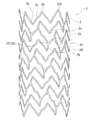
また、ステントとしては、図9ないし11に示すような、パターンのステント50であってもよい。図9は、本発明のステントの他の実施例の正面図である。図10は、図9に示したステントの展開図である。図11は、図9に示したステントを縮径させた状態のステントの展開図である。
このステント50と上述したステント1との相違は、1つの波線状環状体2における一端側屈曲部および他端側屈曲部の数、隣り合う環状体を一体化する共有線状部21の数、共有線状部の配置形態およびその向きなどである。
このステント50では、1つの環状体2における一端側屈曲部および他端側屈曲部の数はステント1より少ない(具体的には、それぞれ8)ものとなっており、軸方向には、11の環状体が配置されたものとなっており、隣り合う2つの環状体2、2つの共有線状部21(第1パターン共有線状部)もしくは2つの共有線状部41(第2パターン共有線状部)により一体化されている。そして、2つの共有線状部21は、ステントの中心軸に対して、向かい合う位置に設けられている。同様に、2つの共有線状部41も、ステントの中心軸に対して、向かい合う位置に設けられている。
The stent may be a patterned
The difference between the
In this
このステント50では、第1パターン共有線状部21と第2パターン共有線状部41が、ステントの軸方向に対して交互となるように配置されており、かつ、第1パターン共有線状部21と第2パターン共有線状部41が、軸方向に連続しないように配置されている。具体的には、第2パターン共有線状部41は、第1パターン共有線状部21の配置位置に対して、ステントの外周方向にずれた位置に配置されている。
また、ステント50では、第1パターン共有線状部21と第2パターン共有線状部41は、ステントの軸方向に対して斜めに延びるととともに、両者の向きが異なるもの(言い換えれば、ステントの中心軸に対して所定角度斜めに延びる第1パターン共有線状部21と、ステントの中心軸に対して所定角度斜めにかつ第1パターン共有線状部21と異なる方向に延びる第2パターン共有線状部41を備えるもの)となっている。
具体的に説明すると、このステント50では、1つの環状体2は、2つの大波部を有しており、2つの大波部は、ステントの中心軸に対して、向かい合う位置に設けられている。さらに、隣り合う2つの環状体2は、2つの共有線状部により一体化されている。さらに、このステント50では、第1パターン共有線状部21の終端は、線状部24により、他端側屈曲部と連結する形態となっており、同様に、第2のパターン共有線状部41の終端も、線状部24により、他端側屈曲部と連結する形態となっている。つまり、上述したステント1では、長線状部24は、軸方向に隣り合う2つの共有線状部(正確には、一方の共有線状部の終端と他方の線状共有部の始端)を連結していたのに対し、ステント50では、共有線状部同士を連結する形態とはなっていない。なお、共有線状部と連結する線状部24は、上述したステント1に比べて明確な長線状部となっていない。なお、この線状部24は、他の線状部より若干長い程度である。なお、この線状部24は、長線状部であってもよい。
In this
Further, in the
Specifically, in this
また、このステント50では、第1パターン共有線状部21に対して、ステントの軸方向に隣り合う第2パターン共有線状部41は、1つの一端側屈曲部と1つの他端側屈曲部分ずれた位置に設けられている。そして、ステントの軸方向に隣り合う2つの第1パターン共有線状部21および2つの第2パターン共有線状部41は、ステント50の中心軸に対してほぼ等角度に配置された状態となっている。このため、ステントは、全体においてほぼ均一の拡張力を発現可能である。
また、このステント50では、図10に示すように、第1パターン共有線状部21は、ステントの軸方向に対して、螺旋状となるように配置されたものとなっており、同様に、第2パターン共有線状部41も、ステントの軸方向に対して、螺旋状となるように配置されたものとなっている。
また、このステント50では、図10に示すように、ステントの軸方向に配置された11の波線状環状体を備えている。そして、第1パターン共有線状部21は、ステントの軸方向に対して、螺旋状となるように配置されたものとなっており、同様に、第2パターン共有線状部41も、ステントの軸方向に対して、螺旋状となるように配置されたものとなっている。具体的には、一つおきに隣り合う波線状環状体は、2つの第1パターン共有線状部21より連結されており、それぞれの第1パターン共有線状部21は、ステントの軸方向に螺旋状となるように配置されている。このため、第1パターン共有線状部21による2つの螺旋が形成されている。そして、一つの螺旋は、5つの第1パターン共有線状部21により構成される。また、同様に、一つおきに隣り合う波線状環状体(第1パターン共有線状部21により連結されていない)は、2つの第2パターン共有線状部41により連結されており、それぞれの第2パターン共有線状部41は、ステントの軸方向に螺旋状となるように配置されている。このため、第2パターン共有線状部41による2つの螺旋が形成されている。そして、一つの螺旋は、5つの第2パターン共有線状部41により構成されている。
Further, in this
Further, in this
In addition, the
また、上述したように、第1パターン共有線状部21と第2パターン共有線状部41は、ステントの軸方向に対して斜めに延びるとともに、両者の向きが異なるものとなっており、特に、両者の向きは、ステントの中心軸に対して、ほぼ対称であることが好ましい。このようにすることにより、ステントは、全体においてほぼ均一の拡張力を発現可能である。
なお、この実施例のステント50では、図10に示すように、波線状環状体2は、第1パターン共有線状部21の終端23と一端側屈曲部の頂点2a間を連結する短線状部26を有している。そして、この波線状環状体と隣り合う波線状環状体は、第1パターン共有線状部21の始端22と他端側屈曲部の頂点2b間を連結する短線状部25と、第2パターン共有線状部41の終端42と一端側屈曲部の頂点間を連結する短線状部47を有している。
そして、この実施例のステント50は、上述したステント1と構造が異なることにより、軸方向の伸び縮みに対する抵抗力を小さいものとすることができ、血管の変形に対する追従性が良好なものとなる。
In addition, as described above, the first pattern shared
In addition, in the
The
また、ステントとしては、図12ないし14に示すようなパターンのステント60であってもよい。図12は、本発明のステントの他の実施例の正面図である
。図13は、図12に示したステントの展開図である。図14は、図12に示したステントを縮径させた状態のステントの展開図である。
このステント60と上述したステント1との相違は、共有線状部の配置形態およびその向きなどである。このステント60では、共有線状部21(第1パターン共有線状部)および共有線状部41(第2パターン共有線状部)は、ステントの軸方向に対してほぼ直線上に配置されている。
このステント60では、1つの環状体2における一端側屈曲部および他端側屈曲部の数はステント1と同じ(具体的には、それぞれ9)であり、軸方向には、13の環状体が配置されたものとなっている。隣り合う2つの環状体2は、3つの共有線状部21(第1パターン共有線状部)もしくは3つの共有線状部41(第2パターン共有線状部)により一体化されている。そして、3つの共有線状部21は、ステントの中心軸に対して、ほぼ等角度に設けられている。同様に、3つの共有線状部41も、ステントの中心軸に対して、ほぼ等角度に設けられている。
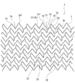
The stent may be a
The difference between the
In this
また、ステント60では、共有線状部21(第1パターン共有線状部)と共有線状部41(第2パターン共有線状部)は、ステントの軸方向に対して斜めに延びるとともに、両者の向きが異なるものとなっている。
具体的に説明すると、このステント60では、第1パターン共有線状部21の終端は、線状部24により、他端側屈曲部と連結する形態となっており、同様に、第2のパターン共有線状部41の終端も、線状部24により、他端側屈曲部と連結する形態となっている。つまり、上述したステント1では、線状部24は、軸方向に隣り合う2つの共有線状部(正確には、一方の共有線状部の終端と他方の線状共有部の始端)を連結していたのに対し、ステント60では、共有線状部同士を連結する形態とはなっていない。なお、共有線状部と連結する線状部24は、上述したステント1に比べて明確な長線状部となっていない。なお、この線状部24は、他の線状部より若干長い程度である。なお、この線状部24は、長線状部であってもよい。
In the
More specifically, in this
また、このステント60では、第1パターン共有線状部21に対して、ステントの軸方向に隣り合う第2パターン共有線状部41は、1つの一端側屈曲部と1つの他端側屈曲部分ずれた位置に設けられている。そして、ステントの軸方向に隣り合う2つの第1パターン共有線状部21および2つの第2パターン共有線状部41は、ステント60の中心軸に対してほぼ等角度に配置された状態となっている。このため、ステントは、全体においてほぼ均一の拡張力を発現可能である。
また、このステント60では、図13に示すように、ステントの軸方向に配置された13の波線状環状体を備えている。そして、第1パターン共有線状部21は、ステントの軸方向に対して、螺旋状となるように配置されたものとなっており、同様に、第2パターン共有線状部41も、ステントの軸方向に対して、螺旋状となるように配置されたものとなっている。具体的には、一つおきに隣り合う波線状環状体は、3つの第1パターン共有線状部21により連結されており、それぞれの第1パターン共有線状部21は、ステントの軸方向に螺旋状となるように配置されている。このため、第1パターン共有線状部21による3つの螺旋が形成されている。そして、一つの螺旋は、6つの第1パターン共有線状部21により構成される。同様に、一つおきに隣り合う波線状環状体(第1パターン共有線状部21により連結されていない)は、3つの第2パターン共有線状部41により連結されており、それぞれの第2パターン共有線状部41は、ステントの軸方向に螺旋状となるように配置されている。このため、第2パターン共有線状部41による3つの螺旋が形成されている。そして、一つの螺旋は、6つの第2パターン共有線状部41により構成されている。
In the
Further, as shown in FIG. 13, the
また、上述したように、第1パターン共有線状部21と第2パターン共有線状部41は、ステントの軸方向に対して斜めに延びるととともに、両者の向きが異なるものとなっており、特に、両者の向きは、ステントの中心軸に対して、ほぼ対称であることが好ましい。このようにすることにより、ステントは、全体においてほぼ均一の拡張力を発現可能である。
ステントの軸方向での並びで言うと、まず第1パターン共有線状部21が3つ円周方向に均等に存在し、次のステント軸方向では、第2パターン共有線状部41が3つ円周方向に均等に存在する。次のステント軸方向では、第2パターン共有線状部41が3つ円周方向に均等に存在する。
次のステント軸方向では、第1パターン共有線状部21が3つ円周方向に均等に存在する。繰り返すと、21、41,41,21、21、41,41・・・・・・という並び方をしているのが特徴である。
そして、この実施例のステント60は、上述したステント1と構造が異なることにより、軸方向の伸び縮みに対する抵抗力を小さいものとすることができ、血管の変形に対する追従性が良好なものとなる。
In addition, as described above, the first pattern shared
Speaking of the arrangement in the axial direction of the stent, first, three first pattern shared
In the next stent axial direction, three first pattern shared
The
また、ステントとしては、図15ないし17に示すようなパターンのステント70であってもよい。図15は、本発明のステントの他の実施例の正面図である
。図16は、図15に示したステントの展開図である。図17は、図15に示したステントを縮径させた状態のステントの展開図である。
このステント70と上述したステント1との相違は、共有線状部の配置形態およびその向きなどである。
このステント70では、1つの環状体2における一端側屈曲部および他端側屈曲部の数はステント1と同じ(具体的には、それぞれ9)であり、軸方向には、10の環状体が配置されたものとなっている。隣り合う2つの環状体2は、3つの共有線状部21(第1パターン共有線状部)もしくは3つの共有線状部41(第2パターン共有線状部)により一体化されている。そして、3つの共有線状部21は、ステントの中心軸に対して、ほぼ等角度に設けられている。同様に、3つの共有線状部41も、ステントの中心軸に対して、ほぼ等角度に設けられている。
The stent may be a
The difference between the
In this
このステント70では、共有線状部21(第1パターン共有線状部)と共有線状部41(第2パターン共有線状部)が、ステントの軸方向に対して交互となるように配置されており、かつ、共有線状部21(第1パターン共有線状部)と共有線状部41(第2パターン共有線状部)が、軸方向に連続しないように配置されている。具体的には、共有線状部41(第2パターン共有線状部)は、共有線状部21(第1パターン共有線状部)の配置位置に対して、ステントの外周方向にずれた位置に配置されている。また、共有線状部21(第1パターン共有線状部)同士は、ステントの軸方向に対してほぼ直線上に配置されている。同様に、共有線状部41(第2パターン共有線状部)同士も、ステントの軸方向に対してほぼ直線上に配置されている。
In this
また、ステント70では、共有線状部21(第1パターン共有線状部)と共有線状部41(第2パターン共有線状部)は、ステントの軸方向に対して斜めに延びるととともに、両者の向きが異なるものとなっている。
具体的に説明すると、このステント70では、第1パターン共有線状部21の終端は、線状部24により、他端側屈曲部と連結する形態となっており、同様に、第2のパターン共有線状部41の終端も、線状部24により、他端側屈曲部と連結する形態となっている。つまり、上述したステント1では、長線状部24は、軸方向に隣り合う2つの共有線状部(正確には、一方の共有線状部の終端と他方の線状共有部の始端)を連結していたのに対し、ステント70では、共有線状部同士を連結する形態とはなっていない。なお、共有線状部と連結する線状部24は、上述したステント1に比べて明確な長線状部となっていない。なお、この線状部24は、他の線状部より若干長い程度である。なお、この線状部24は、長線状部であってもよい。
In the
Specifically, in this
また、このステント70では、第1パターン共有線状部21に対して、ステントの軸方向に隣り合う第2パターン共有線状部41は、1つの一端側屈曲部と1つの他端側屈曲部分ずれた位置に設けられている。そして、ステントの軸方向に隣り合う2つの第1パターン共有線状部21および2つの第2パターン共有線状部41は、ステント70の中心軸に対してほぼ等角度に配置された状態となっている。このため、ステントは、全体においてほぼ均一の拡張力を発現可能である。
また、上述したように、第1パターン共有線状部21と第2パターン共有線状部41は、ステントの軸方向に対して斜めに延びるとともに、両者の向きが異なるものとなっており、特に、両者の向きは、ステントの中心軸に対して、ほぼ対称であることが好ましい。このようにすることにより、ステントは、全体においてほぼ、均一の拡張力を発現可能である。ステントの軸方向での並びで言うと、まず、1パターン共有線状部21が3つ円周方向に均等に存在し、次のステント軸方向では、第2パターン共有線状部41が3つ円周方向に均等に存在する。次のステント軸方向では、第1パターン共有線状部21が3つ円周方向に均等に存在する。
次のステント軸方向では、第2パターン共有線状部41が3つ円周方向に均等に存在する。繰り返すと、21、41,21,41、21、41,21・・・・・・という並び方をしているのが特徴である。
Further, in this
In addition, as described above, the first pattern shared
In the next stent axial direction, three second pattern shared
そして、この実施例のステント70は、上述したステント1と構造が異なることにより、軸方向の伸び縮みに対する抵抗力を小さいものとすることができ、血管の変形に対する追従性が良好なものとなる。
なお、この実施例のステント70では、図16に示すように、波線状環状体2は、第1パターン共有線状部21の終端23と一端側屈曲部の頂点2a間を連結する短線状部26を有している。そして、この波線状環状体と隣り合う波線状環状体は、第1パターン共有線状部21の始端22と他端側屈曲部の頂点間を連結する短線状部25と、第2パターン共有線状部41の終端42と一端側屈曲部の頂点間を連結する短線状部47を有している。
The
In addition, in the
また、ステントとしては、図18および図19に示すような、パターンのステント80であってもよい。図18は、本発明のステントの他の実施例の展開図である。図19は、図18に示したステントを縮径させた状態のステントの展開図である。
このステント80と上述したステント1との相違は、1つの波線状環状体2における一端側屈曲部および他端側屈曲部の数、隣り合う環状体を一体化する共有線状部の数、共有線状部の配置形態およびその向き、両端部に設けられたマーカー、両端部に位置する波状線体に設けられた連結部などである。
このステント80の形態は、上述したステント50と基本構成は同じである。
このステント80では、1つの環状体2における一端側屈曲部および他端側屈曲部の数はステント1より少ない(具体的には、それぞれ8)ものとなっており、軸方向には、11の環状体が配置されたものとなっており、隣り合う2つの環状体2、2つの共有線状部21(第1パターン共有線状部)もしくは2つの共有線状部41(第2パターン共有線状部)により一体化されている。そして、2つの共有線状部21は、ステントの中心軸に対して、向かい合う位置に設けられている。同様に、2つの共有線状部41も、ステントの中心軸に対して、向かい合う位置に設けられている。
Further, the stent may be a
The difference between the
The basic configuration of the
In this
このステント80では、第1パターン共有線状部21と第2パターン共有線状部41が、ステントの軸方向に対して交互となるように配置されており、かつ、第1パターン共有線状部21と第2パターン共有線状部41が、軸方向に連続しないように配置されている。具体的には、第2パターン共有線状部41は、第1パターン共有線状部21の配置位置に対して、ステントの外周方向にずれた位置に配置されている。
また、ステント80では、第1パターン共有線状部21と第2パターン共有線状部41は、ステントの軸方向に対して斜めに延びるととともに、両者の向きが異なるものとなっている。
このステント80では、第1パターン共有線状部21に対して、ステントの軸方向に隣り合う第2パターン共有線状部41は、1つの一端側屈曲部と1つの他端側屈曲部分ずれた位置に設けられている。そして、ステントの軸方向に隣り合う2つの第1パターン共有線状部21および2つの第2パターン共有線状部41は、ステント80の中心軸に対してほぼ等角度に配置された状態となっている。このため、ステントは、全体においてほぼ均一の拡張力を発現可能である。
In this
In the
In this
また、このステント80では、図18に示すように、第1パターン共有線状部21は、ステントの軸方向に対して、螺旋状となるように配置されたものとなっており、同様に、第2パターン共有線状部41も、ステントの軸方向に対して、螺旋状となるように配置されたものとなっている。
また、このステント80では、図18に示すように、ステントの軸方向に配置された11の波線状環状体を備えている。そして、第1パターン共有線状部21は、ステントの軸方向に対して、螺旋状となるように配置されたものとなっており、同様に、第2パターン共有線状部41も、ステントの軸方向に対して、螺旋状となるように配置されたものとなっている。具体的には、一つおきに隣り合う波線状環状体は、2つの第1パターン共有線状部21より連結されており、それぞれの第1パターン共有線状部21は、ステントの軸方向に螺旋状となるように配置されている。このため、第1パターン共有線状部21による2つの螺旋が形成されている。そして、一つの螺旋は、5つの第1パターン共有線状部21により構成される。また、同様に、一つおきに隣り合う波線状環状体(第1パターン共有線状部21により連結されていない)は、2つの第2パターン共有線状部41により連結されており、それぞれの第2パターン共有線状部41は、ステントの軸方向に螺旋状となるように配置されている。このため、第2パターン共有線状部41による2つの螺旋が形成されている。そして、一つの螺旋は、5つの第2パターン共有線状部41により構成されている。
Further, in this
In addition, as shown in FIG. 18, the
また、上述したように、第1パターン共有線状部21と第2パターン共有線状部41は、ステントの軸方向に対して斜めに延びるとともに、両者の向きが異なるものとなっており、特に、両者の向きは、ステントの中心軸に対して、ほぼ対称であることが好ましい。このようにすることにより、ステントは、全体においてほぼ均一の拡張力を発現可能である。
なお、この実施例のステント80では、図18に示すように、波線状環状体2は、第1パターン共有線状部21の終端23と一端側屈曲部の頂点2a間を連結する短線状部26を有している。そして、この波線状環状体と隣り合う波線状環状体は、第1パターン共有線状部21の始端22と他端側屈曲部の頂点2b間を連結する短線状部25と、第2パターン共有線状部41の終端42と一端側屈曲部の頂点間を連結する短線状部47を有している。
In addition, as described above, the first pattern shared
In addition, in the
このステント80では、図18および図19に示すように、造影用マーカー11が設けられている。造影用マーカー11は、ステントの端部に設けることが好ましい。特に、両端部にそれぞれ設けることが好ましい。具体的には、図18および図19に示すように、両端部にそれぞれ複数のマーカー11を設けることが好ましい。この実施例のステント80では、ステントの端部に位置する頂点部に形成された開口部27を有し、この開口部27を閉塞するようにマーカー11が固定されている。造影マーカーとしては、ステント10において説明したものと同じである。
そして、開口部27の外側端は、図18および図19に示すように、ステントの端部に位置する他の頂点部の外側端と同じ位置となっている。つまり、このステント80では、マーカーが設けられる開口部27の外側端は、ステントの端部に位置する他の頂点部の外側端より突出していない。ステントの端部の位置を揃えることにより、ステントが曲がった状態でも確実に、ステントを押し出すことができる。
また、ステントは、マーカー配置部位より、ステントの中央方向に延びかつ離間する2本の脚部を有している。図19に示すように収縮状態(マウント時)において、これら2本の脚部は、離間しかつ近接する線状部とほぼ平行となっている。
具体的には、このステント80では、マーカーが配置される開口部27を有する屈曲部における開口部27より延びる2本の脚部は、開口部27のステントの内側部位でありかつ所定距離離間した2つの位置を始端として、ステントの内側方向に延びるものとなっている。開口部27より延びる2本の脚部は、離間したものとなっている。つまり、このステント80では、開口部27より延びる脚部は、図5に示したステント10のように近接していない。このように、開口部27より延びる2本の脚部を離間させることにより、マーカー形成部(開口部27)付近の形状が安定する。このため、マーカー形成部(開口部27)付近に強い力(ステント押出時)が負荷されても、ステントの変形がない。このため、ステントを確実に押し出すことができる。
In this
And the outer side edge of the
In addition, the stent has two legs that extend from the marker placement site toward the center of the stent and are spaced apart. As shown in FIG. 19, in the contracted state (when mounted), these two leg portions are substantially parallel to the linear portions that are separated and close to each other.
Specifically, in this
さらに、このステント80では、図18および図19に示すように、両端に位置する波線状環状体2には、この波状環状体2と隣り合う波線状環状体2とを連結する連結部81が設けられている。ステント80では、両端に位置する波線状環状体2とこれと隣り合う波線状環状体2間には、2本の連結部81が設けられている。なお、ステント80では、両端部に位置する2つの波線状環状体間にのみ連結部81が設けられている。そして、2本の連結部81は、ステントの中心軸に対して、向かい合う位置に設けられている。そして、図18および図19に示すように、ステント80の一端部(上端部)では、上述した2つの共有線状部21および上述した2本の連結部81が、ステントの中心軸に対して、ほぼ等角度となるように配置されている。同様に、ステント80の他端部(下端部)では、上述した2つの共有線状部41および上述した2本の連結部81が、ステントの中心軸に対して、ほぼ等角度となるように配置されている。
このようにステント80では、ステントの両端部に共有線状部とともに連結部を有するため、ステントの拡張後における両端部の形態安定性が良好なものとなる。なお、上述した実施例のステント80では、ステントの両端部に2つの連結部を有するが、これに限定されるものではなく、1つもしくは3つであってもよい。
そして、この実施例のステント80は、上述したステント1と構造が異なることにより、軸方向の伸び縮みに対する抵抗力を小さいものとすることができ、血管の変形に対する追従性が良好なものとなる。
Furthermore, in this
As described above, since the
The
また、ステントとしては、図20および図21に示すような、パターンのステント90であってもよい。図20は、本発明のステントの他の実施例の展開図である。図21は、図20に示したステントを縮径させた状態のステントの展開図である。
このステント90と上述したステント1との相違は、1つの波線状環状体2における一端側屈曲部および他端側屈曲部の数、隣り合う環状体を一体化する共有線状部の数、共有線状部の配置形態およびその向き、両端部に設けられたマーカーなどである。
このステント90の形態は、上述したステント50と似ている。
このステント90では、1つの環状体2における一端側屈曲部および他端側屈曲部の数はステント1より少ない(具体的には、それぞれ8)ものとなっており、軸方向には、21個の環状体が配置されたものとなっている。ステント90では、隣り合う2つの環状体2、共有線状部91(第1パターン共有線状部)もしくは共有線状部92(第2パターン共有線状部)により一体化されている。そして、ステント90では、隣り合う2つの環状体2は、少なくとも2つの共有線状部により一体化されている。そして、2つの共有線状部91は、ステントの中心軸に対して、向かい合う位置に設けられている。同様に、2つの共有線状部92も、ステントの中心軸に対して、向かい合う位置に設けられている。
Further, as the stent, a
The difference between the
The form of the
In this
なお、このステント90では、図20および図21に示すように、両端に位置する波線状環状体2と隣り合う波線状環状体2とは、4つの共有線状部により一体化されている。そして、ステント90の一端部(上端部)では、上述した4つの共有線状部91が、ステントの中心軸に対して、ほぼ等角度となるように配置されている。同様に、ステント90の他端部(下端部)では、上述した4つの共有線状部92が、ステントの中心軸に対して、ほぼ等角度となるように配置されている。
このようにステント90では、ステントの両端部にのみ、他の部分より多くの共有線状部を有するため、ステントの拡張後における両端部の形態安定性が良好なものとなる。
そして、このステント90では、第1パターン共有線状部91と第2パターン共有線状部92が、ステントの軸方向に対して交互となるように配置されており、かつ、第1パターン共有線状部91と第2パターン共有線状部92が、軸方向に連続しないように配置されている。具体的には、第2パターン共有線状部92は、第1パターン共有線状部91の配置位置に対して、ステントの外周方向にずれた位置に配置されている。
In this
Thus, since the
In the
また、ステント90では、第1パターン共有線状部91と第2パターン共有線状部92は、ステントの軸方向に対して斜めに延びるととともに、両者の向きが異なるものとなっている。
また、このステント90では、ステント90の両端部を除き、第1パターン共有線状部91に対して、ステントの軸方向に隣り合う第2パターン共有線状部92は、1つの一端側屈曲部と1つの他端側屈曲部分ずれた位置に設けられている。そして、ステントの軸方向に隣り合う2つの第1パターン共有線状部91および2つの第2パターン共有線状部92は、ステント90の中心軸に対してほぼ等角度に配置された状態となっている。このため、ステントは、全体においてほぼ均一の拡張力を発現可能である。
また、このステント90では、図20に示すように、第1パターン共有線状部91は、ステントの軸方向に対して、螺旋状となるように配置されたものとなっており、同様に、第2パターン共有線状部92も、ステントの軸方向に対して、螺旋状となるように配置されたものとなっている。
In the
Further, in this
Further, in this
また、このステント90では、図20に示すように、ステントの軸方向に配置された21個の波線状環状体を備えている。そして、第1パターン共有線状部91は、ステントの軸方向に対して、螺旋状となるように配置されたものとなっており、同様に、第2パターン共有線状部92も、ステントの軸方向に対して、螺旋状となるように配置されたものとなっている。具体的には、一つおきに隣り合う波線状環状体は、2つの第1パターン共有線状部91より連結されており、それぞれの第1パターン共有線状部91は、ステントの軸方向に螺旋状となるように配置されている。このため、第1パターン共有線状部91による2つの螺旋が形成されている。また、同様に、一つおきに隣り合う波線状環状体(第1パターン共有線状部91により連結されていない)は、2つの第2パターン共有線状部92により連結されており、それぞれの第2パターン共有線状部92は、ステントの軸方向に螺旋状となるように配置されている。このため、第2パターン共有線状部92による2つの螺旋が形成されている。
また、上述したように、第1パターン共有線状部91と第2パターン共有線状部92は、ステントの軸方向に対して斜めに延びるとともに、両者の向きが異なるものとなっており、特に、両者の向きは、ステントの中心軸に対して、ほぼ対称であることが好ましい。このようにすることにより、ステントは、全体においてほぼ均一の拡張力を発現可能である。
Further, as shown in FIG. 20, the
In addition, as described above, the first pattern shared
なお、この実施例のステント90では、図20に示すように、波線状環状体2は、第1パターン共有線状部91の終端23と一端側屈曲部の頂点2a間を連結する短線状部26を有している。そして、この波線状環状体と隣り合う波線状環状体は、第1パターン共有線状部91の始端22と他端側屈曲部の頂点2b間を連結する短線状部25と、第2パターン共有線状部92の終端42と一端側屈曲部の頂点間を連結する短線状部を有している。
このステント90では、図20および図21に示すように、造影用マーカー11が設けられている。造影用マーカー11は、ステントの端部に設けることが好ましい。特に、両端部にそれぞれ設けることが好ましい。具体的には、図20および図21に示すように、両端部にそれぞれ複数のマーカー11を設けることが好ましい。この実施例のステント90では、ステントの端部に位置する頂点部に形成された開口部27を有し、この開口部27を閉塞するようにマーカー11が固定されている。造影マーカーとしては、ステント10において説明したものと同じである。
In addition, in the
In this
そして、開口部27の外側端は、図20および図21に示すように、ステントの端部に位置する他の頂点部の外側端と同じ位置となっている。つまり、このステント90では、マーカーが設けられる開口部27の外側端は、ステントの端部に位置する他の頂点部の外側端より突出していない。ステントの端部の位置を揃えることにより、ステントが曲がった状態でも確実に、ステントを押し出すことができる。さらに、このステント90では、開口部27を有する屈曲部における開口部27より延びる2本の脚部は、開口部27のステントの内側部位でありかつ所定距離離間した2つの位置を始端として、ステントの内側方向に延びるものとなっている。開口部27より延びる2本の脚部は、離間したものとなっている。つまり、このステント90では、開口部27より延びる脚部は、図5に示したステント10のように近接していない。このように、開口部27より延びる2本の脚部を離間させることにより、マーカー形成部(開口部27)付近の形状が安定する。このため、マーカー形成部(開口部27)付近に強い力(ステント押出時)が負荷されても、ステントの変形がない。このため、ステントを確実に押し出すことができる。
And the outer side end of the
そして、ステントは、留置対象部位により異なるが、一般的に、拡張時(非縮径時、復元時)の外径が2.0〜30mm、好ましくは2.5〜20mm、肉厚が0.04〜1.0mm、好ましくは0.06〜0.5mmのものであり、長さは、10〜150mm、より好ましくは15〜100mmである。特に、血管内留置用ステントの場合には、外径が2.0〜14mm、好ましくは2.5〜12mm、肉厚が0.04〜0.3mm、好ましくは0.06〜0.22mmのものであり、長さは5〜100mm、より好ましくは10〜80mmである。
そして、ステントは、生体内挿入前および生体内挿入後のいずれにおいても超弾性を示す超弾性金属により略円筒形状に一体に形成されている。
And although a stent changes with indwelling object site | parts, generally the outer diameter at the time of expansion (at the time of a non-contraction diameter, at the time of decompression | restoration) is 2.0-30 mm, Preferably 2.5-20 mm, Wall thickness is 0. The length is 04 to 1.0 mm, preferably 0.06 to 0.5 mm, and the length is 10 to 150 mm, more preferably 15 to 100 mm. In particular, in the case of an intravascular stent, the outer diameter is 2.0 to 14 mm, preferably 2.5 to 12 mm, and the wall thickness is 0.04 to 0.3 mm, preferably 0.06 to 0.22 mm. The length is 5 to 100 mm, more preferably 10 to 80 mm.
The stent is integrally formed in a substantially cylindrical shape with a superelastic metal exhibiting superelasticity before and after insertion into the living body.
超弾性金属としては、超弾性合金が好適に使用される。ここでいう超弾性合金とは一般に形状記憶合金といわれ、少なくとも生体温度(37℃付近)で超弾性を示すものである。特に好ましくは、49〜54原子%NiのTiNi合金、38.5〜41.5重量%ZnのCu−Zn合金、1〜10重量%XのCu−Zn−X合金(X=Be,Si,Sn,Al,Ga)、36〜38原子%AlのNi−Al合金等の超弾性金属体が好適に使用される。特に好ましくは、上記のTiNi合金である。また、Ti−Ni合金の一部を0.01〜10.0%Xで置換したTi−Ni−X合金(X=Co,Fe,Mn,Cr,V,Al,Nb,W,B、Au,Pdなど)とすること、またはTi−Ni合金の一部を0.01〜30.0%原子で置換したTi−Ni−X合金(X=Cu,Pb,Zr)とすること、また、冷間加工率または/および最終熱処理の条件を選択することにより、機械的特性を適宜変えることができる。 As the superelastic metal, a superelastic alloy is preferably used. The superelastic alloy here is generally called a shape memory alloy, and exhibits superelasticity at least at a living body temperature (around 37 ° C.). Particularly preferably, a TiNi alloy of 49 to 54 atomic% Ni, a Cu—Zn alloy of 38.5 to 41.5 wt% Zn, and a Cu—Zn—X alloy of 1 to 10 wt% X (X = Be, Si, Sn, Al, Ga), a super elastic metal body such as a 36-38 atomic% Al Ni-Al alloy is preferably used. The TiNi alloy is particularly preferable. Further, a Ti—Ni—X alloy (X = Co, Fe, Mn, Cr, V, Al, Nb, W, B, Au, in which a part of the Ti—Ni alloy is substituted with 0.01 to 10.0% X. , Pd, etc.), or a Ti—Ni—X alloy (X = Cu, Pb, Zr) in which a part of the Ti—Ni alloy is substituted with 0.01 to 30.0% atoms, By selecting the cold working rate or / and the final heat treatment conditions, the mechanical properties can be appropriately changed.
また、上記のTi−Ni−X合金を用いて冷間加工率および/または最終熱処理の条件を選択することにより、機械的特性を適宜変えることができる。そして、使用される超弾性合金の座屈強度(負荷時の降伏応力)は、5〜200kg/mm2(22℃)、より好ましくは、8〜150kg/mm2、復元応力(除荷時の降伏応力)は、3〜180kg/mm2(22℃)、より好ましくは、5〜130kg/mm2である。ここでいう超弾性とは、使用温度において通常の金属が塑性変形する領域まで変形(曲げ、引張り、圧縮)させても、荷重の解放後、加熱を必要とせずにほぼ元の形状に回復することを意味する。
そして、ステントは、例えば、超弾性金属パイプを用いて、ステント非構成部分を除去(例えば、切削、溶解)することにより作製され、これにより、一体形成物となっている。なお、本発明のステントの形成に用いられる超弾性金属パイプは、不活性ガスまたは真空雰囲気にて溶解しTi−Ni合金などの超弾性合金のインゴットを形成し、このインゴットを機械的に研磨し、続いて、熱間プレスおよび押し出しにより、太径パイプを形成し、その後順次ダイス引き抜き工程および熱処理工程を繰り返すことにより、所定の肉厚、外径のパイプに細径化し、最終的に表面を化学的または物理的に研磨することにより製造することができる。そして、この超弾性金属パイプによるステント基材の形成は、切削加工(例えば、機械研磨、レーザー切削加工)、放電加工、化学エッチングなどにより行うことができ、さらにそれらの併用により行ってもよい。
Further, the mechanical characteristics can be appropriately changed by selecting the cold work rate and / or the final heat treatment conditions using the Ti—Ni—X alloy. And the buckling strength (the yield stress at the time of loading) of the superelastic alloy used is 5 to 200 kg / mm 2 (22 ° C.), more preferably 8 to 150 kg / mm 2 , and the restoring stress (at the time of unloading). The yield stress is 3 to 180 kg / mm 2 (22 ° C.), more preferably 5 to 130 kg / mm 2 . Superelasticity here means that even if it is deformed (bending, pulling, compressing) to the region where ordinary metal plastically deforms at the operating temperature, it will recover to its original shape without requiring heating after releasing the load. Means that.
Then, the stent, for example, using a super-elastic metal pipe, removing the stent non components (e.g., cutting, dissolving) more was fabricated to thereby, are integrated formation. The superelastic metal pipe used for forming the stent of the present invention is melted in an inert gas or vacuum atmosphere to form a superelastic alloy ingot such as a Ti-Ni alloy, and this ingot is mechanically polished. Subsequently, a thick pipe is formed by hot pressing and extrusion, and then a die drawing process and a heat treatment process are sequentially repeated to reduce the diameter of the pipe to a predetermined wall thickness and outer diameter, and finally the surface. It can be produced by chemical or physical polishing. And formation of the stent base material by this superelastic metal pipe can be performed by cutting (for example, mechanical polishing, laser cutting), electric discharge machining, chemical etching, or the like, and may be performed by using them together.
また、本発明のステントは、内面または外面、さらには両面に生体適合性材料を被覆してもよい。生体適合性材料としては、生体適合性を有する合成樹脂または金属が考えられる。ステントの表面を不活性な金属で被覆する方法としては、電気メッキ法を用いた金メッキ、蒸着法を用いたステンレスメッキ、スパッタ法を用いたシリコンカーバイド、ダイヤモンドライクカーボン、窒化チタンメッキ、金メッキなどが考えられる。また、合成樹脂としては、熱可塑系または熱硬化系の樹脂から選択できるが、例えば、ポリオレフィン(例えば、ポリエチレン、ポリプロピレン、エチレン−プロピレン共重合体など)、ポリ塩化ビニル、エチレン−酢酸ビニル共重合体、ポリアミドエラストマー、ポリウレタン、ポリエステル、フッ素樹脂、シリコーン樹脂等が使用でき、好ましくは、ポリオレフィン、ポリアミドエラストマー、ポリエステルあるいはポリウレタン、シリコーン樹脂、また、生体内分解性樹脂(例えば、ポリ乳酸、ポリグリコール酸、両者のコポリマー)である。合成樹脂被膜は、ステントを構成するフレームの湾曲の妨げにならない程度に柔軟であることが好ましい。合成樹脂被膜の肉厚は、3〜300μm、好ましくは、5〜100μmである。 In addition, the stent of the present invention may be coated with a biocompatible material on the inner surface or outer surface, and further on both surfaces. The biocompatible material may be a synthetic resin or metal having biocompatibility. Methods for coating the stent surface with an inert metal include gold plating using electroplating, stainless steel plating using vapor deposition, silicon carbide using sputtering, diamond-like carbon, titanium nitride plating, and gold plating. Conceivable. The synthetic resin can be selected from thermoplastic or thermosetting resins. For example, polyolefin (for example, polyethylene, polypropylene, ethylene-propylene copolymer, etc.), polyvinyl chloride, ethylene-vinyl acetate copolymer. Polymers, polyamide elastomers, polyurethanes, polyesters, fluororesins, silicone resins, etc. can be used, preferably polyolefins, polyamide elastomers, polyesters or polyurethanes, silicone resins, and biodegradable resins (for example, polylactic acid, polyglycolic acid) , A copolymer of both). The synthetic resin coating is preferably flexible to the extent that it does not hinder the bending of the frame constituting the stent. The thickness of the synthetic resin coating is 3 to 300 μm, preferably 5 to 100 μm.
ステントの表面に合成樹脂を薄く被覆する方法としては、例えば、溶融状態または溶液状態の合成樹脂の中に、ステントを挿入して被覆する方法、モノマーを超弾性金属パイプの表面で重合させながら被覆する化学蒸着などがある。極薄な樹脂被覆が要求される場合は、希薄溶液を用いた被覆、または化学蒸着が好適である。さらに、より生体適合性材料を向上させるために、上記樹脂被膜に抗血栓性材料を被覆または固定してもよい。抗血栓性材料として、公知の各種の樹脂を単独または混合して使用することができるが、例えば、ポリヒドロキシエチルメタアクリレート、ヒドロキシエチルメタアクリレートとスチレンの共重合体(例えば、HEMA−St−HEMAブロック共重合体)などが好適に使用できる。 As a method of thinly coating the surface of the stent with a synthetic resin, for example, a method in which a stent is inserted into a synthetic resin in a molten state or a solution state, and coating is performed while a monomer is polymerized on the surface of a superelastic metal pipe. Chemical vapor deposition. When an extremely thin resin coating is required, coating using a dilute solution or chemical vapor deposition is preferable. Furthermore, in order to improve the biocompatible material, an antithrombotic material may be coated or fixed on the resin coating. As the antithrombogenic material, various known resins can be used alone or in combination. For example, polyhydroxyethyl methacrylate, a copolymer of hydroxyethyl methacrylate and styrene (for example, HEMA-St-HEMA) Block copolymers) can be used preferably.
また、上述したすべての実施例におけるステントは、略管状体に形成され、生体内管腔への挿入のための直径を有し、該管状体の内部より半径方向に広がる力が付加されたときに拡張可能なステント、いわゆるバルーン拡張型ステントであってもよい。
バルーン拡張型ステントの形成材料としては、ある程度の生体適合性を有するものが好ましく、例えば、ステンレス鋼、タンタルもしくはタンタル合金、プラチナもしくはプラチナ合金、金もしくは金合金、コバルトベース合金、コバルトクロム合金、チタン合金、ニオブ合金等が考えられる。
またステント形状を作製した後に貴金属メッキ(金、プラチナ)をしてもよい。ステンレス鋼としては、最も耐腐食性のあるSUS316Lが好適である。
In addition, the stents in all the embodiments described above are formed in a substantially tubular body, have a diameter for insertion into a living body lumen, and are subjected to a force that expands radially from the inside of the tubular body. It is also possible to use a so-called balloon expandable stent.
As a material for forming the balloon expandable stent, a material having a certain degree of biocompatibility is preferable. For example, stainless steel, tantalum or tantalum alloy, platinum or platinum alloy, gold or gold alloy, cobalt base alloy, cobalt chromium alloy, titanium An alloy, a niobium alloy, etc. can be considered.
Moreover, after producing the stent shape, precious metal plating (gold, platinum) may be performed. As stainless steel, SUS316L having the most corrosion resistance is suitable.
さらに、ステントの最終形状を作製したのち、焼なましすることが好ましい。焼きなましを行うことにより、ステント全体の柔軟性および可塑性が向上し、屈曲した血管内での留置性が良好となる。焼きなましを行わない場合に比べて、ステントを拡張した後の拡張前形状に復元しようとする力、特に、屈曲した血管部位で拡張したときに発現する直線状に復帰しようとする力が減少し、屈曲した血管内壁に与える物理的な刺激が減少し、再狭窄の要因を減少させることができる。焼きなましは、ステント表面に酸化被膜が形成されないように、不活性ガス雰囲気下(例えば、窒素と水素の混合ガス)にて、900〜1200℃に加熱したのち、ゆっくりと冷却することにより行うことが好ましい。
また、ステントの非拡張時の直径は、0.8〜1.8mm程度が好適であり、特に、0.9〜1.6mmがより好ましい。また、ステントの非拡張時の長さは、8〜40mm程度が好適である。また、一つの波線状環状体2の長さは、8〜25mm程度が好適である。
そして、ステントの成形は、管状体(具体的には、金属パイプ)よりフレーム構造体となる部分以外を除去することにより行われる。具体的には、金属パイプを、例えば、フォトファブリケーションと呼ばれるマスキングと化学薬品を使用したエッチング方法、切削加工(例えば、機械研磨、レーザー切削加工)、放電加工などにより行うことができ、さらにそれらの併用により行ってもよい。
Furthermore, it is preferable to anneal after producing the final shape of the stent. By performing the annealing, the flexibility and plasticity of the entire stent are improved, and the indwellability in the bent blood vessel is improved. Compared to the case where annealing is not performed, the force to restore the shape before expansion after expanding the stent, particularly the force to return to the linear shape that appears when expanding at a bent blood vessel site, The physical stimulation applied to the bent inner wall of the blood vessel is reduced, and the factor of restenosis can be reduced. Annealing is performed by heating to 900 to 1200 ° C. in an inert gas atmosphere (for example, a mixed gas of nitrogen and hydrogen) and then slowly cooling so that an oxide film is not formed on the stent surface. preferable.
The diameter of the stent when not expanded is preferably about 0.8 to 1.8 mm, more preferably 0.9 to 1.6 mm. The length of the stent when not expanded is preferably about 8 to 40 mm. Further, the length of one wavy
Then, the stent is formed by removing the portion other than the portion that becomes the frame structure from the tubular body (specifically, the metal pipe). Specifically, a metal pipe can be formed by, for example, a masking method called photofabrication and an etching method using chemicals, cutting (for example, mechanical polishing, laser cutting), electric discharge machining, and the like. You may carry out by combined use.
また、上述したすべての実施例において、図5に示すステント10のように、造影用マーカー11を設けることが好ましい。造影用マーカー11は、ステントの端部側に設けることが好ましい。特に、両端部側にそれぞれ設けることが好ましい。具体的には、図5に示すように、両端側にそれぞれ複数のマーカー11を設けることが好ましい。マーカーについては、上述した通りである。
In all the embodiments described above, it is preferable to provide a
次に、本発明のステントの具体的実施例について述べる。
(実施例1)
TiNi合金(51原子%Ni)の合金パイプを冷間加工して、外径約1.9mm、肉厚0.25mm、長さ約100mmの超弾性金属パイプを作製した。そして、金属パイプを軸がぶれないようにファスナー機構の付いた回転モーター付治具にセットし、さらにこれを数値制御可能なXテーブル上にセットした。そして、Xテーブルおよび回転モーターをパーソナルコンピュータに接続し、パーソナルコンピュータの出力が、Xテーブルの数値制御コントローラーおよび回転モーターに入力されるものとした。パーソナルコンピュータ内には図面ソフトが記憶されており、ここに図3に示すような構図のステントの展開図面を入力した。このような構成により、パーソナルコンピュータより出力される図面データに基づいて、Xテーブルおよび回転モーターが駆動する。
このようにして金属パイプにレーザーを照射することにより、図3のような展開図を有する形状のステント基材を作製した。
上記金属パイプのレーザー加工条件としては、平均出力5.5W、駆動スピード180mm/分にて行った。そして、上記のステント基材に内面研削加工を行った。
Next, specific examples of the stent of the present invention will be described.
Example 1
A TiNi alloy (51 atomic% Ni) alloy pipe was cold worked to produce a superelastic metal pipe having an outer diameter of about 1.9 mm, a wall thickness of 0.25 mm, and a length of about 100 mm. Then, the metal pipe was set in a jig with a rotary motor with a fastener mechanism so as not to shake the shaft, and further set on an X table capable of numerical control. The X table and the rotary motor were connected to a personal computer, and the output of the personal computer was input to the numerical control controller and the rotary motor of the X table. Drawing software is stored in the personal computer, and a developed drawing of the stent having the composition as shown in FIG. 3 is input here. With such a configuration, the X table and the rotary motor are driven based on the drawing data output from the personal computer.
By irradiating the metal pipe with the laser in this way, a stent base material having a developed view as shown in FIG. 3 was produced.
The laser processing conditions for the metal pipe were an average output of 5.5 W and a driving speed of 180 mm / min. And the inner surface grinding process was performed to said stent base material.
次に、ステント基材内腔に、ステント基材内腔よりやや太い直径の芯金を挿入することによりステント基材を拡径し、芯金を挿入したままステント基材を熱処理して拡径した形状を記憶させた。この拡径熱処理工程により、ステント基材は元の直径よりやや太い(元の直径+1mm前後)形状に成形される。なお、芯金の材質は例えばステンレス等の金属が適当であり、熱処理温度は450℃〜550℃、時間は2分〜30分程度が好適である。続いて、さらにやや太い(拡径後の直径+2mm前後)芯金をステント基材内腔に挿入して拡径し、熱処理を施す。このようにして、ステント基材が目的とする外径に達するまで拡径熱処理を繰り返すことにより、図1に示すようなステント基材を作製する。なお、一つの熱処理工程を経る毎に、必要に応じて化学研磨工程を施しても良い。
目的とする形状に成形したステント基材は、このあと適宜、ブラスト処理、化学研磨工程と電解研磨工程を経て、表面を平滑にし、かつ金属光沢を付与する工程を施した。
このようにして作製したステントは、外径約8mm、全長約45mm、肉厚約0.2mm、各環状体における線状部の幅約0.11mm、環状体の軸方向の長さ約3mm、共有線状部の長さ約1.6mm、長線状部の長さ約3.4mmであった。
このステントは、十分な拡張力を有するとともに、接続部に歪みの集中が生じにくいものであった。
Next, the diameter of the stent substrate is expanded by inserting a core metal having a diameter slightly larger than that of the stent substrate lumen into the stent substrate lumen, and the stent substrate is heat treated while the core metal is inserted to expand the diameter. The shape was memorized. By this diameter expansion heat treatment step, the stent base material is formed into a shape slightly thicker than the original diameter (original diameter is around +1 mm). For example, a metal such as stainless steel is suitable for the material of the metal core, and the heat treatment temperature is preferably 450 ° C. to 550 ° C., and the time is preferably about 2 minutes to 30 minutes. Subsequently, a slightly thicker core (diameter after diameter expansion + around 2 mm) is inserted into the stent substrate lumen to expand the diameter, and heat treatment is performed. Thus, the stent base material as shown in FIG. 1 is produced by repeating the diameter expansion heat treatment until the stent base material reaches the target outer diameter. In addition, you may perform a chemical polishing process as needed whenever it passes through one heat processing process.
The stent base material molded into the target shape was appropriately subjected to a blasting process, a chemical polishing process, and an electrolytic polishing process, followed by a process of smoothing the surface and imparting a metallic luster.
The stent thus produced has an outer diameter of about 8 mm, a total length of about 45 mm, a wall thickness of about 0.2 mm, a width of a linear portion in each annular body of about 0.11 mm, an axial length of the annular body of about 3 mm, The length of the shared linear portion was about 1.6 mm, and the length of the long linear portion was about 3.4 mm.
This stent has a sufficient expansion force and is less likely to cause strain concentration at the connection portion.
(実施例2)
TiNi合金(51原子%Ni)の合金パイプを冷間加工して、外径約1.9mm、肉厚0.25mm、長さ約100mmの超弾性金属パイプを作製した。そして、金属パイプを軸がぶれないようにファスナー機構の付いた回転モーター付治具にセットし、さらにこれを数値制御可能なXテーブル上にセットした。そして、Xテーブルおよび回転モーターをパーソナルコンピュータに接続し、パーソナルコンピュータの出力が、Xテーブルの数値制御コントローラーおよび回転モーターに入力されるものとした。パーソナルコンピュータ内には図面ソフトが記憶されており、ここに図11に示すような構図のステントの展開図面を入力した。このような構成により、パーソナルコンピュータより出力される図面データに基づいて、Xテーブルおよび回転モーターが駆動する。
このようにして金属パイプにレーザーを照射することにより、図11のような展開図を有する形状のステント基材を作製した。
上記金属パイプのレーザー加工条件としては、平均出力5.5W、駆動スピード180mm/分にて行った。そして、上記のステント基材に内面研削加工を行った。
(Example 2)
A TiNi alloy (51 atomic% Ni) alloy pipe was cold worked to produce a superelastic metal pipe having an outer diameter of about 1.9 mm, a wall thickness of 0.25 mm, and a length of about 100 mm. Then, the metal pipe was set in a jig with a rotary motor with a fastener mechanism so as not to shake the shaft, and further set on an X table capable of numerical control. The X table and the rotary motor were connected to a personal computer, and the output of the personal computer was input to the numerical control controller and the rotary motor of the X table. Drawing software is stored in the personal computer, and an expanded drawing of a stent having a composition as shown in FIG. 11 is input here. With such a configuration, the X table and the rotary motor are driven based on the drawing data output from the personal computer.
By irradiating the metal pipe with the laser in this way, a stent base material having a developed view as shown in FIG. 11 was produced.
The laser processing conditions for the metal pipe were an average output of 5.5 W and a driving speed of 180 mm / min. And the inner surface grinding process was performed to said stent base material.
次に、ステント基材内腔に、ステント基材内腔よりやや太い直径の芯金を挿入することによりステント基材を拡径し、芯金を挿入したままステント基材を熱処理して拡径した形状を記憶させた。この拡径熱処理工程により、ステント基材は元の直径よりやや太い(元の直径+1mm前後)形状に成形される。なお、芯金の材質は例えばステンレス等の金属が適当であり、熱処理温度は450℃〜550℃、時間は2分〜30分程度が好適である。続いて、さらにやや太い(拡径後の直径+2mm前後)芯金をステント基材内腔に挿入して拡径し、熱処理を施す。このようにして、ステント基材が目的とする外径に達するまで拡径熱処理を繰り返すことにより、図9に示すようなステント基材を作製する。なお、一つの熱処理工程を経る毎に、必要に応じて化学研磨工程を施しても良い。
目的とする形状に成形したステント基材は、このあと適宜、ブラスト処理、化学研磨工程と電解研磨工程を経て、表面を平滑にし、かつ金属光沢を付与する工程を施した。
このようにして作製したステントは、外径約8mm、全長約45mm、肉厚約0.2mm、各環状体における線状部の幅約0.11mm、環状体の軸方向の長さ約3mm、共有線状部の長さ約1.6mmであった。
このステントは、十分な拡張力を有するとともに、接続部に歪みの集中が生じにくいものであった。
Next, the diameter of the stent substrate is expanded by inserting a core metal having a diameter slightly larger than that of the stent substrate lumen into the stent substrate lumen, and the stent substrate is heat treated while the core metal is inserted to expand the diameter. The shape was memorized. By this diameter expansion heat treatment step, the stent base material is formed into a shape slightly thicker than the original diameter (original diameter is around +1 mm). For example, a metal such as stainless steel is suitable for the material of the metal core, and the heat treatment temperature is preferably 450 ° C. to 550 ° C., and the time is preferably about 2 minutes to 30 minutes. Subsequently, a slightly thicker core (diameter after diameter expansion + around 2 mm) is inserted into the stent substrate lumen to expand the diameter, and heat treatment is performed. In this manner, the stent base material as shown in FIG. 9 is manufactured by repeating the diameter expansion heat treatment until the stent base material reaches the target outer diameter. In addition, you may perform a chemical polishing process as needed whenever it passes through one heat processing process.
The stent base material molded into the target shape was appropriately subjected to a blasting process, a chemical polishing process, and an electrolytic polishing process, followed by a process of smoothing the surface and imparting a metallic luster.
The stent thus produced has an outer diameter of about 8 mm, a total length of about 45 mm, a wall thickness of about 0.2 mm, a width of a linear portion in each annular body of about 0.11 mm, an axial length of the annular body of about 3 mm, The length of the shared linear portion was about 1.6 mm.
This stent has a sufficient expansion force and is less likely to cause strain concentration at the connection portion.
(実施例3)
TiNi合金(51原子%Ni)の合金パイプを冷間加工して、外径約1.9mm、肉厚0.25mm、長さ約100mmの超弾性金属パイプを作製した。そして、金属パイプを軸がぶれないようにファスナー機構の付いた回転モーター付治具にセットし、さらにこれを数値制御可能なXテーブル上にセットした。そして、Xテーブルおよび回転モーターをパーソナルコンピュータに接続し、パーソナルコンピュータの出力が、Xテーブルの数値制御コントローラーおよび回転モーターに入力されるものとした。パーソナルコンピュータ内には図面ソフトが記憶されており、ここに図14に示すような構図のステントの展開図面を入力した。このような構成により、パーソナルコンピュータより出力される図面データに基づいて、Xテーブルおよび回転モーターが駆動する。
このようにして金属パイプにレーザーを照射することにより、図14のような展開図を有する形状のステント基材を作製した。
上記金属パイプのレーザー加工条件としては、平均出力5.5W、駆動スピード180mm/分にて行った。そして、上記のステント基材に内面研削加工を行った。
(Example 3)
A TiNi alloy (51 atomic% Ni) alloy pipe was cold worked to produce a superelastic metal pipe having an outer diameter of about 1.9 mm, a wall thickness of 0.25 mm, and a length of about 100 mm. Then, the metal pipe was set in a jig with a rotary motor with a fastener mechanism so as not to shake the shaft, and further set on an X table capable of numerical control. The X table and the rotary motor were connected to a personal computer, and the output of the personal computer was input to the numerical control controller and the rotary motor of the X table. Drawing software is stored in the personal computer, and an expanded drawing of a stent having a composition as shown in FIG. 14 is input here. With such a configuration, the X table and the rotary motor are driven based on the drawing data output from the personal computer.
By irradiating the metal pipe with the laser in this manner, a stent base material having a developed view as shown in FIG. 14 was produced.
The laser processing conditions for the metal pipe were an average output of 5.5 W and a driving speed of 180 mm / min. And the inner surface grinding process was performed to said stent base material.
次に、ステント基材内腔に、ステント基材内腔よりやや太い直径の芯金を挿入することによりステント基材を拡径し、芯金を挿入したままステント基材を熱処理して拡径した形状を記憶させた。この拡径熱処理工程により、ステント基材は元の直径よりやや太い(元の直径+1mm前後)形状に成形される。なお、芯金の材質は例えばステンレス等の金属が適当であり、熱処理温度は450℃〜550℃、時間は2分〜30分程度が好適である。続いて、さらにやや太い(拡径後の直径+2mm前後)芯金をステント基材内腔に挿入して拡径し、熱処理を施す。このようにして、ステント基材が目的とする外径に達するまで拡径熱処理を繰り返すことにより、図12に示すようなステント基材を作製する。なお、一つの熱処理工程を経る毎に、必要に応じて化学研磨工程を施しても良い。
目的とする形状に成形したステント基材は、このあと適宜、ブラスト処理、化学研磨工程と電解研磨工程を経て、表面を平滑にし、かつ金属光沢を付与する工程を施した。
このようにして作製したステントは、外径約8mm、全長約45mm、肉厚約0.2mm、各環状体における線状部の幅約0.11mm、環状体の軸方向の長さ約3mm、共有線状部の長さ約1.6mmであった。
このステントは、十分な拡張力を有するとともに、接続部に歪みの集中が生じにくいものであった。
Next, the diameter of the stent substrate is expanded by inserting a core metal having a diameter slightly larger than that of the stent substrate lumen into the stent substrate lumen, and the stent substrate is heat treated while the core metal is inserted to expand the diameter. The shape was memorized. By this diameter expansion heat treatment step, the stent base material is formed into a shape slightly thicker than the original diameter (original diameter is around +1 mm). For example, a metal such as stainless steel is suitable for the material of the metal core, and the heat treatment temperature is preferably 450 ° C. to 550 ° C., and the time is preferably about 2 minutes to 30 minutes. Subsequently, a slightly thicker core (diameter after diameter expansion + around 2 mm) is inserted into the stent substrate lumen to expand the diameter, and heat treatment is performed. Thus, the stent base material as shown in FIG. 12 is produced by repeating the diameter expansion heat treatment until the stent base material reaches the target outer diameter. In addition, you may perform a chemical polishing process as needed whenever it passes through one heat processing process.
The stent base material molded into the target shape was appropriately subjected to a blasting process, a chemical polishing process, and an electrolytic polishing process, followed by a process of smoothing the surface and imparting a metallic luster.
The stent thus produced has an outer diameter of about 8 mm, a total length of about 45 mm, a wall thickness of about 0.2 mm, a width of a linear portion in each annular body of about 0.11 mm, an axial length of the annular body of about 3 mm, The length of the shared linear portion was about 1.6 mm.
This stent has a sufficient expansion force and is less likely to cause strain concentration at the connection portion.
(実施例4)
TiNi合金(51原子%Ni)の合金パイプを冷間加工して、外径約1.9mm、肉厚0.25mm、長さ約100mmの超弾性金属パイプを作製した。そして、金属パイプを軸がぶれないようにファスナー機構の付いた回転モーター付治具にセットし、さらにこれを数値制御可能なXテーブル上にセットした。そして、Xテーブルおよび回転モーターをパーソナルコンピュータに接続し、パーソナルコンピュータの出力が、Xテーブルの数値制御コントローラーおよび回転モーターに入力されるものとした。パーソナルコンピュータ内には図面ソフトが記憶されており、ここに図17に示すような構図のステントの展開図面を入力した。このような構成により、パーソナルコンピュータより出力される図面データに基づいて、Xテーブルおよび回転モーターが駆動する。
このようにして金属パイプにレーザーを照射することにより、図17のような展開図を有する形状のステント基材を作製した。
上記金属パイプのレーザー加工条件としては、平均出力5.5W、駆動スピード180mm/分にて行った。そして、上記のステント基材に内面研削加工を行った。
Example 4
A TiNi alloy (51 atomic% Ni) alloy pipe was cold worked to produce a superelastic metal pipe having an outer diameter of about 1.9 mm, a wall thickness of 0.25 mm, and a length of about 100 mm. Then, the metal pipe was set in a jig with a rotary motor with a fastener mechanism so as not to shake the shaft, and further set on an X table capable of numerical control. The X table and the rotary motor were connected to a personal computer, and the output of the personal computer was input to the numerical control controller and the rotary motor of the X table. Drawing software is stored in the personal computer, and a developed drawing of the stent having the composition as shown in FIG. 17 is input here. With such a configuration, the X table and the rotary motor are driven based on the drawing data output from the personal computer.
By irradiating the metal pipe with the laser in this way, a stent base material having a developed view as shown in FIG. 17 was produced.
The laser processing conditions for the metal pipe were an average output of 5.5 W and a driving speed of 180 mm / min. And the inner surface grinding process was performed to said stent base material.
次に、ステント基材内腔に、ステント基材内腔よりやや太い直径の芯金を挿入することによりステント基材を拡径し、芯金を挿入したままステント基材を熱処理して拡径した形状を記憶させた。この拡径熱処理工程により、ステント基材は元の直径よりやや太い(元の直径+1mm前後)形状に成形される。なお、芯金の材質は例えばステンレス等の金属が適当であり、熱処理温度は450℃〜550℃、時間は2分〜30分程度が好適である。続いて、さらにやや太い(拡径後の直径+2mm前後)芯金をステント基材内腔に挿入して拡径し、熱処理を施す。このようにして、ステント基材が目的とする外径に達するまで拡径熱処理を繰り返すことにより、図15に示すようなステント基材を作製する。なお、一つの熱処理工程を経る毎に、必要に応じて化学研磨工程を施しても良い。
目的とする形状に成形したステント基材は、このあと適宜、ブラスト処理、化学研磨工程と電解研磨工程を経て、表面を平滑にし、かつ金属光沢を付与する工程を施した。
このようにして作製したステントは、外径約8mm、全長約45mm、肉厚約0.2mm、各環状体における線状部の幅約0.11mm、環状体の軸方向の長さ約3mm、共有線状部の長さ約1.6mmであった。
このステントは、十分な拡張力を有するとともに、接続部に歪みの集中が生じにくいものであった。
Next, the diameter of the stent substrate is expanded by inserting a core metal having a diameter slightly larger than that of the stent substrate lumen into the stent substrate lumen, and the stent substrate is heat treated while the core metal is inserted to expand the diameter. The shape was memorized. By this diameter expansion heat treatment step, the stent base material is formed into a shape slightly thicker than the original diameter (original diameter is around +1 mm). For example, a metal such as stainless steel is suitable for the material of the metal core, and the heat treatment temperature is preferably 450 ° C. to 550 ° C., and the time is preferably about 2 minutes to 30 minutes. Subsequently, a slightly thicker core (diameter after diameter expansion + around 2 mm) is inserted into the stent substrate lumen to expand the diameter, and heat treatment is performed. Thus, the stent base material as shown in FIG. 15 is produced by repeating the diameter expansion heat treatment until the stent base material reaches the target outer diameter. In addition, you may perform a chemical polishing process as needed whenever it passes through one heat processing process.
The stent base material molded into the target shape was appropriately subjected to a blasting process, a chemical polishing process, and an electrolytic polishing process, followed by a process of smoothing the surface and imparting a metallic luster.
The stent thus produced has an outer diameter of about 8 mm, a total length of about 45 mm, a wall thickness of about 0.2 mm, a width of a linear portion in each annular body of about 0.11 mm, an axial length of the annular body of about 3 mm, The length of the shared linear portion was about 1.6 mm.
This stent has a sufficient expansion force and is less likely to cause strain concentration at the connection portion.
(実験)
ステントは、体内管腔の様々な部位に植え込まれるが、その場所によって求められる機能が異なる場合がある。例えば頚動脈や腎動脈等の場合は、ステントの軸方向の伸びや圧縮に対しては比較的抵抗力があって強い方が良い。その理由は、これらの血管は生体の動きによって伸び縮みが少なく、ステントも伸び縮みの少ない、且つしっかり血管をホールドするタイプが良い。
一方、浅大腿動脈や膝禍動脈は、生体の動きによって、血管が大きく伸び縮みし、且つ多くの場合病変が長いため長いステントを植え込む必要がある。求められるステントの機能としては、ステントの軸方向の伸び縮みに対しては比較的抵抗力がなく、軸方向に柔軟な方が良い。そこで、鋭意研究した結果、ほぼ同じステント構造であっても、軸方向の伸び縮みに対する抵抗性(柔軟性)の異なるステントを開発した。
実施例1のステント、実施例2のステント、実施例3のステント、実施例4のステントについて、軸方向の伸び縮みに対する抵抗力を測定した。具体的には、外径8mm、長さ45の各ステントの両端部7.5mmを把持し、残りの30mmの20%、即ち6mm縮めた時の抵抗力を測定した。その結果は、表1に示す通りであった。
(Experiment)
Stents are implanted in various parts of the body lumen, but the functions required may vary depending on the location. For example, in the case of the carotid artery, renal artery, etc., it is preferable that the stent has a relatively strong resistance against the axial extension and compression of the stent. The reason is that these blood vessels are less likely to expand and contract due to the movement of the living body, the stent is less likely to expand and contract, and the type that holds the blood vessels firmly is good.
On the other hand, in the superficial femoral artery and the popliteal artery, the blood vessel greatly expands and contracts due to the movement of the living body, and in many cases the lesion is long, so it is necessary to implant a long stent. As a required stent function, it is preferable that the stent is relatively resistant to the axial expansion and contraction of the stent and is flexible in the axial direction. Therefore, as a result of intensive research, we have developed stents with different resistance (flexibility) to axial expansion and contraction even though they have almost the same stent structure.
For the stent of Example 1, the stent of Example 2, the stent of Example 3, and the stent of Example 4, the resistance to axial expansion and contraction was measured. Specifically, both ends of each stent having an outer diameter of 8 mm and a length of 45 mm were gripped, and 20% of the remaining 30 mm, that is, the resistance force when contracted by 6 mm was measured. The results were as shown in Table 1.
(表1)
┌──────┬─────┬─────┬─────┬─────┐
│ ステント │実施例1 │実施例2 │実施例3 │実施例4 │
├──────┼─────┼─────┼─────┼─────┤
│ 抵抗力 │ 43.5gf │ 11.5gf │ 18.3gf │ 17.2gf │
└──────┴─────┴─────┴─────┴─────┘
(Table 1)
┌──────┬─────┬─────┬─────┬─────┐
│ Stent │Example 1 │Example 2 │Example 3 │Example 4 │
├──────┼─────┼─────┼─────┼─────┤
│ Resistance │ 43.5gf │ 11.5gf │ 18.3gf │ 17.2gf │
└──────┴─────┴─────┴─────┴─────┘
この結果から、実施例1に示すステントは、軸方向の伸び縮みに対する抵抗力は比較的強く、しっかり血管をホールドできることから、頚動脈、腎動脈などへの埋込用に適していることがわかった。なお、抵抗力が比較的強い理由は、長線状部24が2回の屈曲即ち始点22と終点23を結ぶ線状体を介してらせん状に連続しているためと思われる。
また、実施例2ないし4の3種類のステントの軸方向の伸び縮みに対する抵抗力は、実施例1のステントの半分以下であった。従って、これらのステントは、伸び縮みの激しい浅大腿動脈や、膝禍動脈等の下肢動脈への埋込に適していることがわかった。これらのステントの軸方向の伸び縮みに対する抵抗力が比較的弱い理由は、実施例1のステントのような明確な長線状部がなく、また、共有線状部が連続していないからである。特に、実施例2のステントは、共有線状部が2個ずつしかなく、且つそれらが180度離れているため、最も低い抵抗力を示した。
From this result, it was found that the stent shown in Example 1 is relatively strong in resistance to axial expansion and contraction and can hold the blood vessel firmly, and is therefore suitable for implantation into the carotid artery, renal artery, and the like. . The reason why the resistance force is relatively strong is considered to be that the long
In addition, the resistance against the axial expansion and contraction of the three types of stents of Examples 2 to 4 was less than half that of the stent of Example 1. Therefore, it has been found that these stents are suitable for implantation into the superficial femoral artery with rapid expansion and contraction and the lower limb arteries such as the popliteal artery. The reason why the resistance to the axial expansion and contraction of these stents is relatively weak is that there are no clear long-line portions as in the stent of Example 1, and the shared linear portions are not continuous. In particular, the stent of Example 2 showed the lowest resistance because there were only two shared linear portions and they were 180 degrees apart.
1 ステント
2 環状体
21 共有線状部
24 長線状部
DESCRIPTION OF SYMBOLS 1
Claims (20)
さらに、前記ステントは、前記ステントの中心軸に対して所定角度斜めに延びる第1パターン共有線状部と、前記ステントの中心軸に対して所定角度斜めにかつ前記第1パターン共有線状部と異なる方向に延びる第2パターン共有線状部を備えており、
さらに、前記第1パターン共有線状部は、ステントの軸方向に対して、直線的となるように、かつ、前記第2パターン共有線状部も、ステントの軸方向に対して、直線的となるように配置されていることを特徴とする生体内留置用ステント。 A stent comprising a plurality of wavy annular bodies in the axial direction, wherein the wavy annular body has a plurality of one end side bent portions having apexes on one end side in the axial direction of the stent and the other end in the axial direction of the stent. The wavy line-shaped annular body having a plurality of other end-side bent portions having apexes on the side and adjacent to the axial direction proximal end side of the stent is the other end of the wavy line-shaped circular body on one end side in the axial direction of the stent. has starting end to one vertex or near the side bent portions have a termination between the vertices of the vertex and the one end side bent portion of the other end side bent portions of two adjacent of said wavy annular members It has a shared linear part that constitutes a part, and the adjacent wavy annular body is integrated by the shared linear part,
Furthermore, the stent includes a first pattern sharing linear portion extending obliquely at a predetermined angle with respect to the central axis of the stent, and a first pattern sharing linear portion oblique with a predetermined angle with respect to the central axis of the stent. A second pattern sharing linear portion extending in different directions;
Further, the first pattern shared linear portion is linear with respect to the axial direction of the stent, and the second pattern shared linear portion is also linear with respect to the axial direction of the stent. It is arrange | positioned so that it may become.
Priority Applications (1)
| Application Number | Priority Date | Filing Date | Title |
|---|---|---|---|
| JP2011152670A JP5243577B2 (en) | 2005-03-30 | 2011-07-11 | In-vivo stent |
Applications Claiming Priority (5)
| Application Number | Priority Date | Filing Date | Title |
|---|---|---|---|
| JP2005100194 | 2005-03-30 | ||
| JP2005100194 | 2005-03-30 | ||
| JP2005320362 | 2005-11-04 | ||
| JP2005320362 | 2005-11-04 | ||
| JP2011152670A JP5243577B2 (en) | 2005-03-30 | 2011-07-11 | In-vivo stent |
Related Parent Applications (1)
| Application Number | Title | Priority Date | Filing Date |
|---|---|---|---|
| JP2006089529A Division JP4928813B2 (en) | 2005-03-30 | 2006-03-28 | In-vivo stent |
Publications (2)
| Publication Number | Publication Date |
|---|---|
| JP2011200705A JP2011200705A (en) | 2011-10-13 |
| JP5243577B2 true JP5243577B2 (en) | 2013-07-24 |
Family
ID=36263886
Family Applications (1)
| Application Number | Title | Priority Date | Filing Date |
|---|---|---|---|
| JP2011152670A Active JP5243577B2 (en) | 2005-03-30 | 2011-07-11 | In-vivo stent |
Country Status (6)
| Country | Link |
|---|---|
| US (1) | US7618445B2 (en) |
| EP (1) | EP1707162B1 (en) |
| JP (1) | JP5243577B2 (en) |
| AT (1) | ATE465699T1 (en) |
| DE (1) | DE602006013900D1 (en) |
| ES (1) | ES2340864T3 (en) |
Families Citing this family (14)
| Publication number | Priority date | Publication date | Assignee | Title |
|---|---|---|---|---|
| US8043358B2 (en) | 2006-03-29 | 2011-10-25 | Boston Scientific Scimed, Inc. | Stent with overlap and high extension |
| US8348991B2 (en) * | 2006-03-29 | 2013-01-08 | Boston Scientific Scimed, Inc. | Stent with overlap and high expansion |
| GB0609841D0 (en) | 2006-05-17 | 2006-06-28 | Angiomed Ag | Bend-capable tubular prosthesis |
| GB0616999D0 (en) * | 2006-08-29 | 2006-10-04 | Angiomed Ag | Annular mesh |
| JP5078346B2 (en) * | 2006-12-28 | 2012-11-21 | テルモ株式会社 | Self-expanding stent |
| EP2143460B1 (en) | 2007-05-09 | 2015-07-22 | Japan Science and Technology Agency | Guide wire and stent |
| GB0718187D0 (en) | 2007-09-18 | 2007-10-31 | Angiomed Ag | Radially expansible stent |
| EP2186492B1 (en) | 2007-09-27 | 2012-08-15 | Terumo Kabushiki Kaisha | Stent and living organ dilator |
| JP5727813B2 (en) | 2011-02-15 | 2015-06-03 | テルモ株式会社 | In vivo indwelling stent and biological organ dilator |
| US9028540B2 (en) * | 2011-03-25 | 2015-05-12 | Covidien Lp | Vascular stent with improved vessel wall apposition |
| WO2013136965A1 (en) * | 2012-03-15 | 2013-09-19 | テルモ株式会社 | In vivo indwelling stent and stent delivery system |
| US9254205B2 (en) | 2012-09-27 | 2016-02-09 | Covidien Lp | Vascular stent with improved vessel wall apposition |
| US9498360B2 (en) * | 2013-03-15 | 2016-11-22 | Stryker Corporation | Stent and method of use |
| GB201704720D0 (en) | 2017-03-24 | 2017-05-10 | Oxford Endovascular Ltd | A expandable tube for deployment within a blood vessel |
Family Cites Families (18)
| Publication number | Priority date | Publication date | Assignee | Title |
|---|---|---|---|---|
| DE69528216T2 (en) | 1994-06-17 | 2003-04-17 | Terumo Corp | Process for the production of a permanent stent |
| WO1996026689A1 (en) | 1995-03-01 | 1996-09-06 | Scimed Life Systems, Inc. | Improved longitudinally flexible expandable stent |
| US5968088A (en) | 1996-03-07 | 1999-10-19 | William Cook, Europe A/S | Expandable stent |
| US5925061A (en) | 1997-01-13 | 1999-07-20 | Gore Enterprise Holdings, Inc. | Low profile vascular stent |
| US5810872A (en) * | 1997-03-14 | 1998-09-22 | Kanesaka; Nozomu | Flexible stent |
| AU738502B2 (en) * | 1997-09-24 | 2001-09-20 | Cook Medical Technologies Llc | Radially expandable stent |
| US6171334B1 (en) | 1998-06-17 | 2001-01-09 | Advanced Cardiovascular Systems, Inc. | Expandable stent and method of use |
| FR2799363B1 (en) * | 1999-10-11 | 2001-11-30 | Braun Celsa Sa | MEDICAL IMPLANT IN MEANDRES IN ZIGZAG |
| US6245100B1 (en) * | 2000-02-01 | 2001-06-12 | Cordis Corporation | Method for making a self-expanding stent-graft |
| US6579310B1 (en) * | 2000-08-17 | 2003-06-17 | Advanced Cardiovascular Systems, Inc. | Stent having overlapping struts |
| US8070792B2 (en) * | 2000-09-22 | 2011-12-06 | Boston Scientific Scimed, Inc. | Stent |
| US6506211B1 (en) * | 2000-11-13 | 2003-01-14 | Scimed Life Systems, Inc. | Stent designs |
| JP4133207B2 (en) * | 2001-10-22 | 2008-08-13 | テルモ株式会社 | Method for producing in-vivo stent |
| EP1304092B1 (en) * | 2001-10-22 | 2007-12-05 | Terumo Kabushiki Kaisha | Stent and method of producing the same |
| US7354450B2 (en) | 2002-01-30 | 2008-04-08 | Boston Scientific Scimed, Inc. | Stent with wishbone connectors and serpentine bands |
| CA2484197A1 (en) * | 2002-05-08 | 2003-11-20 | Abbott Laboratories | Endoprosthesis having foot extensions |
| US6814746B2 (en) | 2002-11-01 | 2004-11-09 | Ev3 Peripheral, Inc. | Implant delivery system with marker interlock |
| US7112216B2 (en) | 2003-05-28 | 2006-09-26 | Boston Scientific Scimed, Inc. | Stent with tapered flexibility |
-
2006
- 2006-03-30 AT AT06006701T patent/ATE465699T1/en not_active IP Right Cessation
- 2006-03-30 ES ES06006701T patent/ES2340864T3/en active Active
- 2006-03-30 DE DE200660013900 patent/DE602006013900D1/en active Active
- 2006-03-30 US US11/392,490 patent/US7618445B2/en active Active
- 2006-03-30 EP EP20060006701 patent/EP1707162B1/en active Active
-
2011
- 2011-07-11 JP JP2011152670A patent/JP5243577B2/en active Active
Also Published As
| Publication number | Publication date |
|---|---|
| US7618445B2 (en) | 2009-11-17 |
| DE602006013900D1 (en) | 2010-06-10 |
| ATE465699T1 (en) | 2010-05-15 |
| US20060253187A1 (en) | 2006-11-09 |
| EP1707162B1 (en) | 2010-04-28 |
| EP1707162A1 (en) | 2006-10-04 |
| ES2340864T3 (en) | 2010-06-10 |
| JP2011200705A (en) | 2011-10-13 |
Similar Documents
| Publication | Publication Date | Title |
|---|---|---|
| JP5243577B2 (en) | In-vivo stent | |
| JP4928813B2 (en) | In-vivo stent | |
| JP4871692B2 (en) | In vivo indwelling stent and biological organ dilator | |
| JP4351656B2 (en) | Stent | |
| EP2616020B1 (en) | Stents with low strut thickness and variable strut geometry | |
| US8882826B2 (en) | Intravascular stent | |
| US8449596B2 (en) | Stent and stent delivery device | |
| JP4928891B2 (en) | Self-expanding in-vivo stent | |
| WO2005030086A2 (en) | Covered stent with geometry determinated functionality and method of making the same | |
| US7651524B2 (en) | Flexible stent | |
| JP4846414B2 (en) | In vivo indwelling stent and biological organ dilator | |
| US8287587B2 (en) | Self-expandable stent | |
| JP4542360B2 (en) | Self-expanding in-vivo stent | |
| US8157858B2 (en) | Stent and stent delivery device | |
| JP4909000B2 (en) | Intravascular stent and vasodilator | |
| JP5248165B2 (en) | In vivo indwelling stent and biological organ dilator | |
| JPWO2010029928A1 (en) | Stent | |
| JP2008086462A (en) | Stent to be placed in vivo and biological organ dilator | |
| JP5610863B2 (en) | Stent and stent delivery catheter |
Legal Events
| Date | Code | Title | Description |
|---|---|---|---|
| A521 | Request for written amendment filed |
Free format text: JAPANESE INTERMEDIATE CODE: A523 Effective date: 20110711 |
|
| A621 | Written request for application examination |
Free format text: JAPANESE INTERMEDIATE CODE: A621 Effective date: 20110802 |
|
| A977 | Report on retrieval |
Free format text: JAPANESE INTERMEDIATE CODE: A971007 Effective date: 20121130 |
|
| A131 | Notification of reasons for refusal |
Free format text: JAPANESE INTERMEDIATE CODE: A131 Effective date: 20121218 |
|
| A521 | Request for written amendment filed |
Free format text: JAPANESE INTERMEDIATE CODE: A523 Effective date: 20130213 |
|
| TRDD | Decision of grant or rejection written | ||
| A01 | Written decision to grant a patent or to grant a registration (utility model) |
Free format text: JAPANESE INTERMEDIATE CODE: A01 Effective date: 20130326 |
|
| A61 | First payment of annual fees (during grant procedure) |
Free format text: JAPANESE INTERMEDIATE CODE: A61 Effective date: 20130404 |
|
| FPAY | Renewal fee payment (event date is renewal date of database) |
Free format text: PAYMENT UNTIL: 20160412 Year of fee payment: 3 |
|
| R150 | Certificate of patent or registration of utility model |
Free format text: JAPANESE INTERMEDIATE CODE: R150 Ref document number: 5243577 Country of ref document: JP Free format text: JAPANESE INTERMEDIATE CODE: R150 |
|
| R250 | Receipt of annual fees |
Free format text: JAPANESE INTERMEDIATE CODE: R250 |
|
| R250 | Receipt of annual fees |
Free format text: JAPANESE INTERMEDIATE CODE: R250 |
|
| R250 | Receipt of annual fees |
Free format text: JAPANESE INTERMEDIATE CODE: R250 |
|
| R250 | Receipt of annual fees |
Free format text: JAPANESE INTERMEDIATE CODE: R250 |
|
| R250 | Receipt of annual fees |
Free format text: JAPANESE INTERMEDIATE CODE: R250 |
|
| R250 | Receipt of annual fees |
Free format text: JAPANESE INTERMEDIATE CODE: R250 |
|
| R250 | Receipt of annual fees |
Free format text: JAPANESE INTERMEDIATE CODE: R250 |