JP5243377B2 - System and method for measuring media thickness with a transfer subsystem in a printer - Google Patents
System and method for measuring media thickness with a transfer subsystem in a printer Download PDFInfo
- Publication number
- JP5243377B2 JP5243377B2 JP2009211698A JP2009211698A JP5243377B2 JP 5243377 B2 JP5243377 B2 JP 5243377B2 JP 2009211698 A JP2009211698 A JP 2009211698A JP 2009211698 A JP2009211698 A JP 2009211698A JP 5243377 B2 JP5243377 B2 JP 5243377B2
- Authority
- JP
- Japan
- Prior art keywords
- transfer roller
- transfer
- image forming
- movement
- forming member
- Prior art date
- Legal status (The legal status is an assumption and is not a legal conclusion. Google has not performed a legal analysis and makes no representation as to the accuracy of the status listed.)
- Expired - Fee Related
Links
Images


Classifications
-
- B—PERFORMING OPERATIONS; TRANSPORTING
- B41—PRINTING; LINING MACHINES; TYPEWRITERS; STAMPS
- B41J—TYPEWRITERS; SELECTIVE PRINTING MECHANISMS, i.e. MECHANISMS PRINTING OTHERWISE THAN FROM A FORME; CORRECTION OF TYPOGRAPHICAL ERRORS
- B41J11/00—Devices or arrangements of selective printing mechanisms, e.g. ink-jet printers or thermal printers, for supporting or handling copy material in sheet or web form
- B41J11/0035—Handling copy materials differing in thickness
-
- G—PHYSICS
- G03—PHOTOGRAPHY; CINEMATOGRAPHY; ANALOGOUS TECHNIQUES USING WAVES OTHER THAN OPTICAL WAVES; ELECTROGRAPHY; HOLOGRAPHY
- G03G—ELECTROGRAPHY; ELECTROPHOTOGRAPHY; MAGNETOGRAPHY
- G03G15/00—Apparatus for electrographic processes using a charge pattern
- G03G15/14—Apparatus for electrographic processes using a charge pattern for transferring a pattern to a second base
-
- B—PERFORMING OPERATIONS; TRANSPORTING
- B41—PRINTING; LINING MACHINES; TYPEWRITERS; STAMPS
- B41J—TYPEWRITERS; SELECTIVE PRINTING MECHANISMS, i.e. MECHANISMS PRINTING OTHERWISE THAN FROM A FORME; CORRECTION OF TYPOGRAPHICAL ERRORS
- B41J2/00—Typewriters or selective printing mechanisms characterised by the printing or marking process for which they are designed
- B41J2/005—Typewriters or selective printing mechanisms characterised by the printing or marking process for which they are designed characterised by bringing liquid or particles selectively into contact with a printing material
- B41J2/0057—Typewriters or selective printing mechanisms characterised by the printing or marking process for which they are designed characterised by bringing liquid or particles selectively into contact with a printing material where an intermediate transfer member receives the ink before transferring it on the printing material
-
- G—PHYSICS
- G03—PHOTOGRAPHY; CINEMATOGRAPHY; ANALOGOUS TECHNIQUES USING WAVES OTHER THAN OPTICAL WAVES; ELECTROGRAPHY; HOLOGRAPHY
- G03G—ELECTROGRAPHY; ELECTROPHOTOGRAPHY; MAGNETOGRAPHY
- G03G15/00—Apparatus for electrographic processes using a charge pattern
Landscapes
- Physics & Mathematics (AREA)
- General Physics & Mathematics (AREA)
- Ink Jet (AREA)
- Controlling Sheets Or Webs (AREA)
- Electrostatic Charge, Transfer And Separation In Electrography (AREA)
- Handling Of Sheets (AREA)
- Length Measuring Devices By Optical Means (AREA)
Description
本開示は、中間作像部材を有するプリンタに関し、より詳細には、中間作像部材から印刷媒体に画像を転写する構成要素および方法に関する。 The present disclosure relates to a printer having an intermediate imaging member, and more particularly to components and methods for transferring an image from an intermediate imaging member to a print medium.
固体インクまたは相変化インクプリンタは通常、ペレットまたはインクスティックのいずれかによる固体形状でインクを受け取る。固体のインクペレットまたはインクスティックは供給シュート内に配置され、ヒータアセンブリに給送される。固体インクの給送は、重力または電気機械的もしくは機械的機構またはこれら方法の組合せを用いて実現可能である。ヒータアセンブリにおいて、ヒータプレートはプレートに突き当たった固体インクを液体へと溶融させ、この液体は収集され、記録媒体に対する噴射を行なう印刷ヘッドまで搬送される。 Solid ink or phase change ink printers typically receive ink in solid form, either by pellets or ink sticks. Solid ink pellets or ink sticks are placed in the supply chute and fed to the heater assembly. The feeding of solid ink can be achieved using gravity or electromechanical or mechanical mechanisms or a combination of these methods. In the heater assembly, the heater plate melts solid ink impinging on the plate into a liquid that is collected and transported to a print head that ejects the recording medium.
中間作像部材を有する既知の印刷システムでは、印刷プロセスは作像段階と、転写段階と、オーバーヘッド段階とを含む。インク印刷システムにおいて、作像段階は、印刷ヘッドを構成する圧電素子によって印刷ドラムまたは他の中間作像部材上にインクが画像パターンで吐出される印刷プロセスの一部分である。転写または転写段階は、作像部材上のインク画像が記録媒体に転写される印刷プロセスの一部分である。画像転写は一般的に、転写ローラを作像部材と接触させ、転写ニップを形成することにより行なわれる。作像部材が転写ニップを通して画像を回転させると、記録媒体がニップに到達する。ニップ内の圧力により、順応性を有する画像インクの作像部材から記録媒体への転写が促進される。画像記録基材の画像領域が転写ニップを通過すると、オーバーヘッド段階が開始される。基材の後縁がニップを通過する際に、転写ローラを作像部材から即座に引き込んでもよく、または低減した力で作像部材に対して回転させ続けてから引き込んでもよい。画像の転写を容易にするため転写ローラおよび/または中間作像部材を加熱してもよいが、必須ではない。プリンタによっては、転写ローラは定着ローラと呼ばれる。簡略化のため、本明細書で用いる用語「転写ローラ」は、記録媒体シートへの画像の転写またはシートに対する画像の定着を促進するために用いられる、加熱されるか非加熱のすべてのローラを指す。 In known printing systems having an intermediate imaging member, the printing process includes an imaging stage, a transfer stage, and an overhead stage. In an ink printing system, the imaging step is a part of a printing process in which ink is ejected in an image pattern onto a printing drum or other intermediate imaging member by the piezoelectric elements that make up the print head. The transfer or transfer step is a part of the printing process in which the ink image on the imaging member is transferred to a recording medium. Image transfer is generally performed by bringing a transfer roller into contact with an image forming member to form a transfer nip. When the image forming member rotates the image through the transfer nip, the recording medium reaches the nip. Due to the pressure in the nip, the transfer of the conformable image ink from the image forming member to the recording medium is promoted. As the image area of the image recording substrate passes through the transfer nip, the overhead phase begins. As the trailing edge of the substrate passes through the nip, the transfer roller may be pulled immediately from the imaging member, or may continue to rotate relative to the imaging member with reduced force and then retract. The transfer roller and / or intermediate imaging member may be heated to facilitate image transfer, but this is not essential. In some printers, the transfer roller is called a fixing roller. For simplicity, the term “transfer roller” as used herein refers to all heated or unheated rollers used to facilitate the transfer of an image to a recording media sheet or the fixing of an image to the sheet. Point to.
多くのプリンタが、様々な種類の記録媒体が格納される複数のトレイを有する。これら様々な媒体は、サイズが異なる紙またはポリマフィルムの記録媒体であってもよい。これら様々な媒体は、厚さも異なる。これら様々な媒体がそれらの供給源トレイから引き出され、プリンタ内を輸送され、転写ニップを通過し、出力トレイ内に落ちる際に、それらは印刷プロセスパラメータに影響を与える。異なる媒体厚さにより影響を受けるプロセスパラメータには、例えば転写荷重、転写段階の間の作像部材速度、作像部材温度、および媒体予熱器温度が含まれる。プリンタによっては、オペレータがユーザインタフェースを介して媒体厚さ情報を提供することが必要である。オペレータによるパラメータ入力はエラーの危険が伴うとともに、オペレータに別の側面のプリンタ管理という負担をかけるものである。オペレータによる相互作用の必要を低減するため、プリンタによっては、オペレータが厚い媒体か薄い媒体かの動作モードを選択することが必要になる。この種のオペレータによる相互作用は1つの改良点ではあるが、なおオペレータが肉厚モードが最適であるか肉薄モードが最適であるかに関して主観的決定を行なうことが必要であり、より正確な印刷プロセスパラメータ調整を行なうことはできない。 Many printers have a plurality of trays in which various types of recording media are stored. These various media may be paper or polymer film recording media of different sizes. These various media also vary in thickness. As these various media are drawn from their source tray, transported through the printer, pass through the transfer nip, and fall into the output tray, they affect the printing process parameters. Process parameters that are affected by different media thicknesses include, for example, transfer load, imaging member speed during the transfer phase, imaging member temperature, and media preheater temperature. Some printers require the operator to provide media thickness information via the user interface. Parameter input by the operator is accompanied by a risk of error and places a burden on the operator in another aspect of printer management. To reduce the need for operator interaction, some printers require the operator to select an operation mode of thick or thin media. Although this type of operator interaction is an improvement, it still requires the operator to make a subjective decision as to whether the wall thickness mode is optimal or the wall thin mode is optimal, and more accurate printing. Process parameter adjustment is not possible.
転写サブシステムによりプリンタ内の媒体を計測し、より精密な印刷プロセスパラメータ調整を可能とするプリンタおよび方法が開発された。このプリンタは、中間作像部材と、中間作像部材に隣接して配置される転写ローラと、転写ローラを第1の位置から、転写ローラが中間作像部材に対して転写ニップを形成する位置まで移動させ、また転写ローラを開始位置まで戻すように転写ローラに連結された変位可能なリンク機構と、変位可能なリンク機構に連結された制御装置とを備えており、制御装置は、第1の位置から転写ニップが形成される位置までの転写ローラの移動を計測し、第1の位置から、画像基材が転写ニップ内にない状態で中間作像部材に対し転写ニップが形成される位置までの転写ローラの計測された移動と、第1の位置から、画像基材が転写ローラと中間作像部材との間の転写ニップ内にある状態で転写ニップが形成される位置までの転写ローラの計測された移動とから媒体厚さを計算するように構成されている。 Printers and methods have been developed that measure media in a printer with a transfer subsystem and allow more precise printing process parameter adjustments. The printer includes an intermediate image forming member, a transfer roller disposed adjacent to the intermediate image forming member, and a position at which the transfer roller forms a transfer nip with respect to the intermediate image forming member from the first position. And a displaceable link mechanism coupled to the transfer roller so as to return the transfer roller to the start position, and a control device coupled to the displaceable link mechanism. The position of the transfer roller from the first position to the position where the transfer nip is formed is measured, and the position where the transfer nip is formed with respect to the intermediate image forming member without the image base material in the transfer nip from the first position. The transfer roller from the measured movement of the transfer roller to the position where the transfer nip is formed in a state where the image base material is in the transfer nip between the transfer roller and the intermediate image forming member from the first position Of measured It is configured to calculate a medium thickness and a dynamic.
転写ローラが移動する2つの距離を用いて媒体厚さを計測するシステムおよび方法を実現するインクプリンタの前記態様および他の特徴を、添付図面に関連して与えられる以下の記述において説明する。 The foregoing aspects and other features of an ink printer that implements a system and method for measuring media thickness using two distances traveled by a transfer roller are described in the following description given in conjunction with the accompanying drawings.
図1は、転写ローラにより画像基材の厚さを計測するように変更可能な従来技術によるインクプリンタ10のシステム図を示す。読者は、以下で論ずる印刷プロセスの実施形態が多くの代替的形態および変更により実現可能であることを理解すべきである。さらに、要素または材料の寸法、形状または種類はいかなる適切なものを用いてもよい。
FIG. 1 shows a system diagram of a prior
図1を参照すると、高速相変化インク画像作成機またはプリンタ10のような画像作成機が図示されている。図示のように、作成機10は、以下で説明する操作サブシステムおよび構成要素が直接的または間接的に取り付けられるフレーム11を備える。高速相変化インク画像作成機またはプリンタ10は、ドラム形状で図示されているが、支持されたエンドレスベルト形状であってもよい中間作像部材12を備える。作像部材12は、方向16に移動可能で相変化インク画像が形成される作像面14を有する。
Referring to FIG. 1, an image creator such as a high speed phase change ink image creator or
高速相変化インク画像作成機またはプリンタ10は、固体形状である、ある色の相変化インクの少なくとも1つの供給源22を有する相変化インク給配サブシステム20を備える。相変化インク画像作成機またはプリンタ10は多色画像作成機なので、インク給配システム20は、相変化インクの異なる4色CYMK(シアン(cyan)、黄色(yellow)、マゼンタ(magenta)、黒色(black))を表わす4つの供給源22、24、26、28を備える。また相変化インク給配システムは、固体形状の相変化インクを液体形状に溶融または相変化させ、少なくとも1つの印刷ヘッドアセンブリ32を含む印刷ヘッドシステム30に液体形状インクを供給する溶融・制御装置を備える。相変化インク画像作成機またはプリンタ10は高速、すなわち処理能力が高い多色画像作成機なので、印刷ヘッドシステムは、図示のような4つの独立した印刷ヘッドアセンブリ32、34、36および38を備える。
The high-speed phase change ink image creator or
引き続き図1を参照すると、相変化インク画像作成機またはプリンタ10は基材供給取扱いシステム40を備えている。例えば基材供給取扱いシステム40は基材供給源42、44、46、48を備えてもよく、例えばそのうち供給源48は例えばカット紙形状の画像受容基材を格納供給する高容量用紙供給部またはフィーダである。基材供給取扱いシステム40は、基材予熱器52と、基材・画像ヒータ54と、定着装置60とを有する基材取扱い処理システム50を備えている。また図示のような相変化インク画像作成機またはプリンタ10は、文書保持トレイ72と、文書シート給送回収装置74と、文書露光走査システム76とを有するオリジナル文書フィーダ70を備えてもよい。
With continued reference to FIG. 1, the phase change ink image creator or
作成機またはプリンタ10の様々なサブシステム、構成要素および機能の動作および制御は、制御装置または電子サブシステム(ESS)80の支援により実行される。ESSまたは制御装置80は例えば、中央処理装置(CPU)82と、電子記憶装置84と、表示装置またはユーザインタフェース(UI)86とを有する自立型、専用マイクロコンピュータである。ESSまたは制御装置80は例えば、センサ入力・制御手段88と、画素配置・制御手段89とを備える。さらに、CPU82は、走査システム76またはオンライン接続またはワークステーション接続90などの画像入力源と印刷ヘッドアセンブリ32、34、36、38との間の画像データフローの読取り、捕捉、前処理および管理を行なう。それ自体として、ESSまたは制御装置80は、マシンの印刷動作を含むマシンの他のサブシステムおよび機能のすべてを動作させ制御する主たるマルチタスク演算処理装置である。
The operation and control of the various subsystems, components and functions of the creator or
この制御装置は、メモリに格納されたプログラム命令を実行する汎用マイクロプロセッサであってもよい。この制御装置は、プリンタからステータス信号を受信してプリンタ要素に制御信号を供給するインタフェースおよび入出力(I/O)要素を備える。代替的に、制御装置は、必要なメモリ、インタフェースおよびI/O要素も基板上に設置された基板上の専用処理装置であってもよい。そのような装置は、特定用途向け集積回路(ASIC)として知られる場合がある。この制御装置は、適切に構成された別個の電子部品により、または主にコンピュータプログラムとして、または適切に構成されたハードウェア要素およびソフトウェア要素の組合せとして実現してもよい。制御装置のメモリに格納されたプログラム命令は、転写ローラが移動する2つの距離を計測し、2つの距離から画像基材に関する厚さを計算するように制御装置を構成する。 The control device may be a general-purpose microprocessor that executes program instructions stored in a memory. The control device includes an interface and an input / output (I / O) element that receives a status signal from the printer and supplies a control signal to the printer element. Alternatively, the controller may be a dedicated processing device on the substrate where the necessary memory, interface and I / O elements are also installed on the substrate. Such a device may be known as an application specific integrated circuit (ASIC). The control device may be realized by appropriately configured separate electronic components, mainly as a computer program, or as a combination of appropriately configured hardware and software elements. Program instructions stored in the memory of the controller configure the controller to measure the two distances that the transfer roller travels and calculate the thickness for the image substrate from the two distances.
動作中、作成すべき画像に関する画像データは、処理のため走査システム76から、またはオンライン接続またはワークステーション接続90を介して制御装置80に送られ、印刷ヘッドアセンブリ32、34、36、38に出力される。さらに、制御装置は、例えばユーザインタフェース86を介したオペレータ入力からの関連するサブシステムおよび構成要素の制御を決定および/または容認し、それに応じてそのような制御を実行する。この結果、適切な色の固体形状の相変化インクが溶融して印刷ヘッドアセンブリに給送される。さらに、画素配置制御が作像面14に対して行なわれ、そのような画像データごとに所望の画像が形成されるとともに、作像面14上の画像形成と時間を合わせて受容基材が供給源42、44、46、48のいずれか1つにより供給され、サブシステム50により操作される。次に制御装置は、転写ローラ94に連結された駆動システムを作動させる信号を発生させ、転写ローラを移動させて中間作像部材12と接触させ、転写ニップ92を形成する。転写ローラ94が基材に乗り上げるにつれて受容基材がニップに進入し、定着装置60におけるその後の定着のため中間作像部材12の作像面14から受容基材上に画像が転写される。
During operation, image data relating to the image to be produced is sent to the
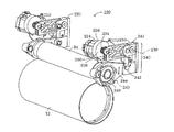
中間作像部材12に対して転写ローラ94を移動させる、従来技術による転写ローラ制御システム120を図2に示す。システム120は、転写ローラ94の一端における転写ローラ制御アセンブリ210と、転写ローラ94の他端における転写ローラ制御アセンブリ220とを備える。転写ローラ制御アセンブリ210および220は本質的に同じなので、以下の説明はローラ制御アセンブリ210についてのみ行なう。アセンブリ210は、その出力シャフト上にプーリ(図示せず)を有するモータ224を備える。エンドレスベルト228は、モータ224の出力シャフト上のプーリ、およびプーリ230の周囲に巻き掛けられている。プーリ230はその中央に、セクタギヤ238の歯に係合するギヤ歯234を有する。セクタギヤ238の外側端部には、保持アーム244に対するリンク240が取り付けられる。保持アーム244内には、転写ローラ94の一端を受容するようにジャーナル軸受248が取り付けられた開口が存する。保持アーム244の近端にはピボットピンがあるので、リンク240の動きにより調整されるように、保持アーム244が軸243を中心として回転することができる。転写ローラ制御アセンブリ220も同様に配設される。
A prior art transfer
制御装置がモータ224を動作させるため信号を発生させると、その出力シャフトが回転することによりエンドレスベルト228がプーリ230を回転させる。プーリ230が回転すると、ギヤ歯234が軸受軸239を中心としてセクタギヤ238を回転させる。セクタギヤ238の外側端部におけるリンク240は、ピボットピン241によりセクタギヤ238に連結され、ピボットピン242により保持アーム244に連結されている。セクタギヤ238の回転によりリンク240が移動し、リンク240により保持アーム244が軸243を中心として回転する。このようにして、軸受248内の転写ローラの端部はモータ224の双方向制御により移動する。アセンブリ210内のモータ224およびアセンブリ220内の対応するモータの動作は制御装置により整合され、転写ローラ94が作像部材12との係合および係合解除状態へ円滑に移動するようになっている。ある実施形態では、これらモータの動作は独立して制御される。アセンブリ210および220は、リンク240に取り付けられたひずみゲージまたはリンク240のたわみを計測するセンサのようなセンサを備えてもよい。これらアセンブリ内のセンサは、転写ローラ94により作像部材12に加えられている圧力の示度を与える。アセンブリ210および220内のモータを制御することにより作像部材12に対する転写ローラ94の力を調整する信号の調整のためのフィードバックとして、圧力信号を制御装置により用いることができる。
When the control device generates a signal to operate the
転写ローラ制御アセンブリの一実施形態を説明してきたが、他の実施形態を用いてもよい。他の実施形態は、転写ローラの各端部ごとにローラ制御アセンブリで構成してもよく、転写ローラの両端部を制御する単一のアセンブリで構成してもよい。様々な転写ローラ制御の実施形態に必要なのは、転写ローラ制御が変位可能なリンク機構として動作し、リンク機構をある移動範囲内で移動させる制御信号に応じて、転写ローラを作像部材との係合状態および係合解除状態へ移動させることである。この移動範囲は一端が作像部材からの係合解除状態として規定され、範囲の他端は、十分な圧力で作像部材に対して押圧され転写ニップを形成している状態として規定される。 While one embodiment of the transfer roller control assembly has been described, other embodiments may be used. Other embodiments may comprise a roller control assembly for each end of the transfer roller or a single assembly that controls both ends of the transfer roller. What is needed for various transfer roller control embodiments is that the transfer roller control operates as a displaceable link mechanism, and the transfer roller is associated with the imaging member in response to a control signal that moves the link mechanism within a range of movement. Moving to the combined state and the disengaged state. One end of the moving range is defined as a state of disengagement from the image forming member, and the other end of the range is defined as a state where the transfer member is pressed against the image forming member with sufficient pressure to form a transfer nip.
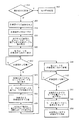
以下でより詳細に説明するシステムおよび方法は、変位可能なリンク機構を動作させ、図3に示すものなど、転写段階の間のある方法を実現するものである。図4は、図3に示すプロセスの間における作像部材12に対する転写ローラ94の物理的関係を示している。プロセス300において、媒体厚さが未知であることを示す事象が発生する(ブロック304)。そうでない場合、プリンタはその印刷動作を続行する(ブロック302)。上記事象は例えば、ある画像に関するバイパストレイからの媒体シートの選択、ある印刷ジョブのためシートが引き出される媒体トレイの開放、または作像部材駆動ベルトに関するすべりの検出であってもよい。印刷プロセスが開始されるとともに、作像部材上に画像が形成される(ブロック308)。作像部材の回転は、印刷サイクルの間に転写ニップが形成されるであろう位置に達する所定距離だけ手前で停止される(ブロック312)。ある実施形態では、作像部材は、転写ニップが代表的に形成される位置のおよそ30mm手前で停止される。図4においては位置1であるこの位置では、媒体シートは、作像部材と接触する位置まで完全に前進してはいない。この位置において、制御装置は、転写ローラの前端を移動させるモータの初期位置と、転写ローラの後端を移動させるモータの初期位置とを読み取る(ブロック316)。制御装置は、転写ローラの端部に連結された各モータに関して転写荷重信号を発生させ、転写ローラを移動させて作像部材と接触させ、転写ニップを形成する(ブロック320)。この位置は図4において位置2として示される。転写ローラは画像間区域において作像部材と接触する。作像部材との接触は、作像部材との転写ローラの接触に応答して信号を発生させる圧力センサにより検出される。発生する信号は、中間作像部材により転写ローラに加えられる圧力に対応している。作像部材の接触を示す所定のしきい値を超えるこの圧力信号を検出すると(ブロック322)、制御装置は、転写ローラの前端および後端を移動させたモータの位置を読み取る(ブロック324)。次に制御装置は転写非荷重信号を発生させ、モータが作動して、図4の位置3で示すように転写ローラを接触位置からその初期位置まで後退させる(ブロック328)。
The systems and methods described in more detail below operate a displaceable link mechanism to implement some method during the transfer phase, such as that shown in FIG. FIG. 4 shows the physical relationship of the
制御装置は、媒体経路内のコンベヤを作動させ、図4の位置4で示すように転写ニップが形成される領域内へ媒体シートを前進させる媒体前進信号を発生させる(ブロック332)。好ましくは、媒体シートの前進中は作像部材は移動せず、次の計測サイクルの間に転写ニップを形成する作像部材の表面積にほとんど、あるいはまったく差異が生じないようになっている。しかしある実施形態では、作像部材に関するおよそ50mmの小さい変位は許容可能と見なされる。再び制御装置は、転写ローラの前端を移動させるモータの初期位置と、転写ローラの後端を移動させるモータの初期位置とを読み取る(ブロック336)。次に制御装置は、転写ローラの端部に連結された各モータに関して別の転写荷重信号を発生させ、転写ローラを作像部材に向けて移動させて、ニップ内の画像基材に対し転写ニップを形成する(ブロック340)。この位置は図4において位置5として示される。ニップ内の画像基材に対する転写ローラの接触は、作像部材の接触を示す所定のしきい値を超える圧力センサ信号により検出される(ブロック342)。制御装置は、転写ローラの前端および後端を移動させたモータの位置を読み取る(ブロック344)。次に制御装置は、以下でより詳細に説明するように、モータ変位の読取り値を用いて媒体シートの厚さを計算する(ブロック348)。計測された媒体が引き出されたトレイの開放など、厚さ計測の精度に悪影響を与えることのある事象が発生するまで、この計測された厚さを用いて印刷パラメータを調整することができる。次に制御装置は、図4の位置6として示される、画像基材に対する画像の転写を完結させる信号を発生させる(ブロック350)。
The controller activates the conveyor in the media path and generates a media advance signal that advances the media sheet into the area where the transfer nip is formed, as indicated by
図5のグラフでは、媒体厚さを計測するプロセスを説明するため2本の線が表示されている。上側の線504は、作像部材により転写ローラに加えられる力のグラフである。転写ローラが作像部材から後退すると、上記の力は0ニュートンになる。転写ローラが作像部材に対し完全に荷重されると、上記の力はおよそ5100ニュートンとなる(グラフの線504に関する力の単位は100ニュートンである)。このプリンタに関し、作像部材との接触を検出するための所定のしきい値は150ニュートンである。下側の線510は、転写サイクルの間のモータ変位のグラフである。ある実施形態では、使用されるモータは、所定数のステップがモータの1回転と等しいのでステッパモータと呼ばれる。例えば、ある実施形態は、200モータステップで1回転するステッパモータを用いる。図5に示すモータ変位の単位はステップである。位置514はモータの初期位置に対応しており、位置518は、作像部材に対する転写ローラの接触が検出される際のモータ変位に対応している。同様に、画像基材が転写ニップ内に位置する次の転写サイクルには、初期モータ位置および転写ニップ内における転写ローラの媒体接触が検出される際のモータ位置にそれぞれ対応する位置520および位置524が含まれる。位置518および514におけるステップ数の間の差異により、ニップ内に媒体シートが存しない転写サイクルの間のモータ変位の計測値が得られ、位置524および520におけるステップ数の間の差異により、ニップ内に媒体シートが位置する転写サイクルの間のモータ変位の計測値が得られる。2つの差異の差により、媒体厚さの計測値が同定される。
In the graph of FIG. 5, two lines are displayed to explain the process of measuring the media thickness. The upper line 504 is a graph of the force applied to the transfer roller by the imaging member. When the transfer roller is retracted from the image forming member, the above force becomes 0 Newton. When the transfer roller is fully loaded against the imaging member, the force is approximately 5100 Newtons (the unit of force for graph line 504 is 100 Newtons). For this printer, the predetermined threshold for detecting contact with the imaging member is 150 Newtons. The
第1の転写サイクルを図6において、より詳細に示す。位置604において、制御装置は、モータの初期位置を読み取り、転写ローラに加わっている力をモニタし始める。転写力が所定のしきい値である150ニュートンを超えると、モータ位置(位置608)が再びサンプリングされる。ある実施形態では、転写ローラの前端に関するモータおよび転写ローラの後端に関するモータ双方の変位が計測される。前方および後方のモータの相対的変位に基づく計測演算を記述する等式は次のように表わすことができる。
The first transfer cycle is shown in more detail in FIG. At
t=[(D2F−S2F−D1F+S1F)+(D2R−S2R−D1R+S1R)]/2/SF t = [(D2F-S2F-D1F + S1F) + (D2R-S2R-D1R + S1R)] / 2 / SF
式中、tは媒体厚さ、S1FおよびS1Rは第1の転写サイクルに関する前方および後方のモータそれぞれの開始位置、S2FおよびS2Rは第2の転写サイクルに関する前方および後方のモータそれぞれの開始位置、D1FおよびD1Rは第1の転写サイクルに関する前方および後方のモータそれぞれの接触位置、D2FおよびD2Rは第2の転写サイクルに関する前方および後方のモータそれぞれの接触位置、SFはモータステップを線形の計測単位に変換するための換算係数である。ある実施形態では、換算係数は170.4549ステップ/mmである。2で除算することにより、2つのモータ変位の平均が得られる。読者は、前方側モータの機械的開始位置S1FおよびS2Fおよび後方側モータの機械的開始位置S1RおよびS2Rは定数であることに留意すべきである。変位を計測するための基準系が不変の場合、相対的開始位置の値は等しく、絶対的モータ位置のみを用いて厚さを計算することができる。上記の等式は以下のように縮小可能である。 Where t is the media thickness, S1F and S1R are the start positions of the front and rear motors for the first transfer cycle, S2F and S2R are the start positions of the front and rear motors for the second transfer cycle, D1F And D1R are the front and rear motor contact positions for the first transfer cycle, D2F and D2R are the front and rear motor contact positions for the second transfer cycle, and SF is the motor step converted into a linear unit of measure. It is a conversion factor for In one embodiment, the conversion factor is 170.4549 steps / mm. Dividing by 2 gives the average of the two motor displacements. The reader should note that the mechanical start positions S1F and S2F of the front motor and the mechanical start positions S1R and S2R of the rear motor are constants. If the reference system for measuring displacement is unchanged, the relative start position values are equal and the thickness can be calculated using only the absolute motor position. The above equation can be reduced as follows.
S1F=S2F かつ S1R=S2Rなのでt=[(D2F−D1F)+(D2R−D1R)]/2/SF Since S1F = S2F and S1R = S2R, t = [(D2F−D1F) + (D2R−D1R)] / 2 / SF
厚さ計算の一例を、以下の表に示す。 An example of thickness calculation is shown in the table below.

本例における実際の媒体厚さは0.21mmであった。結果として、計算された媒体厚さの誤差は−5%であった。 The actual medium thickness in this example was 0.21 mm. As a result, the calculated media thickness error was -5%.
経験的方法を用い、計測精度改善のためのより最適な値を決定するため、転写ローラ速度、転写ローラ接触力しきい値、力のサンプリング速度など、計測プロセスを制御する様々なパラメータを試験した。オフセットの包含および最終の等式における利得をもたらす線形回帰技法を用いることにより、さらなる改善を行なった。相対的変位に基づいて変更された等式は、次のとおりである。 Empirical methods were used to test various parameters that control the measurement process, such as transfer roller speed, transfer roller contact force threshold, and force sampling rate, to determine more optimal values for improved measurement accuracy. . Further improvements were made by using linear regression techniques that yielded offset inclusion and gain in the final equation. The equation modified based on the relative displacement is:
t={[[(D2F−S2F−D1F+S1F)+(D2R−S2R−D1R+S1R)]/2/SF]−オフセット}/利得 t = {[[(D2F-S2F-D1F + S1F) + (D2R-S2R-D1R + S1R)] / 2 / SF] -offset} / gain
または、絶対的変位に基づいた場合、次のように表すことができる。 Or, based on absolute displacement, it can be expressed as:
t={[[(D2F−D1F)+(D2R−D1R)]/2/SF]−オフセット}/利得 t = {[[((D2F-D1F) + (D2R-D1R)] / 2 / SF] -offset} / gain
経験的に導出したパラメータは、最小サンプリング速度が1.5kHz、最大転写ローラ速度が10mm/秒、作像部材接触しきい値が450ニュートン、換算係数が170.4549ステップ/mm、オフセットが−0.016390mm、利得が1.028331となるように決定した。これらの変化は、媒体厚さ計測値の精度をおよそ5.4%以内に改善するものと予測され、およそ6.5ミクロンの分解能を実現する。この精度の変化は上記5%の誤差を実現する例に対する改善ではないが、一群のプリンタに経験的に導出したパラメータを適用することにより、そのようなパラメータを用いないプリンタで得られる計測値に対し、精度が統計上有意に改善される。 The empirically derived parameters are as follows: the minimum sampling speed is 1.5 kHz, the maximum transfer roller speed is 10 mm / second, the imaging member contact threshold is 450 Newton, the conversion factor is 170.4549 steps / mm, and the offset is −0. 016390 mm, and gain was determined to be 1.028331. These changes are expected to improve the accuracy of the media thickness measurement to within approximately 5.4% and achieve a resolution of approximately 6.5 microns. This change in accuracy is not an improvement over the above example of achieving an error of 5%, but by applying empirically derived parameters to a group of printers, the measured values obtained with a printer that does not use such parameters can be obtained. On the other hand, the accuracy is statistically significantly improved.
動作中、制御装置は、プログラム命令により上記プロセスを実行するように構成される。ある印刷サイクルの間、制御装置は、画像基材の計測を必要とする事象を検出し、2つの転写サイクルを通じて転写ローラを動作させる信号を発生させる。一方のサイクルでは、モータ変位は媒体が転写ニップ内に存していない状態で計測され、他方のサイクルでは、モータ変位は媒体が転写ニップ内にある状態で計測される。制御装置は適切なパラメータとともに厚さの等式を用いて媒体の厚さを計算し、その後、厚さを用いて印刷プロセスパラメータを調整する。 During operation, the controller is configured to execute the above process according to program instructions. During a printing cycle, the controller detects an event that requires measurement of the image substrate and generates a signal to operate the transfer roller through two transfer cycles. In one cycle, the motor displacement is measured with the medium not in the transfer nip, and in the other cycle, the motor displacement is measured with the medium in the transfer nip. The controller uses the thickness equation along with the appropriate parameters to calculate the media thickness, and then uses the thickness to adjust the printing process parameters.
10 高速相変化インク画像作成機またはプリンタ、11 フレーム、12 中間作像部材、14 作像面、16 方向、20 相変化インク給配サブシステム、22、24、26、28 供給源30 印刷ヘッドシステム、 32、34、36、38 印刷ヘッドアセンブリ、40 基材供給取扱いシステム、42、44、46、48 基材供給源、52 基材予熱器、54 基材・画像ヒータ、60 定着装置、70 オリジナル文書フィーダ、72 文書保持トレイ、74 文書シート給送回収装置、76 文書露光走査システム、80 制御装置または電子サブシステム(ESS)、82 中央処理装置(CPU)、84 電子記憶装置、86 表示装置またはユーザインタフェース(UI)、88 センサ入力・制御手段、89 画素配置・制御手段、90 オンライン接続またはワークステーション接続、92 転写ニップ、94 転写ローラ、120 転写ローラ制御システム、210、220 転写ローラ制御アセンブリ、224 モータ、228 エンドレスベルト、230 プーリ、234 ギヤ歯、238 セクタギヤ、239 軸受軸、 240 リンク、241、242 ピボットピン、243 軸、244 保持アーム、248 ジャーナル軸受。
10 High Speed Phase Change Ink Image Creator or Printer, 11 Frame, 12 Intermediate Imaging Member, 14 Imaging Surface, 16 Direction, 20 Phase Change Ink Distribution Subsystem, 22, 24, 26, 28
Claims (8)
中間作像部材に隣接して配置される転写ローラと、
転写ローラを前記中間作像部材から離れた第1の位置から、転写ローラが中間作像部材に対して転写ニップを形成する位置まで移動させ、また転写ローラを前記第1の位置まで戻すように転写ローラに連結された変位可能なリンク機構と、
変位可能なリンク機構に連結された制御装置であって、第1の位置から転写ニップが形成される位置までの転写ローラの移動を計測し、第1の位置から、画像基材が転写ニップ内にない状態で中間作像部材に対し転写ニップが形成される位置までの転写ローラの計測された移動と、第1の位置から、画像基材が転写ローラと中間作像部材との間の転写ニップ内にある状態で転写ニップが形成される位置までの転写ローラの計測された移動とから媒体厚さを計算するように構成されている制御装置と、を備えるプリンタ。 An intermediate imaging member;
A transfer roller disposed adjacent to the intermediate imaging member;
The transfer roller is moved from a first position away from the intermediate image forming member to a position where the transfer roller forms a transfer nip with respect to the intermediate image forming member, and the transfer roller is returned to the first position. A displaceable link mechanism connected to the transfer roller;
A control device connected to a displaceable link mechanism that measures the movement of a transfer roller from a first position to a position where a transfer nip is formed, and from the first position, the image base material moves into the transfer nip. The measured movement of the transfer roller to a position where a transfer nip is formed with respect to the intermediate image forming member in a state where the image base is not located, and the transfer of the image substrate between the transfer roller and the intermediate image forming member from the first position And a controller configured to calculate the media thickness from the measured movement of the transfer roller to a position where the transfer nip is formed while in the nip.
前記転写ローラが中間作像部材から離れた第1の位置から、画像基材がない状態で中間作像部材に接触して転写ニップを形成する位置までの第1の移動を計測し、
前記転写ローラが前記第1の位置から前記転写ニップにある画像基材に接触する位置までの第2の移動を計測し、
前記計測された第1の移動および前記計測された第2の移動から前記画像基材の厚さを計算する、方法。 A method of moving a transfer roller during a printing cycle,
Measuring the first movement from the first position where the transfer roller is away from the intermediate image forming member to the position where the transfer roller is in contact with the intermediate image forming member in the absence of the image base material to form the transfer nip;
Measuring a second movement of the transfer roller from the first position to a position contacting the image substrate in the transfer nip;
Calculating the thickness of the imaging substrate from the measured first movement and the measured second movement.
The measurement of the first movement and the measurement of the second movement are performed when a force acting on the transfer roller from the intermediate image forming member exceeds a predetermined threshold value. Method 7.
Applications Claiming Priority (2)
| Application Number | Priority Date | Filing Date | Title |
|---|---|---|---|
| US12/212,218 | 2008-09-17 | ||
| US12/212,218 US8126362B2 (en) | 2008-09-17 | 2008-09-17 | System and method for measuring media thickness with a transfer subsystem in a printer |
Publications (3)
| Publication Number | Publication Date |
|---|---|
| JP2010069877A JP2010069877A (en) | 2010-04-02 |
| JP2010069877A5 JP2010069877A5 (en) | 2012-10-25 |
| JP5243377B2 true JP5243377B2 (en) | 2013-07-24 |
Family
ID=42007347
Family Applications (1)
| Application Number | Title | Priority Date | Filing Date |
|---|---|---|---|
| JP2009211698A Expired - Fee Related JP5243377B2 (en) | 2008-09-17 | 2009-09-14 | System and method for measuring media thickness with a transfer subsystem in a printer |
Country Status (4)
| Country | Link |
|---|---|
| US (1) | US8126362B2 (en) |
| JP (1) | JP5243377B2 (en) |
| KR (1) | KR101225469B1 (en) |
| CN (1) | CN101676117B (en) |
Families Citing this family (6)
| Publication number | Priority date | Publication date | Assignee | Title |
|---|---|---|---|---|
| US8376501B2 (en) * | 2010-09-14 | 2013-02-19 | Xerox Corporation | Reflex printing |
| US8854634B2 (en) * | 2012-06-14 | 2014-10-07 | Xerox Corporation | Transfix roller with adjustable crown for use in an indirect printer |
| US9688027B2 (en) * | 2014-04-01 | 2017-06-27 | Stratasys, Inc. | Electrophotography-based additive manufacturing with overlay control |
| CN109844446B (en) * | 2017-01-19 | 2022-09-30 | 惠普发展公司,有限责任合伙企业 | Printer system and method for measuring thickness of printing medium |
| CN111417524B (en) * | 2017-11-13 | 2022-03-29 | 惠普发展公司,有限责任合伙企业 | Method of determining change of printing medium, storage medium, and system for printing |
| CN111660678B (en) * | 2020-06-30 | 2023-11-21 | 厦门汉印电子技术有限公司 | Device and method for detecting rotation amount of printing roller and printer |
Family Cites Families (22)
| Publication number | Priority date | Publication date | Assignee | Title |
|---|---|---|---|---|
| KR100230318B1 (en) * | 1997-07-30 | 1999-11-15 | 윤종용 | Pressure controlling apparatus for laser printer |
| JP2000272792A (en) * | 1999-03-26 | 2000-10-03 | Seiko Epson Corp | Feeder for printer |
| JP2000296946A (en) | 1999-04-08 | 2000-10-24 | Seiko Epson Corp | Paper thickness measuring method for printer |
| JP2000313545A (en) | 1999-04-28 | 2000-11-14 | Canon Inc | Image forming device and controlling method therefor |
| KR100350986B1 (en) * | 2000-02-21 | 2002-08-28 | 삼성전자 주식회사 | Printer and method of controlling the gap of fusing roller |
| JP2001282013A (en) * | 2000-03-31 | 2001-10-12 | Murata Mach Ltd | Image forming device |
| JP2002116679A (en) * | 2000-07-31 | 2002-04-19 | Ricoh Co Ltd | Image forming apparatus and image forming method |
| US6389242B1 (en) * | 2000-09-15 | 2002-05-14 | Toshiba Tec Kabushiki Kaisha | Image forming apparatus and image forming method |
| US7136600B2 (en) * | 2002-02-28 | 2006-11-14 | Ricoh Company, Ltd. | Image forming apparatus including controller driving image carriers |
| JP2003269904A (en) * | 2002-03-19 | 2003-09-25 | Canon Inc | Instrument for measuring thickness of paper sheet |
| US6698877B2 (en) * | 2002-06-28 | 2004-03-02 | Kimberly-Clark Worldwide, Inc. | Offset printing apparatus for applying a substance |
| US6585368B1 (en) * | 2002-08-01 | 2003-07-01 | Xerox Corporation | Gear clutch assembly and method for operating a transfix roller and a drum maintenance system |
| US6839242B2 (en) * | 2003-02-13 | 2005-01-04 | Rincon Research Corporation | Reconfigurable circuit modules |
| US6731891B1 (en) * | 2003-06-13 | 2004-05-04 | Xerox Corproation | Transfer roll engagement method for minimizing motion quality disturbances |
| US7325917B2 (en) * | 2005-04-25 | 2008-02-05 | Xerox Corporation | Phase change ink transfix pressure component with three-layer configuration |
| US7817957B2 (en) * | 2005-07-08 | 2010-10-19 | Ricoh Company, Ltd. | Double feed sensing device, double feed determining method and image forming apparatus |
| US7396107B2 (en) * | 2005-08-02 | 2008-07-08 | Xerox Corporation | Ink jet printing with low coverage second pass |
| US7798633B2 (en) * | 2005-11-14 | 2010-09-21 | Xerox Corporation | Ink printer using forward direction printing process |
| US7458671B2 (en) * | 2005-12-21 | 2008-12-02 | Xerox Corporation | Ink printer having improved release agent application control |
| JP2008126618A (en) * | 2006-11-24 | 2008-06-05 | Canon Inc | Recording device, conveying device, and conveying method |
| JP4931664B2 (en) * | 2007-03-27 | 2012-05-16 | 株式会社沖データ | Image forming apparatus |
| US7860417B2 (en) * | 2008-09-12 | 2010-12-28 | Xerox Corporation | System and method for varying transfer pressure applied by a transfer roller in a printer |
-
2008
- 2008-09-17 US US12/212,218 patent/US8126362B2/en not_active Expired - Fee Related
-
2009
- 2009-09-14 JP JP2009211698A patent/JP5243377B2/en not_active Expired - Fee Related
- 2009-09-16 CN CN2009101734355A patent/CN101676117B/en not_active Expired - Fee Related
- 2009-09-16 KR KR1020090087316A patent/KR101225469B1/en not_active IP Right Cessation
Also Published As
| Publication number | Publication date |
|---|---|
| US8126362B2 (en) | 2012-02-28 |
| JP2010069877A (en) | 2010-04-02 |
| US20100067948A1 (en) | 2010-03-18 |
| CN101676117A (en) | 2010-03-24 |
| CN101676117B (en) | 2013-10-16 |
| KR101225469B1 (en) | 2013-01-24 |
| KR20100032332A (en) | 2010-03-25 |
Similar Documents
| Publication | Publication Date | Title |
|---|---|---|
| JP5243377B2 (en) | System and method for measuring media thickness with a transfer subsystem in a printer | |
| US9724933B2 (en) | Thermal transfer printer | |
| JP4861545B2 (en) | Ink adjustment method for printing on a printing press | |
| EP3354609B1 (en) | Transport device and printing apparatus | |
| US7942517B2 (en) | Method for lubricating a transfer roller with an image member | |
| US8358438B2 (en) | Apparatuses and methods for automatic printing press optimization | |
| US8814313B2 (en) | System and method for adjusting the tension of a continuous web of recording media in a printer | |
| JP5279668B2 (en) | Printer and method for changing transfer pressure applied by transfer roller in printer | |
| US11142418B2 (en) | Image forming device, paper feeding mechanism deterioration determining method and non-transitory recording medium | |
| US8827410B2 (en) | Method and apparatus for cleaning a heated drum within a continuous web printer | |
| US6929342B2 (en) | Media-position sensor system | |
| JP5928098B2 (en) | Electrical device and setting method | |
| JP2016098082A (en) | Liquid discharge device and conveyance method for sheet in the same | |
| US11518181B2 (en) | Printing apparatus | |
| JP5838597B2 (en) | Web mark detection method and image forming apparatus | |
| JPH08211780A (en) | Image forming device | |
| JP2005205737A (en) | Liquid ejection device |
Legal Events
| Date | Code | Title | Description |
|---|---|---|---|
| A521 | Written amendment |
Free format text: JAPANESE INTERMEDIATE CODE: A523 Effective date: 20120910 |
|
| A621 | Written request for application examination |
Free format text: JAPANESE INTERMEDIATE CODE: A621 Effective date: 20120910 |
|
| A871 | Explanation of circumstances concerning accelerated examination |
Free format text: JAPANESE INTERMEDIATE CODE: A871 Effective date: 20120910 |
|
| A975 | Report on accelerated examination |
Free format text: JAPANESE INTERMEDIATE CODE: A971005 Effective date: 20121001 |
|
| A131 | Notification of reasons for refusal |
Free format text: JAPANESE INTERMEDIATE CODE: A131 Effective date: 20121113 |
|
| A521 | Written amendment |
Free format text: JAPANESE INTERMEDIATE CODE: A523 Effective date: 20130107 |
|
| TRDD | Decision of grant or rejection written | ||
| A01 | Written decision to grant a patent or to grant a registration (utility model) |
Free format text: JAPANESE INTERMEDIATE CODE: A01 Effective date: 20130319 |
|
| A61 | First payment of annual fees (during grant procedure) |
Free format text: JAPANESE INTERMEDIATE CODE: A61 Effective date: 20130404 |
|
| FPAY | Renewal fee payment (event date is renewal date of database) |
Free format text: PAYMENT UNTIL: 20160412 Year of fee payment: 3 |
|
| R150 | Certificate of patent or registration of utility model |
Free format text: JAPANESE INTERMEDIATE CODE: R150 Ref document number: 5243377 Country of ref document: JP Free format text: JAPANESE INTERMEDIATE CODE: R150 |
|
| R250 | Receipt of annual fees |
Free format text: JAPANESE INTERMEDIATE CODE: R250 |
|
| R250 | Receipt of annual fees |
Free format text: JAPANESE INTERMEDIATE CODE: R250 |
|
| R250 | Receipt of annual fees |
Free format text: JAPANESE INTERMEDIATE CODE: R250 |
|
| LAPS | Cancellation because of no payment of annual fees |