JP5242700B2 - Beamforming in MIMO systems - Google Patents
Beamforming in MIMO systems Download PDFInfo
- Publication number
- JP5242700B2 JP5242700B2 JP2010539723A JP2010539723A JP5242700B2 JP 5242700 B2 JP5242700 B2 JP 5242700B2 JP 2010539723 A JP2010539723 A JP 2010539723A JP 2010539723 A JP2010539723 A JP 2010539723A JP 5242700 B2 JP5242700 B2 JP 5242700B2
- Authority
- JP
- Japan
- Prior art keywords
- beamforming
- transceiver
- vector
- codebook
- transmitting
- Prior art date
- Legal status (The legal status is an assumption and is not a legal conclusion. Google has not performed a legal analysis and makes no representation as to the accuracy of the status listed.)
- Active
Links
- 239000013598 vector Substances 0.000 claims description 195
- 238000000034 method Methods 0.000 claims description 90
- 238000012549 training Methods 0.000 claims description 50
- 230000005540 biological transmission Effects 0.000 claims description 48
- 230000000295 complement effect Effects 0.000 claims description 22
- 230000011664 signaling Effects 0.000 claims description 10
- 230000010287 polarization Effects 0.000 claims description 4
- 239000011159 matrix material Substances 0.000 description 51
- 230000006870 function Effects 0.000 description 14
- 238000004891 communication Methods 0.000 description 12
- 230000008878 coupling Effects 0.000 description 10
- 238000010168 coupling process Methods 0.000 description 10
- 238000005859 coupling reaction Methods 0.000 description 10
- 238000003491 array Methods 0.000 description 8
- 238000012545 processing Methods 0.000 description 8
- 230000008901 benefit Effects 0.000 description 7
- 238000010586 diagram Methods 0.000 description 6
- 238000004364 calculation method Methods 0.000 description 4
- 229920008347 Cellulose acetate propionate Polymers 0.000 description 3
- 238000009470 controlled atmosphere packaging Methods 0.000 description 3
- 125000004122 cyclic group Chemical group 0.000 description 3
- 238000013507 mapping Methods 0.000 description 3
- 238000012986 modification Methods 0.000 description 3
- 230000004048 modification Effects 0.000 description 3
- 230000000737 periodic effect Effects 0.000 description 3
- 230000008569 process Effects 0.000 description 3
- OFMQLVRLOGHAJI-FGHAYEPSSA-N (4r,7s,10s,13r,16s,19r)-n-[(2s,3r)-1-amino-3-hydroxy-1-oxobutan-2-yl]-19-[[(2r)-2-amino-3-phenylpropanoyl]amino]-10-[3-(diaminomethylideneamino)propyl]-7-[(1r)-1-hydroxyethyl]-16-[(4-hydroxyphenyl)methyl]-13-(1h-indol-3-ylmethyl)-3,3-dimethyl-6,9,12,15,18 Chemical compound C([C@H]1C(=O)N[C@H](CC=2C3=CC=CC=C3NC=2)C(=O)N[C@@H](CCCNC(N)=N)C(=O)N[C@H](C(=O)N[C@@H](C(SSC[C@@H](C(=O)N1)NC(=O)[C@H](N)CC=1C=CC=CC=1)(C)C)C(=O)N[C@@H]([C@H](O)C)C(N)=O)[C@@H](C)O)C1=CC=C(O)C=C1 OFMQLVRLOGHAJI-FGHAYEPSSA-N 0.000 description 2
- 239000000654 additive Substances 0.000 description 2
- 230000000996 additive effect Effects 0.000 description 2
- 238000013139 quantization Methods 0.000 description 2
- 241000282376 Panthera tigris Species 0.000 description 1
- 230000003044 adaptive effect Effects 0.000 description 1
- 230000002457 bidirectional effect Effects 0.000 description 1
- 238000012937 correction Methods 0.000 description 1
- 230000007547 defect Effects 0.000 description 1
- 238000001514 detection method Methods 0.000 description 1
- 235000019800 disodium phosphate Nutrition 0.000 description 1
- 230000009977 dual effect Effects 0.000 description 1
- 238000005516 engineering process Methods 0.000 description 1
- 238000001914 filtration Methods 0.000 description 1
- 230000003993 interaction Effects 0.000 description 1
- 230000004044 response Effects 0.000 description 1
- 238000005070 sampling Methods 0.000 description 1
- 238000004088 simulation Methods 0.000 description 1
- 238000006467 substitution reaction Methods 0.000 description 1
Images


Classifications
-
- H—ELECTRICITY
- H04—ELECTRIC COMMUNICATION TECHNIQUE
- H04B—TRANSMISSION
- H04B7/00—Radio transmission systems, i.e. using radiation field
- H04B7/02—Diversity systems; Multi-antenna system, i.e. transmission or reception using multiple antennas
- H04B7/04—Diversity systems; Multi-antenna system, i.e. transmission or reception using multiple antennas using two or more spaced independent antennas
- H04B7/06—Diversity systems; Multi-antenna system, i.e. transmission or reception using multiple antennas using two or more spaced independent antennas at the transmitting station
- H04B7/0613—Diversity systems; Multi-antenna system, i.e. transmission or reception using multiple antennas using two or more spaced independent antennas at the transmitting station using simultaneous transmission
- H04B7/0615—Diversity systems; Multi-antenna system, i.e. transmission or reception using multiple antennas using two or more spaced independent antennas at the transmitting station using simultaneous transmission of weighted versions of same signal
- H04B7/0617—Diversity systems; Multi-antenna system, i.e. transmission or reception using multiple antennas using two or more spaced independent antennas at the transmitting station using simultaneous transmission of weighted versions of same signal for beam forming
-
- H—ELECTRICITY
- H04—ELECTRIC COMMUNICATION TECHNIQUE
- H04B—TRANSMISSION
- H04B7/00—Radio transmission systems, i.e. using radiation field
- H04B7/02—Diversity systems; Multi-antenna system, i.e. transmission or reception using multiple antennas
- H04B7/04—Diversity systems; Multi-antenna system, i.e. transmission or reception using multiple antennas using two or more spaced independent antennas
- H04B7/0413—MIMO systems
- H04B7/0417—Feedback systems
-
- H—ELECTRICITY
- H04—ELECTRIC COMMUNICATION TECHNIQUE
- H04B—TRANSMISSION
- H04B1/00—Details of transmission systems, not covered by a single one of groups H04B3/00 - H04B13/00; Details of transmission systems not characterised by the medium used for transmission
- H04B1/69—Spread spectrum techniques
- H04B1/7163—Spread spectrum techniques using impulse radio
-
- H—ELECTRICITY
- H04—ELECTRIC COMMUNICATION TECHNIQUE
- H04B—TRANSMISSION
- H04B7/00—Radio transmission systems, i.e. using radiation field
- H04B7/02—Diversity systems; Multi-antenna system, i.e. transmission or reception using multiple antennas
- H04B7/04—Diversity systems; Multi-antenna system, i.e. transmission or reception using multiple antennas using two or more spaced independent antennas
- H04B7/06—Diversity systems; Multi-antenna system, i.e. transmission or reception using multiple antennas using two or more spaced independent antennas at the transmitting station
- H04B7/0613—Diversity systems; Multi-antenna system, i.e. transmission or reception using multiple antennas using two or more spaced independent antennas at the transmitting station using simultaneous transmission
- H04B7/0615—Diversity systems; Multi-antenna system, i.e. transmission or reception using multiple antennas using two or more spaced independent antennas at the transmitting station using simultaneous transmission of weighted versions of same signal
- H04B7/0619—Diversity systems; Multi-antenna system, i.e. transmission or reception using multiple antennas using two or more spaced independent antennas at the transmitting station using simultaneous transmission of weighted versions of same signal using feedback from receiving side
- H04B7/0621—Feedback content
- H04B7/0626—Channel coefficients, e.g. channel state information [CSI]
-
- H—ELECTRICITY
- H04—ELECTRIC COMMUNICATION TECHNIQUE
- H04B—TRANSMISSION
- H04B7/00—Radio transmission systems, i.e. using radiation field
- H04B7/02—Diversity systems; Multi-antenna system, i.e. transmission or reception using multiple antennas
- H04B7/04—Diversity systems; Multi-antenna system, i.e. transmission or reception using multiple antennas using two or more spaced independent antennas
- H04B7/06—Diversity systems; Multi-antenna system, i.e. transmission or reception using multiple antennas using two or more spaced independent antennas at the transmitting station
- H04B7/0613—Diversity systems; Multi-antenna system, i.e. transmission or reception using multiple antennas using two or more spaced independent antennas at the transmitting station using simultaneous transmission
- H04B7/0615—Diversity systems; Multi-antenna system, i.e. transmission or reception using multiple antennas using two or more spaced independent antennas at the transmitting station using simultaneous transmission of weighted versions of same signal
- H04B7/0619—Diversity systems; Multi-antenna system, i.e. transmission or reception using multiple antennas using two or more spaced independent antennas at the transmitting station using simultaneous transmission of weighted versions of same signal using feedback from receiving side
- H04B7/0621—Feedback content
- H04B7/0634—Antenna weights or vector/matrix coefficients
-
- H—ELECTRICITY
- H04—ELECTRIC COMMUNICATION TECHNIQUE
- H04B—TRANSMISSION
- H04B7/00—Radio transmission systems, i.e. using radiation field
- H04B7/02—Diversity systems; Multi-antenna system, i.e. transmission or reception using multiple antennas
- H04B7/04—Diversity systems; Multi-antenna system, i.e. transmission or reception using multiple antennas using two or more spaced independent antennas
- H04B7/06—Diversity systems; Multi-antenna system, i.e. transmission or reception using multiple antennas using two or more spaced independent antennas at the transmitting station
- H04B7/0613—Diversity systems; Multi-antenna system, i.e. transmission or reception using multiple antennas using two or more spaced independent antennas at the transmitting station using simultaneous transmission
- H04B7/0684—Diversity systems; Multi-antenna system, i.e. transmission or reception using multiple antennas using two or more spaced independent antennas at the transmitting station using simultaneous transmission using different training sequences per antenna
-
- H—ELECTRICITY
- H04—ELECTRIC COMMUNICATION TECHNIQUE
- H04L—TRANSMISSION OF DIGITAL INFORMATION, e.g. TELEGRAPHIC COMMUNICATION
- H04L25/00—Baseband systems
- H04L25/02—Details ; arrangements for supplying electrical power along data transmission lines
- H04L25/0202—Channel estimation
- H04L25/0204—Channel estimation of multiple channels
-
- H—ELECTRICITY
- H04—ELECTRIC COMMUNICATION TECHNIQUE
- H04B—TRANSMISSION
- H04B7/00—Radio transmission systems, i.e. using radiation field
- H04B7/02—Diversity systems; Multi-antenna system, i.e. transmission or reception using multiple antennas
- H04B7/04—Diversity systems; Multi-antenna system, i.e. transmission or reception using multiple antennas using two or more spaced independent antennas
- H04B7/06—Diversity systems; Multi-antenna system, i.e. transmission or reception using multiple antennas using two or more spaced independent antennas at the transmitting station
- H04B7/0686—Hybrid systems, i.e. switching and simultaneous transmission
- H04B7/0695—Hybrid systems, i.e. switching and simultaneous transmission using beam selection
Landscapes
- Engineering & Computer Science (AREA)
- Computer Networks & Wireless Communication (AREA)
- Signal Processing (AREA)
- Physics & Mathematics (AREA)
- Mathematical Physics (AREA)
- Power Engineering (AREA)
- Radio Transmission System (AREA)
- Mobile Radio Communication Systems (AREA)
Description
本発明は、一般にワイヤレス通信システムに関し、より詳細には、ミリメートル波ワイヤレス通信システムにおけるビームフォーミングに関する。 The present invention relates generally to wireless communication systems, and more particularly to beamforming in millimeter wave wireless communication systems.
関連技術の一態様では、シングルキャリアおよびOFDM変調をサポートするデュアルモード超広帯域(UWB)物理層はコモンモードを使用する。UWB物理層はミリメートル波(たとえば、60GHz)通信に使用できる。コモンモードは、ビーコニング(beaconing)、ネットワーク制御シグナリング、およびベースレートデータ通信のために、シングルキャリアデバイスとOFDMデバイスの両方によって使用されるシングルキャリアモードである。コモンモードは、一般に、異なるデバイスと異なるネットワークとの間のインターオペラビリティ(interoperability)のために必要である。 In one aspect of the related art, a dual mode ultra-wideband (UWB) physical layer that supports single carrier and OFDM modulation uses common mode. The UWB physical layer can be used for millimeter wave (eg, 60 GHz) communications. Common mode is a single carrier mode used by both single carrier devices and OFDM devices for beaconing, network control signaling, and base rate data communications. Common mode is generally necessary for interoperability between different devices and different networks.
ミリメートル波通信はまた、空間ダイバーシチ(spatial diversity)とアレイ利得の両方を与えるためにMIMO(多入力多出力)ビームフォーミングを使用することができる。固有ビームフォーミングなどの従来のビームフォーミング(beamforming)では、チャネル状態情報行列またはビームフォーミング行列を送信アレイに戻す必要がある。IEEE802.11n MAC/PHY仕様D0.04、2006年3月は、フィードバック行列の行および列のサイズと、サブキャリアグルーピングサイズ(またはクラスタサイズ)と、量子化ビットサイズと、最低サブキャリアインデックスから最高サブキャリアインデックスへの順序で開始する実際の量子化されたデータ要素のアレイとを含むフィードバック情報を指定している。プリコーディング行列(precoding matrices)を使用するビームフォーミングでは、IEEE802.16e MAC/PHY仕様D12、2005年、ならびにD. J. Love、R. W. Heath Jr、およびT. Strohmer、「Grassmannian Beamforming for Multiple-Input Multiple-Output Wireless Systems」(IEEE Trans. Information Theory、Vol. 49、No. 10、2003年10月、2735〜2747ページ)に記載されているように、ビームフォーミング行列成分の代わりにプリコーディング行列コードブックのインデックスを使用して、フィードバック情報を低減することができる。 Millimeter wave communication can also use MIMO (multiple input multiple output) beamforming to provide both spatial diversity and array gain. Conventional beamforming, such as eigenbeamforming, requires a channel state information matrix or beamforming matrix to be returned to the transmit array. IEEE802.11n MAC / PHY specification D0.04, March 2006 is the highest from feedback matrix row and column size, subcarrier grouping size (or cluster size), quantization bit size, and lowest subcarrier index. Feedback information is specified, including the actual quantized data element array starting in order to the subcarrier index. For beamforming using precoding matrices, IEEE 802.16e MAC / PHY specification D12, 2005, and DJ Love, RW Heath Jr, and T. Strohmer, “Grassmannian Beamforming for Multiple-Input Multiple-Output Wireless. Systems "(IEEE Trans. Information Theory, Vol. 49, No. 10, October 2003, pages 2735-2747), the index of the precoding matrix codebook is used instead of the beamforming matrix component. It can be used to reduce feedback information.
本明細書で開示する実施形態は、UWB信号を使用するシステムに有利である。ただし、他のワイヤレスシステムが同様の利点から利益を得ることができるので、本発明はそのようなシステムに限定されるものではない。 The embodiments disclosed herein are advantageous for systems that use UWB signals. However, the invention is not limited to such systems, as other wireless systems can benefit from similar advantages.
本発明の一実施形態では、ピコネット(piconet)コントローラは、1つまたは複数のワイヤレス加入者デバイスにシグナリングするためにフレームフォーマットを使用する。ピコネットコントローラおよび1つまたは複数の加入者デバイスの各々はアンテナアレイを使用する。ピコネットコントローラは、複数の送信セグメントを備えるフレームフォーマットをもつ信号を送信し、複数の送信セグメントの各々は、所定のビームフォーミングコードブックからの異なるビームパターンを用いて送信される。 In one embodiment of the present invention, the piconet controller uses a frame format to signal to one or more wireless subscriber devices. Each piconet controller and one or more subscriber devices use an antenna array. The piconet controller transmits a signal having a frame format comprising a plurality of transmission segments, each of the plurality of transmission segments being transmitted using a different beam pattern from a predetermined beamforming codebook.
フレームフォーマットはまた、ピコネットコントローラが1つまたは複数の加入者デバイスからのフィードバック(たとえば、確認応答)をリッスン(listen)することができるリスニング期間を提供する。ピコネットコントローラは、各加入者デバイスによって計算される好適ビームフォーミング重みを受信し、1つまたは複数の加入者デバイスと通信するために、そのアレイにおけるビームフォーミング重みを使用する。ピコネットコントローラはまた、各加入者デバイスの計算された結合(combing)重み(weight)を受信することができる。 The frame format also provides a listening period during which the piconet controller can listen for feedback (eg, acknowledgments) from one or more subscriber devices. The piconet controller receives the preferred beamforming weights calculated by each subscriber device and uses the beamforming weights in its array to communicate with one or more subscriber devices. The piconet controller may also receive a calculated combining weight for each subscriber device.
本発明の一実施形態では、ピコネットコントローラは、ピコネットコントローラが1つまたは複数の加入者(subscriber)デバイスのデータソース(data source)であるとき、ピコネットコントローラがスーパーフレーム(superframe)のビーコン部分を使用する、プロアクティブ(proactive)ビームフォーミングを実行することができる。別の実施形態では、ピコネットコントローラは、スーパーフレームのチャネル時間割当て(CTA)部分を使用するオンデマンド(on-demand)ビームフォーミングを実行することができる。オンデマンドビームフォーミングは、一般に、2つのデバイス間(たとえば、ピコネットコントローラと加入者デバイスとの間、または2つの加入者デバイス間)で実行される。 In one embodiment of the invention, the piconet controller uses the beacon portion of the superframe when the piconet controller is the data source of one or more subscriber devices. Proactive beamforming can be performed. In another embodiment, the piconet controller may perform on-demand beamforming using the channel time allocation (CTA) portion of the superframe. On-demand beamforming is typically performed between two devices (eg, between a piconet controller and a subscriber device, or between two subscriber devices).
ビーコン部分は、擬似オムニ(quasi-omni)セクションと指向性(directional)セクションとを含む。擬似オムニセクションは、ピコネットコントローラの周りの異なる(および、場合によっては重なり合う)地理的エリアをカバーする、送信セグメントとも呼ばれる、複数の同じ擬似オムニ(Qオムニ)サブビーコン(Sビーコン)を備えることができる。各QオムニSビーコンは、Qオムニコードブックから選択される異なるQオムニビームフォーミングパターンを使用して送信される。Qオムニサブビーコン送信ごとに1つのQオムニビームフォーミングベクトルが使用される。 The beacon portion includes a quasi-omni section and a directional section. The pseudo omni section may comprise a plurality of identical pseudo omni (Q omni) sub-beacons (S beacons), also called transmit segments, covering different (and possibly overlapping) geographic areas around the piconet controller. it can. Each Q Omni S beacon is transmitted using a different Q omni beamforming pattern selected from the Q omni codebook. One Q omni beamforming vector is used for each Q omni sub-beacon transmission.
リスニング期間はまた、複数の受信セグメントを備える。たとえば、競合アクセス期間(CAP)は複数のサブCAPに分割できる。l番目のサブCAP中に、ピコネットコントローラは受信モードにあり、l番目のQオムニビーコン中に送信に使用したQオムニビームフォーマベクトルと同じQオムニビームフォーマベクトルを使用する。擬似オムニ送信は、指向性トレーニング(training)セクションの構造に関する情報を伝達し、指向性トレーニングセクションはチャネル状態情報(CSI)収集および追跡を可能にする。指向性セクションは、トレーニングシーケンスの複数の反復(送信セグメントと呼ばれることもある)を備え、各反復は、直交(または擬似直交)コードブックからの異なる直交または擬似直交ビームフォーミングベクトルを用いてピコネットコントローラによって送信される。 The listening period also comprises a plurality of received segments. For example, the contention access period (CAP) can be divided into multiple sub-CAPs. During the l th sub-CAP, the piconet controller is in receive mode and uses the same Q omni beamformer vector as the Q omni beamformer vector used for transmission during the l th Q omni beacon. The pseudo-omni transmission conveys information about the structure of the directional training section, which enables channel state information (CSI) collection and tracking. The directional section comprises multiple iterations of a training sequence (sometimes referred to as transmit segments), each iteration using a different orthogonal or quasi-orthogonal beamforming vector from an orthogonal (or quasi-orthogonal) codebook. Sent by.
本出願人は、1つまたは複数の加入者デバイスと通信するピコネットコントローラに関して説明するフレームフォーマットおよび方法が、ピコネットコントローラおよび/または他の加入者デバイスと通信する加入者デバイスによっても使用できることを認識する。 Applicants recognize that the frame formats and methods described with respect to a piconet controller that communicates with one or more subscriber devices can also be used by subscriber devices that communicate with the piconet controller and / or other subscriber devices. .
本発明の別の実施形態では、ピコネット中の加入者デバイスは、ビームフォーミング重みと結合重みとを選択するように構成される。加入者デバイスとピコネットコントローラは両方ともアンテナアレイを備える。加入者デバイスは、ピコネットコントローラによって送信された複数の送信セグメントを備える信号を受信する。複数の送信セグメントの各々は、所定のビームフォーミングコードブックからの異なるビームパターンを用いて送信される。加入者デバイスは、少なくとも複数の送信セグメントのサブセットを受信し、そこから好適ビームフォーミングベクトルを推定する。加入者デバイスはまた、加入者デバイスが受信する処理のための好適(preferred)結合ベクトルを推定する。少なくとも好適ビームフォーミングベクトルは、リスニング期間中にピコネットコントローラに送信される。 In another embodiment of the invention, a subscriber device in the piconet is configured to select a beamforming weight and a combination weight. Both the subscriber device and the piconet controller comprise an antenna array. The subscriber device receives a signal comprising a plurality of transmission segments transmitted by a piconet controller. Each of the multiple transmission segments is transmitted using a different beam pattern from a given beamforming codebook. The subscriber device receives at least a subset of the plurality of transmission segments and estimates a preferred beamforming vector therefrom. The subscriber device also estimates a preferred combination vector for processing that the subscriber device receives. At least the preferred beamforming vector is transmitted to the piconet controller during the listening period.
本出願人は、ピコネットコントローラと通信する加入者デバイスに関して説明するフレームフォーマットおよび方法が、1つまたは複数の加入者デバイスと通信するピコネットコントローラによっても使用できることを認識する。 Applicants recognize that the frame formats and methods described with respect to a subscriber device communicating with a piconet controller can also be used by a piconet controller communicating with one or more subscriber devices.
本発明のさらなる実施形態では、擬似オムニ収集シグナリングプロトコルは、L個のリスニング期間の1つ(たとえば、l番目のリスニング期間)においてACKを受信するまでL個の擬似オムニパケットと後続のL個のリスニング期間(ACK)とを送信する第1のトランシーバを備える。第1のトランシーバは、Qオムニコードブックから送信のためのl番目のQオムニ方向を選択する。第2のトランシーバは、その最良のQオムニ受信方向を記録し、それを将来のQオムニ受信に使用する。 In a further embodiment of the present invention, the pseudo omni collection signaling protocol is configured to transmit L pseudo omni packets and subsequent L ACKs until an ACK is received in one of the L listening periods (eg, l th listening period). A first transceiver is provided for transmitting a listening period (ACK). The first transceiver selects the l-th Q omni direction for transmission from the Q omni codebook. The second transceiver records its best Q omni reception direction and uses it for future Q omni reception.
本発明の実施形態はまた、第1のトランシーバから第2のトランシーバへの周期的送信を使用する指向性トレーニングのフレームフォーマットを提供することができる。たとえば、第1のトランシーバによって送信される指向性トレーニングシーケンスの1つのサイクル(cycle)は、選択されたコードブックのサブセットからのすべてのJ個の直交(擬似直交)ビームフォーミングベクトルに対応することができる。各サイクルの後には、第2のトランシーバからのフィードバックをリッスンするためのリスニング期間(ACK)が続く。 Embodiments of the present invention may also provide a directional training frame format that uses periodic transmission from a first transceiver to a second transceiver. For example, one cycle of the directional training sequence transmitted by the first transceiver may correspond to all J orthogonal (pseudo-orthogonal) beamforming vectors from the selected subset of codebooks. it can. Each cycle is followed by a listening period (ACK) to listen for feedback from the second transceiver.
第2のトランシーバが、CSI、H1→2(n)、ただし、n=0,1,...,N−1を収集するか、または適切なLQIを発見するまで、第1のトランシーバは期間を反復する。第2のトランシーバは、w1とc2とを推定し、リスニング(ACK)期間中に少なくともw1推定値を第1のトランシーバに結合する。第1のトランシーバはw1ビームフォーミング推定値を使用し、第2のトランシーバはダウンリンク(1→2)データ通信にc2結合推定値を使用する。これらの推定値は後続の追跡ステップ中に更新できる。さらに、この手順をアップリンク(たとえば、2→1データ通信)のために実行することができる。 The second transceiver is CSI, H 1 → 2 (n), where n = 0, 1,. . . , N-1 or until a suitable LQI is found, the first transceiver repeats the period. The second transceiver estimates w 1 and c 2 and couples at least the w 1 estimate to the first transceiver during a listening (ACK) period. The first transceiver uses w 1 beamforming estimates and the second transceiver uses c 2 combined estimates for downlink (1 → 2) data communication. These estimates can be updated during subsequent tracking steps. Further, this procedure can be performed for the uplink (eg, 2 → 1 data communication).
本発明の実施形態は、実時間アプリケーションに対する適合性、迅速な更新、低電力消費、および/または低コストの処理構成要素を可能にするために、処理の複雑さが最小になるように最適化できる。本発明の特定の実施形態は、前述の特徴および利点および/または代替の特徴および利点を提供するように構成できる。 Embodiments of the present invention are optimized to minimize processing complexity to allow for suitability for real-time applications, rapid updates, low power consumption, and / or low cost processing components it can. Certain embodiments of the invention can be configured to provide the aforementioned features and advantages and / or alternative features and advantages.
本明細書では特定の実施形態について説明するが、これらの実施形態の多くの変更および置換が本発明の範囲および趣旨内に入る。好ましい実施形態のいくつかの利益および利点について説明するが、本発明の範囲は特定の利益、使用、または目的に限定されるものではない。そうではなく、本発明の実施形態は、様々なワイヤレス技術、システム構成、ネットワークおよび伝送プロトコルに広く適用可能であるものとし、そのうちのいくつかを例として図および好ましい実施形態についての以下の説明で示す。詳細な説明および図面は、限定ではなく本発明を説明するものにすぎず、本発明の範囲は添付の特許請求の範囲およびその均等物によって規定される。 Although particular embodiments are described herein, many modifications and substitutions of these embodiments are within the scope and spirit of the invention. Although some benefits and advantages of the preferred embodiments are described, the scope of the invention is not limited to particular benefits, uses, or objectives. Rather, embodiments of the present invention are broadly applicable to various wireless technologies, system configurations, networks and transmission protocols, some of which are illustrated in the drawings and the following description of the preferred embodiments. Show. The detailed description and drawings are merely illustrative of the invention rather than limiting, the scope of the invention being defined by the appended claims and equivalents thereof.
本発明による実施形態は、以下の図を参照しながら理解される。 Embodiments according to the present invention will be understood with reference to the following figures.
したがって、本開示の実施形態は様々な変更形態および代替形態が可能であるが、その特定の例示的な実施形態を図面に例として図示し、本明細書で詳細に説明する。ただし、本発明を開示する特定の形態に限定するものではなく、反対に、本発明は、本発明の趣旨および範囲内に入るすべての変更形態、均等物、および代替形態をカバーするものであることを理解されたい。図の説明の全体にわたって、同様の符号は同様の要素を指す。 Thus, while the embodiments of the present disclosure are susceptible to various modifications and alternatives, specific exemplary embodiments thereof are shown by way of example in the drawings and are described in detail herein. However, it is not intended to limit the invention to the particular form disclosed, but on the contrary, the invention covers all modifications, equivalents, and alternatives falling within the spirit and scope of the invention. Please understand that. Like numbers refer to like elements throughout the description of the figures.
いくつかの代替実装形態では、ブロック中に示された機能/行為が、フローチャートに示された順序以外で行われることがあることにも留意されたい。たとえば、連続して図示される2つブロックは、実際は実質的に同時に実行されることがあり、またはそれらのブロックは、時々、関係する機能および手順に応じて、逆の順序で実行されることがある。 Note also that in some alternative implementations, the functions / acts shown in the blocks may be performed out of the order shown in the flowchart. For example, two blocks shown in succession may actually be executed substantially simultaneously, or they may sometimes be executed in reverse order, depending on the functions and procedures involved. There is.
送信と受信の両方に同じ(1つまたは複数の)アンテナを使用するトランシーバは、対称アンテナシステム(SAS)と呼ばれる。(図1に示すように)送信のためにアンテナの1つのセットを使用し、受信のためにアンテナの別のセットを使用するトランシーバは、非対称アンテナシステム(AAS)と呼ばれる。第1のトランシーバ101は、MT個の送信アンテナと、MR個の受信アンテナとを使用する。第2のトランシーバ102は、MT個の送信アンテナと、MR個の受信アンテナとを使用する。 A transceiver that uses the same antenna (s) for both transmission and reception is called a symmetric antenna system (SAS). A transceiver that uses one set of antennas for transmission and uses another set of antennas for reception (as shown in FIG. 1) is called an asymmetric antenna system (AAS). The first transceiver 101 uses M T transmit antennas and M R receive antennas. The second transceiver 102 uses M T transmit antennas and M R receive antennas.
チャネルモデルH1→2は、トランシーバ101がトランシーバ102に信号を送信するときの伝搬環境を表すために使用される。同様に、チャネルモデルH2→1は、トランシーバ102がトランシーバ101によって受信される信号を送信するときの伝搬環境を表す。チャネルモデルは、関連技術において使用される可能なアンテナ構成のいずれかを表すために使用できる。さらに、チャネルモデルは、様々な伝送プロトコルを表すために使用できる。本発明の一実施形態では、巡回プレフィックスとN個のサブキャリアのFFT長とをもつOFDMシグナリングは、バースト長Nを有する巡回プレフィックスをもつシングルキャリア(SC)である送信と同じチャネルモデルを使用することができる。そのような場合、巡回プレフィックスは、アンテナ素子の送信受信対間のマルチパス遅延拡散よりも長いと仮定することが一般的である。 Channel model H 1 → 2 is used to represent the propagation environment when transceiver 101 transmits a signal to transceiver 102. Similarly, channel model H 2 → 1 represents the propagation environment when transceiver 102 transmits a signal received by transceiver 101. The channel model can be used to represent any of the possible antenna configurations used in the related art. Further, the channel model can be used to represent various transmission protocols. In one embodiment of the present invention, OFDM signaling with a cyclic prefix and an FFT length of N subcarriers uses the same channel model as a transmission that is a single carrier (SC) with a cyclic prefix having a burst length N. be able to. In such cases, it is common to assume that the cyclic prefix is longer than the multipath delay spread between the transmit and receive pairs of antenna elements.
第1のトランシーバ101において生成されるOFDMシンボルストリームまたはSCバーストx(t)は、

によって表され、Tcはサンプル(またはチップ)継続時間であり、skは複素データを表す。シンボルストリームは、通信チャネルに送信されるより前にビームフォーミングベクトル
によって変調される。MIMOチャネルは、周波数ビン数(frequency bin number)nにおける周波数領域チャネル状態情報(CSI)
によって表すことができ、たとえば、
であり、hi,j(n)という用語は、第1のトランシーバのj番目の送信アンテナと第2のトランシーバのi番目の受信アンテナとの間のチャネル応答とともに、送信フィルタリングと受信フィルタリングの両方を含む。 And the term h i, j (n) refers to both transmit and receive filtering, as well as the channel response between the j th transmit antenna of the first transceiver and the i th receive antenna of the second transceiver. including.
第2のトランシーバにおいて受信された信号は、結合ベクトル
で処理され、結合ベースバンド信号
が生成され、b(t)は、第2のトランシーバの受信アンテナ上の加法性(additive)ホワイト(white)ガウス(Gaussian)ノイズベクトルである。 And b (t) is an additive white Gaussian noise vector on the receive antenna of the second transceiver.
第1のトランシーバの送信機と第2のトランシーバの受信機との間の離散チャネルモデルは、単入力単出力(SISO)チャネル
によって表され、pk=c2 HHkw1であり、iは、OFDMサンプル(またはシングルキャリアバースト)内のサンプル(またはチップ)インデックスを示す。SISOチャネルは、
Pn=c2 HH1→2(n)w1
によって与えられる、周波数ビンn=0,1,...,N−1における周波数応答を有する。離散周波数受信信号モデルは、
Yn=PnSn+Bn
であり、[S0,S1,...,SN]は、OFDMデータシンボル(またはSCデータバーストのFFT)であり、[B0,B1,...,BN]は、加法性ホワイトガウスノイズベクトルである。
P k = c 2 H H k w 1 and i denotes the sample (or chip) index within the OFDM sample (or single carrier burst). The SISO channel is
P n = c 2 H H 1 → 2 (n) w 1
The frequency bins n = 0, 1,. . . , N−1. The discrete frequency received signal model is
Y n = P n S n + B n
[S 0 , S 1 ,. . . , S N ] are OFDM data symbols (or FFTs of SC data bursts) and [B 0 , B 1 ,. . . , B N ] is an additive white Gaussian noise vector.
第2のトランシーバの送信機から第1のトランシーバの受信機へのチャネルを表すチャネルモデルは、周波数ビンn=0,1,...,N−1の場合、
Qn=c2 HH2→1(n)w2
によって与えられる。OFDMとSCの両方について、n番目のサブキャリア上の信号対雑音比(SNR)は、
Q n = c 2 H H 2 → 1 (n) w 2
Given by. For both OFDM and SC, the signal to noise ratio (SNR) on the nth subcarrier is
によって与えられる。 Given by.
実効(effective)SNR(ESNR)は、瞬時サブキャリアSNRから、前方誤り訂正(FEC)を考慮に入れる等価(equivalent)SNRへのマッピングとして定義される。ESNRを計算するために使用できる多くの方法があり、それらの方法には、(限定はしないが、例として)異なるサブキャリア上のSNRの平均を計算すること、(3GPP2および1xEV−DV/DO通信システムにおいて一般に使用されるような)準静的方法を使用すること、同じく3GPP2および1xEV−DV/DO通信システムにおいて使用される容量実効SINRマッピング(CESM)を使用すること、(3GPP2および1xEV−DV/DOにおいて使用できる)コンベックスメトリックに基づいてCESM技法を使用すること、および同じく3GPP2において使用される指数実効SINRマッピング(EESM)を使用することが含まれる。 Effective SNR (ESNR) is defined as a mapping from instantaneous subcarrier SNR to equivalent SNR that takes forward error correction (FEC) into account. There are many methods that can be used to calculate the ESNR, including (but not limited to) calculating the average of the SNR on different subcarriers (by way of example and not limitation), (3GPP2 and 1xEV-DV / DO Using a quasi-static method (as commonly used in communication systems), using capacity effective SINR mapping (CESM) also used in 3GPP2 and 1xEV-DV / DO communication systems, (3GPP2 and 1xEV- Using CESM techniques based on convex metrics (which can be used in DV / DO) and using exponential effective SINR mapping (EESM), which is also used in 3GPP2.
SCとOFDMとに異なるESNR計算方法を使用することができる。たとえば、最小平均2乗誤差(MMSE)SC等化器は、一般に、異なるサブキャリアにわたるSNRの平均によって近似できるESNRを有する。しかしながら、OFDMは、異なるサブキャリアにわたるSNRの相乗平均を使用して最も良く近似できるESNRを有する傾向がある。様々なESNR計算方法は、さらに、FEC、受信機欠陥、および/またはビット誤り率(BER)などの追加のパラメータをなくすように構成できる。 Different ESNR calculation methods can be used for SC and OFDM. For example, a minimum mean square error (MMSE) SC equalizer generally has an ESNR that can be approximated by an average of SNRs across different subcarriers. However, OFDM tends to have an ESNR that can be best approximated using a geometric mean of SNR across different subcarriers. Various ESNR calculation methods can be further configured to eliminate additional parameters such as FEC, receiver defects, and / or bit error rate (BER).
本発明の実施形態は、ESNRなどの少なくとも1つの信号品質パラメータを最大にする、ビームフォーミングベクトル(w1およびw2)と結合ベクトル(c1およびc2)とを選択するように構成された1つまたは複数のビームフォーミングアルゴリズムを提供することができる。一般的なAASの場合には、第1のトランシーバ101は、第2のトランシーバ102に既知の情報を送信し、第2のトランシーバ102は、次いで、チャネル状態情報を特徴付ける行列を導出する。これによりw1およびc2の推定値を計算することが可能になる。第2のトランシーバ102は、w2およびc1の推定値の計算を可能にするチャネル状態情報を与えるために、第1のトランシーバ101に既知の情報を送信する。本発明のいくつかの実施形態では、既知のデータシンボル、パイロット信号、またはチャネル状態情報を収集するために送信すべき他のトレーニング情報を使用することができる。代替実施形態では、ブラインド適応型処理、またはチャネル状態情報を導出するために未知の送信されたデータを利用する他の技法を使用することができる。 Embodiments of the present invention are configured to select a beamforming vector (w 1 and w 2 ) and a combined vector (c 1 and c 2 ) that maximize at least one signal quality parameter, such as ESNR. One or more beamforming algorithms can be provided. For a typical AAS, the first transceiver 101 sends known information to the second transceiver 102, which then derives a matrix that characterizes the channel state information. This makes it possible to calculate estimates of w 1 and c 2 . The second transceiver 102 transmits known information to the first transceiver 101 to provide channel state information that allows calculation of estimates of w 2 and c 1 . In some embodiments of the invention, known data symbols, pilot signals, or other training information to be transmitted to collect channel state information may be used. In alternative embodiments, blind adaptive processing or other techniques that utilize unknown transmitted data to derive channel state information may be used.
AASでは、ベクトルw1、w2、c2、およびc1を推定するためにリンクの両方向を使用する。SASでは、特定の方向におけるビームフォーミングベクトルw1とw2ならびに結合ベクトルc2とc1は等しくなるはずである。したがって、w1=w2およびc2=c1であり、ベクトルw1、w2、c2、およびc1を計算するためにリンクの一方向のみを使用する。 In AAS, both directions of the link are used to estimate the vectors w 1 , w 2 , c 2 , and c 1 . In SAS, the beamforming vectors w 1 and w 2 and the combined vectors c 2 and c 1 in a particular direction should be equal. Thus, w 1 = w 2 and c 2 = c 1 and use only one direction of the link to calculate vectors w 1 , w 2 , c 2 , and c 1 .
図2Aに、本発明の一実施形態による第1のトランシーバと第2のトランシーバとの間のビームフォーミング方法を示す。たとえば、1つのトランシーバはピコネットコントローラとすることができ、他のトランシーバはピコネット加入者デバイスとすることができる。チャネル状態情報(CSI)収集ステップ201は、第2のトランシーバが第1のCSI行列を収集することができるようにし、第1のCSI行列は、第1のトランシーバの最適(または好適)ビームフォーミングベクトルw1と、第2のトランシーバの最適(または好適)結合ベクトルc2とを推定するために使用される。CSI収集ステップは、ビームフォーミングコードブックのサブセットを送信(211)するように第1のトランシーバを構成することを備えることができる。さらに、第2のトランシーバは、第1のCSI行列を収集するために結合コードブックのサブセットを使用(212)するように構成できる。
FIG. 2A illustrates a beamforming method between a first transceiver and a second transceiver according to an embodiment of the present invention. For example, one transceiver can be a piconet controller and the other transceiver can be a piconet subscriber device. Channel state information (CSI)
推定ステップ202は、最適ビームフォーミングベクトルw1と最適結合ベクトルc2とを生成することを備える。最適ビームフォーミングベクトルおよび最適結合ベクトルという用語は、最適値の推定を示し、そのような推定の最適性は、(限定はしないが)量子化による情報の損失、計算複雑性を低減するために何らかの確度および/または精度を犠牲にする仮定の単純化、および反復計算の数を制限することがある限られた処理時間を含む、1つまたは複数の処理制約に関して限定されることがあることを諒解されたい。他の制約が適用されることがある。たとえば、いくつかの実施形態では、所定のしきい値を上回る信号品質基準を生じるビームフォーミングおよび/または結合ベクトルは、利用可能なベクトルのサブセットに対して最適と考えられる。したがって、本明細書で使用する「好適ビームフォーミングベクトル」という用語は、最適ビームフォーミングベクトルと等価である。同様に、「好適結合ベクトル」という用語は、最適ビームフォーミングベクトルと等価である。推定202は、EESMまたは平均SNRなど、様々な最適性基準のいずれかを使用することができる。
The
フィードバックステップ203は、第1のトランシーバ101への最適ビームフォーミングベクトルw1(および、随意に、最適結合ベクトルc2)の送信を行う。AASシステムでは、ステップ201〜203が繰り返され、「第1のトランシーバ」と「第2のトランシーバ」の指定は交換される。このようにして、最適ビームフォーミングベクトルw2および最適結合ベクトルc1が推定される。
The
図2Bに、本発明の一実施形態によるビームフォーミング追跡方法を示す。追跡ステップ204は、ビームフォーミングおよび結合ベクトルの追跡を行う。追跡ステップ204は、第1のトランシーバが、収集201中に使用されたレートよりも低いレートでビームフォーミングコードブックのサブセットを送信することを除いて、収集ステップと同様である。同様に、低レート更新205は、最適ビームフォーミングベクトルw1および最適結合ベクトルc2に対して行われ、値w1およびc2は、第1のトランシーバ201にフィードバックされる206。AASシステムでは、ステップ204〜206が繰り返され、「第1のトランシーバ」と「第2のトランシーバ」の指定は交換される。このようにして、最適ビームフォーミングベクトルw2および最適結合ベクトルc1の推定値が更新される。
FIG. 2B illustrates a beamforming tracking method according to an embodiment of the present invention. The tracking
N個の素子をもつ一様に離間した線形アンテナアレイ(array)では、アレイファクタ(factor)は、
によって定義され、dはアレイ素子(element)間の間隔であり、θは線形アレイの軸からの角度を示し、λは波長であり、wnはn番目のアレイ素子のアレイ素子重みである。アンテナアレイ指向性は、
ただし、
によって与えられる。可能な最大指向性は、DMax=Nである。 Given by. The maximum possible directivity is D Max = N.
2次元アレイのアレイファクタは、
によって与えられ、dxはx軸に沿ったアレイ間隔を示し、dyはy軸に沿ったアレイ間隔であり、Nxはx軸に沿った素子の数であり、Nyはy軸に沿った素子の数であり、φはx軸からの回転角度である。アンテナ重みwmnは、wmn=wx,mwy,nとして表され、ただし、m=0:Nx−1、およびn=0:Ny−1である。したがって、アンテナ重み行列は、Wxy=wxwy Tによって表される。 Given by, d x represents the array spacing along the x-axis, d y is the array spacing along the y-axis, N x is the number of elements along the x-axis, N y is the y-axis Is the number of elements along, φ is the rotation angle from the x-axis. The antenna weight w mn is expressed as w mn = w x, m w y, n , where m = 0: N x −1 and n = 0: N y −1. Therefore, the antenna weight matrix is represented by W xy = w x w y T.
1次元(x軸およびy軸)アレイ成分に分離できる2次元アレイのアレイファクタは、
として表される。2次元コードブック(codebook)
は、x軸に沿った1次元アンテナアレイ
のコードブックとy軸に沿った1次元アレイ
のコードブックとを使用して表される。 Represented using a codebook.
本発明の一実施形態では、アンテナアレイ重みは、各アンテナ素子について0°または180°を備えることができる。これは2進実施形態と呼ばれ、ビームフォーミングおよび/または結合重みが{+1,−1}から選択される。したがって、各アンテナ素子は、I+Q(位相0°)または−(I+Q)(位相180°)信号を送信または受信するように構成される。
In one embodiment of the present invention, the antenna array weight may comprise 0 ° or 180 ° for each antenna element. This is referred to as a binary embodiment and the beamforming and / or coupling weights are selected from {+1, -1}. Accordingly, each antenna element is configured to transmit or receive an I + Q (
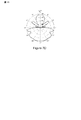
図3Aに、λ/2の素子間隔および2進ビームフォーミング/結合重みをもつ2素子アレイの1対の直交アンテナアレイパターンを示す。この場合のコードブックは、以下の重み行列W
の列によって与えられる直交ビームフォーミング/結合ベクトルの対を備える。第1のビームパターンは0°でその最大値を有し、第2のビームパターンは90°で最大になる。 With orthogonal beamforming / combination vector pairs given by The first beam pattern has its maximum value at 0 ° and the second beam pattern has a maximum at 90 °.
図3Bに、λ/2の素子間隔および2進ビームフォーミング/結合重みを有する3素子線形アレイのアンテナアレイパターンを示す。コードブックは、重み行列
の列によって与えられる3つのビームフォーミング/結合ベクトルを備える。この場合、第1のビームパターンは0°でその最大値を有し、第2のビームパターンは60°および120°で最大になり、第3のパターンは90°で最大になる。 With three beamforming / combination vectors given by In this case, the first beam pattern has its maximum value at 0 °, the second beam pattern has a maximum at 60 ° and 120 °, and the third pattern has a maximum at 90 °.
図3Cでは、λ/2の素子間隔および2進ビームフォーミング/結合重みをもつ4素子線形アレイは、4つの直交ビームパターンを生成する。これらのビームパターンは、以下の重み行列
の列によって与えられるベクトルのコードブックによって特徴付けられる。 Characterized by a vector codebook given by a sequence of
図3Dに、重み行列
の列によって与えられる直交コードブックベクトルに対応する、5素子線形アレイの5つの直交ビームパターンを示す。 Figure 5 shows five orthogonal beam patterns of a five-element linear array corresponding to the orthogonal codebook vector given by
図3Eに、λ/2の素子間隔をもつ6素子線形アレイのビームパターンを示す。直交コードブックベクトルは、以下の重み行列
の列によって与えられる。一代替実施形態では、以下の重み行列
を使用することができる。 Can be used.
図3Fに、λ/2の間隔をもつ7素子線形アレイの直交ビームパターンを示す。ビームパターンは、重み行列
の列によって与えられるコードブックベクトルに対応する。 Corresponds to the codebook vector given by
図3Gに、λ/2の間隔をもつ8素子線形アレイの8つの直交ビームパターンを示す。ビームパターンは、以下の重み行列
の列によって与えられるコードブックベクトルに対応する。 Corresponds to the codebook vector given by
本発明のいくつかの実施形態では、アンテナアレイ重みは、0°、90°、180°および270°のセットからの位相を備えることができる。したがって、クアドラチュア(quadrature)重みは{+1,−1,+j,−j}から選択される。本発明の一実施形態は、I(0°)、−I(180°)、Q(270°)、および−Q(90°)によって特徴付けられる信号の送信および/または受信を提供することができる。信号の等価のセットは、I+Qと、I−Qと、−I+Qと、−I−Qとを備える。 In some embodiments of the present invention, the antenna array weights can comprise phases from a set of 0 °, 90 °, 180 °, and 270 °. Accordingly, quadrature weights are selected from {+1, -1, + j, -j}. One embodiment of the present invention provides for transmission and / or reception of signals characterized by I (0 °), -I (180 °), Q (270 °), and -Q (90 °). it can. The equivalent set of signals comprises I + Q, I-Q, -I + Q, and -I-Q.
図4Aに、λ/2の素子間隔およびクアドラチュアビームフォーミング/結合重みをもつ2素子アレイの4つのアンテナアレイパターンを示す。この場合のコードブックは、以下の重み行列W
の列によって与えられるベクトルのセットを備える。この場合、WWH=4Iである。 With a set of vectors given by In this case, WW H = 4I.
図4Bに、λ/2の素子間隔およびクアドラチュアビームフォーミング/結合重みを使用する3素子アレイの4つのアンテナアレイパターンを示す。コードブックは、以下の重み行列
の列によって与えられるベクトルのセットを備える。この場合も、WWH=4Iである。 With a set of vectors given by Again, WW H = 4I.
図4Cに、λ/2の素子間隔およびクアドラチュアビームフォーミング/結合重みを使用する4素子アレイの4つの直交アンテナアレイパターンを示す。コードブックは、以下の重み行列
の列によって与えられる4つの直交ベクトルのセットを備える。 With a set of four orthogonal vectors given by
図4Dに、クアドラチュア重みおよびλ/2の素子間隔を使用する4素子アレイの代替コードブックに対応するビームパターンを示す。6つのビームフォーミング/結合ベクトルは、重み行列
の列によって与えられる。 Given by a sequence of
4素子アレイの拡張コードブックに対応するビームパターンを図4Eに示す。アレイは、λ/2の間隔をもつ素子およびクアドラチュアビームフォーミング/結合重みを備える。コードブックは、以下の重み行列
の列によって与えられる8つのベクトルのセットを備える。 With a set of 8 vectors given by
図4Fに、λ/2の素子間隔およびクアドラチュアビームフォーミング/結合重みを使用する5素子アレイの6つのアンテナアレイパターンを示す。コードブックは、以下の重み行列
の列によって与えられるベクトルのセットを備える。 With a set of vectors given by
図4Gでは、以下の重み行列
の列によって表されるベクトルのコードブックに従って、λ/2の素子間隔およびクアドラチュアビームフォーミング/結合重みを使用する5素子アレイによって8つのアンテナアレイパターンが生成される。 Eight antenna array patterns are generated by a five-element array using λ / 2 element spacing and quadrature beamforming / combining weights according to the vector codebook represented by
図4Hに、λ/2の素子間隔およびクアドラチュアビームフォーミング/結合重みを使用する6素子アレイの6つの非直交アンテナアレイパターンを示す。コードブックは、以下の重み行列
の列によって与えられる6つのベクトルのセットを備える。 With a set of six vectors given by
図4Iに、λ/2の素子間隔およびクアドラチュアビームフォーミング/結合重みを使用する6素子アレイの8つのアンテナアレイパターンを示す。コードブックは、以下の重み行列
の列によって与えられる8つのベクトルのセットを備え、ただし、WWH=8Iである。 With a set of 8 vectors given by a sequence of WW H = 8I.
図4Jに、λ/2の素子間隔およびクアドラチュアビームフォーミング/結合重みを使用する7素子アレイの8つのアンテナアレイパターンを示す。コードブックは、同じく関係WWH=8Iが成り立つ、以下の重み行列の列によって与えられる8つのベクトルのセットを備える。
図4Kに、λ/2の素子間隔およびクアドラチュアビームフォーミング/結合重みを使用する8素子アレイの8つの直交アンテナアレイパターンを示す。コードブックは、以下の重み行列
の列によって与えられる8つの直交ベクトルのセットを備える。 With a set of eight orthogonal vectors given by
図4Lに、λ/2の素子間隔およびクアドラチュアビームフォーミング/結合重みを使用する8素子アレイの12個のアンテナアレイパターンを示す。コードブックは、以下の重み行列
の列によって与えられる8つのベクトルのセットを備える。 With a set of 8 vectors given by
図4Mに、λ/2の素子間隔およびクアドラチュアビームフォーミング/結合重みを使用する8素子アレイの16個のアンテナアレイパターンを示す。コードブックは、以下の重み行列
の列によって与えられる8つのベクトルのセットを備え、ただし、WWH=16Iである。 With a set of 8 vectors given by a sequence of WW H = 16I.
本発明のいくつかの実施形態は、2〜8個のアンテナ素子(N=2...8)を有するアンテナアレイの、2進(binary)ビームフォーミング/結合重みを使用する擬似オムニおよび相補Golayコードブックを提供することができる。ビームフォーマ重みは、+1または−1である。アンテナ素子上の+1の重みは、+I(正の同相信号)が、そのアンテナ素子上で送信されることを意味し、−1の重みは、−I(負の同相信号)が、そのアンテナ素子上で送信されることを意味する。各コードブックは、擬似オムニパターンの複数のオプションを含むことができる。極性および方位角アンテナ利得パターンに応じて、1つまたは複数の擬似オムニパターンを使用することができる。実相補Golayパターンは、N=2、4、および8の場合にのみ存在する。極性および方位角アンテナ利得パターンに応じて、一方または両方の相補パターンを使用することができる。 Some embodiments of the present invention provide a pseudo omni and complementary Golay using binary beamforming / combining weights for an antenna array with 2-8 antenna elements (N = 2 ... 8). A code book can be provided. The beamformer weight is +1 or -1. A weight of +1 on an antenna element means that + I (positive in-phase signal) is transmitted on that antenna element, and a weight of -1 is -I (negative in-phase signal) It means that it is transmitted on the antenna element. Each codebook can include multiple options of pseudo-omni patterns. Depending on the polarity and azimuth antenna gain pattern, one or more pseudo-omni patterns can be used. Real complementary Golay patterns exist only when N = 2, 4, and 8. Depending on the polarity and azimuth antenna gain pattern, one or both complementary patterns can be used.
2素子アレイの擬似オムニコードブックは、重み行列
の列によって与えられる2つの直交ビームフォーミング(または結合)ベクトルを備える。2つの相補Golayパターンg1(θ,φ)およびg2(θ,φ)、ただし、g1(θ,φ)+g2(θ,φ)=2を図5Aに示す。第1のパターンは、方向0°で最大になり、120.5°のHPBWおよび3.0dBの最大指向性を有する。第2のパターンは、方向90°で最大になり、60.4°のHPBWおよび3.0dBの最大指向性をもつ。 With two orthogonal beamforming (or combination) vectors given by FIG. 5A shows two complementary Golay patterns g 1 (θ, φ) and g 2 (θ, φ), where g 1 (θ, φ) + g 2 (θ, φ) = 2. The first pattern is maximum at 0 ° direction, has HPBW of 120.5 ° and maximum directivity of 3.0 dB. The second pattern is maximal at 90 ° direction and has a HPBW of 60.4 ° and a maximum directivity of 3.0 dB.
3つの擬似直交ビームフォーミング/結合ベクトルを備える3素子アンテナアレイの擬似オムニコードブックは、重み行列W
の列によって与えられる。得られた擬似直交ビームパターンを図5Bに示す。第1のパターンは、方向0°で最大になり、93.4°のHPBWおよび4.77dBの最大指向性を有する。第2のパターンは、方向60°および120°で最大になり、40.4°のHPBWおよび2.2dBの最大指向性をもつ。第3のパターンは、方向90°で最大になり、36.7°のHPBWおよび4.77dBの最大指向性を有する。
Given by a sequence of The obtained pseudo orthogonal beam pattern is shown in FIG. 5B. The first pattern is maximum at 0 ° direction, has a HPBW of 93.4 ° and a maximum directivity of 4.77 dB. The second pattern is maximal in
1対の相補GOLAYパターンg1(θ,φ)+g2(θ,φ)=1.77を図5Cに示す。2つの直交ビームフォーミング/結合ベクトルは、4素子アレイの以下の重み行列
の列によって与えられる。第1のパターンは、方向46°および134°で最大になり、123.0°のHPBWおよび2.48dBの最大指向性を有する。第2のパターンは、方向72°および108°で最大になり、62.9°のHPBWおよび2.48dBの最大指向性をもつ。
Given by a sequence of The first pattern is maximal in
図5Dに、3つの擬似直交ビームフォーミングベクトルを備える5素子アレイのコードブックに対応する3つの擬似直交ビームパターンを示す。コードブックベクトルは、以下の重み行列の列である。
第1のパターンは、方向0°で最大になり、109.3°のHPBWおよび2.55dBの最大指向性をもつ。第2のパターンは、方向54°および126°で最大になり、63.5°のHPBWおよび3.25dBの最大指向性をもつ。第3のパターンは、方向79°および101°で最大になり、43.8°のHPBWおよび3.22dBの最大指向性をもつ。
The first pattern is maximum at
図5Eに、6素子アレイのコードブックに対応する3つの擬似直交ビームパターンを示す。コードブックは、以下の重み行列の列である3つの擬似直交ビームフォーミングベクトルを備える。
この場合、第1のパターンは、方向23°および157°で最大になり、88.2°のHPBWおよび4.30dBの最大指向性をもつ。第2のパターンは、方向57°および123°で最大になり、20.0°のHPBWおよび5.11dBの最大指向性をもつ。第3のパターンは、方向85°および95°で最大になり、32.7°のHPBWおよび4.30dBの最大指向性をもつ。
In this case, the first pattern is maximal in the directions 23 ° and 157 °, with an HPBW of 88.2 ° and a maximum directivity of 4.30 dB. The second pattern is maximal in directions 57 ° and 123 °, with 20.0 ° HPBW and 5.11 dB maximum directivity. The third pattern is maximal in
図5Fに、7素子アレイのコードブックに対応する3つの擬似直交ビームパターンを示す。コードブックは、以下の重み行列の列である3つの擬似直交ビームフォーミングベクトルを備える。
第1のパターンは、133.3°のHPBWおよび2.77dBの最大指向性を有する。第2のパターンは、109.7°のHPBWおよび1.39dBの最大指向性を有する。第3のパターンは、53.8°のHPBWおよび2.77dBの最大指向性を有する。 The first pattern has an HPBW of 133.3 ° and a maximum directivity of 2.77 dB. The second pattern has an HPBW of 109.7 ° and a maximum directivity of 1.39 dB. The third pattern has a HPBW of 53.8 ° and a maximum directivity of 2.77 dB.
8素子アレイの擬似オムニコードブックは、重み行列
の列によって与えられる2つの直交ビームフォーミング(または結合)ベクトルを備える。2つの相補Golayパターンg1(θ,φ)+g2(θ,φ)=2を図5Gに示す。第1のパターンは、方向0°で最大になり、98.7°のHPBWおよび3.0dBの最大指向性を有する。第2のパターンは、方向90°で最大になり、40.9°のHPBWおよび3.0dBの最大指向性をもつ。 With two orthogonal beamforming (or combination) vectors given by Two complementary Golay patterns g 1 (θ, φ) + g 2 (θ, φ) = 2 are shown in FIG. 5G. The first pattern is maximum at 0 ° direction, has 98.7 ° HPBW and 3.0 dB maximum directivity. The second pattern is maximum at 90 ° direction and has 40.9 ° HPBW and 3.0 dB maximum directivity.
クアドラチュア重みを使用する2素子アレイの擬似オムニコードブックは、2進重みが使用される場合と同じである。したがって、コードブックは、重み行列
の列によって与えられる2つの直交ビームフォーミング(または結合)ベクトルを備える。2つの相補Golayパターンg1(θ,φ)およびg2(θ,φ)、ただし、g1(θ,φ)+g2(θ,φ)=2を図6Aに示す。第1のパターンは、方向0°で最大になり、120.5°のHPBWおよび3.0dBの最大指向性を有する。第2のパターンは、方向90°で最大になり、60.4°のHPBWおよび3.0dBの最大指向性をもつ。 With two orthogonal beamforming (or combination) vectors given by FIG. 6A shows two complementary Golay patterns g 1 (θ, φ) and g 2 (θ, φ), where g 1 (θ, φ) + g 2 (θ, φ) = 2. The first pattern is maximum at 0 ° direction, has HPBW of 120.5 ° and maximum directivity of 3.0 dB. The second pattern is maximal at 90 ° direction and has a HPBW of 60.4 ° and a maximum directivity of 3.0 dB.
図6Bに、クアドラチュア重みを使用する3素子アレイの1対の擬似オムニビームパターンを示す。コードブックは、以下の重み行列
中の列の対から導出されるクアドラチュアベクトルの対を備える。1つのパターンは123.6°のHPBWを有し、他のパターンは80.0°のHPBWを有する。両方のパターンは2.22dBの最大指向性を有する。 With a pair of quadrature vectors derived from a pair of middle columns. One pattern has 123.6 ° HPBW and the other has 80.0 ° HPBW. Both patterns have a maximum directivity of 2.22 dB.
図6Cは、クアドラチュア重みをもつ4素子アレイによって生成される2つの相補GOLAYパターンg1(θ,φ)およびg2(θ,φ)のプロットであり、g1(θ,φ)+g2(θ,φ)=2である。この場合の得られた擬似オムニコードブックは、以下の重み行列
の列によって表されるベクトルによって与えられる。第1のパターンは、方向0°で最大になり、83.4°のHPBWおよび3.01dBの最大指向性を有する。第2のパターンは、方向90°で最大になり、29.4°のHPBWおよび3.01dBの最大指向性をもつ。 Given by the vector represented by The first pattern is maximal at 0 ° direction and has a HPBW of 83.4 ° and a maximum directivity of 3.01 dB. The second pattern is maximum at 90 ° direction, with 29.4 ° HPBW and maximum directivity of 3.01 dB.
図6Dに、この場合、擬似オムニコードブックである重みベクトルw=[+1 −1 +1 +1 +1]を使用する5素子アレイによって生成される、2.55dBの最大指向性をもつ擬似オムニパターンを示す。 FIG. 6D shows a pseudo omni pattern with a maximum directivity of 2.55 dB, generated in this case by a five element array using a weight vector w = [+ 1 −1 +1 +1 +1], which is a pseudo omni codebook. .
図7A〜図7Dに、擬似オムニコードブックのベクトルに対応する6素子アレイの擬似オムニビームパターンを示し、各ベクトルは以下の重み行列
の列である。図7Aおよび図7Bに示す擬似オムニビームパターンは2.39dBの最大指向性を有し、図7Cおよび図7Dに示す擬似オムニパターンは2.86dBの最大指向性を有する。 It is a column. The pseudo omni beam pattern shown in FIGS. 7A and 7B has a maximum directivity of 2.39 dB, and the pseudo omni pattern shown in FIGS. 7C and 7D has a maximum directivity of 2.86 dB.
6素子アレイは、図8Aに示す相補GOLAYパターンg1(θ,φ)とg2(θ,φ)との対を生成するように構成され、g1(θ,φ)+g2(θ,φ)=1.93である。直交ビームフォーミング/結合ベクトルの関連する対は、以下の重み行列
の列を備える。第1のパターンは、方向31°および149°で最大になり、120.7°のHPBWおよび2.86dBの最大指向性を有する。第2のパターンは、方向82°および98°で最大になり、61.2°のHPBWおよび2.86dBの最大指向性をもつ。 With columns. The first pattern is maximal in directions 31 ° and 149 °, with HPBW of 120.7 ° and maximum directivity of 2.86 dB. The second pattern is maximal in directions 82 ° and 98 °, with a HPBW of 61.2 ° and a maximum directivity of 2.86 dB.
図8Bに、クアドラチュア重みベクトルもつ7素子アレイからの3つの擬似オムニビームパターンを示す。ベクトルは、擬似オムニコードブックの成分であり、以下の重み行列
の列を含む。最初の2つのパターンの最大指向性は1.39dBであり、第3のパターンの最大指向性は2.77dBである。 Includes a column. The maximum directivity of the first two patterns is 1.39 dB, and the maximum directivity of the third pattern is 2.77 dB.
8素子アレイは、(以下の重み行列の列によって表される)1対のクアドラチュア重みベクトルを備えるコードブックを使用して、図8Cに示す2つの相補ビームパターンを生成することができる。
両方のパターンは3.0dBの最大指向性を有する。1つのパターンは方向0°で最大になり、98.7°のHPBWを有し、他のパターンは方向90°で最大になり、40.9°のHPBWを有する。 Both patterns have a maximum directivity of 3.0 dB. One pattern is maximum at 0 ° direction and has 98.7 ° HPBW, and the other pattern is maximum at 90 ° direction and has 40.9 ° HPBW.
(図8Dおよび図8Eに示す)1対の直交ビームフォーミング/結合ベクトルを、以下の重み行列
を使用して、8素子アレイに対して生成することもできる。 Can also be generated for an 8-element array.
本発明のいくつかの実施形態では、セクタ化アンテナアレイ(SEAA)または切替えアンテナアレイ(SWAA)を使用することができる。N素子SEAAまたはSWAAのコードブックは、単位行列
によって表される。一度にただ1つのアンテナ素子がアクティブであるので、各ビームフォーミングベクトルはただ1つのゼロ以外のエントリ(entry)を有する。 Represented by Since only one antenna element is active at a time, each beamforming vector has only one non-zero entry.
本発明の一実施形態は、アンテナ構成とビームフォーミングに使用される推定アルゴリズム(すなわち、wおよびcを推定する)とから独立している統合メッセージングプロトコルを提供する。メッセージングプロトコルは、送信および受信に使用される様々なアンテナ構成をサポートするように構成できる。そのような構成はフェーズドアレイ(phased array)などのビームフォーミングアンテナアレイを含むことができる。アンテナ構成はセクタ化および切替えアンテナアレイを含むことができる。アンテナ構成は、オムニ(omni)、擬似オムニ、または指向性単一アンテナを含む、様々なビームパターンによって定義できる。メッセージングプロトコルはまた、SASおよびAAS構成をサポートし、プロアクティブおよびオンデマンドビームフォーミングをサポートするように構成できる。一実施形態では、メッセージングプロトコルは、様々なリンクモデル(link model)をサポートするようにさらに構成され、リンクモデルには、(限定はしないが)ピコネットコントローラと複数の加入者デバイスとの間のパケットごとのビームフォーミング、ピコネットコントローラと単一の加入者デバイスとの間のリンク、および加入者デバイス間のピアツーピア(peer-to-peer)リンクが含まれる。 One embodiment of the present invention provides an integrated messaging protocol that is independent of antenna configuration and estimation algorithms used for beamforming (ie, estimating w and c). The messaging protocol can be configured to support various antenna configurations used for transmission and reception. Such a configuration can include a beamforming antenna array, such as a phased array. The antenna configuration can include sectorized and switched antenna arrays. The antenna configuration can be defined by various beam patterns, including omni, pseudo omni, or directional single antenna. The messaging protocol also supports SAS and AAS configurations and can be configured to support proactive and on-demand beamforming. In one embodiment, the messaging protocol is further configured to support various link models, including (but not limited to) packets between a piconet controller and multiple subscriber devices. Per-beamforming, a link between a piconet controller and a single subscriber device, and a peer-to-peer link between subscriber devices.
本発明の実施形態は、プロアクティブビームフォーミングプロトコルとオンデマンドビームフォーミングプロトコルとを含む、実装すべき複数のビームフォーミングプロトコルを提供することができる。プロアクティブビームフォーミングは、(図9に示すような)スーパーフレームのビーコン部分を使用して実行され、ピコネットコントローラが1つまたは複数の加入者デバイスのデータソースであるときに使用される。たとえば、ピコネットコントローラは、キオスク(kiosk)、STB、またはラップトップ(Laptop)コンピュータとすることができ、各パケットを複数の異なる方向のうちの少なくとも1つにおいて宛先デバイスに送信するように構成される。 Embodiments of the present invention can provide multiple beamforming protocols to be implemented, including proactive beamforming protocols and on-demand beamforming protocols. Proactive beamforming is performed using the beacon portion of the superframe (as shown in FIG. 9) and is used when the piconet controller is the data source of one or more subscriber devices. For example, the piconet controller can be a kiosk, STB, or laptop computer and is configured to send each packet to a destination device in at least one of a plurality of different directions. .
オンデマンドビームフォーミングは、2つの加入者デバイス間の送信、またはピコネットコントローラと1つの加入者デバイスとの間の送信に使用できる。オンデマンドビームフォーミングは、トランシーバの対に割り当てられる(図9に示すような)スーパーフレームのチャネル時間割当て(CTA)部分を使用する。両方のビームフォーミングプロトコルでは、擬似オムニ送信は指向性トレーニングセクションの構造に関する情報を伝達し、指向性トレーニングセクションはCSI収集および追跡を可能にする。 On-demand beamforming can be used for transmission between two subscriber devices or between a piconet controller and one subscriber device. On-demand beamforming uses the channel time assignment (CTA) portion of the superframe (as shown in FIG. 9) assigned to a pair of transceivers. In both beamforming protocols, the pseudo-omni transmission conveys information about the structure of the directional training section, which enables CSI collection and tracking.
ピコネットコントローラビーコンは、少なくとも1つの擬似オムニ(Qオムニ)セクションと少なくとも1つの指向性セクションとを備える。一実施形態では、Qオムニセクションは、ピコネットコントローラの周りの異なる(および、場合によっては重なり合う)地理的エリアをカバーする、L個の同じQオムニサブビーコン(Sビーコン)を有する。QオムニSビーコンの集合カバレージは、ピコネットコントローラの周りのターゲット空間をカバーする。各QオムニSビーコンは、Qオムニコードブックから選択される異なるQオムニビームフォーミングパターンを使用して送信される。 The piconet controller beacon comprises at least one pseudo omni (Q omni) section and at least one directional section. In one embodiment, the Q omni section has L identical Q omni sub-beacons (S beacons) covering different (and possibly overlapping) geographic areas around the piconet controller. The collective coverage of Q Omni S beacons covers the target space around the piconet controller. Each Q Omni S beacon is transmitted using a different Q omni beamforming pattern selected from the Q omni codebook.
図9に示す実施形態では、指向性セクションは、トレーニングシーケンスのN回の反復(すなわち、指向性トレーニングセグメントの複数N個)を備えることができ、各反復は、直交(または擬似直交)コードブックからの異なる直交または擬似直交ビームフォーミングベクトルを用いてピコネットコントローラによって送信される。この場合、指向性トレーニングセグメントは、小さいガードインターバル(guard interval)を除いて連続的に送信される。しかしながら、本発明の代替実施形態は、指向性セクション内でのQオムニトレーニングセグメントのインターリービング(inter leaving)(あるいは位置決め)を提供することができる。たとえば、Qオムニトレーニングセグメントは指向性トレーニングセグメントと同じフォーマットを有することができるが、全方向的に送信される。一実施形態では、Qオムニトレーニングセグメントは各指向性トレーニングセグメントの後にくる。CSIの正確な推定値を生成するためにタイミングおよび周波数ドリフトを補償することが必要なので、加入者デバイスは、そのような補償を助けるためにQオムニトレーニングセグメントを使用する。 In the embodiment shown in FIG. 9, the directional section may comprise N iterations of the training sequence (ie, multiple N directional training segments), each iteration being an orthogonal (or quasi-orthogonal) codebook. Transmitted by the piconet controller using different orthogonal or pseudo-orthogonal beamforming vectors from. In this case, the directional training segments are transmitted continuously except for a small guard interval. However, alternative embodiments of the present invention can provide interleaving (or positioning) of Q omni training segments within the directional section. For example, a Q omni training segment can have the same format as a directional training segment, but transmitted omni-directionally. In one embodiment, the Q Omni training segment follows each directional training segment. Because it is necessary to compensate for timing and frequency drift in order to generate an accurate estimate of CSI, the subscriber device uses a Q omni training segment to assist in such compensation.
競合アクセス期間(CAP)は、サブCAP(SCAP)と呼ばれるL個の同じ期間に分割される。L個のSCAPはL個のQオムニビーコンに対応する。l番目のSCAP中に、ピコネットコントローラは、l番目のQオムニビーコン中に送信に使用したQオムニビームフォーマベクトルと同じQオムニビームフォーマベクトルを使用する受信モードにある。 The contention access period (CAP) is divided into L identical periods called sub-CAPs (SCAPs). L SCAPs correspond to L Q omni beacons. During the l th SCAP, the piconet controller is in a receive mode that uses the same Q omni beamformer vector as the Q omni beamformer vector used for transmission during the l th Q omni beacon.
図10Aに、OFDM用のSビーコンのパケット構造を示し、図10Bに、シングルキャリア(SC)シグナリング用のSビーコンのパケット構造を示す。Qオムニビーコンのアンテナ利得に応じて、ピコネットコントローラは、同期の長さ、ヘッダ中のデータ転送速度、およびPSDUフィールドを調整することができる。 FIG. 10A shows the packet structure of an S beacon for OFDM, and FIG. 10B shows the packet structure of an S beacon for single carrier (SC) signaling. Depending on the antenna gain of the Q Omni Beacon, the piconet controller can adjust the length of synchronization, the data rate in the header, and the PSDU field.
オーバーヘッドを低減するために、QオムニSビーコンの数Lを低減することができる。単一アンテナの場合、L=1である。SAAの場合、Lは、セクタ(または切替え)アンテナの数である。ビームフォーミングまたはフェーズドアレイ構成では、Lは、1または2に等しいが、より大きいこともある。送信中に、ピコネットコントローラは、対応する擬似オムニコードブックからのL個の擬似オムニビームフォーミングベクトルを使用し、Qオムニサブビーコン送信ごとに1つのQオムニビームフォーミングベクトルが使用される。 In order to reduce overhead, the number L of Q omni S beacons can be reduced. For a single antenna, L = 1. For SAA, L is the number of sector (or switched) antennas. In a beamforming or phased array configuration, L is equal to 1 or 2, but may be larger. During transmission, the piconet controller uses L pseudo omni beamforming vectors from the corresponding pseudo omni codebook, and one Q omni beamforming vector is used for each Q omni sub-beacon transmission.
本発明の一実施形態では、Qオムニサブビーコンを送信するために1次元のベクトルw=[+1 −1 +j −1 +j +j]Tを使用する、6つの素子をもつ送信フェーズドアレイの場合、L=1である。異なる実施形態では、Nx=4およびNy=3である2次元のフェーズドアンテナアレイの場合、L=2である。第1のQオムニサブビーコンは、ビームフォーミング行列、Wxy,11=wx,1wT y,1を使用して送信され、wx,1=[+1 −j + j −1]T、およびwy,1=[+1 +1 −1]Tである。第2のQオムニサブビーコンは、ビームフォーミング行列、Wxy,21=wx,2wT y,1を使用して送信され、wx,2=[+1 +j +j +1]Tおよびwy,1=[+1 +1 −1]Tである。 In one embodiment of the present invention, for a transmit phased array with 6 elements that uses a one-dimensional vector w = [+ 1 −1 + j −1 + j + j] T to transmit a Q-omni sub-beacon, L = 1. In a different embodiment, L = 2 for a two-dimensional phased antenna array where N x = 4 and N y = 3. The first Q omni sub-beacon is transmitted using a beamforming matrix, W xy, 11 = w x, 1 w T y, 1 , w x, 1 = [+ 1 −j + j −1] T , And wy, 1 = [+ 1 + 1 + 1] T. The second Q omni sub-beacon is transmitted using the beamforming matrix, W xy, 21 = w x, 2 w T y, 1 , w x, 2 = [+ 1 + j + j +1] T and w y, 1 = [+ 1 + 1−1] T
図9に示すフレームの指向性セクションは、トレーニングシーケンスのN回の反復を備える。図11Aに、短いOFDMトレーニングシーケンスを示す。図11Bに、長いOFDMトレーニングシーケンスを示す。図11Cに、短いシングルキャリアトレーニングシーケンスを示す。図11Dに、長いシングルキャリアトレーニングシーケンスを示す。ベクトルu512、v512、およびs512によって示されるシーケンスは、その全体が参照により組み込まれる、2007年11月6日に出願された、仮出願第60/985,957号に記載されている。
The directional section of the frame shown in FIG. 9 comprises N repetitions of the training sequence. FIG. 11A shows a short OFDM training sequence. FIG. 11B shows a long OFDM training sequence. FIG. 11C shows a short single carrier training sequence. FIG. 11D shows a long single carrier training sequence. The sequence indicated by vectors u 512 , v 512 , and s 512 is described in
トレーニングシーケンスは、同期シーケンスsのNs回の反復(Nsは0の場合がある)と、後続のCESフィールドのNc(たとえば、1または2)回の反復とを含む。ピコネットコントローラによって送信される各トレーニングシーケンスは、直交(または擬似直交)コードブックから選択される異なる直交(または擬似直交)ビームパターンを使用する。OFDMおよびシングルキャリアが短いトレーニングシーケンスを使用する場合には、2つの同期シーケンスを自動利得制御(AGC)に使用することができる。さらに、CESフィールドは、CSIを収集するために使用できる。整合フィルタ(matched-filter)受信機は、受信信号を修正Golayシーケンスuおよびvと相関させるように構成されたGolay整合フィルタの出力を整合させ、追加して、完全なチャネル推定値を生成することができる。また、受信機は、完全なノイズ推定値を与える差信号を生成することができる。 The training sequence includes N s iterations of the synchronization sequence s (N s may be 0) and N c (eg, 1 or 2) iterations of the subsequent CES field. Each training sequence transmitted by the piconet controller uses a different orthogonal (or quasi-orthogonal) beam pattern selected from an orthogonal (or quasi-orthogonal) codebook. If OFDM and a single carrier use short training sequences, two synchronization sequences can be used for automatic gain control (AGC). In addition, the CES field can be used to collect CSI. Matched-filter receiver matches and adds the output of a Golay matched filter configured to correlate the received signal with the modified Golay sequences u and v to generate a complete channel estimate Can do. The receiver can also generate a difference signal that gives a complete noise estimate.
一実施形態では、Nx=4およびNy=2をもつビームフォーミングアンテナアレイは、長さ4のx軸コードブック
を使用する。対応する長さ2のy軸コードブックは、
であり、直交ビームフォーミング行列の総数は、J=8、すなわち、Wxy,mn=wx,mwT y,n、ただし、m=1,...,4およびn=1,2である。
この場合、ピコネットコントローラは、J=8のトレーニングシーケンスを送信することによってトレーニングのサイクルを完了し、各トレーニングシーケンスは、ビームフォーミング行列Wxy,11,Wxy,12,...,W xy,42 によって指定される異なる方向において送信される。たとえば、第1のトレーニングシーケンスは、ビームフォーミング行列Wxy,11に対応する方向において送信され、第2のトレーニングシーケンスは、ビームフォーミング行列Wxy,12に対応する方向において送信されるなどである。
In this case, the piconet controller completes the training cycle by sending J = 8 training sequences, where each training sequence is a beamforming matrix W xy, 11 , W xy, 12,. . . , W xy, 42 are transmitted in different directions. For example, the first training sequence is transmitted in the direction corresponding to the beamforming matrix W xy, 11 , the second training sequence is transmitted in the direction corresponding to the beamforming matrix W xy, 12 , and so on.
いくつかの実施形態では、ピコネットコントローラは、利用可能なビームフォーミング行列のサブセットのみを使用するように構成できる。たとえば、ピコネットコントローラは、限定された角度の範囲(たとえば、360°の代わりに、180°)にわたって送信することができる。ピコネットコントローラは、加入者デバイスをトレーニングするために使用することができる、可能なビームフォーミング行列のサブセットである指向性コードブックを使用する。指向性コードブックのサイズがJである場合、対応するJ個の方向におけるJ個のトレーニングシーケンスの送信をサイクルと呼ぶ。いくつかの実施形態では、L個の同じQオムニSビーコンは、ピコネットコントローラによって選択されるコードブックベクトルのインデックスを含むことができる。QオムニSビーコンはまた、スーパーフレーム当たりのサイクルの数および/またはサイクル当たりのスーパーフレームの数を伝達することができる。 In some embodiments, the piconet controller can be configured to use only a subset of the available beamforming matrices. For example, the piconet controller can transmit over a limited range of angles (eg, 180 ° instead of 360 °). The piconet controller uses a directional codebook that is a subset of possible beamforming matrices that can be used to train subscriber devices. If the size of the directional codebook is J, transmission of J training sequences in the corresponding J directions is called a cycle. In some embodiments, the L same Q omni S beacons may include an index of a codebook vector selected by the piconet controller. The Q Omni S beacon can also convey the number of cycles per superframe and / or the number of superframes per cycle.
図12Aに、M個のサイクルを備えるスーパーフレームを示し、図12Bに、M個のスーパーフレームごとに生じるサイクルを示す。加入者デバイスは、ピコネットコントローラからのQオムニ送信をリッスンするように構成される。検出時に、加入者デバイスは、指向性セクションの構造を得るためにQオムニSビーコンの成分を復号する。加入者デバイスは、そのアンテナを第1の方向に向けるために第1のコードブックベクトルを選択する。加入者デバイスは、そのアンテナを第2の方向に向けるために第2のコードブックベクトルを選択し、この手順を各コードブックベクトルに対して繰り返すことができる。代替的に、加入者デバイスは、コードブックのサブセットからコードブックベクトルを選択することができる。加入者デバイスはCSI行列、H、を計算して、ピコネットコントローラの最適ビームフォーミング重みと加入者デバイス自体の最適結合ベクトルとを推定する。SAS場合には、加入者デバイスは、適切なリンク品質を与えると考える重みの組合せを決定するまでQオムニ送信をリッスンすることができる。得られたビームフォーミング重みはピコネットコントローラに送信される。 FIG. 12A shows a superframe with M cycles, and FIG. 12B shows a cycle that occurs every M superframes. The subscriber device is configured to listen for Q omni transmissions from the piconet controller. Upon detection, the subscriber device decodes the components of the Q Omni S beacon to obtain the structure of the directional section. The subscriber device selects the first codebook vector to point its antenna in the first direction. The subscriber device can select a second codebook vector to point its antenna in the second direction and repeat this procedure for each codebook vector. Alternatively, the subscriber device can select a codebook vector from a subset of the codebook. The subscriber device calculates the CSI matrix, H, to estimate the optimal beamforming weight of the piconet controller and the optimal coupling vector of the subscriber device itself. In the case of SAS, the subscriber device can listen for Q omni transmissions until it determines the combination of weights that it considers to provide adequate link quality. The obtained beamforming weight is transmitted to the piconet controller.
図13Aに、トレーニングシーケンス情報と、送信および受信アンテナに関するアンテナアレイ情報と、アンテナタイプと、QオムニSビーコン識別子と、QオムニSビーコンの数とを備える伝送フレームのビームフォーミング情報要素を示す。アンテナタイプは、ピコネットコントローラアンテナ(たとえば、単一アンテナ、ビームフォーミングアレイ、フェーズドアレイ、SEAA、SWAA)と、SASまたはAASアンテナ構成と、送信および受信側にクアドラチュア重みが使用されるか2進重みが使用されるかとに関する情報を含むことができる。ビームフォーミング情報要素のフィールドは様々なアンテナ構成に適合できる。たとえば、トレーニングシーケンス情報およびアンテナアレイ情報は、単一アンテナ構成または切替えアンテナアレイでは省略できる。 FIG. 13A shows a beamforming information element of a transmission frame comprising training sequence information, antenna array information regarding transmit and receive antennas, antenna type, Q omni S beacon identifier, and number of Q omni S beacons. Antenna types include piconet controller antennas (eg, single antenna, beamforming array, phased array, SEAA, SWAA), SAS or AAS antenna configurations, and quadrature weights on the transmit and receive sides or binary weights Can contain information about what is used. The field of the beamforming information element can be adapted to various antenna configurations. For example, training sequence information and antenna array information can be omitted for single antenna configurations or switched antenna arrays.
図13Bに、ビームフォーミング情報要素のアンテナアレイ情報部分を示す。この情報は、2次元アレイの場合のx軸に沿ったアンテナの数Nxと、x軸に沿って使用されるコードブックのIDと、y軸に沿ったアンテナの数Nyと、y軸に沿って使用されるコードブックのIDとを含むことができる。いくつかの実施形態では、x軸に沿って使用すべきビームフォーミングベクトルのサブセットのサイズJxおよびIDと、y軸に沿って使用すべきビームフォーミングベクトルのサブセットのサイズJyおよびIDとを含むことができる。 FIG. 13B shows the antenna array information portion of the beamforming information element. This information includes the number N x of antennas along the x-axis in the case of two-dimensional array, the ID of the codebook used along the x-axis, the number N y of the antenna along the y-axis, y-axis IDs of codebooks used along the lines. In some embodiments, includes a beam forming vector subset size J x and ID to be used along the x axis and a beam forming vector subset size J y and ID to be used along the y axis. be able to.
図13Cに、32×Tc(Tcは、チップまたはサンプリング継続時間)を単位にしたガードインターバル継続時間と、CES反復の数Ncと、同期反復の数Nsと、トレーニングシーケンス反復の数とを含む、ビームフォーミング情報要素のトレーニングシーケンス情報部分を示す。 FIG. 13C shows the guard interval duration in units of 32 × T c (T c is the chip or sampling duration), the number of CES iterations N c , the number of synchronization iterations N s, and the number of training sequence iterations The training sequence information part of the beamforming information element including
図16Aに、プロアクティブビームフォーミングを実行するための方法を示す。ピコネットコントローラは、数LのQオムニSビーコンとスーパーフレーム当たりの数Nの指向性トレーニングシーケンスとを送信(1601)する。加入者デバイスは、QオムニSビーコンの少なくとも1つをリッスンし、復号(1602)して、指向性セクションに関係する情報を収集する。本発明の一実施形態では、加入者デバイスはQオムニSビーコンのセット全体をリッスンすることができる。加入者デバイスは、直交(または擬似直交)コードブックの適切なサブセットを選択(1603)し、選択された結合ベクトルを使用して走査手順を開始する。 FIG. 16A shows a method for performing proactive beamforming. The piconet controller transmits a number L of Q Omni S beacons and a number N of directional training sequences per superframe (1601). The subscriber device listens for and decodes (1602) at least one of the Q Omni S beacons to collect information related to the directional section. In one embodiment of the present invention, the subscriber device can listen to the entire set of Q Omni S beacons. The subscriber device selects (1603) the appropriate subset of the orthogonal (or quasi-orthogonal) codebook and initiates the scanning procedure using the selected combination vector.
一実施形態では、加入者デバイスは、コードブックからのベクトルを使用して特定の方向に向き、送信されたサイクルをリッスンするとき、リンク品質ファクタ(LQF)を記憶することができる。このプロセスは、加入者デバイスが、所定のしきい値を上回るl番目のLQFを発見するまで、または、すべてのコードブックベクトルをリッスンし終え、CSI行列を収集するまで繰り返される。 In one embodiment, a subscriber device may store a link quality factor (LQF) when listening in a transmitted direction and using a vector from a codebook in a particular direction. This process is repeated until the subscriber device finds the lth LQF above a predetermined threshold, or has finished listening to all codebook vectors and has collected the CSI matrix.
加入者デバイスは、その最適結合ベクトルc2とピコネットコントローラの最適ビームフォーミングベクトルw1とを推定(1604)する。推定された最適ビームフォーミングベクトルw1(および随意に、最適結合ベクトルc2)を、l番目のSCAP中にピコネットコントローラにフィードバック(1605)する。 Subscriber device, the optimum combining vector c 2 and piconet controller optimal beamforming vector w 1 and the estimated for 1604. The estimated optimal beamforming vector w 1 (and optionally the optimal combining vector c 2 ) is fed back (1605) to the piconet controller during the l-th SCAP.
SASの場合には、加入者デバイスとピコネットコントローラは、CTAP中にデータパケットを交換(1606)する。加入者デバイスは、ビーコンを周期的に走査することによって、ビームフォーミングおよび結合ベクトルを追跡(1607)する。加入者デバイスは、wおよびcに対する更新を周期的にフィードバック(1608)する。 In the case of SAS, the subscriber device and the piconet controller exchange (1606) data packets during CTAP. The subscriber device tracks (1607) the beamforming and combining vectors by periodically scanning the beacons. The subscriber device periodically feedbacks (1608) updates to w and c.
AASの場合には、ステップ1606〜1608はバイパスされる。代わりに、双方向ビームフォーミングを完了するために、通信リンクに割り当てられたCTAP中にオンデマンドビームフォーミングを使用することができる。図16Bに示すように、ピコネットコントローラは、その最適結合ベクトルc1と加入者デバイスの最適ビームフォーミングベクトルw2とを推定するために、アップリンクCSI、H2→1(n)、ただし、n=0、1,...,N−1を収集(1616)し、次いで、少なくともビームフォーミング重みベクトルw2を加入者デバイスに伝達(1617)する。収集が完了すると、加入者デバイスは、ピコネットコントローラがw2およびc1を追跡し、更新することができるように、低頻度の「指向性収集期間(directional acquisition period)」(たとえば、数マイクロ秒ごとに1回)を送信(1618)する。更新レート(追跡レート)は、システムが許容可能な最大ドップラー(Doppler)に依存する。60GHzにおいて歩行者速度が3m/sの場合、ドップラー周波数はfd=600Hzであり、コヒーレンス(coherence)時間は約0.3msであるので、0.3msごとに1回以下の更新レートが可能である。
In the case of AAS, steps 1606 to 1608 are bypassed. Alternatively, on-demand beamforming can be used during CTAP assigned to the communication link to complete bidirectional beamforming. As shown in FIG. 16B, the piconet controller is responsible for the uplink CSI, H 2 → 1 (n), where n to estimate its optimal combining vector c 1 and the optimal beamforming vector w 2 of the subscriber device. = 0, 1,. . . , N−1 are collected (1616), and then at least the beamforming weight vector w 2 is communicated to the subscriber device (1617). When the acquisition is complete, the subscriber device can have a low frequency “directional acquisition period” (eg, a few microseconds) so that the piconet controller can track and update w 2 and
(2つの加入者デバイス間、またはピコネットコントローラと1つの加入者デバイスとの間で実行される)オンデマンドビームフォーミングは、図14Aに示すスーパーフレームのチャネル時間割当て(CTA)部分を使用する。図17Aは、本発明の一実施形態によるSAS用のオンデマンドビームフォーミング方法の流れ図である。各トランシーバが他の(1つまたは複数の)トランシーバのアンテナアレイ処理能力(たとえば、アレイ素子の数、アンテナ素子重みの範囲など)を知るように、アソシエーション(association)中にアンテナ情報を交換(1701)する。第1のトランシーバが第2のトランシーバにQオムニSビーコンを送信するとき、擬似オムニ収集(1702)を実行する。第1のトランシーバが第2のトランシーバに指向性トレーニングシーケンスを送信するとき、指向性収集(1703)を実行する。収集が完了すると、システムは、第1のトランシーバが第2のトランシーバにデータを送信するとき、追跡(1704)を実行する。 On-demand beamforming (performed between two subscriber devices or between a piconet controller and one subscriber device) uses the channel time allocation (CTA) portion of the superframe shown in FIG. 14A. FIG. 17A is a flowchart of an on-demand beamforming method for SAS according to an embodiment of the present invention. Exchange antenna information during association (1701) so that each transceiver knows the antenna array processing capabilities (eg, number of array elements, range of antenna element weights, etc.) of the other transceiver (s) ) When the first transceiver sends a Q Omni S beacon to the second transceiver, a pseudo omni collection (1702) is performed. When the first transceiver sends a directional training sequence to the second transceiver, directional collection (1703) is performed. When the collection is complete, the system performs tracking (1704) when the first transceiver transmits data to the second transceiver.
図17Bに、本発明の一実施形態によるAAS用のオンデマンドビームフォーミング方法のステップを示す。アソシエーション中にアンテナ情報を交換(1701)する。第1のトランシーバが第2のトランシーバにQオムニSビーコンを送信するとき、擬似オムニ収集(1702)を実行する。第1のトランシーバが第2のトランシーバに指向性トレーニングシーケンスを送信するとき、指向性収集(1703)を実行する。第2のトランシーバが第1のトランシーバにQオムニSビーコンを送信するとき、擬似オムニ収集(1712)を実行する。同様に、第2のトランシーバが第1のトランシーバに指向性トレーニングシーケンスを送信するとき、指向性収集(1713)を実行する。両方向において収集が完了すると、システムは、第1のトランシーバが第2のトランシーバにデータを送信するとき、および/または第2のトランシーバが第1のトランシーバにデータを送信するとき、追跡(1714)を実行する。 FIG. 17B shows the steps of an on-demand beamforming method for AAS according to one embodiment of the present invention. Exchange (1701) antenna information during association. When the first transceiver sends a Q Omni S beacon to the second transceiver, a pseudo omni collection (1702) is performed. When the first transceiver sends a directional training sequence to the second transceiver, directional collection (1703) is performed. When the second transceiver sends a Q Omni S beacon to the first transceiver, a pseudo omni collection (1712) is performed. Similarly, directivity collection (1713) is performed when the second transceiver sends a directivity training sequence to the first transceiver. When acquisition is complete in both directions, the system tracks (1714) when the first transceiver transmits data to the second transceiver and / or when the second transceiver transmits data to the first transceiver. Run.
図14Bに、本発明の一実施形態による擬似オムニ収集シグナリングプロトコルを示す。(図14Aに示す)CTAフレーム中で、第1のトランシーバは、ビームフォーミング情報要素を搬送する数Lの擬似オムニパケットを送信する。L個の送信の各々の後に、L個のリスニング期間(ACK)が続く。第1のトランシーバは、L個のリスニング期間の1つ(たとえばl番目のリスニング期間)においてACKを受信するまで、この構造を反復し続ける。これ以降、第1のトランシーバは、Qオムニコードブックから送信のためのl番目のQオムニ方向(SASの場合には、受信方向でもある)を選択する。第2のトランシーバは、その最良のQオムニ受信方向(SASの場合には、最良の送信方向でもある)を記録し、それを将来のQオムニ受信に使用する。AASの場合には、第2のトランシーバが第1のトランシーバに送信するとき、プロセスを繰り返す。 FIG. 14B illustrates a pseudo omni collection signaling protocol according to one embodiment of the present invention. In the CTA frame (shown in FIG. 14A), the first transceiver transmits a number L of pseudo omni packets carrying beamforming information elements. Each of the L transmissions is followed by L listening periods (ACKs). The first transceiver continues to repeat this structure until it receives an ACK in one of the L listening periods (eg, the lth listening period). Thereafter, the first transceiver selects the l-th Q omni direction for transmission from the Q omni codebook (which is also the reception direction in the case of SAS). The second transceiver records its best Q omni reception direction (which in the case of SAS is also the best transmission direction) and uses it for future Q omni reception. In the case of AAS, the process repeats when the second transceiver transmits to the first transceiver.
図15に、第1のトランシーバから第2のトランシーバへの周期的送信を使用する指向性トレーニングのフレームフォーマットを示し、図18Aに、そのフレームフォーマットを使用する本発明の一実施形態による方法を示す。指向性収集期間は、リスニング期間が後続する随意のQオムニパケットを備えることができる。第1のトランシーバによって送信される指向性トレーニングシーケンスの1つのサイクルは、選択されたコードブックのサブセットからのすべてのJ個の直交(擬似直交)ビームフォーミングベクトルに対応する。各サイクルの後には、第2のトランシーバからのフィードバックをリッスンするためのリスニング期間(ACK)が続く。 FIG. 15 illustrates a directional training frame format using periodic transmission from a first transceiver to a second transceiver, and FIG. 18A illustrates a method according to an embodiment of the present invention that uses the frame format. . The directional collection period may comprise an optional Q omni packet followed by a listening period. One cycle of the directional training sequence transmitted by the first transceiver corresponds to all J orthogonal (pseudo-orthogonal) beamforming vectors from the selected subset of codebooks. Each cycle is followed by a listening period (ACK) to listen for feedback from the second transceiver.
第2のトランシーバが、CSI、H1→2(n)、ただし、n=0,1,...,N−1を収集するか、または適切なリンク品質インジケータ(LQI)を発見(1802)するまで、第1のトランシーバは期間を反復(1801)する。第2のトランシーバは、好適w1およびc2を推定(1803)し、リスニング(ACK)期間中に少なくともw1推定値を第1のトランシーバに結合(1804)する。好適ビームフォーミングベクトルw1は、トランシーバのコードブックベクトルの1つであるか、またはコードブックベクトルの線形結合であるか、またはトランシーバのコードブックベクトルとは無関係なこともある。 The second transceiver is CSI, H 1 → 2 (n), where n = 0, 1,. . . , N-1 or until a suitable link quality indicator (LQI) is found (1802), the first transceiver repeats the period (1801). The second transceiver estimates (1803) the preferred w 1 and c 2 and couples (1804) at least the w 1 estimate to the first transceiver during the listening (ACK) period. The preferred beamforming vector w 1 is one of the transceiver codebook vectors, or a linear combination of the codebook vectors, or may be independent of the transceiver codebook vector.
以下の重み行列
によって表されるコードブックをもつ4素子アレイを使用する一実施形態では、コードブックは、ベクトル[1 −1 1 −1]、[1 −j −1 j]、[1 1 1 1]、および[1 j −1 −j]のうちの1つまたは複数を備えることができる。最適ビームフォーミング/結合ベクトルがコードブックベクトルの1つから選択される場合、実施形態はビーム切替え(beam-switching)と呼ばれる。 In one embodiment using a four-element array having a codebook represented by: [1 -1 1 -1], [1 -j -1 j], [1 1 1 1], and One or more of [1 j −1 -j] may be provided. If the optimal beamforming / combining vector is selected from one of the codebook vectors, the embodiment is called beam-switching.
一実施形態では、最適ビームフォーミング/結合ベクトルは、4素子アレイに対する可能な重み組合せのいずれかから選択される。クアドラチュア重みが使用される場合(すなわち、重み±1および±j)、ベクトルを選択するための44個の可能な組合せがある。本発明の一実施形態は、フェーザを備える重みから最適ビームフォーミング/結合ベクトルを選択することを提供する。別の実施形態では、様々な振幅および位相を備える重みを使用することができる。 In one embodiment, the optimal beamforming / combination vector is selected from any of the possible weight combinations for a four element array. If quadrature weights are used (i.e., weight ± 1 and ± j), there are 4 four possible combinations for choosing vectors. One embodiment of the present invention provides for selecting an optimal beamforming / combination vector from weights comprising phasors. In another embodiment, weights with different amplitudes and phases can be used.
トランシーバは、データ通信中にビームフォーミングおよび結合のためにw1およびc2推定値を使用する。いずれかまたは両方のトランシーバは、第1のトランシーバが指向性収集期間を送信するとき、推定値w1およびc2を更新(1805)する。 The transceiver uses the w 1 and c 2 estimates for beamforming and combining during data communication. Either or both transceivers update (1805) the estimated values w 1 and c 2 when the first transceiver transmits a directional collection period.
AASの場合には、図18Bに示す追加のステップが実行される。第2のトランシーバは、第1のトランシーバに指向性トレーニングシーケンスを送信(1811)し、第1のトランシーバは、CSI、H2→1を収集(または適切なLQIを決定)(1812)する。第1のトランシーバは、w2およびc1を推定(1813)し、少なくともw2推定値を第2のトランシーバに結合(1814)する。推定値w1およびc2は、データ送信中にビームフォーミングおよび結合重みとして使用され、第2のトランシーバが指向性収集期間を送信するとき、これらの推定値w1およびc2を周期的に更新(1815)する。 For AAS, the additional steps shown in FIG. 18B are performed. The second transceiver sends a directional training sequence to the first transceiver (1811), and the first transceiver collects CSI, H 2 → 1 (or determines an appropriate LQI) (1812). The first transceiver, estimating the w 2 and c 1 and (1813), at least w 2 estimates coupled to a second transceiver to (1814). Estimates w 1 and c 2 are used as beamforming and combining weights during data transmission, and periodically update these estimates w 1 and c 2 when the second transceiver transmits a directional acquisition period. (1815).
本発明の範囲は、本明細書で説明するアレイ処理実施形態に限定されるものと解釈すべきではない。そうではなく、本出願人らは、代替実施形態が、特定の軸に沿った9つ以上の素子をもつアンテナアレイと、複数の偏波をもつアンテナを備えるアンテナアレイとを備えることができること、およびそのようなアンテナアレイ構成が本発明の範囲および趣旨内に入ることを予想する。一実施形態では、擬似オムニパターンを生成するために、直交直線偏波(orthogonal liner polarization)をもつ2つのダイポールアンテナを一緒に使用することができる。 The scope of the present invention should not be construed as limited to the array processing embodiments described herein. Rather, Applicants have that alternative embodiments can comprise an antenna array with nine or more elements along a particular axis and an antenna array with antennas with multiple polarizations, And such antenna array configurations are expected to fall within the scope and spirit of the present invention. In one embodiment, two dipole antennas with orthogonal linear polarization can be used together to generate a pseudo-omni pattern.
本発明の装置および方法実施形態は、様々なハードウェアおよびソフトウェアを使用して実装できることを諒解されたい。たとえば、本発明の実施形態によるビームフォーミング、結合、および関連する適用例は、特定用途向け集積回路(ASIC)およびゲートアレイなどのプログラマブル(programmable)論理デバイスなど、専用のハードウェア、および/または、マイクロプロセッサ、マイクロコントローラまたはデジタル信号プロセッサ(DSP)などのコンピューティングデバイス上で実行するソフトウェアまたはファームウェアを使用して実施できる。また、ビームフォーミング/結合重み計算および選択の機能を単一のASICなどの単一のデバイスに統合することができるが、それらの機能をいくつかのデバイス間に分散することもできることを諒解されよう。 It should be appreciated that the apparatus and method embodiments of the present invention can be implemented using a variety of hardware and software. For example, beamforming, combining, and related applications according to embodiments of the present invention include dedicated hardware, such as programmable logic devices such as application specific integrated circuits (ASICs) and gate arrays, and / or It can be implemented using software or firmware running on a computing device such as a microprocessor, microcontroller or digital signal processor (DSP). It will also be appreciated that the beamforming / joint weight calculation and selection functions can be integrated into a single device, such as a single ASIC, but those functions can also be distributed among several devices. .
本発明は好ましい実施形態に限定されるものではない。さらに、本明細書で説明する方法および装置実施形態は、ハードウェア、ソフトウェア、ファームウェア、またはそれらの様々な組合せにおける実装形態を含む様々な方法で実装できることを、当業者なら認識するはずである。そのようなハードウェアの例は、ASIC、フィールドプログラマブルゲートアレイ、汎用プロセッサ、DSP、および/または他の回路を含むことができる。本発明のソフトウェアおよび/またはファームウェア実装形態は、Java(登録商標)、C、C++、Matlab(登録商標)、Verilog、VHDLを含むプログラミング言語、および/またはプロセッサ固有のマシン語およびアセンブリ言語の任意の組合せによって実装できる。 The present invention is not limited to the preferred embodiments. Moreover, those skilled in the art will recognize that the method and apparatus embodiments described herein can be implemented in a variety of ways, including implementations in hardware, software, firmware, or various combinations thereof. Examples of such hardware can include ASICs, field programmable gate arrays, general purpose processors, DSPs, and / or other circuits. The software and / or firmware implementation of the present invention can be any programming language, including Java®, C, C ++, Matlab®, Verilog, VHDL, and / or processor-specific machine and assembly languages. Can be implemented by combination.
本発明の方法実施形態を実行するために、様々なデジタルコンピュータシステム構成を使用することができ、特定のシステム構成は、本発明の方法実施形態を実行することが可能である限り、本明細書で開示する本発明の代表的なシステム実施形態と等価であり、本発明の範囲および趣旨内である。 Various digital computer system configurations can be used to perform the method embodiments of the present invention, and as long as a particular system configuration is capable of performing the method embodiments of the present invention, And is equivalent to the exemplary system embodiment of the present invention disclosed in, and within the scope and spirit of the present invention.
デジタルコンピュータシステムが、本発明の方法実施形態を実装するプログラムソフトウェアからの命令に従って特定の機能を実行するようにプログラムされると、そのようなデジタルコンピュータシステムは、事実上、本発明の方法実施形態に特有の専用コンピュータになる。このプログラミングに必要な技法はコンピュータシステムの当業者によく知られている。 When a digital computer system is programmed to perform a particular function in accordance with instructions from program software that implements the method embodiments of the present invention, such digital computer systems are effectively method embodiments of the present invention. It becomes a special computer peculiar to. The techniques required for this programming are well known to those skilled in the computer system arts.
本発明の様々な実施形態は、システム構成、および方法が実行されるステップの順序の変更を含むことができる。多くの場合、複数のステップおよび/または複数の構成要素を統合することができる。 Various embodiments of the invention can include changing the system configuration and the order of steps in which the method is performed. In many cases, multiple steps and / or multiple components can be integrated.
本明細書で説明する方法およびシステム実施形態は、本発明の特定の実施形態を例示するにすぎない。本明細書では明示的に説明または図示していないが、本発明の原理を実施し、その趣旨および範囲内に含まれる様々な構成を、当業者なら考案することができることを諒解されたい。さらに、本明細書に記載するすべての例および条件付き言語は、読者が本発明の原理を理解するのを助けるための教育学的なものにすぎない。本開示およびその関連する言及は、そのような明確に記載する例および条件に限定されないものと解釈すべきである。さらに、本発明の原理、態様、および実施形態、ならびに本発明の特定の例を記載する本明細書のすべての記述は、本発明の構造的均等物と機能的均等物の両方を包含するものする。さらに、そのような均等物は、現在知られている均等物ならびに将来開発される均等物の両方、すなわち、構造にかかわらず同じ機能を実行する開発されるどんな要素をも含むものとする。 The method and system embodiments described herein are merely illustrative of specific embodiments of the invention. Although not explicitly described or illustrated herein, it should be understood that those skilled in the art can devise various configurations that implement the principles of the invention and fall within the spirit and scope thereof. Moreover, all examples and conditional languages described herein are merely pedagogical to help the reader understand the principles of the invention. The present disclosure and its related references should not be construed as limited to such specifically set forth examples and conditions. Moreover, all statements herein reciting principles, aspects, and embodiments of the invention, as well as specific examples of the invention, include both structural and functional equivalents of the invention. To do. In addition, such equivalents are intended to include both currently known equivalents as well as equivalents developed in the future, i.e., any element developed that performs the same function regardless of structure.
本明細書のブロック図は、本発明の原理を実施する例示的な回路、アルゴリズム、および機能ステップの概念図を表すことを、当業者なら諒解されよう。同様に、フローチャート、流れ図、信号図、システム図、コードなどは、コンピュータ可読媒体で実質的に表現でき、コンピュータまたはプロセッサが明示的に図示されているか否かにかかわらず、そのようなコンピュータまたはプロセッサによってそのように実行される、様々なプロセスを表すことを諒解されたい。 Those skilled in the art will appreciate that the block diagrams herein represent conceptual diagrams of exemplary circuits, algorithms, and functional steps that implement the principles of the invention. Similarly, flowcharts, flowcharts, signal diagrams, system diagrams, code, etc. can be substantially represented on a computer-readable medium, whether or not such computer or processor is explicitly illustrated. Should be understood to represent the various processes so performed.
「プロセッサ」または「システム」と標示される機能ブロックを含む、図面に示す様々な要素の機能は、専用ハードウェア、ならびに適切なソフトウェアに関連してソフトウェアを実行することが可能なハードウェアの使用によって与えられる。プロセッサによって与えられる場合、機能は、単一の専用プロセッサ、共有プロセッサ、または、そのいくつかが共有できる複数の個々のプロセッサによって与えられる。さらに、「プロセッサ」または「コントローラ」という用語の明示的使用は、ソフトウェアを実行することが可能なハードウェアをもっぱら指すと解釈すべきではなく、限定はしないが、デジタル信号プロセッサ(DSP)ハードウェア、ソフトウェアを記憶するための読取り専用メモリ(ROM)、ランダムアクセスメモリ(RAM)、および不揮発性記憶装置を暗示的に含むことができる。従来型および/またはカスタムの他のハードウェアも含めることができる。同様に、本明細書で説明する構成要素またはデバイスの機能は、プログラム論理の動作、専用論理、プログラム制御と専用論理との対話によって、さらには手作業で実行でき、特定の技法は、文脈からより具体的に理解されるように、実装者によって選択可能である。 The functions of the various elements shown in the drawings, including the functional blocks labeled "processor" or "system", are dedicated hardware as well as the use of hardware capable of executing software in conjunction with appropriate software. Given by. When provided by a processor, functionality is provided by a single dedicated processor, shared processor, or multiple individual processors some of which can be shared. Further, the explicit use of the terms “processor” or “controller” should not be construed to refer solely to hardware capable of executing software, but is not limited to, digital signal processor (DSP) hardware. , Implicitly including read only memory (ROM), random access memory (RAM), and non-volatile storage for storing software. Other conventional and / or custom hardware can also be included. Similarly, the functions of the components or devices described herein can be performed by program logic operations, dedicated logic, program control and dedicated logic interactions, or even manually, and specific techniques can be derived from context. As can be understood more specifically, it can be selected by the implementer.
本明細書で、指定された機能を実行するための手段として表される要素は、たとえば、その機能を実行する回路要素の組合せ、または機能を実行するためにソフトウェアを実行するための適切な回路と組み合わせられた、任意の形態のソフトウェア、したがって、ファームウェア、マイクロコードなどを含めて、その機能を実行するどんな方法をも包含するものとする。本明細書で説明する本発明の実施形態は、様々な記載された手段によって与えられる機能が、動作説明が必要とする方法で組み合わせられ、まとめられるということに存する。本出願人は、それらの機能を与えることができるいかなる手段も、本明細書に示す手段と等価であると考える。
以下に本件出願当初の特許請求の範囲に記載された発明を付記する。
[C1]
第1のトランシーバと第2のトランシーバとの間のビームフォーミング方法であって、少なくともビームフォーミングコードブックのサブセットを使用する信号を前記第1のトランシーバから前記第2のトランシーバに送信することによってチャネル状態情報(CSI)を収集することと、前記CSIを収集するために少なくとも結合コードブックのサブセットを使用するように前記第2のトランシーバを構成することと、推定された最適ビームフォーミングベクトルと推定された最適結合ベクトルとを生成するために前記CSIからの最適ビームフォーミングベクトルと最適結合ベクトルとを推定することと、少なくとも前記推定された最適ビームフォーミングベクトルと前記推定された最適結合ベクトルとのうちの1つを前記第1のトランシーバに送信することとを備える方法。
[C2]
推定することが最適性基準のセットの少なくとも1つの最適性基準を使用し、前記セットが実効信号対雑音比(SNR)と平均SNRとを備える、C1に記載の方法。
[C3]
前記CSIを収集するために使用されたレートよりも低いレートで前記ビームフォーミングコードブックの前記サブセットを送信することによって前記CSIが収集された後、前記CSIの更新を行うことと、前記推定ステップおよび前記送信ステップを反復することとをさらに備える、C1に記載の方法。
[C4]
前記ビームフォーミングコードブックおよび前記結合コードブックが、重みベクトルのセットのうちの少なくとも1つを備え、前記セットが、少なくとも1つの2進重みベクトルと、少なくとも1つのクアドラチュア重みベクトルとを備える、C1に記載の方法。
[C5]
前記ビームフォーミングコードブックおよび前記結合コードブックが、コードブックのセットのうちの少なくとも1つを備え、前記セットが、擬似オムニコードブックと相補Golayコードブックとを備える、C1に記載の方法。
[C6]
C1に記載の方法を実行するように構成されたピコネットコントローラ。
[C7]
C1に記載の方法を実行するように構成された、ピコネット中の加入者デバイス。
[C8]
ビームフォーミング重みと結合重みとを選択するために第1のトランシーバと少なくとも第2のトランシーバとの間でシグナリングするためのフレームフォーマットを使用するための方法であって、前記第1のトランシーバから前記第2のトランシーバに信号を送信することであって、前記信号が複数の送信セグメントを備え、前記複数の送信セグメントの各々が、所定のビームフォーミングコードブックからの異なるビームパターンを用いて送信される、送信することと、前記少なくとも第2のトランシーバからのフィードバックをリッスンすることと、前記少なくとも第2のトランシーバからのフィードバックに基づいてセットのうちの少なくとも1つのベクトルを選択することであって、前記セットが、ビームフォーミング重みと結合重みとのうちの少なくとも1つを備える、選択することとを備える方法。
[C9]
前記信号を送信することが、擬似オムニセクションと指向性セクションのとのうちの少なくとも1つを送信することを備える、C8に記載の方法。
[C10]
プロアクティブビームフォーミングとオンデマンドビームフォーミングとのうちの少なくとも1つを実行するようにさらに構成された、C8に記載の方法。
[C11]
前記所定のビームフォーミングコードブックが、擬似オムニコードブックと相補Golayコードブックとのうちの少なくとも1つを備える、C8に記載の方法。
[C12]
前記所定のビームフォーミングコードブックが、擬似オムニコードブックと相補Golayコードブックとのうちの少なくとも1つのサブセットを備える、C8に記載の方法。
[C13]
リッスンすることが、複数のリスニングセグメントにわたってリッスンするために複数の結合ベクトルを使用することを備え、前記複数の結合ベクトルが前記ビームフォーミングコードブックのベクトルであり、前記複数の結合ベクトルの各々が、前記複数の送信セグメントの各々に対応する、C8に記載の方法。
[C14]
前記信号が、擬似オムニサブビーコンと指向性トレーニングシーケンスとのうちの少なくとも1つを備える、C8に記載の方法。
[C15]
C8に記載の方法を実行するように構成されたピコネットコントローラ。
[C16]
アンテナアレイを備える第2のトランシーバに通信可能に結合されたアンテナアレイを備える少なくとも第1のトランシーバのためにビームフォーミング重みと結合重みとを選択するための方法であって、前記第1のワイヤレストランシーバによって送信された信号を前記第2のトランシーバにおいて受信することであって、前記信号が複数の送信セグメントを備え、前記複数の送信セグメントの各々が、所定のビームフォーミングコードブックからの異なるビームパターンを用いて送信される、受信することと、少なくとも前記複数の送信セグメントのサブセットから前記第1のトランシーバの好適ビームフォーミングベクトルを推定することと、前記第2のトランシーバの好適結合ベクトルを推定することと、リスニング期間中に前記好適ビームフォーミングベクトルと前記好適結合ベクトルとのうちの少なくとも1つを前記第1のトランシーバに送信することとを備える方法。
[C17]
前記好適ビームフォーミングベクトルを推定することと、前記好適結合ベクトルを推定することとのうちの少なくとも1つが、チャネル状態情報を収集することと、リンク品質インジケータを計算することとのうちの少なくとも1つを備える、C16に記載の方法。
[C18]
前記好適結合ベクトルを推定することが、複数の整合フィルタ出力を生成するために前記信号を複数のGolayシーケンスと相関させることと、チャネル推定値を生成するために前記整合フィルタ出力を結合することを備える、C16に記載の方法。
[C19]
前記リスニング期間が、複数のリスニング期間セグメントを備え、前記複数のリスニング期間セグメントの各々が前記複数の送信セグメントの1つに対応し、送信することが、前記推定された好適ビームフォーミングベクトルに対応する前記送信セグメントの特定の1つに対応する前記複数のリスニング期間セグメントの特定の1つを選択するようにさらに構成された、C16に記載の方法。
[C20]
プロアクティブビームフォーミングとオンデマンドビームフォーミングとのうちの少なくとも1つを実行するように構成された、C16に記載の方法。
[C21]
前記信号が、擬似オムニサブビーコンと指向性トレーニングシーケンスとのうちの少なくとも1つを備える、C16に記載の方法。
[C22]
前記好適ビームフォーミングベクトルを推定することが、前記第1のトランシーバに対応する制約の第1のセットを使用し、前記好適結合ベクトルを推定することが、前記第2のトランシーバに対応する制約の第2のセットを使用する、C16に記載の方法。
[C23]
前記好適ビームフォーミングベクトルおよび前記好適結合ベクトルが、複数の位相と複数の振幅とのうちの少なくとも1つを備える、C16に記載の方法。
[C24]
前記第1のトランシーバの前記アンテナアレイと前記第2のトランシーバの前記アンテナアレイとのうちの少なくとも1つが複数のアンテナを備え、前記複数のアンテナの各々が異なる偏波を有する、C16に記載の方法。
[C25]
C16に記載の方法を実行するように構成された、ピコネット中で動作する加入者デバイス。
As used herein, an element represented as a means for performing a specified function is, for example, a combination of circuit elements that perform the function, or a suitable circuit for executing software to perform the function. Any form of software combined with, and thus any method of performing that function, including firmware, microcode, etc. The embodiments of the invention described herein reside in that the functions provided by the various described means are combined and grouped together in a manner that requires an operational description. Applicants consider that any means that can provide those functions is equivalent to the means presented herein.
The invention described in the scope of the claims at the beginning of the present application is added below.
[C1]
A beamforming method between a first transceiver and a second transceiver, the channel state being transmitted from the first transceiver to the second transceiver using a signal that uses at least a subset of the beamforming codebook. Collecting information (CSI), configuring the second transceiver to use at least a subset of the combined codebook to collect the CSI, and estimating an estimated optimal beamforming vector Estimating an optimal beamforming vector and an optimal combining vector from the CSI to generate an optimal combining vector, and at least one of the estimated optimal beamforming vector and the estimated optimal combining vector; The first tiger How and a sending to the receiver.
[C2]
The method of C1, wherein estimating uses at least one optimality criterion of the set of optimality criteria, the set comprising an effective signal to noise ratio (SNR) and an average SNR.
[C3]
Updating the CSI after the CSI has been collected by transmitting the subset of the beamforming codebook at a rate lower than the rate used to collect the CSI; and The method of C1, further comprising repeating the transmitting step.
[C4]
The beamforming codebook and the combined codebook comprise at least one of a set of weight vectors, the set comprising at least one binary weight vector and at least one quadrature weight vector. The method described in 1.
[C5]
The method of C1, wherein the beamforming codebook and the combined codebook comprise at least one of a set of codebooks, and the set comprises a pseudo omni codebook and a complementary Golay codebook.
[C6]
A piconet controller configured to perform the method of C1.
[C7]
A subscriber device in a piconet configured to perform the method of C1.
[C8]
A method for using a frame format for signaling between a first transceiver and at least a second transceiver to select a beamforming weight and a combining weight, the method comprising: Transmitting a signal to two transceivers, wherein the signal comprises a plurality of transmission segments, each of the plurality of transmission segments being transmitted using a different beam pattern from a predetermined beamforming codebook. Transmitting, listening for feedback from the at least second transceiver, and selecting at least one vector of the set based on feedback from the at least second transceiver, the set Is combined with beamforming weights Comprising at least one of Mito, a method and a selecting.
[C9]
The method of C8, wherein transmitting the signal comprises transmitting at least one of a pseudo omni section and a directional section.
[C10]
The method of C8, further configured to perform at least one of proactive beamforming and on-demand beamforming.
[C11]
The method of C8, wherein the predetermined beamforming codebook comprises at least one of a pseudo omnicodebook and a complementary Golay codebook.
[C12]
The method of C8, wherein the predetermined beamforming codebook comprises at least a subset of a pseudo omnicodebook and a complementary Golay codebook.
[C13]
Listening comprises using a plurality of combination vectors to listen across a plurality of listening segments, wherein the plurality of combination vectors are vectors of the beamforming codebook, and each of the plurality of combination vectors includes: The method of C8, corresponding to each of the plurality of transmission segments.
[C14]
The method of C8, wherein the signal comprises at least one of a pseudo omni sub-beacon and a directional training sequence.
[C15]
A piconet controller configured to perform the method of C8.
[C16]
A method for selecting beamforming weights and coupling weights for at least a first transceiver comprising an antenna array communicatively coupled to a second transceiver comprising an antenna array, the first wireless transceiver At the second transceiver, wherein the signal comprises a plurality of transmission segments, each of the plurality of transmission segments having a different beam pattern from a predetermined beamforming codebook. Transmitting using, estimating a preferred beamforming vector of the first transceiver from at least a subset of the plurality of transmit segments, and estimating a preferred combining vector of the second transceiver. , During the listening period How and a transmitting at least one of said preferred combining vector and the beamforming vector to the first transceiver.
[C17]
At least one of estimating the preferred beamforming vector and estimating the preferred combining vector is at least one of collecting channel state information and calculating a link quality indicator. The method of C16, comprising:
[C18]
Estimating the preferred combining vector comprises correlating the signal with a plurality of Golay sequences to generate a plurality of matched filter outputs and combining the matched filter outputs to generate a channel estimate. The method of C16, comprising.
[C19]
The listening period comprises a plurality of listening period segments, each of the plurality of listening period segments corresponding to one of the plurality of transmission segments, and transmitting corresponds to the estimated preferred beamforming vector. The method of C16, further configured to select a particular one of the plurality of listening period segments corresponding to the particular one of the transmission segments.
[C20]
The method of C16, configured to perform at least one of proactive beamforming and on-demand beamforming.
[C21]
The method of C16, wherein the signal comprises at least one of a pseudo omni sub-beacon and a directional training sequence.
[C22]
Estimating the preferred beamforming vector uses a first set of constraints corresponding to the first transceiver, and estimating the preferred combining vector includes a first set of constraints corresponding to the second transceiver. The method of C16, wherein two sets are used.
[C23]
The method of C16, wherein the preferred beamforming vector and the preferred combining vector comprise at least one of a plurality of phases and a plurality of amplitudes.
[C24]
The method of C16, wherein at least one of the antenna array of the first transceiver and the antenna array of the second transceiver comprises a plurality of antennas, each of the plurality of antennas having a different polarization. .
[C25]
A subscriber device operating in a piconet configured to perform the method of C16.
Claims (24)
少なくともビームフォーミングコードブックのサブセットを使用する信号を前記第1のトランシーバから前記第2のトランシーバに送信し、前記第2のトランシーバからのチャネル状態情報(CSI)についてのフィードバック情報を受信することによって前記CSIを収集することであって、前記信号を送信することが指向性セクションと、前記指向性セクションの構造に関する情報を持つ擬似オムニセクションとのうちの少なくとも1つを送信することを備える、収集することと、
推定された最適ビームフォーミングベクトルと推定された最適結合ベクトルとを生成するために前記CSIからの最適ビームフォーミングベクトルと最適結合ベクトルとを推定することと、
少なくとも前記推定された最適ビームフォーミングベクトルと前記推定された最適結合ベクトルとのうちの1つを前記第2のトランシーバに送信することと
を備える方法。 A beamforming method between a first transceiver and a second transceiver, comprising:
Wherein by at least sends a signal to use a subset of the beamforming codebook from the first transceiver to the second transceiver receives feedback information about the channel state information (CSI) from the second transceiver Collecting CSI , wherein transmitting the signal comprises transmitting at least one of a directional section and a pseudo-omni section having information regarding a structure of the directional section; And
Estimating an optimal beamforming vector and an optimal combined vector from the CSI to generate an estimated optimal beamforming vector and an estimated optimal combined vector;
Transmitting at least one of the estimated optimal beamforming vector and the estimated optimal combining vector to the second transceiver .
少なくともビームフォーミングコードブックのサブセットを使用する信号をトランシーバに送信し、前記トランシーバからのチャネル状態情報(CSI)についてのフィードバック情報を受信することによって前記CSIを収集するための手段であって、前記信号を送信することが指向性セクションと、前記指向性セクションの構造に関する情報を持つ擬似オムニセクションとのうちの少なくとも1つを送信することを備える、収集するための手段と、
推定された最適ビームフォーミングベクトルと推定された最適結合ベクトルとを生成するために前記CSIからの最適ビームフォーミングベクトルと最適結合ベクトルとを推定するための手段と、
少なくとも前記推定された最適ビームフォーミングベクトルと前記推定された最適結合ベクトルとのうちの1つを前記トランシーバに送信するための手段と、
を備えるピコネットコントローラ。 A piconet controller that executes a beamforming method ,
Means for collecting said CSI by transmitting a signal using at least a subset of a beamforming codebook to a transceiver and receiving feedback information about channel state information (CSI) from said transceiver, comprising: Means for collecting, comprising: transmitting at least one of a directional section and a pseudo omni section having information regarding a structure of the directional section;
Means for estimating an optimal beamforming vector and an optimal combined vector from the CSI to generate an estimated optimal beamforming vector and an estimated optimal combined vector;
Means for transmitting at least one of the estimated optimal beamforming vector and the estimated optimal combining vector to the transceiver;
A piconet controller equipped with.
チャネル状態情報(CSI)を収集する為に少なくとも結合コードブックのサブセット使用するように構成された前記加入者デバイスにトランシーバから送信された信号を受信する為の手段であって、前記信号は、指向性セクションと、前記指向性セクションの構造に関する情報を持つ擬似オムニセクションとのうちの少なくとも1つを備える、受信する為の手段と、
推定された最適ビームフォーミングベクトルと推定された最適結合ベクトルとを生成するために前記CSIからの最適ビームフォーミングベクトルと最適結合ベクトルとを推定するための手段と、
少なくとも前記推定された最適ビームフォーミングベクトルと前記推定された最適結合ベクトルとのうちの1つを前記トランシーバに送信するための手段と、
を備えるピコネット中の加入者デバイス。 A subscriber device in a piconet performing beamforming ,
Means for receiving a signal transmitted from a transceiver to the subscriber device configured to use at least a subset of the combined codebook to collect channel state information (CSI), the signal being directed Means for receiving comprising at least one of a sex section and a pseudo omni section having information regarding the structure of the directional section;
Means for estimating an optimal beamforming vector and an optimal combined vector from the CSI to generate an estimated optimal beamforming vector and an estimated optimal combined vector;
Means for transmitting at least one of the estimated optimal beamforming vector and the estimated optimal combining vector to the transceiver;
A subscriber device in a piconet comprising:
前記第1のトランシーバから前記第2のトランシーバに信号を送信することであって、前記信号が複数の送信セグメントを備え、前記複数の送信セグメントの各々が、所定のビームフォーミングコードブックからの異なるビームパターンを用いて送信され、前記信号を送信することが指向性セクションと、前記指向性セクションの構造に関する情報を持つ擬似オムニセクションとのうちの少なくとも1つを送信することを備える、送信することと、
前記少なくとも第2のトランシーバからのフィードバックをリッスンすることと、
前記少なくとも第2のトランシーバからの前記フィードバックに基づいてセットのうちの少なくとも1つのベクトルを選択することであって、前記セットが、ビームフォーミング重みと結合重みとのうちの少なくとも1つを備える、選択することと、
を備える方法。 A method for using a frame format for signaling between a first transceiver and at least a second transceiver to select a beamforming weight and a combining weight, comprising:
Transmitting a signal from the first transceiver to the second transceiver, the signal comprising a plurality of transmission segments, each of the plurality of transmission segments being a different beam from a predetermined beamforming codebook. Transmitting using a pattern, wherein transmitting the signal comprises transmitting at least one of a directional section and a pseudo omni section having information regarding a structure of the directional section ; ,
Listening for feedback from the at least second transceiver;
Selecting at least one vector of a set based on the feedback from the at least second transceiver, the set comprising at least one of a beamforming weight and a combining weight To do
A method comprising:
トランシーバに信号を送信するための手段であって、前記信号が複数の送信セグメントを備え、前記複数の送信セグメントの各々が、所定のビームフォーミングコードブックの中の異なるビームパターンを用いて送信され、前記信号を送信することが指向性セクションと、前記指向性セクションの構造に関する情報を持つ擬似オムニセクションとのうちの少なくとも1つを送信することを備える、送信するための手段と、
少なくとも前記トランシーバからのフィードバックをリッスンするための手段と、
少なくとも前記トランシーバからの前記フィードバックに基づいてセットのうちの少なくとも1つのベクトルを選択するための手段であって、前記セットが、ビームフォーミング重みと結合重みとのうちの少なくとも1つを備える、選択するための手段と、
を備えるピコネットコントローラ。 A piconet controller performing a method for using a frame format for signaling between a piconet controller and at least one transceiver to select beamforming weights and combining weights , comprising:
Means for transmitting a signal to a transceiver, wherein the signal comprises a plurality of transmission segments, each of the plurality of transmission segments being transmitted using a different beam pattern in a predetermined beamforming codebook; Means for transmitting, wherein transmitting the signal comprises transmitting at least one of a directional section and a pseudo omni section having information regarding a structure of the directional section;
Means for listening for feedback from at least the transceiver;
Means for selecting at least one vector of a set based on at least the feedback from the transceiver, the set comprising at least one of a beamforming weight and a combining weight Means for
A piconet controller equipped with.
前記第1のトランシーバによって送信された信号を第2のトランシーバにおいて受信することであって、前記信号が所定のビームフォーミングコードブックの中のビームパターンに結び付けられた複数の送信セグメントを備え、前記信号が指向性セクションと、前記指向性セクションの構造に関する情報を持つ擬似オムニセクションとのうちの少なくとも1つを備える、受信することと、
少なくとも前記複数の送信セグメントのサブセットから前記第1のトランシーバの好適ビームフォーミングベクトルを推定することと、
前記第2のトランシーバの好適結合ベクトルを推定することと、
リスニング期間中に前記好適ビームフォーミングベクトルと前記好適結合ベクトルとのうちの少なくとも1つを前記第1のトランシーバに送信することと、
を備える方法。 A method for selecting beamforming weights and joint weights for at least a first transceiver comprising :
Wherein the signals transmitted by the first transceiver comprising: receiving at the second transceiver, comprising a plurality of transmission segments tied to beam pattern in said signal a predetermined beamforming codebook, the signal Receiving comprises: at least one of a directional section and a pseudo omni section having information about the structure of the directional section ;
Estimating a preferred beamforming vector of the first transceiver from at least a subset of the plurality of transmit segments;
Estimating a preferred combining vector of the second transceiver;
Transmitting at least one of the preferred beamforming vector and the preferred combining vector to the first transceiver during a listening period;
A method comprising:
前記トランシーバによって送信された信号を受信するための手段であって、前記信号が所定のビームフォーミングコードブックの中のビームパターンに結び付けられた複数の送信セグメントを備え、前記信号が指向性セクションと、前記指向性セクションの構造に関する情報を持つ擬似オムニセクションとのうちの少なくとも1つを備える、受信するための手段と、
少なくとも前記複数の送信セグメントのサブセットから前記トランシーバの好適ビームフォーミングベクトルを推定するための手段と、
前記加入者デバイスの好適結合ベクトルを推定するための手段と、
リスニング期間中に前記好適ビームフォーミングベクトルと前記好適結合ベクトルとのうちの少なくとも1つを前記トランシーバに送信するための手段と、
を備えるピコネット中で動作する加入者デバイス。 A subscriber device operating in a piconet that performs a method for selecting beamforming weights and combining weights for at least a transceiver comprising :
Means for receiving a signal transmitted by the transceiver, the signal comprising a plurality of transmit segments coupled to a beam pattern in a predetermined beamforming codebook, wherein the signal is a directional section; Means for receiving comprising at least one of a pseudo omni section having information regarding the structure of the directional section;
Means for estimating a preferred beamforming vector of the transceiver from at least a subset of the plurality of transmit segments;
Means for estimating a preferred combining vector of the subscriber device;
Means for transmitting at least one of the preferred beamforming vector and the preferred combining vector to the transceiver during a listening period;
A subscriber device that operates in a piconet.
Applications Claiming Priority (3)
| Application Number | Priority Date | Filing Date | Title |
|---|---|---|---|
| US11/960,234 | 2007-12-19 | ||
| US11/960,234 US7916081B2 (en) | 2007-12-19 | 2007-12-19 | Beamforming in MIMO systems |
| PCT/US2008/087094 WO2009085792A1 (en) | 2007-12-19 | 2008-12-17 | Beamforming in mimo systems |
Publications (2)
| Publication Number | Publication Date |
|---|---|
| JP2011508527A JP2011508527A (en) | 2011-03-10 |
| JP5242700B2 true JP5242700B2 (en) | 2013-07-24 |
Family
ID=40512533
Family Applications (1)
| Application Number | Title | Priority Date | Filing Date |
|---|---|---|---|
| JP2010539723A Active JP5242700B2 (en) | 2007-12-19 | 2008-12-17 | Beamforming in MIMO systems |
Country Status (8)
| Country | Link |
|---|---|
| US (1) | US7916081B2 (en) |
| EP (1) | EP2243226B1 (en) |
| JP (1) | JP5242700B2 (en) |
| KR (2) | KR101407016B1 (en) |
| CN (1) | CN101904109B (en) |
| ES (1) | ES2417604T3 (en) |
| TW (1) | TW200935791A (en) |
| WO (1) | WO2009085792A1 (en) |
Families Citing this family (252)
| Publication number | Priority date | Publication date | Assignee | Title |
|---|---|---|---|---|
| US6757659B1 (en) * | 1998-11-16 | 2004-06-29 | Victor Company Of Japan, Ltd. | Audio signal processing apparatus |
| US8400356B2 (en) * | 2006-12-27 | 2013-03-19 | Lockheed Martin Corp. | Directive spatial interference beam control |
| JP5258307B2 (en) * | 2007-01-19 | 2013-08-07 | パナソニック株式会社 | Wireless communication method and wireless communication apparatus |
| US7929918B2 (en) * | 2007-08-13 | 2011-04-19 | Samsung Electronics Co., Ltd. | System and method for training the same type of directional antennas that adapts the training sequence length to the number of antennas |
| US8917675B2 (en) * | 2007-08-20 | 2014-12-23 | Samsung Electronics Co., Ltd. | System and method for multiple contention access periods |
| US8254359B2 (en) * | 2007-12-21 | 2012-08-28 | Intel Corporation | Recursive reduction of channel state feedback |
| KR101424280B1 (en) * | 2008-01-23 | 2014-07-31 | 엘지전자 주식회사 | A method for transmitting a signal in a multiple input multiple output system |
| US8165595B2 (en) * | 2008-01-25 | 2012-04-24 | Samsung Electronics Co., Ltd. | System and method for multi-stage antenna training of beamforming vectors |
| US8280445B2 (en) | 2008-02-13 | 2012-10-02 | Samsung Electronics Co., Ltd. | System and method for antenna training of beamforming vectors by selective use of beam level training |
| US8902822B2 (en) * | 2008-03-11 | 2014-12-02 | Intel Corporation | Arrangements for association and re-association in a wireless network |
| US8532001B2 (en) * | 2008-03-11 | 2013-09-10 | Intel Corporation | Beaconing and frame structure for directional antenna communications |
| CN101983490A (en) * | 2008-04-02 | 2011-03-02 | 诺基亚公司 | Method and apparatus in relaying system |
| US8212722B2 (en) * | 2008-04-30 | 2012-07-03 | Samsung Electronics Co., Ltd. | System and method for discovering and tracking communication directions with asymmetric antenna systems |
| JP5031670B2 (en) * | 2008-06-02 | 2012-09-19 | 株式会社日立製作所 | Transmitting apparatus, base station, and symbol transmitting method |
| US8478204B2 (en) * | 2008-07-14 | 2013-07-02 | Samsung Electronics Co., Ltd. | System and method for antenna training of beamforming vectors having reuse of directional information |
| US8854252B2 (en) * | 2008-09-12 | 2014-10-07 | Propagation Research Associates, Inc. | Multi-mode, multi-static interferometer utilizing pseudo orthogonal codes |
| JP5645238B2 (en) * | 2008-09-19 | 2014-12-24 | 日本電気株式会社 | Wireless communication system control method and wireless communication system |
| WO2010037100A1 (en) | 2008-09-29 | 2010-04-01 | Marvell World Trade Ltd. | Physical layer data unit format |
| US8817676B2 (en) * | 2008-11-03 | 2014-08-26 | Samsung Electronics Co., Ltd. | Method and system for station-to-station directional wireless communication |
| US8116819B2 (en) * | 2008-12-31 | 2012-02-14 | Intel Corporation | Arrangements for beam refinement in a wireless network |
| US8068844B2 (en) | 2008-12-31 | 2011-11-29 | Intel Corporation | Arrangements for beam refinement in a wireless network |
| US8335167B1 (en) | 2009-02-02 | 2012-12-18 | Marvell International Ltd. | Refining beamforming techniques for phased-array antennas |
| US8830917B1 (en) * | 2009-02-04 | 2014-09-09 | Marvell International Ltd. | Short preamble in a physical layer data unit |
| JP5141587B2 (en) * | 2009-02-13 | 2013-02-13 | ソニー株式会社 | COMMUNICATION DEVICE, COMMUNICATION CONTROL METHOD, AND COMMUNICATION SYSTEM |
| JP5251605B2 (en) * | 2009-03-02 | 2013-07-31 | ソニー株式会社 | Communication apparatus and gain control method |
| TWI517620B (en) * | 2009-03-17 | 2016-01-11 | 皇家飛利浦電子股份有限公司 | Method and apparatus for communicating in a mimo network |
| KR101719977B1 (en) * | 2009-06-09 | 2017-03-27 | 엘지전자 주식회사 | Method of controlling network in wireless network and device |
| US8208427B2 (en) * | 2009-07-10 | 2012-06-26 | Qualcomm Incorporated | Multiple peer-to-peer signaling |
| US20110007721A1 (en) * | 2009-07-10 | 2011-01-13 | Qualcomm Incorporated | Method for directional association |
| US8406247B2 (en) * | 2009-07-10 | 2013-03-26 | Qualcomm Incorporated | Multiple peer-to-peer signaling |
| WO2011038555A1 (en) * | 2009-09-30 | 2011-04-07 | 华为技术有限公司 | Method, terminal and base station for processing channel state information |
| US8625693B2 (en) * | 2009-11-06 | 2014-01-07 | Samsung Electronics Co., Ltd. | Techniques for transformation codebook antenna beamforming in OFDM wireless communication system |
| US8750401B2 (en) * | 2009-12-16 | 2014-06-10 | Electronics And Telecommunications Research Institute | Sequential transmission multi-beamforming method with low complexity using Hadamard matrix |
| US9401753B2 (en) * | 2009-12-23 | 2016-07-26 | Intel Corporation | Native medium access control support for beamforming |
| US9059760B2 (en) * | 2010-02-05 | 2015-06-16 | Qualcomm Incorporated | Apparatus and method for enabling uplink beamforming transit diversity |
| WO2011105936A1 (en) * | 2010-02-23 | 2011-09-01 | Telefonaktiebolaget L M Ericsson (Publ) | Communication performance guidance in a user terminal |
| JP5321508B2 (en) * | 2010-03-11 | 2013-10-23 | ソニー株式会社 | COMMUNICATION DEVICE, COMMUNICATION CONTROL METHOD, AND COMMUNICATION SYSTEM |
| US9806789B2 (en) | 2010-04-06 | 2017-10-31 | Samsung Electronics Co., Ltd. | Apparatus and method for spatial division duplex (SDD) for millimeter wave communication system |
| EP2384075A1 (en) * | 2010-04-30 | 2011-11-02 | France Telecom | Method and system for scheduling radio links by means of spatial reuse |
| CN102377467B (en) * | 2010-08-23 | 2015-02-04 | 中国移动通信集团公司 | Eight-antenna downlink control channel sending method and device |
| CN101945063B (en) * | 2010-09-21 | 2014-04-09 | 北京交通大学 | Method and system for estimating ultra-wideband channel of MB-OFDM (Multiband-Orthogonal Frequency Division Multiplexing) system |
| KR101872690B1 (en) * | 2010-10-21 | 2018-06-29 | 엘지전자 주식회사 | Method and device for generating precoding matrix in wireless communication system |
| KR101806311B1 (en) | 2011-03-04 | 2017-12-07 | 삼성전자주식회사 | Network mimo communication system of using regularized beamforing |
| US20120230380A1 (en) * | 2011-03-11 | 2012-09-13 | Fraunhofer-Gesellschaft Zur Foerderung Der Angewandten Forschung E. V. | Method for determining beamforming parameters in a wireless communication system and to a wireless communication system |
| US8981993B2 (en) | 2011-04-27 | 2015-03-17 | Telefonaktiebolaget L M Ericsson (Publ) | Beamforming methods and apparatuses |
| US9585083B2 (en) * | 2011-06-17 | 2017-02-28 | Samsung Electronics Co., Ltd. | Apparatus and method for supporting network entry in a millimeter-wave mobile broadband communication system |
| AU2012287609B2 (en) * | 2011-07-28 | 2017-02-23 | Samsung Electronics Co., Ltd. | Apparatus and method for beamforming in wireless communication system |
| CN102307165B (en) * | 2011-08-29 | 2015-04-22 | 北京邮电大学 | Channel parameter estimation method and system |
| US9054767B2 (en) | 2011-09-27 | 2015-06-09 | Futurewei Technologies, Inc. | Robust transceiver design |
| US9537546B2 (en) | 2011-12-08 | 2017-01-03 | Intel Corporation | Implementing MIMO in mmWave wireless communication systems |
| US20130229309A1 (en) * | 2012-03-01 | 2013-09-05 | Nokia Siemens Networks Oy | Beam alignment method utilizing omni-directional sounding and use thereof |
| CN104205694A (en) | 2012-03-02 | 2014-12-10 | 日本电气株式会社 | Channel estimation method and receiver |
| KR20130127347A (en) * | 2012-05-10 | 2013-11-22 | 삼성전자주식회사 | Method and apparatus for communication on analog and digital hybrid beam-forming |
| US9444140B2 (en) | 2012-05-23 | 2016-09-13 | Intel Corporation | Multi-element antenna beam forming configurations for millimeter wave systems |
| US9275690B2 (en) | 2012-05-30 | 2016-03-01 | Tahoe Rf Semiconductor, Inc. | Power management in an electronic system through reducing energy usage of a battery and/or controlling an output power of an amplifier thereof |
| US8953726B2 (en) | 2012-06-01 | 2015-02-10 | Qualcomm Incorporated | Antenna selection technique for fast diversity |
| WO2014003499A1 (en) * | 2012-06-29 | 2014-01-03 | Samsung Electronics Co., Ltd. | Method and apparatus for beamforming |
| US9509351B2 (en) | 2012-07-27 | 2016-11-29 | Tahoe Rf Semiconductor, Inc. | Simultaneous accommodation of a low power signal and an interfering signal in a radio frequency (RF) receiver |
| CN103780357B (en) * | 2012-10-23 | 2017-08-11 | 华为技术有限公司 | The feedback method and relevant apparatus and system of a kind of weight matrix |
| US10009065B2 (en) | 2012-12-05 | 2018-06-26 | At&T Intellectual Property I, L.P. | Backhaul link for distributed antenna system |
| US9113347B2 (en) | 2012-12-05 | 2015-08-18 | At&T Intellectual Property I, Lp | Backhaul link for distributed antenna system |
| KR102027914B1 (en) | 2013-01-08 | 2019-10-02 | 삼성전자주식회사 | Method and apparatus for adaptive inter-cell interference canellation for wireless communication system |
| EP2949091B1 (en) * | 2013-01-25 | 2018-10-24 | MediaTek Singapore Pte Ltd. | Sectorization feedback and multi-sector transmission in wireless networks |
| US9722310B2 (en) | 2013-03-15 | 2017-08-01 | Gigpeak, Inc. | Extending beamforming capability of a coupled voltage controlled oscillator (VCO) array during local oscillator (LO) signal generation through frequency multiplication |
| US9666942B2 (en) | 2013-03-15 | 2017-05-30 | Gigpeak, Inc. | Adaptive transmit array for beam-steering |
| US9780449B2 (en) | 2013-03-15 | 2017-10-03 | Integrated Device Technology, Inc. | Phase shift based improved reference input frequency signal injection into a coupled voltage controlled oscillator (VCO) array during local oscillator (LO) signal generation to reduce a phase-steering requirement during beamforming |
| US9531070B2 (en) | 2013-03-15 | 2016-12-27 | Christopher T. Schiller | Extending beamforming capability of a coupled voltage controlled oscillator (VCO) array during local oscillator (LO) signal generation through accommodating differential coupling between VCOs thereof |
| US9716315B2 (en) | 2013-03-15 | 2017-07-25 | Gigpeak, Inc. | Automatic high-resolution adaptive beam-steering |
| US9184498B2 (en) | 2013-03-15 | 2015-11-10 | Gigoptix, Inc. | Extending beamforming capability of a coupled voltage controlled oscillator (VCO) array during local oscillator (LO) signal generation through fine control of a tunable frequency of a tank circuit of a VCO thereof |
| US9837714B2 (en) | 2013-03-15 | 2017-12-05 | Integrated Device Technology, Inc. | Extending beamforming capability of a coupled voltage controlled oscillator (VCO) array during local oscillator (LO) signal generation through a circular configuration thereof |
| WO2014158208A1 (en) * | 2013-03-29 | 2014-10-02 | Intel Corporation | Orthogonal beamforming for multiple user multiple-input and multiple-output (mu-mimo) |
| US9999038B2 (en) | 2013-05-31 | 2018-06-12 | At&T Intellectual Property I, L.P. | Remote distributed antenna system |
| US9525524B2 (en) | 2013-05-31 | 2016-12-20 | At&T Intellectual Property I, L.P. | Remote distributed antenna system |
| WO2015016963A1 (en) * | 2013-08-01 | 2015-02-05 | Fujitsu Limited | Terminal clustering |
| US9014311B1 (en) * | 2013-10-15 | 2015-04-21 | Nokia Solutions And Networks Oy | Interleaved multi-beam acquisition waveform providing concurrent beam selection, automatic gain control (AGC) and automatic frequency correction (AFC) |
| CN105814932B (en) * | 2013-10-20 | 2019-10-15 | A·S·帕布拉 | Radio reception device |
| US8897697B1 (en) | 2013-11-06 | 2014-11-25 | At&T Intellectual Property I, Lp | Millimeter-wave surface-wave communications |
| EP3084982A4 (en) * | 2013-12-16 | 2017-10-25 | Intel Corporation | User equipment and method for assisted three dimensional beamforming |
| US9331767B1 (en) * | 2015-02-09 | 2016-05-03 | Nokia Solutions And Networks Oy | Translation of basis functions for feedback in a wireless network |
| CN103916174B (en) * | 2014-03-27 | 2017-01-18 | 西安空间无线电技术研究所 | Method for forming wave beam by combining spacial domain and polarization domain in frequency division duplex system |
| CN105227273B (en) * | 2014-07-02 | 2019-09-17 | 电信科学技术研究院 | A kind of method, system and the equipment of data transmission |
| US9270354B1 (en) * | 2014-07-08 | 2016-02-23 | Hrl Laboratories, Llc | Blind beamforming using knowledge embedded in transmitted signals |
| KR102187855B1 (en) | 2014-07-31 | 2020-12-07 | 삼성전자 주식회사 | Apparatus and method for cell measuring in a beam formed system |
| US9692101B2 (en) | 2014-08-26 | 2017-06-27 | At&T Intellectual Property I, L.P. | Guided wave couplers for coupling electromagnetic waves between a waveguide surface and a surface of a wire |
| US9768833B2 (en) | 2014-09-15 | 2017-09-19 | At&T Intellectual Property I, L.P. | Method and apparatus for sensing a condition in a transmission medium of electromagnetic waves |
| US10063280B2 (en) | 2014-09-17 | 2018-08-28 | At&T Intellectual Property I, L.P. | Monitoring and mitigating conditions in a communication network |
| US9948374B2 (en) | 2014-10-01 | 2018-04-17 | Qualcomm Incorporated | Beamforming configuration scheme |
| US9615269B2 (en) | 2014-10-02 | 2017-04-04 | At&T Intellectual Property I, L.P. | Method and apparatus that provides fault tolerance in a communication network |
| US9685992B2 (en) | 2014-10-03 | 2017-06-20 | At&T Intellectual Property I, L.P. | Circuit panel network and methods thereof |
| US9503189B2 (en) | 2014-10-10 | 2016-11-22 | At&T Intellectual Property I, L.P. | Method and apparatus for arranging communication sessions in a communication system |
| US9762289B2 (en) | 2014-10-14 | 2017-09-12 | At&T Intellectual Property I, L.P. | Method and apparatus for transmitting or receiving signals in a transportation system |
| US9973299B2 (en) | 2014-10-14 | 2018-05-15 | At&T Intellectual Property I, L.P. | Method and apparatus for adjusting a mode of communication in a communication network |
| US9312919B1 (en) | 2014-10-21 | 2016-04-12 | At&T Intellectual Property I, Lp | Transmission device with impairment compensation and methods for use therewith |
| US9780834B2 (en) | 2014-10-21 | 2017-10-03 | At&T Intellectual Property I, L.P. | Method and apparatus for transmitting electromagnetic waves |
| US9577306B2 (en) | 2014-10-21 | 2017-02-21 | At&T Intellectual Property I, L.P. | Guided-wave transmission device and methods for use therewith |
| US9520945B2 (en) | 2014-10-21 | 2016-12-13 | At&T Intellectual Property I, L.P. | Apparatus for providing communication services and methods thereof |
| US9769020B2 (en) | 2014-10-21 | 2017-09-19 | At&T Intellectual Property I, L.P. | Method and apparatus for responding to events affecting communications in a communication network |
| US9627768B2 (en) | 2014-10-21 | 2017-04-18 | At&T Intellectual Property I, L.P. | Guided-wave transmission device with non-fundamental mode propagation and methods for use therewith |
| US9653770B2 (en) | 2014-10-21 | 2017-05-16 | At&T Intellectual Property I, L.P. | Guided wave coupler, coupling module and methods for use therewith |
| US9954287B2 (en) | 2014-11-20 | 2018-04-24 | At&T Intellectual Property I, L.P. | Apparatus for converting wireless signals and electromagnetic waves and methods thereof |
| US9997819B2 (en) | 2015-06-09 | 2018-06-12 | At&T Intellectual Property I, L.P. | Transmission medium and method for facilitating propagation of electromagnetic waves via a core |
| US9742462B2 (en) | 2014-12-04 | 2017-08-22 | At&T Intellectual Property I, L.P. | Transmission medium and communication interfaces and methods for use therewith |
| US10243784B2 (en) | 2014-11-20 | 2019-03-26 | At&T Intellectual Property I, L.P. | System for generating topology information and methods thereof |
| US9461706B1 (en) | 2015-07-31 | 2016-10-04 | At&T Intellectual Property I, Lp | Method and apparatus for exchanging communication signals |
| US10340573B2 (en) | 2016-10-26 | 2019-07-02 | At&T Intellectual Property I, L.P. | Launcher with cylindrical coupling device and methods for use therewith |
| US10009067B2 (en) | 2014-12-04 | 2018-06-26 | At&T Intellectual Property I, L.P. | Method and apparatus for configuring a communication interface |
| US9544006B2 (en) | 2014-11-20 | 2017-01-10 | At&T Intellectual Property I, L.P. | Transmission device with mode division multiplexing and methods for use therewith |
| US9800327B2 (en) | 2014-11-20 | 2017-10-24 | At&T Intellectual Property I, L.P. | Apparatus for controlling operations of a communication device and methods thereof |
| CN105991167B (en) * | 2015-01-30 | 2019-04-05 | 清华大学 | The millimeter wave MIMO analog beam shaping method of low complex degree |
| US10144036B2 (en) | 2015-01-30 | 2018-12-04 | At&T Intellectual Property I, L.P. | Method and apparatus for mitigating interference affecting a propagation of electromagnetic waves guided by a transmission medium |
| US9876570B2 (en) | 2015-02-20 | 2018-01-23 | At&T Intellectual Property I, Lp | Guided-wave transmission device with non-fundamental mode propagation and methods for use therewith |
| US9749013B2 (en) | 2015-03-17 | 2017-08-29 | At&T Intellectual Property I, L.P. | Method and apparatus for reducing attenuation of electromagnetic waves guided by a transmission medium |
| US9565687B2 (en) * | 2015-03-19 | 2017-02-07 | Qualcomm Incorporated | Transmission of quality metrics in a wireless communication device |
| WO2016168128A1 (en) * | 2015-04-15 | 2016-10-20 | Ping Liang | Hybrid beamforming multi-antenna wireless systems |
| US10224981B2 (en) | 2015-04-24 | 2019-03-05 | At&T Intellectual Property I, Lp | Passive electrical coupling device and methods for use therewith |
| US9705561B2 (en) | 2015-04-24 | 2017-07-11 | At&T Intellectual Property I, L.P. | Directional coupling device and methods for use therewith |
| US9948354B2 (en) | 2015-04-28 | 2018-04-17 | At&T Intellectual Property I, L.P. | Magnetic coupling device with reflective plate and methods for use therewith |
| US9793954B2 (en) | 2015-04-28 | 2017-10-17 | At&T Intellectual Property I, L.P. | Magnetic coupling device and methods for use therewith |
| US10571224B2 (en) | 2015-05-04 | 2020-02-25 | Propagation Research Associates, Inc. | Systems, methods and computer-readable media for improving platform guidance or navigation using uniquely coded signals |
| US9748626B2 (en) | 2015-05-14 | 2017-08-29 | At&T Intellectual Property I, L.P. | Plurality of cables having different cross-sectional shapes which are bundled together to form a transmission medium |
| US9490869B1 (en) | 2015-05-14 | 2016-11-08 | At&T Intellectual Property I, L.P. | Transmission medium having multiple cores and methods for use therewith |
| US9871282B2 (en) | 2015-05-14 | 2018-01-16 | At&T Intellectual Property I, L.P. | At least one transmission medium having a dielectric surface that is covered at least in part by a second dielectric |
| US10650940B2 (en) | 2015-05-15 | 2020-05-12 | At&T Intellectual Property I, L.P. | Transmission medium having a conductive material and methods for use therewith |
| US9917341B2 (en) | 2015-05-27 | 2018-03-13 | At&T Intellectual Property I, L.P. | Apparatus and method for launching electromagnetic waves and for modifying radial dimensions of the propagating electromagnetic waves |
| US9866309B2 (en) | 2015-06-03 | 2018-01-09 | At&T Intellectual Property I, Lp | Host node device and methods for use therewith |
| US10812174B2 (en) | 2015-06-03 | 2020-10-20 | At&T Intellectual Property I, L.P. | Client node device and methods for use therewith |
| US10103801B2 (en) | 2015-06-03 | 2018-10-16 | At&T Intellectual Property I, L.P. | Host node device and methods for use therewith |
| US9912381B2 (en) | 2015-06-03 | 2018-03-06 | At&T Intellectual Property I, Lp | Network termination and methods for use therewith |
| CN105187109B (en) * | 2015-06-09 | 2018-06-15 | 清华大学 | The residual interference removing method and multiple-input multiple-output broadcast of multiple-input multiple-output broadcast |
| US9913139B2 (en) | 2015-06-09 | 2018-03-06 | At&T Intellectual Property I, L.P. | Signal fingerprinting for authentication of communicating devices |
| US10142086B2 (en) | 2015-06-11 | 2018-11-27 | At&T Intellectual Property I, L.P. | Repeater and methods for use therewith |
| US9608692B2 (en) | 2015-06-11 | 2017-03-28 | At&T Intellectual Property I, L.P. | Repeater and methods for use therewith |
| US9820146B2 (en) | 2015-06-12 | 2017-11-14 | At&T Intellectual Property I, L.P. | Method and apparatus for authentication and identity management of communicating devices |
| US9667317B2 (en) | 2015-06-15 | 2017-05-30 | At&T Intellectual Property I, L.P. | Method and apparatus for providing security using network traffic adjustments |
| US9640850B2 (en) | 2015-06-25 | 2017-05-02 | At&T Intellectual Property I, L.P. | Methods and apparatus for inducing a non-fundamental wave mode on a transmission medium |
| US9509415B1 (en) | 2015-06-25 | 2016-11-29 | At&T Intellectual Property I, L.P. | Methods and apparatus for inducing a fundamental wave mode on a transmission medium |
| US9865911B2 (en) | 2015-06-25 | 2018-01-09 | At&T Intellectual Property I, L.P. | Waveguide system for slot radiating first electromagnetic waves that are combined into a non-fundamental wave mode second electromagnetic wave on a transmission medium |
| US9847566B2 (en) | 2015-07-14 | 2017-12-19 | At&T Intellectual Property I, L.P. | Method and apparatus for adjusting a field of a signal to mitigate interference |
| US10170840B2 (en) | 2015-07-14 | 2019-01-01 | At&T Intellectual Property I, L.P. | Apparatus and methods for sending or receiving electromagnetic signals |
| US10044409B2 (en) | 2015-07-14 | 2018-08-07 | At&T Intellectual Property I, L.P. | Transmission medium and methods for use therewith |
| US10205655B2 (en) | 2015-07-14 | 2019-02-12 | At&T Intellectual Property I, L.P. | Apparatus and methods for communicating utilizing an antenna array and multiple communication paths |
| US10033108B2 (en) | 2015-07-14 | 2018-07-24 | At&T Intellectual Property I, L.P. | Apparatus and methods for generating an electromagnetic wave having a wave mode that mitigates interference |
| US9882257B2 (en) | 2015-07-14 | 2018-01-30 | At&T Intellectual Property I, L.P. | Method and apparatus for launching a wave mode that mitigates interference |
| US9722318B2 (en) | 2015-07-14 | 2017-08-01 | At&T Intellectual Property I, L.P. | Method and apparatus for coupling an antenna to a device |
| US10033107B2 (en) | 2015-07-14 | 2018-07-24 | At&T Intellectual Property I, L.P. | Method and apparatus for coupling an antenna to a device |
| US10320586B2 (en) | 2015-07-14 | 2019-06-11 | At&T Intellectual Property I, L.P. | Apparatus and methods for generating non-interfering electromagnetic waves on an insulated transmission medium |
| US10341142B2 (en) | 2015-07-14 | 2019-07-02 | At&T Intellectual Property I, L.P. | Apparatus and methods for generating non-interfering electromagnetic waves on an uninsulated conductor |
| US10148016B2 (en) | 2015-07-14 | 2018-12-04 | At&T Intellectual Property I, L.P. | Apparatus and methods for communicating utilizing an antenna array |
| US9628116B2 (en) | 2015-07-14 | 2017-04-18 | At&T Intellectual Property I, L.P. | Apparatus and methods for transmitting wireless signals |
| US9853342B2 (en) | 2015-07-14 | 2017-12-26 | At&T Intellectual Property I, L.P. | Dielectric transmission medium connector and methods for use therewith |
| US10090606B2 (en) | 2015-07-15 | 2018-10-02 | At&T Intellectual Property I, L.P. | Antenna system with dielectric array and methods for use therewith |
| US9793951B2 (en) | 2015-07-15 | 2017-10-17 | At&T Intellectual Property I, L.P. | Method and apparatus for launching a wave mode that mitigates interference |
| US9608740B2 (en) | 2015-07-15 | 2017-03-28 | At&T Intellectual Property I, L.P. | Method and apparatus for launching a wave mode that mitigates interference |
| US9749053B2 (en) | 2015-07-23 | 2017-08-29 | At&T Intellectual Property I, L.P. | Node device, repeater and methods for use therewith |
| US9948333B2 (en) | 2015-07-23 | 2018-04-17 | At&T Intellectual Property I, L.P. | Method and apparatus for wireless communications to mitigate interference |
| US9912027B2 (en) | 2015-07-23 | 2018-03-06 | At&T Intellectual Property I, L.P. | Method and apparatus for exchanging communication signals |
| US9871283B2 (en) | 2015-07-23 | 2018-01-16 | At&T Intellectual Property I, Lp | Transmission medium having a dielectric core comprised of plural members connected by a ball and socket configuration |
| US9735833B2 (en) | 2015-07-31 | 2017-08-15 | At&T Intellectual Property I, L.P. | Method and apparatus for communications management in a neighborhood network |
| US9967173B2 (en) | 2015-07-31 | 2018-05-08 | At&T Intellectual Property I, L.P. | Method and apparatus for authentication and identity management of communicating devices |
| CN113258963A (en) * | 2015-08-10 | 2021-08-13 | 苹果公司 | Enhanced sounding reference signaling for uplink beam tracking |
| US9904535B2 (en) | 2015-09-14 | 2018-02-27 | At&T Intellectual Property I, L.P. | Method and apparatus for distributing software |
| US10136434B2 (en) | 2015-09-16 | 2018-11-20 | At&T Intellectual Property I, L.P. | Method and apparatus for use with a radio distributed antenna system having an ultra-wideband control channel |
| US10009063B2 (en) | 2015-09-16 | 2018-06-26 | At&T Intellectual Property I, L.P. | Method and apparatus for use with a radio distributed antenna system having an out-of-band reference signal |
| US10079661B2 (en) | 2015-09-16 | 2018-09-18 | At&T Intellectual Property I, L.P. | Method and apparatus for use with a radio distributed antenna system having a clock reference |
| US9769128B2 (en) | 2015-09-28 | 2017-09-19 | At&T Intellectual Property I, L.P. | Method and apparatus for encryption of communications over a network |
| US9729197B2 (en) | 2015-10-01 | 2017-08-08 | At&T Intellectual Property I, L.P. | Method and apparatus for communicating network management traffic over a network |
| US9876264B2 (en) | 2015-10-02 | 2018-01-23 | At&T Intellectual Property I, Lp | Communication system, guided wave switch and methods for use therewith |
| US10355367B2 (en) | 2015-10-16 | 2019-07-16 | At&T Intellectual Property I, L.P. | Antenna structure for exchanging wireless signals |
| US10665942B2 (en) | 2015-10-16 | 2020-05-26 | At&T Intellectual Property I, L.P. | Method and apparatus for adjusting wireless communications |
| KR102365601B1 (en) | 2015-10-21 | 2022-02-21 | 삼성전자주식회사 | Method and apparatus for estimating channel in wireless communication system |
| CN108352887B (en) * | 2015-10-30 | 2022-09-16 | 高通股份有限公司 | Beamforming architecture for scalable radio frequency front end |
| TWI667842B (en) * | 2016-04-15 | 2019-08-01 | 和碩聯合科技股份有限公司 | Antenna system and control method |
| US10693583B2 (en) | 2016-08-18 | 2020-06-23 | Intel Corporation | Apparatus, system and method of communicating a channel estimation field with Golay sequences |
| US20180054241A1 (en) * | 2016-08-22 | 2018-02-22 | Straight Path Ventures, Llc | Methods and apparatus for fixed broadband communication and backhaul access with large number of antennas |
| US9912419B1 (en) | 2016-08-24 | 2018-03-06 | At&T Intellectual Property I, L.P. | Method and apparatus for managing a fault in a distributed antenna system |
| US9860075B1 (en) | 2016-08-26 | 2018-01-02 | At&T Intellectual Property I, L.P. | Method and communication node for broadband distribution |
| US10291311B2 (en) | 2016-09-09 | 2019-05-14 | At&T Intellectual Property I, L.P. | Method and apparatus for mitigating a fault in a distributed antenna system |
| US11032819B2 (en) | 2016-09-15 | 2021-06-08 | At&T Intellectual Property I, L.P. | Method and apparatus for use with a radio distributed antenna system having a control channel reference signal |
| CN106452545A (en) * | 2016-10-15 | 2017-02-22 | 黄林果 | High-efficiency multicast transmission method of wireless mesh network |
| US10340600B2 (en) | 2016-10-18 | 2019-07-02 | At&T Intellectual Property I, L.P. | Apparatus and methods for launching guided waves via plural waveguide systems |
| US10135146B2 (en) | 2016-10-18 | 2018-11-20 | At&T Intellectual Property I, L.P. | Apparatus and methods for launching guided waves via circuits |
| US10135147B2 (en) | 2016-10-18 | 2018-11-20 | At&T Intellectual Property I, L.P. | Apparatus and methods for launching guided waves via an antenna |
| US9991580B2 (en) | 2016-10-21 | 2018-06-05 | At&T Intellectual Property I, L.P. | Launcher and coupling system for guided wave mode cancellation |
| US9876605B1 (en) | 2016-10-21 | 2018-01-23 | At&T Intellectual Property I, L.P. | Launcher and coupling system to support desired guided wave mode |
| US10374316B2 (en) | 2016-10-21 | 2019-08-06 | At&T Intellectual Property I, L.P. | System and dielectric antenna with non-uniform dielectric |
| US10811767B2 (en) | 2016-10-21 | 2020-10-20 | At&T Intellectual Property I, L.P. | System and dielectric antenna with convex dielectric radome |
| US10312567B2 (en) | 2016-10-26 | 2019-06-04 | At&T Intellectual Property I, L.P. | Launcher with planar strip antenna and methods for use therewith |
| US10291334B2 (en) | 2016-11-03 | 2019-05-14 | At&T Intellectual Property I, L.P. | System for detecting a fault in a communication system |
| US10224634B2 (en) | 2016-11-03 | 2019-03-05 | At&T Intellectual Property I, L.P. | Methods and apparatus for adjusting an operational characteristic of an antenna |
| US10498044B2 (en) | 2016-11-03 | 2019-12-03 | At&T Intellectual Property I, L.P. | Apparatus for configuring a surface of an antenna |
| US10225025B2 (en) | 2016-11-03 | 2019-03-05 | At&T Intellectual Property I, L.P. | Method and apparatus for detecting a fault in a communication system |
| US10396866B2 (en) * | 2016-11-11 | 2019-08-27 | Samsung Electronics Co., Ltd. | Advanced CSI reporting in advanced wireless communication systems |
| US10340603B2 (en) | 2016-11-23 | 2019-07-02 | At&T Intellectual Property I, L.P. | Antenna system having shielded structural configurations for assembly |
| US10340601B2 (en) | 2016-11-23 | 2019-07-02 | At&T Intellectual Property I, L.P. | Multi-antenna system and methods for use therewith |
| US10535928B2 (en) | 2016-11-23 | 2020-01-14 | At&T Intellectual Property I, L.P. | Antenna system and methods for use therewith |
| US10178445B2 (en) | 2016-11-23 | 2019-01-08 | At&T Intellectual Property I, L.P. | Methods, devices, and systems for load balancing between a plurality of waveguides |
| US10090594B2 (en) | 2016-11-23 | 2018-10-02 | At&T Intellectual Property I, L.P. | Antenna system having structural configurations for assembly |
| US10305190B2 (en) | 2016-12-01 | 2019-05-28 | At&T Intellectual Property I, L.P. | Reflecting dielectric antenna system and methods for use therewith |
| US10361489B2 (en) | 2016-12-01 | 2019-07-23 | At&T Intellectual Property I, L.P. | Dielectric dish antenna system and methods for use therewith |
| US10637149B2 (en) | 2016-12-06 | 2020-04-28 | At&T Intellectual Property I, L.P. | Injection molded dielectric antenna and methods for use therewith |
| US10382976B2 (en) | 2016-12-06 | 2019-08-13 | At&T Intellectual Property I, L.P. | Method and apparatus for managing wireless communications based on communication paths and network device positions |
| US10135145B2 (en) | 2016-12-06 | 2018-11-20 | At&T Intellectual Property I, L.P. | Apparatus and methods for generating an electromagnetic wave along a transmission medium |
| US10694379B2 (en) | 2016-12-06 | 2020-06-23 | At&T Intellectual Property I, L.P. | Waveguide system with device-based authentication and methods for use therewith |
| US10439675B2 (en) | 2016-12-06 | 2019-10-08 | At&T Intellectual Property I, L.P. | Method and apparatus for repeating guided wave communication signals |
| US10326494B2 (en) | 2016-12-06 | 2019-06-18 | At&T Intellectual Property I, L.P. | Apparatus for measurement de-embedding and methods for use therewith |
| US10819035B2 (en) | 2016-12-06 | 2020-10-27 | At&T Intellectual Property I, L.P. | Launcher with helical antenna and methods for use therewith |
| US10020844B2 (en) | 2016-12-06 | 2018-07-10 | T&T Intellectual Property I, L.P. | Method and apparatus for broadcast communication via guided waves |
| US10727599B2 (en) | 2016-12-06 | 2020-07-28 | At&T Intellectual Property I, L.P. | Launcher with slot antenna and methods for use therewith |
| US10755542B2 (en) | 2016-12-06 | 2020-08-25 | At&T Intellectual Property I, L.P. | Method and apparatus for surveillance via guided wave communication |
| US9927517B1 (en) | 2016-12-06 | 2018-03-27 | At&T Intellectual Property I, L.P. | Apparatus and methods for sensing rainfall |
| US9893795B1 (en) | 2016-12-07 | 2018-02-13 | At&T Intellectual Property I, Lp | Method and repeater for broadband distribution |
| US10243270B2 (en) | 2016-12-07 | 2019-03-26 | At&T Intellectual Property I, L.P. | Beam adaptive multi-feed dielectric antenna system and methods for use therewith |
| US10027397B2 (en) | 2016-12-07 | 2018-07-17 | At&T Intellectual Property I, L.P. | Distributed antenna system and methods for use therewith |
| US10547348B2 (en) | 2016-12-07 | 2020-01-28 | At&T Intellectual Property I, L.P. | Method and apparatus for switching transmission mediums in a communication system |
| US10359749B2 (en) | 2016-12-07 | 2019-07-23 | At&T Intellectual Property I, L.P. | Method and apparatus for utilities management via guided wave communication |
| US10446936B2 (en) | 2016-12-07 | 2019-10-15 | At&T Intellectual Property I, L.P. | Multi-feed dielectric antenna system and methods for use therewith |
| US10139820B2 (en) | 2016-12-07 | 2018-11-27 | At&T Intellectual Property I, L.P. | Method and apparatus for deploying equipment of a communication system |
| US10389029B2 (en) | 2016-12-07 | 2019-08-20 | At&T Intellectual Property I, L.P. | Multi-feed dielectric antenna system with core selection and methods for use therewith |
| US10168695B2 (en) | 2016-12-07 | 2019-01-01 | At&T Intellectual Property I, L.P. | Method and apparatus for controlling an unmanned aircraft |
| US10389037B2 (en) | 2016-12-08 | 2019-08-20 | At&T Intellectual Property I, L.P. | Apparatus and methods for selecting sections of an antenna array and use therewith |
| US10411356B2 (en) | 2016-12-08 | 2019-09-10 | At&T Intellectual Property I, L.P. | Apparatus and methods for selectively targeting communication devices with an antenna array |
| US10069535B2 (en) | 2016-12-08 | 2018-09-04 | At&T Intellectual Property I, L.P. | Apparatus and methods for launching electromagnetic waves having a certain electric field structure |
| US10601494B2 (en) | 2016-12-08 | 2020-03-24 | At&T Intellectual Property I, L.P. | Dual-band communication device and method for use therewith |
| US10530505B2 (en) | 2016-12-08 | 2020-01-07 | At&T Intellectual Property I, L.P. | Apparatus and methods for launching electromagnetic waves along a transmission medium |
| US9911020B1 (en) | 2016-12-08 | 2018-03-06 | At&T Intellectual Property I, L.P. | Method and apparatus for tracking via a radio frequency identification device |
| US10916969B2 (en) | 2016-12-08 | 2021-02-09 | At&T Intellectual Property I, L.P. | Method and apparatus for providing power using an inductive coupling |
| US10777873B2 (en) | 2016-12-08 | 2020-09-15 | At&T Intellectual Property I, L.P. | Method and apparatus for mounting network devices |
| US9998870B1 (en) | 2016-12-08 | 2018-06-12 | At&T Intellectual Property I, L.P. | Method and apparatus for proximity sensing |
| US10326689B2 (en) | 2016-12-08 | 2019-06-18 | At&T Intellectual Property I, L.P. | Method and system for providing alternative communication paths |
| US10938108B2 (en) | 2016-12-08 | 2021-03-02 | At&T Intellectual Property I, L.P. | Frequency selective multi-feed dielectric antenna system and methods for use therewith |
| US10103422B2 (en) | 2016-12-08 | 2018-10-16 | At&T Intellectual Property I, L.P. | Method and apparatus for mounting network devices |
| US9838896B1 (en) | 2016-12-09 | 2017-12-05 | At&T Intellectual Property I, L.P. | Method and apparatus for assessing network coverage |
| US10340983B2 (en) | 2016-12-09 | 2019-07-02 | At&T Intellectual Property I, L.P. | Method and apparatus for surveying remote sites via guided wave communications |
| US10264586B2 (en) | 2016-12-09 | 2019-04-16 | At&T Mobility Ii Llc | Cloud-based packet controller and methods for use therewith |
| US10425878B2 (en) * | 2017-01-09 | 2019-09-24 | Qualcomm Incorporated | Techniques to identify sets of multiple beams compatible with configurations for routing signals in a user equipment |
| US9973940B1 (en) | 2017-02-27 | 2018-05-15 | At&T Intellectual Property I, L.P. | Apparatus and methods for dynamic impedance matching of a guided wave launcher |
| US10298293B2 (en) | 2017-03-13 | 2019-05-21 | At&T Intellectual Property I, L.P. | Apparatus of communication utilizing wireless network devices |
| CN111213429A (en) | 2017-06-05 | 2020-05-29 | 珠峰网络公司 | Antenna system for multi-radio communication |
| US10305562B2 (en) * | 2017-09-28 | 2019-05-28 | Apple Inc. | Different sector rotation speeds for post-amble processing of a beam forming packet |
| CN109729533B (en) * | 2017-10-30 | 2022-02-01 | 中国移动通信有限公司研究院 | Beam scanning method and related equipment |
| US11005194B1 (en) | 2018-04-25 | 2021-05-11 | Everest Networks, Inc. | Radio services providing with multi-radio wireless network devices with multi-segment multi-port antenna system |
| US11050470B1 (en) | 2018-04-25 | 2021-06-29 | Everest Networks, Inc. | Radio using spatial streams expansion with directional antennas |
| US10879627B1 (en) | 2018-04-25 | 2020-12-29 | Everest Networks, Inc. | Power recycling and output decoupling selectable RF signal divider and combiner |
| US11089595B1 (en) | 2018-04-26 | 2021-08-10 | Everest Networks, Inc. | Interface matrix arrangement for multi-beam, multi-port antenna |
| US11528068B2 (en) * | 2018-07-30 | 2022-12-13 | Innophase, Inc. | System and method for massive MIMO communication |
| US11622352B2 (en) | 2018-09-28 | 2023-04-04 | At&T Intellectual Property I, L.P. | Receiver beamforming and antenna panel switching in advanced networks |
| WO2020093005A1 (en) | 2018-11-01 | 2020-05-07 | Innophase, Inc. | Reconfigurable phase array |
| US10973062B2 (en) | 2019-08-26 | 2021-04-06 | International Business Machines Corporation | Method for extracting environment information leveraging directional communication |
| CN111294103A (en) * | 2019-12-04 | 2020-06-16 | 安徽瞭望科技有限公司 | Design method of serial-parallel combined type digital beam former |
| US10944456B1 (en) * | 2020-05-01 | 2021-03-09 | Fujikura Ltd. | Wireless communication device |
| US11018705B1 (en) | 2020-07-17 | 2021-05-25 | Propagation Research Associates, Inc. | Interference mitigation, target detection, location and measurement using separable waveforms transmitted from spatially separated antennas |
| US20230387982A1 (en) * | 2020-10-14 | 2023-11-30 | Telefonaktiebolaget Lm Ericsson (Publ) | Orientation-robust operation of tri-polarized antenna array |
Family Cites Families (17)
| Publication number | Priority date | Publication date | Assignee | Title |
|---|---|---|---|---|
| US20040218683A1 (en) | 2003-05-01 | 2004-11-04 | Texas Instruments Incorporated | Multi-mode wireless devices having reduced-mode receivers |
| US7046716B1 (en) | 2003-07-14 | 2006-05-16 | Miao George J | Dual-mode ultra wideband and wireless local area network communications |
| CA2771267C (en) * | 2004-08-12 | 2016-03-15 | Interdigital Technology Corporation | Method and apparatus for implementing space frequency block coding |
| EP1659813B1 (en) * | 2004-11-19 | 2009-04-29 | Sony Deutschland GmbH | Communication system and method |
| KR100587999B1 (en) * | 2005-03-25 | 2006-06-08 | 한국전자통신연구원 | Method and apparatus for carrier frequency offset synchronization and antenna weight vector estimation in orthogonal frequency division multiple access systems employing smart antenna |
| US8910027B2 (en) | 2005-11-16 | 2014-12-09 | Qualcomm Incorporated | Golay-code generation |
| US7672271B2 (en) * | 2005-12-22 | 2010-03-02 | Hyun Lee | Method of constructing wireless high speed backbone connection that unifies various wired/wireless network clusters by means of employing the smart/adaptive antenna technique and dynamically creating concurrent data pipelines |
| KR100867315B1 (en) | 2006-02-03 | 2008-11-06 | 삼성전자주식회사 | Apparatus and method for determining beamforming vector in beamforming system using codebook |
| JP4775288B2 (en) * | 2006-04-27 | 2011-09-21 | ソニー株式会社 | Wireless communication system, wireless communication apparatus, and wireless communication method |
| US8111782B2 (en) * | 2006-08-31 | 2012-02-07 | Samsung Electronics Co., Ltd. | Apparatus and method for transmitting/receiving data in a multi-antenna system, and system using the same |
| US8374650B2 (en) * | 2006-09-27 | 2013-02-12 | Apple, Inc. | Methods for optimal collaborative MIMO-SDMA |
| US8073069B2 (en) * | 2007-01-05 | 2011-12-06 | Apple Inc. | Multi-user MIMO-SDMA for finite rate feedback systems |
| US8238313B2 (en) * | 2007-09-14 | 2012-08-07 | Intel Corporation | Techniques for wireless personal area network communications with efficient spatial reuse |
| US8576821B2 (en) | 2007-10-31 | 2013-11-05 | Qualcomm Incorporated | Method and apparatus for improved data demodulation in a wireless communication network |
| US8219891B2 (en) * | 2007-11-06 | 2012-07-10 | Qualcomm Incorporated | Method and apparatus for creating beamforming profiles in a wireless communication network |
| US8064823B2 (en) * | 2007-11-30 | 2011-11-22 | Nokia Corporation | Apparatus, method and computer program product for determining transmit weights in relay networks |
| EP2281357B1 (en) | 2008-05-15 | 2012-12-26 | Marvell World Trade Ltd. | Efficient physical layer preamble format |
-
2007
- 2007-12-19 US US11/960,234 patent/US7916081B2/en active Active
-
2008
- 2008-12-17 EP EP08867110.2A patent/EP2243226B1/en active Active
- 2008-12-17 CN CN200880121412.3A patent/CN101904109B/en active Active
- 2008-12-17 KR KR1020127020709A patent/KR101407016B1/en active IP Right Grant
- 2008-12-17 KR KR1020107016061A patent/KR101244770B1/en active IP Right Grant
- 2008-12-17 ES ES08867110T patent/ES2417604T3/en active Active
- 2008-12-17 JP JP2010539723A patent/JP5242700B2/en active Active
- 2008-12-17 WO PCT/US2008/087094 patent/WO2009085792A1/en active Application Filing
- 2008-12-19 TW TW097149891A patent/TW200935791A/en unknown
Also Published As
| Publication number | Publication date |
|---|---|
| CN101904109B (en) | 2014-04-30 |
| US7916081B2 (en) | 2011-03-29 |
| CN101904109A (en) | 2010-12-01 |
| KR101244770B1 (en) | 2013-03-18 |
| KR20120109611A (en) | 2012-10-08 |
| EP2243226B1 (en) | 2013-05-22 |
| KR101407016B1 (en) | 2014-06-27 |
| JP2011508527A (en) | 2011-03-10 |
| US20090160707A1 (en) | 2009-06-25 |
| EP2243226A1 (en) | 2010-10-27 |
| TW200935791A (en) | 2009-08-16 |
| ES2417604T3 (en) | 2013-08-08 |
| WO2009085792A1 (en) | 2009-07-09 |
| KR20100095023A (en) | 2010-08-27 |
Similar Documents
| Publication | Publication Date | Title |
|---|---|---|
| JP5242700B2 (en) | Beamforming in MIMO systems | |
| US10848212B2 (en) | Feedback based on codebook subset | |
| JP5844413B2 (en) | Method and apparatus for directional clear channel assessment in a wireless communication system | |
| KR102039535B1 (en) | Method and apparatus for allocating radio resource | |
| JP5248672B2 (en) | Multi-resolution beamforming based on codebook in MIMO system | |
| KR101772040B1 (en) | Method and apparatus for fast beam-link construction scheme in the mobile communication system |
Legal Events
| Date | Code | Title | Description |
|---|---|---|---|
| A131 | Notification of reasons for refusal |
Free format text: JAPANESE INTERMEDIATE CODE: A131 Effective date: 20120724 |
|
| A601 | Written request for extension of time |
Free format text: JAPANESE INTERMEDIATE CODE: A601 Effective date: 20121024 |
|
| A602 | Written permission of extension of time |
Free format text: JAPANESE INTERMEDIATE CODE: A602 Effective date: 20121031 |
|
| A601 | Written request for extension of time |
Free format text: JAPANESE INTERMEDIATE CODE: A601 Effective date: 20121122 |
|
| A602 | Written permission of extension of time |
Free format text: JAPANESE INTERMEDIATE CODE: A602 Effective date: 20121130 |
|
| A521 | Request for written amendment filed |
Free format text: JAPANESE INTERMEDIATE CODE: A523 Effective date: 20130124 |
|
| TRDD | Decision of grant or rejection written | ||
| A01 | Written decision to grant a patent or to grant a registration (utility model) |
Free format text: JAPANESE INTERMEDIATE CODE: A01 Effective date: 20130305 |
|
| A61 | First payment of annual fees (during grant procedure) |
Free format text: JAPANESE INTERMEDIATE CODE: A61 Effective date: 20130403 |
|
| FPAY | Renewal fee payment (event date is renewal date of database) |
Free format text: PAYMENT UNTIL: 20160412 Year of fee payment: 3 |
|
| R150 | Certificate of patent or registration of utility model |
Free format text: JAPANESE INTERMEDIATE CODE: R150 Ref document number: 5242700 Country of ref document: JP Free format text: JAPANESE INTERMEDIATE CODE: R150 |
|
| R250 | Receipt of annual fees |
Free format text: JAPANESE INTERMEDIATE CODE: R250 |
|
| R250 | Receipt of annual fees |
Free format text: JAPANESE INTERMEDIATE CODE: R250 |
|
| R250 | Receipt of annual fees |
Free format text: JAPANESE INTERMEDIATE CODE: R250 |
|
| R250 | Receipt of annual fees |
Free format text: JAPANESE INTERMEDIATE CODE: R250 |
|
| R250 | Receipt of annual fees |
Free format text: JAPANESE INTERMEDIATE CODE: R250 |
|
| R250 | Receipt of annual fees |
Free format text: JAPANESE INTERMEDIATE CODE: R250 |
|
| R250 | Receipt of annual fees |
Free format text: JAPANESE INTERMEDIATE CODE: R250 |
|
| R250 | Receipt of annual fees |
Free format text: JAPANESE INTERMEDIATE CODE: R250 |
|
| R250 | Receipt of annual fees |
Free format text: JAPANESE INTERMEDIATE CODE: R250 |