JP5241874B2 - Multi-hop communication method and communication apparatus - Google Patents
Multi-hop communication method and communication apparatus Download PDFInfo
- Publication number
- JP5241874B2 JP5241874B2 JP2011068251A JP2011068251A JP5241874B2 JP 5241874 B2 JP5241874 B2 JP 5241874B2 JP 2011068251 A JP2011068251 A JP 2011068251A JP 2011068251 A JP2011068251 A JP 2011068251A JP 5241874 B2 JP5241874 B2 JP 5241874B2
- Authority
- JP
- Japan
- Prior art keywords
- communication device
- communication
- session
- time
- hop
- Prior art date
- Legal status (The legal status is an assumption and is not a legal conclusion. Google has not performed a legal analysis and makes no representation as to the accuracy of the status listed.)
- Active
Links
Images


Landscapes
- Small-Scale Networks (AREA)
Description
この発明は、マルチホップ通信方法、及び通信装置に関し、特に伝送性能を向上させるための技術に関する。 The present invention relates to a multihop communication method and a communication apparatus, and more particularly to a technique for improving transmission performance.
特許文献1には、無線通信ネットワークにおける送り元ノードと送り先ノードとの間に構築された仮想チャネルを介して送信されるチャネルデータを、チャネルデータの送信前に指定された送信リソースを使用して送り先ノードで受信し、仮想チャネルのための送信リソースが指定された後、予約制御メッセージを送り先ノードから送信することが記載され、上記予約制御メッセージには、指定された送信リソースの使用を任意の周辺ノードに知らせるために指定された送信リソースに関する情報が含まれることが開示されている。 In Patent Literature 1, channel data transmitted via a virtual channel constructed between a source node and a destination node in a wireless communication network is transmitted using transmission resources specified before transmission of the channel data. It is described that the reservation control message is transmitted from the destination node after the transmission resource for the virtual channel is specified after being received by the destination node, and the reservation control message indicates the use of the specified transmission resource. It is disclosed that information about transmission resources designated for informing peripheral nodes is included.
特許文献2には、電力系統で停電が発生した場合、所定の送信局が、各分散型電源のそれぞれに付設された受信局に所定の信号を送信し、この信号を受信した受信局が分散型電源を電力系統から解列(遮断)させる通信ネットワークシステム(分散型電源用転送遮断システム)が開示されている。
In
分散型電源用転送遮断システムにおいては、ラストワンマイル部における通信(中継局と子局との間の通信)に電力線通信(PLC:Power Line Communication)を用いている。しかし電力線通信を用いた場合、柱上変圧器ごとに中継局を設置する必要があり、とくに分散型電源用転送遮断システムを広域に展開しようとする場合は、中継局の設置にかかる費用が問題となる。 In the distributed power transfer interruption system, power line communication (PLC) is used for communication (communication between a relay station and a slave station) in the last one mile part. However, when using power line communication, it is necessary to install a relay station for each pole transformer, especially when trying to deploy a distributed power transfer block system over a wide area, the cost of installing the relay station is a problem. It becomes.
そこで例えば、子局間でマルチホップ方式による無線通信を行い、一つの中継局がカバーするエリアを拡げることが考えられる。しかし現状のマルチホップ方式による無線通信技術では、経路設定やセッションの確立などに起因する伝送遅延が大きく、規定時間内に転送遮断を完了することが難しい。 Therefore, for example, it is conceivable to perform multi-hop wireless communication between slave stations and expand the area covered by one relay station. However, the current multi-hop wireless communication technology has a large transmission delay due to route setting, session establishment, and the like, and it is difficult to complete transfer blocking within a specified time.
本発明はこのような背景に基づいてなされたもので、伝送性能を向上させることが可能な、マルチホップ通信方法、及び通信装置を提供することを目的とする。 The present invention has been made based on such a background, and an object thereof is to provide a multi-hop communication method and a communication apparatus that can improve transmission performance.
上記目的を達成するための本発明の一つは、マルチホップ通信方法であって、第1通信装置が、第2通信装置との間でセッションを確立した後、前記第2通信装置との間でデータの送受信が行われていない時間である無通信時間を計測し、前記無通信時間が、予め設定された第1閾値時間を超えていることを検知すると、前記第2通信装置に自動的に前記セッションを維持するための信号であるセッション維持信号を送信し、前記第1閾値時間は、前記第1通信装置から前記第2通信装置にセッション維持信号が到達するのに要する時間よりも長く、かつ、前記セッションがタイムアウトする時間よりも短い時間に設定されることとする。 One aspect of the present invention for achieving the above object is a multi-hop communication method, in which a first communication device establishes a session with a second communication device and then communicates with the second communication device. Measures the no-communication time , which is the time during which no data is transmitted / received, and automatically detects that the no-communication time exceeds a preset first threshold time. A session maintenance signal, which is a signal for maintaining the session, is transmitted , and the first threshold time is longer than the time required for the session maintenance signal to reach the second communication device from the first communication device. In addition, the time is set to be shorter than the time for which the session times out .
本発明によれば、第1通信装置が、セッションがタイムアウトして切断する前に、第2通信装置に自動的にセッション維持信号を送信するので、セッションが確立された後、第1通信装置と第2通信装置との間でデータの送受信が行われていない場合でも、確立されたセッションがそのまま維持されることとなる。このため、セッションが再確立される頻度が減り、マルチホップ通信の伝送性能を向上させることができる。 According to the present invention, the first communication device automatically transmits a session maintenance signal to the second communication device before the session times out and disconnects. Therefore, after the session is established, Even when data transmission / reception is not performed with the second communication device, the established session is maintained as it is. For this reason, the frequency with which a session is re-established is reduced, and the transmission performance of multi-hop communication can be improved.
本発明の他の一つは、上記マルチホップ通信方法であって、前記セッション維持信号は、前記第1通信装置と前記第2通信装置との間の通信経路の健全性の確認に用いるコマンドを含むこととする。 Another aspect of the present invention is the above multi-hop communication method, wherein the session maintenance signal is a command used to check the soundness of a communication path between the first communication device and the second communication device. To include.
このように通信経路の健全性を確認するためのコマンドをセッション維持信号として送信するようにすれば、セッションの切断を防ぐとともに通信経路の健全性を確認することができる。尚、第1通信装置と第2通信装置がTCP/IPに従って通信する場合、上記コマンドは、例えばPINGコマンドである。 Thus, if the command for confirming the soundness of the communication path is transmitted as the session maintenance signal, the disconnection of the session can be prevented and the soundness of the communication path can be confirmed. When the first communication device and the second communication device communicate according to TCP / IP, the command is, for example, a PING command.
本発明の他の一つは、上記マルチホップ通信方法であって、前記第1通信装置が複数の前記第2通信装置に対して一のハローパケットをブロードキャスト送信し、前記複数の第2通信装置の夫々が前記ハローパケットを受信して前記第1通信装置に返信パケットを送信し、前記第1通信装置が前記返信パケットを受信して記憶し、前記第1通信装置が前記第2通信装置の夫々にセッション確立要求を送信し、前記複数の第2通信装置の夫々が前記セッション確立要求を受信してセッション確立パケットを前記第1通信装置に送信し、前記第1通信装置が前記複数の第2通信装置の夫々から送られてくる前記セッション確立パケットを受信することにより、前記複数の第2通信装置について前記セッションを確立する
こととする。
Another aspect of the present invention is the multi-hop communication method, wherein the first communication device broadcasts one hello packet to the plurality of second communication devices, and the plurality of second communication devices. each is to receive the hello packet transmitted the reply packet to the first communication device, the first communication device receives and stores the reply packet, the first communication device of the second communication device sends a session establishment request respectively, the each of the plurality of the second communication device receives the session establishment request sends a session establishment packet to the first communication device, the first communication device of said plurality The session is established for the plurality of second communication devices by receiving the session establishment packet sent from each of the two communication devices .
このように第1通信装置と第2通信装置との間のセッションの確立は、第1通信装置がブロードキャスト送信したハローパケットに応答してきた一つ以上の第2通信装置について纏めて行うことができる。そのため、例えば、通信の少ない時間帯に纏めてセッションを確立しておくことで、通信が頻発する時間帯にセッションの確立が発生する頻度が減少し、通信が頻発する時間帯における伝送性能を向上させることができる。 Thus, the establishment of a session between the first communication device and the second communication device can be performed collectively for one or more second communication devices that have responded to the hello packet broadcasted by the first communication device. . Therefore, for example, by establishing a session in a time zone with a small amount of communication, the frequency of session establishment in the time zone where communication frequently occurs decreases, and transmission performance in a time zone where communication frequently occurs is improved. Can be made.
本発明の他の一つは、上記マルチホップ通信方法であって、前記第1通信装置は、前記セッション維持信号以外に前記第2通信装置との間でデータの送受信が行われていない時間である累積無通信時間が第2閾値時間(>セッションがタイムアウトする時間)を超えた後は、前記セッション維持信号の送信を中止することとする。 Another aspect of the present invention is the multi-hop communication method, wherein the first communication device is a time during which data transmission / reception is not performed with the second communication device other than the session maintenance signal. After a certain accumulated no-communication time exceeds a second threshold time (> time for session timeout), transmission of the session maintenance signal is stopped.
このように累積無通信時間が所定時間(>セッションがタイムアウトする時間)を超えた後はセッション維持信号の送信を中止するようにすることで、長期に亘り不必要にセッションが維持されることによる弊害、例えば、帯域の減少やリソースの浪費を防ぐことができる。 As described above, the session is unnecessarily maintained for a long time by stopping the transmission of the session maintenance signal after the accumulated no-communication time exceeds a predetermined time (> time when the session times out). It is possible to prevent adverse effects such as a decrease in bandwidth and waste of resources.
本発明の他の一つは、上記マルチホップ通信方法であって、電力系統と分散型電源との間の接続/切断を制御する開閉器に前記第2通信装置を設け、前記第2通信装置に、前記第1通信装置から受信したデータに応じて前記開閉器を制御させることとする。 Another aspect of the present invention is the multi-hop communication method, wherein the second communication device is provided in a switch that controls connection / disconnection between an electric power system and a distributed power source, and the second communication device In addition, the switch is controlled in accordance with data received from the first communication device.
本発明によれば、マルチホップ通信を用い、電力系統と分散型電源との間の接続/切断を確実に制御することが可能な分散型電源用転送遮断システムを実現することができる。 ADVANTAGE OF THE INVENTION According to this invention, the transfer interruption | blocking system for distributed power supplies which can control connection / disconnection between an electric power grid | system and a distributed power supply reliably using multihop communication is realizable.
その他、本願が開示する課題、及びその解決方法は、発明を実施するための形態の欄、及び図面により明らかにされる。 In addition, the subject which this application discloses, and its solution method are clarified by the column of the form for inventing, and drawing.
本発明によれば、マルチホップ通信における伝送性能を向上させることができる。 According to the present invention, it is possible to improve transmission performance in multihop communication.
以下、発明を実施するための形態について図面とともに説明する。
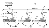
図1に実施形態として説明する、分散型電源用転送遮断システム1の概略的な構成を示している。同図に示すように、分散型電源用転送遮断システム1は、商用電力系統4を構成している配電設備2(柱上変圧器等)に付設されている第1通信装置10と、開閉器3を介して商用電力系統4に接続している一つ以上の分散型電源5の夫々に付設されている第2通信装置20とを含む。
Hereinafter, embodiments for carrying out the invention will be described with reference to the drawings.
FIG. 1 shows a schematic configuration of a distributed power transfer interruption system 1 described as an embodiment. As shown in the figure, a distributed power transfer interruption system 1 includes a
第1通信装置10は、中央制御所6に設けられている情報処理装置(不図示)と所定の通信手段7(例えば、インターネット、電力線通信(PLC:Power Line Communication))、専用線(電力系統制御用情報伝送システム(CDT:Cyclic Digital data Transmission equipment)、メタル線、光ファイバ等)、無線又は有線による公衆通信網)を介して通信する。また第1通信装置10は、第2通信装置20の夫々とマルチホップ方式による無線通信(以下、マルチホップ通信と称する。)により通信する。
The
開閉器3は、自身に付設されている第2通信装置20からの指示に応じて、分散型電源5の商用電力系統4への接続、もしくは分散型電源5の商用電力系統4からの切断(解列)を行う。第1通信装置10は、中央制御所6から制御信号を受信すると、受信した制御信号を第2通信装置20とマルチホップ通信を行って第2通信装置20に伝達する。第2通信装置20は、受信した制御信号に応じて開閉器3を制御し、上記接続又は切断を行う。
The
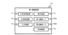
図2に第1通信装置10のハードウエア構成を示している。同図に示すように、第1通信装置10は、中央処理装置11、主記憶装置12、入力装置13、表示装置14、第1通信インターフェース15A(第1通信I/F)、第2通信インターフェース15B(第2通信I/F)、及び計時装置16を備えている。
FIG. 2 shows a hardware configuration of the
中央処理装置11は、CPU(Central Processing Unit)やMPU(Micro Processing Unit)などを用いて構成されており、第1通信装置10の統括的な制御を行う。主記憶装置12は、RAM(Random Access Memory)、ROM(Read Only Memory)、NVRAM(Non Volatile RAM)等を用いて構成されており、プログラムやデータを記憶する。入力装置13はテンキーやタッチパネル等のユーザインタフェースであり、ユーザから操作入力を受け付ける。表示装置14は、液晶パネルなどであり、視覚的な情報を出力する。
The central processing unit 11 is configured using a CPU (Central Processing Unit), an MPU (Micro Processing Unit), and the like, and performs overall control of the
第1通信インターフェース15Aは、第2通信装置20とマルチホップ通信を行う。また第2通信インターフェース15Bは、中央制御所6に設けられている情報処理装置と有線又は無線による通信を行う。計時装置16は、RTC(Real Time Clock)等を用いて構成されており、現在日時等の日時情報(タイムスタンプ)を出力する。
The
図3に第2通信装置20のハードウエア構成を示している。同図に示すように、第2通信装置20は、中央処理装置21、主記憶装置22、表示装置23、及び通信インターフェース24を備える。
FIG. 3 shows the hardware configuration of the
中央処理装置21は、CPUやMPUを用いて構成されており、第2通信装置20の統括的な制御を行う。主記憶装置22は、RAM、ROM、NVRAM等を用いて構成されており、プログラムやデータを記憶する。表示装置23は、液晶パネルなどであり、視覚的な情報を出力する。通信インターフェース24(通信I/F)は、第1通信装置10及び他の第2通信装置20とマルチホップ通信を行う。
The
図4に第1通信装置10が備える主な機能を示している。同図に示すように、第1通信装置10は、セッション確立部151、データ送受信部152、無通信時間計測部153、及び累積無通信時間計測部154を備えている。これらの機能は、第1通信装置10のハードウエアによって、もしくは、第1通信装置10の中央処理装置11が、主記憶装置12に格納されているプログラムを読み出して実行することにより実現される。
FIG. 4 shows main functions provided in the
セッション確立部151は、第2通信装置20との間でセッションを確立する。尚、セッションを確立するための前提となる、第1通信装置10と第2通信装置20との間の通信経路の確立は、両者間のマルチホップ通信を実現しているプロトコル(例えば、RIP(Routing Information Protocol)、OSPF(Open Shortest Path First)、BGP(Border Gateway Protocol)等)に従い、動的又は静的に行われる。
The
データ送受信部152は、中央制御所6の情報処理装置又は、第2通信装置20との間でデータの送受信を行う。データ送受信部152のセッション維持信号送信部1521は、自身と現在セッションを確立している第2通信装置20との間で、セッションを維持するための信号(以下、セッション維持信号と称する。)を送信する。
The data transmission /
無通信時間計測部153は、自身と現在セッションを確立している相手方の第2通信装置20との間で、セッションを確立してからデータの送受信が行われていない時間期間(以下、無通信時間と称する。)を計測する。
The no-communication
累積無通信時間計測部154は、セッション維持信号以外に第2通信装置20との間でデータの送受信が行われていない時間期間(以下、累積無通信時間と称する。)を計測する。
The accumulated no-communication
図5に第2通信装置20が備える主な機能を示している。同図に示すように、第2通信装置20は、データ送受信部251、及びデータ転送部252を備えている。これらの機能は、第2通信装置20のハードウエアによって、もしくは、第2通信装置20の中央処理装置21が、主記憶装置22に格納されているプログラムを読み出して実行することにより実現される。
FIG. 5 shows main functions of the
データ送受信部251は、第1通信装置10又は他の第2通信装置20との間でデータの送受信を行う。データ送受信部251のセッション維持信号受信部2511は、第1通信装置10又は他の第2通信装置20から送られてくるセッション維持信号を受信する。
The data transmission /
データ転送部252は、第1通信装置10又は他の第2通信装置20から送られてくるデータを、第1通信装置10又は更に別の第2通信装置20に転送する。データ転送部252のセッション維持信号転送部2521は、第1通信装置10又は他の第2通信装置20から送られてくるセッション維持信号を、第1通信装置10又は更に別の第2通信装置20に転送する。
The
=処理説明=
次に以上の構成からなる分散型電源用転送遮断システム1において行われる処理について説明する。
= Description of processing =
Next, processing performed in the distributed power transfer cutoff system 1 having the above configuration will be described.
<セッション確立処理>
第1通信装置10と各第2通信装置20との間では、所定のタイミングで随時セッションの確立が行われる。上記タイミングは、例えば、分散型電源用転送遮断システム1に新たな分散型電源5が導入された場合や、分散型電源5の障害復旧時、中央制御所6の情報処理装置から開閉器3の制御指示を受信した場合などである。
<Session establishment processing>
A session is established between the
図6は、上記セッションの確立に際し第1通信装置10と第2通信装置20との間で行われる処理(以下、セッション確立処理S600と称する。)を説明するフローチャートである。同図に示すように、まず第1通信装置10は、全ての第2通信装置20に向けてハローパケット700をブロードキャスト送信する(S611)。
FIG. 6 is a flowchart for explaining a process (hereinafter referred to as a session establishment process S600) performed between the
図7にハローパケット700の一例を示している。同図に示すように、ハローパケット700には、送信元情報701(例えば、第1通信装置10のネットワークアドレス。)及び宛先情報702(例えば、第2通信装置20のネットワークアドレス。)などの情報が含まれている。 FIG. 7 shows an example of the hello packet 700. As shown in the figure, the hello packet 700 includes information such as transmission source information 701 (for example, the network address of the first communication device 10) and destination information 702 (for example, the network address of the second communication device 20). It is included.
第2通信装置20は、ハローパケット700を受信すると(S612)、受信したハローパケット700に対する返信パケット(以下、ハローパケット応答800と称する。)を、第1通信装置10に送信する(S613)。
When receiving the hello packet 700 (S612), the
図8にハローパケット応答800の一例を示している。同図に示すように、ハローパケット応答800には、送信元情報801(例えば、第2通信装置20のネットワークアドレス。)及び宛先情報802(例えば、第1通信装置10のネットワークアドレス。)などの情報が含まれている。 FIG. 8 shows an example of the hello packet response 800. As shown in the figure, the hello packet response 800 includes transmission source information 801 (for example, the network address of the second communication device 20) and destination information 802 (for example, the network address of the first communication device 10). Contains information.
次に第1通信装置10は、第2通信装置20から送られてきたハローパケット応答800を受信すると、これを記憶する(S614)。次いで第1通信装置10は、ハローパケット応答800を送信してきた一つ以上の第2通信装置20にセッション確立要求900を送信する(S615)。
Next, when receiving the hello packet response 800 sent from the
図9にセッション確立要求900の一例を示している。同図に示すように、セッション確立要求900には、送信元情報901(例えば、第1通信装置10のネットワークアドレス。)及び宛先情報902(例えば、第2通信装置20のネットワークアドレス。)などの情報が含まれている。 FIG. 9 shows an example of the session establishment request 900. As shown in the figure, the session establishment request 900 includes transmission source information 901 (for example, the network address of the first communication device 10) and destination information 902 (for example, the network address of the second communication device 20). Contains information.
第2通信装置20は、第1通信装置10から送られてきたセッション確立要求900を受信すると(S616)、その応答であるセッション確立パケット1000を第1通信装置10に送信する(S617)。
When receiving the session establishment request 900 sent from the first communication apparatus 10 (S616), the
図10にセッション確立パケット1000の一例を示している。同図に示すように、セッション確立パケット1000には、送信元情報1001(例えば、第2通信装置20のネットワークアドレス。)、及び宛先情報1002(例えば、第1通信装置10のネットワークアドレス。)などの情報が含まれている。 FIG. 10 shows an example of the session establishment packet 1000. As shown in the figure, the session establishment packet 1000 includes transmission source information 1001 (for example, the network address of the second communication device 20), destination information 1002 (for example, the network address of the first communication device 10), and the like. Information is included.
第1通信装置10は、第2通信装置20から送られてきたセッション確立パケット1000を受信すると、これを記憶する(S618)。
When receiving the session establishment packet 1000 sent from the
次に第1通信装置10は、S618でセッション確立パケット1000を受信した一つ以上の第2通信装置20との間の各セッションについて、前述した無通信時間の計測を開始する(S619)。
Next, the
続いて第1通信装置10は、S614でハローパケット応答800を送信してきた全ての第2通信装置20から、セッション確立パケット1000を受信しているか否か判断する(S620)。ハローパケット応答800を受信した全ての第2通信装置20からセッション確立パケット1000を受信していれば(S620:YES)、処理は終了する。一方、未だセッション確立パケット1000を受信していない第2通信装置20が存在する場合には(S620:NO)、S615に戻る。
Subsequently, the
尚、セッション確立パケット1000を無期限に待機することのないように、セッション確立要求900のリトライ送信回数について上限を設けたり、セッション確立パケット1000の待機時間にタイムアウトを設定するようにしてもよい。セッション確立処理S600は以上のようにして行われる。 Note that an upper limit may be set for the number of retry transmissions of the session establishment request 900 or a timeout may be set for the waiting time of the session establishment packet 1000 so that the session establishment packet 1000 is not waited indefinitely. The session establishment process S600 is performed as described above.
<セッション維持処理>
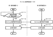
セッション確立処理S600が行われた後、第1通信装置10は、第2通信装置20との間で確立されている各セッションについて、前述した無通信時間が、セッションがタイムアウトする時間に近づいているか否かのリアルタイムな監視を開始し、近づいている場合はセッションがタイムアウトして切断しないように相手方の第2通信装置20にセッション維持信号を送信する。図11はこの処理(以下、セッション維持処理S1100と称する。)の詳細を説明したフローチャートである。以下、同図とともに説明する。
<Session maintenance processing>
After the session establishment process S600 is performed, for each session established with the
第1通信装置10は、第2通信装置20の間で確立されている各セッションについて、無通信時間tが予め設定された第1閾値時間T1(アイドルタイムリミット)を超えているか否かをリアルタイム監視する(S1111)。尚、第1閾値時間T1(<セッションがタイムアウトする時間)は、少なくとも第1通信装置10から第2通信装置20にセッション維持信号が到達するのに要する時間より長い時間に設定される。
The
無通信時間tが予め設定された第1閾値時間T1を超えていることを検知すると(S1111:YES)、第1通信装置10は、そのセッションの相手方の第2通信装置20にセッション維持信号1200を送信する(S1112)。
When it is detected that the no-communication time t exceeds a preset first threshold time T1 (S1111: YES), the
図12にセッション維持信号1200の一例を示している。同図に示すように、セッション維持信号1200には、送信元情報1201(例えば、第1通信装置10のネットワークアドレス。)、及び宛先情報1202(例えば、第2通信装置20のネットワークアドレス。)などの情報が含まれている。 FIG. 12 shows an example of the session maintenance signal 1200. As shown in the figure, the session maintenance signal 1200 includes transmission source information 1201 (for example, the network address of the first communication device 10), destination information 1202 (for example, the network address of the second communication device 20), and the like. Information is included.
尚、第1通信装置10と第2通信装置20がTCP/IP(Transmission Control Protocol/Internet Protocol)に従って通信している場合には、セッション維持信号1200として、通信経路の健全性の確認に用いるコマンド(例えばPINGコマンド)を用いることができる。このようにセッション維持信号1200として、通信経路の健全性の確認に用いるコマンドを送信するようにすれば、セッションの切断を防ぐとともに、通信経路の健全性を確認することができる。
When the
第2通信装置20は、第1通信装置10からセッション維持信号1200を受信すると(S1113)、その応答1300を第1通信装置10に送信する(S1114)。そして第1通信装置10は、第2通信装置20から送られてきた応答1300を受信する(S1115)。
When receiving the session maintenance signal 1200 from the first communication device 10 (S1113), the
図13に上記応答1300の一例を示している。同図に示すように、上記応答1300には、当該応答の送信元情報1301(例えば、第2通信装置20のネットワークアドレス。)、及び宛先情報1302(例えば、第1通信装置10のネットワークアドレス。)などの情報が含まれている。セッション維持処理S1100は以上のようにして行われる。
FIG. 13 shows an example of the response 1300. As shown in the figure, the response 1300 includes
以上に説明した通り、本実施形態の分散型電源用転送遮断システム1においては、第1通信装置10が、第2通信装置20との間でセッションを確立した後、第2通信装置20との間でデータの送受信が行われていない時間を計測し、セッションがタイムアウトする前に第2通信装置20に自動的にセッション維持信号1200を送信するので、セッションが確立された後、第1通信装置10と第2通信装置20との間でデータの送受信が行われていない場合でも、既に確立されているセッションが維持される。これによれば、セッションが再確立される頻度が減ってマルチホップ通信の伝送性能を向上させることができる。またこのように第1通信装置10と第2通信装置20との間で通信が行われたか否かに拘わらずセッションが長期間維持されるので、中央制御所6から第2通信装置20に迅速に制御指示を伝達して開閉器3を確実に制御することができる。
As described above, in the distributed power transfer cutoff system 1 according to the present embodiment, after the
以上に説明した実施の形態は、本発明の理解を容易にするためのものであり、本発明を限定するものではない。本発明は、その趣旨を逸脱することなく、変更、改良され得ると共に、本発明にはその等価物が含まれることは勿論である。 Embodiment described above is for making an understanding of this invention easy, and does not limit this invention. The present invention can be changed and improved without departing from the gist thereof, and the present invention includes the equivalents thereof.
例えば、セッション維持信号1200以外に第2通信装置20との間でデータの送受信が行われていない時間(前述した累積無通信時間)が所定の第2閾値時間T2(>セッションがタイムアウトする時間)を超えた後は、第1通信装置10から第2通信装置20へのセッション維持信号1200の送信を中止するようにしてもよい。そのようにすれば、長期に亘って不必要にセッションが維持されることによる帯域の減少やリソースの浪費を防ぐことができる。尚、累積無通信時間と第2閾値時間T2との比較に代えて、累積無通信時間内におけるセッション維持信号1200の送信回数を制限するようにしてもよい。また累積無通信時間が第2閾値時間T2を超えた際、セッションとともにコネクションを切断するようにしてもよいし、セッションのみを切断してコネクションについてはそのまま維持しておくようにしてもよい。このようにコネクションについてはそのまま維持しておくようにすることで、次回接続時にコネクションの確立を省略することができ、その分、通信効率を向上させることができる。
For example, a time during which data is not transmitted / received to / from the
また本実施形態では、図6とともに説明したように、第1通信装置10と一つ以上の複数の第2通信装置20との間のセッションの確立を一斉に行うようにしているが、第1通信装置10が第2通信装置20の夫々と個別にセッションを確立するようにしてもよい。
In the present embodiment, as described with reference to FIG. 6, session establishment between the
また本実施形態では、第1通信装置10と第2通信装置20との間のセッションを維持する仕組みについて説明したが、同様の仕組みを第2通信装置20と他の第2通信装置20との間のマルチホップ通信に適用すれば、第2通信装置20間のセッションが自動的に維持されるようにすることもできる。
In the present embodiment, the mechanism for maintaining the session between the
また第1通信装置10又は第2通信装置20に、第1閾値時間T1又は第2閾値時間T2をユーザに設定させるためのユーザインタフェースを設けてもよい。図14にユーザインタフェース(以下、設定画面1400と称する。)の一例を示す。同図に示すように、この設定画面1400には、第1閾値時間T1の設定欄141及び第2閾値時間T2の設定欄142などが設けられている。
Further, the
また以上の仕組みは、分散型電源用転送遮断システム1以外の様々な無線通信システムに応用することができる。例えば、車載端末のマルチホップ通信(車車間通信システム等)に適用することができる。 Further, the above mechanism can be applied to various wireless communication systems other than the distributed power transfer cutoff system 1. For example, the present invention can be applied to multi-hop communication (such as an inter-vehicle communication system) for in-vehicle terminals.
また以上の仕組みは、例えば、特開2004−184078号公報、特開2005−351877号公報、特開2005−351878号公報、特開2006−23261号公報に開示されている、高精度位置検知システムに応用することができる。即ち、これらの文献に開示されている高精度位置検知システムは、携帯端末の夫々から送信される電波を、基地局の複数のアンテナで受信し、各アンテナで受信した受信波の位相差から携帯端末の位置、方向を算出するものであるが、上記携帯端末間で行われるマルチホップ通信に本発明を提供すれば、携帯端末及び基地局の夫々の間で行われるマルチホップ通信の伝送性能を向上させることができる。 Moreover, the above mechanism is the high-precision position detection system currently disclosed by Unexamined-Japanese-Patent No. 2004-184078, Unexamined-Japanese-Patent No. 2005-351877, Unexamined-Japanese-Patent No. 2005-351878, Unexamined-Japanese-Patent No. 2006-23261, for example. It can be applied to. That is, the high-accuracy position detection systems disclosed in these documents receive radio waves transmitted from each of the mobile terminals by a plurality of antennas of the base station, and carry out the mobile from the phase difference of the received waves received by each antenna. If the present invention is provided for multi-hop communication performed between the mobile terminals, the transmission performance of multi-hop communication performed between the mobile terminal and the base station can be improved. Can be improved.
1 分散型電源用転送遮断システム
3 開閉器
4 商用電力系統
5 分散型電源
10 第1通信装置
20 第2通信装置
1200 セッション維持信号
DESCRIPTION OF SYMBOLS 1 Transfer interruption | blocking
Claims (7)
前記第1閾値時間は、前記第1通信装置から前記第2通信装置にセッション維持信号が到達するのに要する時間よりも長く、かつ、前記セッションがタイムアウトする時間よりも短い時間に設定される
ことを特徴とするマルチホップ通信方法。 After the first communication device establishes a session with the second communication device, it measures a non-communication time , which is a time during which data transmission / reception is not performed with the second communication device, and the non-communication Upon detecting that the time exceeds a preset first threshold time , a session maintenance signal that is a signal for automatically maintaining the session is transmitted to the second communication device ,
The first threshold time is set to be longer than the time required for the session maintenance signal to reach the second communication device from the first communication device and shorter than the time for the session to time out. A multi-hop communication method.
前記セッション維持信号は、前記第1通信装置と前記第2通信装置との間の通信経路の健全性の確認に用いるコマンドを含むことを特徴とするマルチホップ通信方法。 The multi-hop communication method according to claim 1,
The session maintenance signal includes a command used for confirming soundness of a communication path between the first communication device and the second communication device.
前記第1通信装置と前記第2通信装置はTCP/IP(Transmission Control Protocol/Internet Protocol)に従って通信を行い、前記コマンドはPINGコマンドであることを特徴とするマルチホップ通信方法。 The multi-hop communication method according to claim 2,
The first communication device and the second communication device communicate according to TCP / IP (Transmission Control Protocol / Internet Protocol), and the command is a PING command.
前記第1通信装置が複数の前記第2通信装置に対して一のハローパケットをブロードキャスト送信し、
前記複数の第2通信装置の夫々が前記ハローパケットを受信して前記第1通信装置に返信パケットを送信し、
前記第1通信装置が前記返信パケットを受信して記憶し、
前記第1通信装置が前記第2通信装置の夫々にセッション確立要求を送信し、
前記複数の第2通信装置の夫々が前記セッション確立要求を受信してセッション確立パケットを前記第1通信装置に送信し、
前記第1通信装置が前記複数の第2通信装置の夫々から送られてくる前記セッション確立パケットを受信する
ことにより、前記複数の第2通信装置について前記セッションを確立する
ことを特徴とするマルチホップ通信方法。 The multi-hop communication method according to claim 1,
The first communication device broadcasts one hello packet to the plurality of second communication devices ,
Wherein each of the plurality of the second communication device receives the hello packet transmitted the reply packet to the first communication device,
The first communication device receives and stores the reply packet;
The first communication device transmits a session establishment request to each of the second communication devices;
Wherein each of the plurality of the second communication device receives the session establishment request sends a session establishment packet to the first communication device,
The first communication device establishes the session for the plurality of second communication devices by receiving the session establishment packet sent from each of the plurality of second communication devices. Communication method.
前記第1通信装置は、前記セッション維持信号以外に前記第2通信装置との間でデータの送受信が行われていない時間である累積無通信時間が第2閾値時間(>セッションがタイムアウトする時間)を超えた後は、前記セッション維持信号の送信を中止することを特徴とするマルチホップ通信方法。 The multi-hop communication method according to claim 1,
The first communication device has a second threshold time (> time for session timeout) that is a time during which data is not transmitted / received to / from the second communication device other than the session maintenance signal. The multi-hop communication method is characterized in that transmission of the session maintenance signal is stopped after exceeding.
電力系統と分散型電源との間の接続/切断を制御する開閉器に前記第2通信装置を設け、前記第2通信装置に、前記第1通信装置から受信したデータに応じて前記開閉器を制御させる
ことを特徴とするマルチホップ通信方法。 The multi-hop communication method according to claim 1,
A switch for controlling connection / disconnection between a power system and a distributed power source is provided with the second communication device, and the switch is provided in the second communication device according to data received from the first communication device. A multi-hop communication method characterized by controlling.
前記第1閾値時間は、前記通信装置から前記他の通信装置にセッション維持信号が到達するのに要する時間よりも長く、かつ、前記セッションがタイムアウトする時間よりも短い時間に設定される
ことを特徴とする通信装置。 A communication device that performs multi-hop communication, and after establishing a session with another communication device, measures a non-communication time , which is a time during which no data is transmitted to or received from the other communication device. When it is detected that the no-communication time exceeds a preset first threshold time , a session maintenance signal that is a signal for automatically maintaining the session is transmitted to the other communication device. ,
The first threshold time is set to be longer than the time required for a session maintenance signal to reach the other communication device from the communication device and shorter than the time for the session to time out. A communication device.
Priority Applications (1)
| Application Number | Priority Date | Filing Date | Title |
|---|---|---|---|
| JP2011068251A JP5241874B2 (en) | 2011-03-25 | 2011-03-25 | Multi-hop communication method and communication apparatus |
Applications Claiming Priority (1)
| Application Number | Priority Date | Filing Date | Title |
|---|---|---|---|
| JP2011068251A JP5241874B2 (en) | 2011-03-25 | 2011-03-25 | Multi-hop communication method and communication apparatus |
Publications (2)
| Publication Number | Publication Date |
|---|---|
| JP2012205106A JP2012205106A (en) | 2012-10-22 |
| JP5241874B2 true JP5241874B2 (en) | 2013-07-17 |
Family
ID=47185598
Family Applications (1)
| Application Number | Title | Priority Date | Filing Date |
|---|---|---|---|
| JP2011068251A Active JP5241874B2 (en) | 2011-03-25 | 2011-03-25 | Multi-hop communication method and communication apparatus |
Country Status (1)
| Country | Link |
|---|---|
| JP (1) | JP5241874B2 (en) |
Family Cites Families (6)
| Publication number | Priority date | Publication date | Assignee | Title |
|---|---|---|---|---|
| JP2004186972A (en) * | 2002-12-03 | 2004-07-02 | Matsushita Electric Ind Co Ltd | Session connection method and network system |
| US7483409B2 (en) * | 2005-12-30 | 2009-01-27 | Motorola, Inc. | Wireless router assisted security handoff (WRASH) in a multi-hop wireless network |
| JP2008022222A (en) * | 2006-07-12 | 2008-01-31 | Chugoku Electric Power Co Inc:The | Communication network organizing method and inspection tour support method |
| JP4980151B2 (en) * | 2007-06-18 | 2012-07-18 | 株式会社日立製作所 | MOBILE COMMUNICATION SYSTEM, PDIF, AND MONITORING MONITORING METHOD FOR MOBILE TERMINAL |
| JP4231893B1 (en) * | 2008-03-27 | 2009-03-04 | 中国電力株式会社 | Transfer block system for distributed power supply |
| JP4881915B2 (en) * | 2008-06-11 | 2012-02-22 | キヤノンソフトウェア株式会社 | Printing system, print management server, control method therefor, and program |
-
2011
- 2011-03-25 JP JP2011068251A patent/JP5241874B2/en active Active
Also Published As
| Publication number | Publication date |
|---|---|
| JP2012205106A (en) | 2012-10-22 |
Similar Documents
| Publication | Publication Date | Title |
|---|---|---|
| JP4265620B2 (en) | ACCESS CONTROL DEVICE, WIRELESS DEVICE, NETWORK, ACCESS CONTROL METHOD, AND ACCESS CONTROL PROGRAM | |
| ES2758988T3 (en) | Method, device and system to control air interface resources | |
| CN106470117B (en) | Transmission switching method, equipment and the system of LTE broadband cluster system | |
| US20190364437A1 (en) | Communication processing system, communication processing method, communication processing apparatus, and control method and control program thereof | |
| JPWO2013014847A1 (en) | Wireless communication system, base station, control node, mobile station, and method and program related thereto | |
| EP3291589B1 (en) | Method and device for providing relay service | |
| CN110446274B (en) | Tunnel establishment method and device | |
| CN103491005A (en) | Method for controlling transmission of message, access point device and relevant system | |
| WO2013177972A1 (en) | Data transmitting and forwarding method, device, and system | |
| EP3035609A1 (en) | Data transmission method and device | |
| AU2020208539B2 (en) | Resource periodicity configuration method and device, link processing and establishing method and device | |
| JP2017531970A (en) | Interface establishment method and apparatus | |
| CN114039645A (en) | Satellite base station switching method and device, electronic equipment and storage medium | |
| KR20140039999A (en) | Method and apparatus of temporary local transmission for disaster information delivery | |
| EP3367747B1 (en) | Access node, mobility management network element, and paging message processing method | |
| JP6281192B2 (en) | Base station apparatus, handover control method, and radio communication system | |
| JP2010233072A (en) | Radio network system | |
| JP5241874B2 (en) | Multi-hop communication method and communication apparatus | |
| JP6255730B2 (en) | Wireless communication system, location registration method, relay device, and wireless terminal device | |
| JP2011130182A (en) | Wireless base station system, and relay device | |
| JP2017509285A (en) | Configuration method, network device, and user equipment | |
| CN117121556A (en) | Handover techniques for time-sensitive networking | |
| JP2007096968A (en) | Mobile communication system, base station apparatus, and handover method | |
| JP6315208B2 (en) | COMMUNICATION SYSTEM, COMMUNICATION DEVICE, AND LINE SELECTION CONTROL METHOD | |
| EP3276898A1 (en) | Resource switching method, apparatus and system |
Legal Events
| Date | Code | Title | Description |
|---|---|---|---|
| A977 | Report on retrieval |
Free format text: JAPANESE INTERMEDIATE CODE: A971007 Effective date: 20130124 |
|
| A131 | Notification of reasons for refusal |
Free format text: JAPANESE INTERMEDIATE CODE: A131 Effective date: 20130129 |
|
| A521 | Written amendment |
Free format text: JAPANESE INTERMEDIATE CODE: A523 Effective date: 20130221 |
|
| TRDD | Decision of grant or rejection written | ||
| A01 | Written decision to grant a patent or to grant a registration (utility model) |
Free format text: JAPANESE INTERMEDIATE CODE: A01 Effective date: 20130326 |
|
| A61 | First payment of annual fees (during grant procedure) |
Free format text: JAPANESE INTERMEDIATE CODE: A61 Effective date: 20130402 |
|
| FPAY | Renewal fee payment (event date is renewal date of database) |
Free format text: PAYMENT UNTIL: 20160412 Year of fee payment: 3 |
|
| R150 | Certificate of patent or registration of utility model |
Free format text: JAPANESE INTERMEDIATE CODE: R150 Ref document number: 5241874 Country of ref document: JP Free format text: JAPANESE INTERMEDIATE CODE: R150 |
|
| R250 | Receipt of annual fees |
Free format text: JAPANESE INTERMEDIATE CODE: R250 |
|
| R250 | Receipt of annual fees |
Free format text: JAPANESE INTERMEDIATE CODE: R250 |
|
| R250 | Receipt of annual fees |
Free format text: JAPANESE INTERMEDIATE CODE: R250 |
|
| R250 | Receipt of annual fees |
Free format text: JAPANESE INTERMEDIATE CODE: R250 |