JP5240310B2 - Timing adjustment method, mobile station, base station, and mobile communication system - Google Patents
Timing adjustment method, mobile station, base station, and mobile communication system Download PDFInfo
- Publication number
- JP5240310B2 JP5240310B2 JP2011052981A JP2011052981A JP5240310B2 JP 5240310 B2 JP5240310 B2 JP 5240310B2 JP 2011052981 A JP2011052981 A JP 2011052981A JP 2011052981 A JP2011052981 A JP 2011052981A JP 5240310 B2 JP5240310 B2 JP 5240310B2
- Authority
- JP
- Japan
- Prior art keywords
- transmission
- timing adjustment
- mobile station
- base station
- adjustment information
- Prior art date
- Legal status (The legal status is an assumption and is not a legal conclusion. Google has not performed a legal analysis and makes no representation as to the accuracy of the status listed.)
- Active
Links
Images


Description
本件は、タイミング調整方法、移動局、基地局および移動通信システムに関する。本件は、無線(移動)通信システムの上り(アップリンク:UL)の通信制御に用いられる場合がある。 The present case relates to a timing adjustment method, a mobile station, a base station, and a mobile communication system. This case may be used for uplink (uplink: UL) communication control of a wireless (mobile) communication system.
携帯電話などの無線端末(移動局)を含む無線(移動)通信システムとして、現在、code division multiple access(CDMA)方式を用いた第3世代移動通信サービスが提供されている。一方、より高速な通信を可能とする次世代移動通信方式も検討されている。3rd Generation Partnership Project(3GPP)においては、Long Term Evolution(LTE)として次世代移動通信方式の検討が行なわれている。 As a wireless (mobile) communication system including a wireless terminal (mobile station) such as a mobile phone, a third generation mobile communication service using a code division multiple access (CDMA) system is currently provided. On the other hand, next-generation mobile communication systems that enable higher-speed communication are also being studied. In the 3rd Generation Partnership Project (3GPP), the next generation mobile communication system is being studied as Long Term Evolution (LTE).
移動通信システムにおいては、無線基地局(evolved Node B:eNB)と移動局(User Equipment:UE)とが通信を開始するにあたって、UEがeNBに対して送信を開始する際に用いられるチャネルが用意される。3GPPにおいては、このチャネルをランダムアクセスチャネル(RACH)と呼び、RACHによる通信開始手順をランダムアクセス(RA)と呼ぶ。 In a mobile communication system, when a radio base station (evolved Node B: eNB) and a mobile station (User Equipment: UE) start communication, a channel used when the UE starts transmission to the eNB is prepared. Is done. In 3GPP, this channel is called a random access channel (RACH), and the communication start procedure by RACH is called random access (RA).
LTEにおけるランダムアクセスはSlotted Aloha方式で設計されており、RACHを送信するための時間・周波数リソースが確保されている。RACHには、eNBがUEからの送信を識別するための情報が含まれる。即ち、複数のUEで共通にRACHを使用可能とすべく、シグニチャ(あるいはプリアンブル)と呼ばれる識別子が含まれる。
UEは、複数のシグニチャの候補のうち、いずれかのシグニチャを用いて送信を行なうことで、異なるUEが、たとえ同じ時間・周波数リソースを使ってRACHを介してシグニチャの送信を行なっても、各UEが異なるシグニチャを用いていれば、eNBは、受信したシグニチャに基づいて、UEを識別することができる。
The random access in LTE is designed by the Slotted Aloha method, and time and frequency resources for transmitting the RACH are secured. The RACH includes information for the eNB to identify transmission from the UE. That is, an identifier called a signature (or preamble) is included so that the RACH can be commonly used by a plurality of UEs.
The UE performs transmission using any one of a plurality of signature candidates, so that even if different UEs transmit the signature via the RACH using the same time and frequency resources, If the UE uses a different signature, the eNB can identify the UE based on the received signature.
なお、RACHは、通信開始時に使用され、以降は個別チャネル(または共有チャネル)が使用される。
UEがRAを実行する契機としては、例えば、初回送信(発信)時、eNBから着信があった時(ダウンリンク(DL)データの発生時)、ハンドオーバ時、接続解除後の復帰時(中断した通信の再開時)などがある。なお、eNBからUEへの方向の無線リンクがダウンリンク(DL)であり、その逆の方向の無線リンクがアップリンク(UL)である。
RACH is used at the start of communication, and thereafter, an individual channel (or shared channel) is used.
For example, when the UE performs RA, for example, at the time of initial transmission (outgoing), when there is an incoming call from the eNB (when downlink (DL) data is generated), at the time of handover, at the time of return after disconnection (interrupted) When communication is resumed). Note that the radio link in the direction from the eNB to the UE is the downlink (DL), and the radio link in the opposite direction is the uplink (UL).
ここで、初回送信時や接続解除後の復帰時など、eNBで存在が管理できていないUEには、排他的に使用可能な個別のシグニチャが割り当てられていない場合がある。そのようなUEは、予め用意されている複数(例えば64種類)のシグニチャの中から一つを選んでRAを行なう。したがって、低い確率ではあるが、複数のUEが同時に同じシグニチャを用いてRAを行なうことが起こり得る。このようなRA方法をcontention based random access procedure(コンテンションベースRA手順)という。 Here, there may be a case where an individual signature that can be used exclusively is not assigned to a UE whose presence cannot be managed by the eNB, such as at the time of initial transmission or when returning after connection release. Such a UE performs RA by selecting one from a plurality of (for example, 64 types) signatures prepared in advance. Therefore, although with a low probability, multiple UEs may simultaneously perform RA using the same signature. Such an RA method is referred to as a contention based random access procedure.
この場合に、eNBは、競合するシグニチャ(UE)の解決(選択)を行ない、選択したUEへ応答を行なう。UEは、eNBから受信した前記応答を基に、自身がeNBに選択されたかどうかを判断する。eNBに選択されたUEは、eNBとの通信(RA手順)を継続して、eNBとの間の無線チャネル設定などを行なう。eNBに選択されなかったUEは、一定時間経過後などに、RAを再実行する。 In this case, the eNB resolves (selects) the conflicting signature (UE) and responds to the selected UE. Based on the response received from the eNB, the UE determines whether it has been selected by the eNB. The UE selected as the eNB continues communication with the eNB (RA procedure), and performs radio channel setting and the like with the eNB. The UE that has not been selected by the eNB re-executes RA after a certain time has elapsed.
なお、UEが接続先のeNBを切り替えるハンドオーバを実行する場合にこのようなシグニチャの衝突が発生すると、接続の瞬断や、場合によっては通信が切断される。そのため、LTEでは、ハンドオーバを行なうUEには、予め個別のシグニチャを割り当てることが提案されている。このようなRA方法を、 non-contention based random access procedure(非コンテンションベースRA手順)と呼ぶ。
従来技術では、RAの過程(実行途中)で、送信タイミングの調整情報の有効期限が切れたり等、送信タイミングの調整等において不都合が生ずることがある。
そこで、基地局から端末(移動局)への送信タイミングの調整等において生じ得る不都合を解決することを目的とする。
他の目的の一つは、移動局が基地局に接続して通信を開始できるようになるまでの遅延時間を低減することにある。
In the prior art, in the RA process (during execution), inconvenience may occur in the adjustment of the transmission timing, such as the expiration date of the adjustment information of the transmission timing being expired.
Accordingly, it is an object to solve problems that may occur in adjustment of transmission timing from a base station to a terminal (mobile station).
Another object is to reduce the delay time until the mobile station can connect to the base station and start communication.
なお、前記目的に限らず、後述する実施形態に示す各構成により導かれる作用効果であって、従来の技術によっては得られない作用効果を奏することも他の目的の一つとして位置付けることができる。 It should be noted that the present invention is not limited to the above-described object, and can be positioned as one of other objects that is an effect obtained by each configuration shown in the embodiments to be described later and that cannot be obtained by conventional techniques. .
例えば、以下の手段を用いる。
(1)移動局と基地局とを備えた移動通信システムにおけるタイミング調整方法において、前記移動局で、送信タイミング調整情報に基づいて、送信処理を行ない、前記移動局と基地局との間で、送信処理に用いるPUCCH(Physical Uplink Control Channel)リソースに関する複数のパラメータを割り当て、前記移動局で、第1の送信タイミング調整情報を有し前記基地局に対する接続処理を行なっている場合に、第2の送信タイミング調整情報の受信を含む該接続処理の過程で、該第1の送信タイミング調整情報の有効期限が、該移動局の識別情報を含む信号の送信を行なう前に到来すると、前記送信を行なわないと共に、割り当てられたPUCCHリソースに関する複数のパラメータの一部を解放する、タイミング調整方法を用いることができる。
For example, the following means are used.
(1) In a timing adjustment method in a mobile communication system including a mobile station and a base station, the mobile station performs transmission processing based on transmission timing adjustment information, and between the mobile station and the base station, When a plurality of parameters related to PUCCH (Physical Uplink Control Channel) resources used for transmission processing are assigned and the mobile station has first transmission timing adjustment information and performs connection processing to the base station, In the course of the connection process including reception of transmission timing adjustment information, if the expiration date of the first transmission timing adjustment information arrives before transmitting a signal including identification information of the mobile station, the transmission is performed. with no releasing part of a plurality of parameters related to the allocated PUCCH resources, it is possible to use a timing adjusting method The
(2)移動局と基地局とを備えた移動通信システムにおけるタイミング調整方法において、前記移動局で、送信タイミング調整情報に基づいて、送信処理を行ない、前記移動局と基地局との間で、送信処理に用いるPUCCHリソースに関する複数のパラメータを割り当て、前記移動局で、第1の送信タイミング調整情報を有し前記基地局に対する接続処理を行なっている場合に、第2の送信タイミング調整情報の受信を含む該接続処理の過程で、該第1の送信タイミング調整情報の有効期限が、該移動局の識別情報を含む信号の送信を行なう前に到来すると、前記送信を行なわないと共に、SRI(Scheduling Request Indicator)に関わるパラメータ、CQI(Channel Quality Information)に関わるパラメータ、及びSRS(Sounding Reference Signal)に関わるパラメータをセットで解放する、タイミング調整方法を用いることができる。 (2) In a timing adjustment method in a mobile communication system including a mobile station and a base station, the mobile station performs transmission processing based on transmission timing adjustment information, and between the mobile station and the base station, When a plurality of parameters related to PUCCH resources used for transmission processing are allocated and the mobile station has first transmission timing adjustment information and performs connection processing to the base station , reception of second transmission timing adjustment information in the course of the connection process including, along with the expiration date of the transmission timing adjustment information of the first is, when arriving before performing transmit a signal including the identification information of the mobile station does not perform the transmission, SRI ( Parameters related to Scheduling Request Indicator (CEDI), parameters related to CQI (Channel Quality Information), and SRS (Sounding Reference Signal) Releasing the parameter sets can be used timing adjustment method.
(3)移動局と基地局とを備えた移動通信システムにおいて、前記移動局は、送信タイミング調整情報に基づいて、送信処理を行なう送信処理部と、第1の送信タイミング調整情報を有し前記基地局に対する接続処理を行なっている場合に、第2の送信タイミング調整情報の受信を含む該接続処理の過程で、該第1の送信タイミング調整情報の有効期限が、該移動局の識別情報を含む信号の送信を行なう前に到来すると、前記送信を行なわないと共に、前記移動局と基地局との間で割り当てられる、送信処理に用いるPUCCHリソースに関する複数のパラメータについて、割り当てられたPUCCHリソースに関する複数のパラメータの一部を解放する制御部と、を備える移動通信システムを用いることができる。 (3) In a mobile communication system including a mobile station and a base station, the mobile station includes a transmission processing unit that performs transmission processing based on transmission timing adjustment information, and first transmission timing adjustment information. When connection processing to the base station is performed, in the connection processing process including reception of the second transmission timing adjustment information, the expiration date of the first transmission timing adjustment information indicates the identification information of the mobile station. If it arrives before the transmission of the signal including it, the transmission is not performed, and a plurality of parameters related to the PUCCH resource used for transmission processing, which are allocated between the mobile station and the base station, a control unit for releasing the part of the parameters, it is possible to use a mobile communication system comprising a.
(4)移動局と基地局とを備えた移動通信システムにおいて、前記移動局は、送信タイミング調整情報に基づいて、送信処理を行なう送信処理部と、第1の送信タイミング調整情報を有し前記基地局に対する接続処理を行なっている場合に、第2の送信タイミング調整情報の受信を含む該接続処理の過程で、該第1の送信タイミング調整情報の有効期限が、該移動局の識別情報を含む信号の送信を行なう前に到来すると、前記送信を行なわないと共に、前記移動局と基地局との間で割り当てられる、送信処理に用いるPUCCHリソースに関する複数のパラメータについて、SRIに関わるパラメータ、CQIに関わるパラメータ、及びSRSに関わるパラメータをセットで解放する制御部と、を備える移動通信システムを用いることができる。 (4) in a mobile communication system comprising a mobile station and a base station, the mobile station, based on transmission timing adjustment information, the includes a transmission processing unit that performs transmission processing, the first transmission timing adjustment information When connection processing to the base station is performed, in the connection processing process including reception of the second transmission timing adjustment information, the expiration date of the first transmission timing adjustment information indicates the identification information of the mobile station. When arriving before performing transmit signals including, with not performing the transmission, it is allocated between the mobile station and a base station for a plurality of parameters related to PUCCH resources used for the transmission process, the parameters relating to SRI, CQI And a control unit that releases a parameter related to SRS and a parameter related to SRS as a set can be used. .
(5)移動局と基地局とを備えた移動通信システムにおける前記移動局であって、送信タイミング調整情報に基づいて、送信処理を行なう送信処理部と、第1の送信タイミング調整情報を有し前記基地局に対する接続処理を行なっている場合に、第2の送信タイミング調整情報の受信を含む該接続処理の過程で、該第1の送信タイミング調整情報の有効期限が、該移動局の識別情報を含む信号の送信を行なう前に到来すると、前記送信を行なわないと共に、前記移動局と基地局との間で割り当てられる、送信処理に用いるPUCCHリソースに関する複数のパラメータについて、割り当てられたPUCCHリソースに関する複数のパラメータの一部を解放する制御部と、を備える移動局を用いることができる。 (5) A mobile station in a mobile communication system comprising a mobile station and a base station, comprising: a transmission processing unit that performs transmission processing based on transmission timing adjustment information; and first transmission timing adjustment information When connection processing to the base station is being performed, in the course of the connection processing including reception of second transmission timing adjustment information, the expiration date of the first transmission timing adjustment information is the identification information of the mobile station. When a signal containing a signal containing the PUCCH resource is transmitted, the transmission is not performed, and a plurality of parameters related to the PUCCH resource used for transmission processing allocated between the mobile station and the base station are related to the allocated PUCCH resource. a control unit for releasing part of a plurality of parameters, it is possible to use a mobile station comprising a.
(6)移動局と基地局とを備えた移動通信システムにおける前記移動局であって、送信タイミング調整情報に基づいて、送信処理を行なう送信処理部と、第1の送信タイミング調整情報を有し前記基地局に対する接続処理を行なっている場合に、第2の送信タイミング調整情報の受信を含む該接続処理の過程で、該第1の送信タイミング調整情報の有効期限が、該移動局の識別情報を含む信号の送信を行なう前に到来すると、前記送信を行なわないと共に、前記移動局と基地局との間で割り当てられる、送信処理に用いるPUCCHリソースに関する複数のパラメータについて、SRIに関わるパラメータ、CQIに関わるパラメータ、及びSRSに関わるパラメータをセットで解放する制御部と、を備える移動局を用いることができる。 (6) The above mobile station in a mobile communication system comprising a mobile station and a base station, comprising, based on transmission timing adjustment information, a transmission processing unit that performs transmission processing, the first transmission timing adjustment information When connection processing to the base station is being performed, in the course of the connection processing including reception of second transmission timing adjustment information, the expiration date of the first transmission timing adjustment information is the identification information of the mobile station. When arriving before performing sending of a signal including, with not performed the transmission, is allocated between the mobile station and a base station for a plurality of parameters related to PUCCH resources used for the transmission process, the parameters relating to SRI, A mobile station including a parameter related to CQI and a control unit that releases parameters related to SRS as a set can be used.
(7)移動局と基地局とを備えた移動通信システムにおける前記基地局であって、前記移動局と基地局との間で、送信処理に用いるPUCCHリソースに関する複数のパラメータを割り当てるUL(Uplink)リソース管理部、を備えると共に、送信タイミング調整情報に基づいて、送信処理を行なう送信処理部と、第1の送信タイミング調整情報を有し前記基地局に対する接続処理を行なっている場合に、第2の送信タイミング調整情報の受信を含む該接続処理の過程で、該第1の送信タイミング調整情報の有効期限が、該移動局の識別情報を含む信号の送信を行なう前に到来すると、前記送信を行なわないと共に、割り当てられたPUCCHリソースに関する複数のパラメータの一部を解放する制御部と、を有する前記移動局から送信された信号を受信する受信処理部、を備える基地局を用いることができる。 (7) UL (Uplink) in the mobile communication system including a mobile station and a base station, in which a plurality of parameters relating to PUCCH resources used for transmission processing are allocated between the mobile station and the base station A resource management unit, a transmission processing unit that performs transmission processing based on the transmission timing adjustment information, and a second processing unit that includes first transmission timing adjustment information and performs connection processing for the base station. In the course of the connection process including reception of transmission timing adjustment information of the mobile station, if the expiration date of the first transmission timing adjustment information arrives before transmitting a signal including identification information of the mobile station, the transmission is performed. with not performed, and a control unit for releasing part of a plurality of parameters related to the allocated PUCCH resources transmitted from the mobile station having Reception processing unit for receiving the items, it is possible to use a base station comprising a.
(8)移動局と基地局とを備えた移動通信システムにおける前記基地局であって、前記移動局と基地局との間で、送信処理に用いるPUCCHリソースに関する複数のパラメータを割り当てるULリソース管理部、を備えると共に、送信タイミング調整情報に基づいて、送信処理を行なう送信処理部と、第1の送信タイミング調整情報を有し前記基地局に対する接続処理を行なっている場合に、第2の送信タイミング調整情報の受信を含む該接続処理の過程で、該第1の送信タイミング調整情報の有効期限が、該移動局の識別情報を含む信号の送信を行なう前に到来すると、前記送信を行なわないと共に、SRIに関わるパラメータ、CQIに関わるパラメータ、及びSRSに関わるパラメータをセットで解放する制御部と、を有する前記移動局から送信された信号を受信する受信処理部、を備える基地局を用いることができる。 (8) An UL resource management unit that is a base station in a mobile communication system including a mobile station and a base station, and allocates a plurality of parameters related to PUCCH resources used for transmission processing between the mobile station and the base station. provided with a, based on transmission timing adjustment information, and a transmission processing unit that performs transmission processing, when doing the connection processing to the base station having a first transmission timing adjustment information, the second transmission timing in the course of the connection process including the reception of the adjustment information, the expiration date of the transmission timing adjustment information of the first is, when arriving before performing transmit a signal including the identification information of the mobile station does not perform the transmission And a controller that releases a parameter related to SRI, a parameter related to CQI, and a parameter related to SRS as a set. Reception processing unit for receiving a signal transmitted from the station, it is possible to use a base station comprising a.
基地局から移動局への送信タイミングの調整等において生じ得る不都合を解決することが可能となる。
移動局が基地局に接続して通信を開始できるようになるまでの遅延時間を低減することも可能である。
It is possible to solve inconveniences that may occur in adjustment of transmission timing from the base station to the mobile station.
It is also possible to reduce the delay time until the mobile station can connect to the base station and start communication.
以下、図面を参照して実施の形態を説明する。ただし、以下に説明する実施形態は、あくまでも例示であり、以下に明示しない種々の変形や技術の適用を排除する意図はない。即ち、本実施形態は、その趣旨を逸脱しない範囲で種々変形(各実施例を組み合わせる等)して実施することができる。
〔1〕第1実施形態
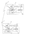
図1は、第1実施形態に係る無線(移動)通信システムの一例を示すブロック図である。この図1に例示するシステムは、無線基地局の一例としてのeNB10と、eNB10の無線エリアにおいて無線リンクを介してeNB10と通信する、無線端末(移動局)の一例としてのUE20と、をそなえる。
Hereinafter, embodiments will be described with reference to the drawings. However, the embodiment described below is merely an example, and there is no intention to exclude various modifications and technical applications that are not explicitly described below. That is, the present embodiment can be implemented with various modifications (combining the examples) without departing from the spirit of the present embodiment.
[1] First Embodiment FIG. 1 is a block diagram illustrating an example of a wireless (mobile) communication system according to a first embodiment. The system illustrated in FIG. 1 includes an
この図1では、1台のeNB10と、1台のUE20とに着目しているが、eNB10及びUE20は、それぞれ、前記無線通信システムにおいて複数存在することができる。前記無線リンクには、DL及びULの無線チャネルが含まれる。前記DL及びULの無線チャネルのそれぞれには、複数のUEにより共有される共有チャネルと、個々のUEが排他的に使用可能な個別チャネルと、が含まれ得る。
In FIG. 1, attention is focused on one eNB 10 and one
また、図1中に例示するeNB10及びUE20の構成は、以降の第2及び第3実施形態においても、特に断らない限り、共通で構わない。さらに、本例での無線基地局10は、無線ネットワーク制御装置(RNC)の機能の一部又は全部を具備するLTEでのeNBであることを想定しているが、LTEよりも前の世代での(RNCの機能が組み込まれない)基地局であっても構わない。加えて、RA手順が規定された他のシステムの基地局でもよい。
Also, the configurations of the
(1.1)eNBの説明
eNB10は、例示的に、送受信アンテナ11と、送受信部12と、バッファ13と、UL同期判定部14と、タイマ管理部15と、ULリソース管理部16と、をそなえる。
送受信アンテナ11(以下、単に「アンテナ11」と表記することもある)は、eNB10が提供する無線エリア(セル又はセクタ)に存在するUE20にて受信され得るDLの無線信号を送信する一方、UE20が送信したULの無線信号を受信する。
(1.1) Description of
The transmission / reception antenna 11 (hereinafter also simply referred to as “
送受信部12は、UE20宛の送信データ(ユーザデータ、制御データなどが含まれる)に対して所定の送信処理を施して無線チャネルの信号を生成し、送受信アンテナ11へ出力する。前記送信処理には、例示的に、DLの送信データの符号化、符号化データの変調、変調信号の所定チャネルのフレームへのマッピング、フレーム信号の無線周波数への周波数変換(アップコンバート)、無線フレームの電力増幅、などが含まれ得る。前記無線フレームには、例えば、 Orthogonal Frequency Division Multiplexing(OFDM)やOrthogonal Frequency Division Multiple Access(OFDMA)をベースとする無線フレームを適用できる。
The transmission /
また、送受信部12は、アンテナ11で受信されたULの無線信号(無線フレーム)について所定の受信処理を施して、UE20が送信したULのデータ(ユーザデータ、制御データなどが含まれる)を取得する。前記受信処理には、例示的に、受信信号の低雑音増幅、ベースバンド周波数への周波数変換(ダウンコンバート)、利得調整、復調、復号などが含まれ得る。なお、送受信部12は、機能的に、送信部と受信部とに別けて備えられてもよい。
Further, the transmission /
バッファ部13は、ULの受信データ及び/又はDLの送信データを一時的に保持する。
タイマ管理部15は、ULの同期を確保(維持)するためにUE20へ周期的に送信(通知)する、送信タイミング調整情報の一例としてのTA(Time Alignment)値を生成する。このTA値の生成、通知は、呼設定及びUE20がULのデータ送信に用いる無線リソース(ULリソース)の割当を行なったUE20について行なわれる。
The
The
TA値は、UE20によるULデータの送信タイミングと、eNB10によるULデータの受信タイミングとを揃える(同期させる)ために用いられる制御情報の一つである。つまり、TA値は、送受信部12において適切なタイミングで受信処理できるように、UE20のULの送信タイミングを調整するのに用いられる。したがって、UE20は、eNB10から受信したTA値に応じてULの送信タイミングを調整することで、ULの同期を確保することができる。
The TA value is one piece of control information used to align (synchronize) the UL data transmission timing by the
UE20は、同じ位置に止まるとは限らないから、TA値は、eNB10とUE20との間の距離(UE20の位置)に応じた可変値となる。故に、UE20がULの同期を確保(維持)するためには、周期的にTA値を更新することが望まれる。
この更新を実現する一例として、eNB10は、周期的にUE20の位置に応じたTA値を生成してUE20に通知する。この通知に用いるDLの制御信号をTAコマンドと呼ぶ。eNB10がUE20の位置を把握するには、UE20から受信されるULの制御信号を用いることができる。この測定に用いる制御信号は、既知の信号、例えばSRS(Sounding Reference Signal)である。
Since the
As an example for realizing this update, the
また、タイマ管理部15は、UL同期タイマ(TAタイマ)151を有する。このTAタイマ151は、UE20に対するTA値の送信(通知)を契機にスタートする。タイマ管理部15は、そのタイマ値を監視する。UE20はその移動によって位置を変えるから、UE20に通知したTA値はいつまでも有効ではない。そこで、UE20に通知したTA値の有効期限を、TAタイマ151を用いて監視する。TAタイマ151は、新たなTA値の生成、通知を行なう毎にリスタートされる。
The
UL同期判定部(制御部)14は、TAタイマ151(タイマ値)を監視して、ULのデータを受信する場合、あるいはDLのデータを送信する場合ULで確認応答を受信するために、ULの同期が確保(維持)されているか否かを判定する。例えば、TAタイマ151が満了(タイムアウト)した場合は、たとえ実際の(下位レイヤの)UL同期は確保(維持)されていても、UL同期は外れたものと判定する。
The UL synchronization determination unit (control unit) 14 monitors the TA timer 151 (timer value) and receives UL confirmation data when receiving UL data or transmitting DL data. It is determined whether or not synchronization is secured (maintained). For example, when the
ULリソース管理部16は、UE20とのUL通信(RA時の通信も含む)に用いるULリソース〔例えば、チャネル周波数や時間(送受信タイミング)など〕と、その割当及び解放とを管理する。前記無線フレームにOFDMA方式のフォーマットを適用する場合であれば、前記無線リソースの管理は、サブチャネル周波数とシンボル時間とで規定される2次元の送受信領域(バーストと呼ばれる)の配置(マッピング)を管理することに相当する。
The UL
前記ULリソースには、例示的に、UE20に個別のULの制御チャネル(PUCCH:Physical Uplink Control Channel)や、eNB10がチャネル推定や前記UE20の位置測定などを行なうのに用いるSRSのリソースが含まれ得る。また、PUCCHリソースには、UE20が、CQI(Channel Quality Information)や、SRI(Scheduling Request Indicator)をeNB10に送信するのに用いるリソースが含まれ得る。
The UL resource includes, for example, an individual UL control channel (PUCCH: Physical Uplink Control Channel) for the
CQIリソースは、UE20の受信状態(品質)をeNB10に報告するために用いられる。eNB10は、UE20から受信したCQIを基にDLの送信(送信データ量、変調方式、符号化率など)を適応的に制御することができる。
SRIリソースは、UL同期が確保されている場合に、UE20にULデータが発生していることをUE20がeNB10に知らせるために用いられる。SRIリソースが未割当のUE20は、RAを実行してULデータの発生をeNB10に知らせることができる。なお、UL同期が確保されていないUE20は、ULデータが発生した場合、RAを実行してULデータの発生をeNB10に知らせることができる。
The CQI resource is used to report the reception state (quality) of the
The SRI resource is used for the
ULリソース管理部16は、TAタイマ151がタイムアウトした場合、UE20に割り当てたPUCCHリソース(CQIリソース、SRIリソース)及びSRSリソースの割当を解放することが許される。
(1.2)UEの説明
一方、図1に示すUE20は、例示的に、送受信アンテナ21と、送受信部22と、バッファ23と、UL同期判定部24と、タイマ管理部25と、ULリソース管理部26と、をそなえる。
When the
(1.2) Description of UE On the other hand, the
送受信アンテナ21(以下、単に「アンテナ21」と表記することもある)は、eNB10が提供する無線エリア(セル又はセクタ)においてeNB10へULの無線信号を送信する一方、eNB10が送信したDLの無線信号を受信する。
送受信部22は、eNB10宛のULの送信データ(ユーザデータ、制御データなどが含まれる)に対して所定の送信処理を施して無線チャネルの信号を生成し、送受信アンテナ21へ出力する。前記送信処理には、例示的に、ULの送信データの符号化、符号化データの変調、変調信号の所定チャネルのフレームへのマッピング、フレーム信号の無線周波数への周波数変換(アップコンバート)、無線フレームの電力増幅、などが含まれ得る。
The transmission / reception antenna 21 (hereinafter sometimes simply referred to as “
The transmission /
また、送受信部22は、アンテナ21で受信されたDLの無線信号(無線フレーム)について所定の受信処理を施して、eNB10が送信したDLのデータ(ユーザデータ、制御データなどが含まれる)を取得する。前記受信処理には、例示的に、受信信号の低雑音増幅、ベースバンド周波数への周波数変換(ダウンコンバート)、利得調整、復調、復号などが含まれ得る。なお、送受信部22は、機能的に、送信部と受信部とに別けて備えられてもよい。
Further, the transmission /
バッファ部23は、ULの送信データ及び/又はDLの受信データを一時的に保持する。
タイマ管理部25は、eNB10におけるものと同様のUL同期タイマ(TAタイマ)251を有し、そのタイマ値を管理(監視)することで、TA値の有効期限を監視する。eNB10からTAコマンドが受信された場合、TAタイマ251は、スタート又はリスタートされる。ただし、コンテンションベースRA手順(接続処理)の過程でeNB10から新しいTA値を受信した場合、前記RA手順の開始前にeNB10から受信したTAコマンドのTA値を信頼することとしてもよい。この場合、RA手順の過程で受信したTA値を無視することが許容され、TAタイマ251をリスタートしない制御も許される。また、タイマ管理部25は、メモリ252をそなえ、RA手順の過程でeNB10から受信したTA値を、このメモリ252に、その後の適用にそなえて記憶しておくことができる。
The
The
UL同期判定部(制御部)24は、TAタイマ251(タイマ値)を監視して、ULのデータ送信を行なう場合に、ULの同期が確保(維持)されているか否かを判定する。TAタイマ251がタイムアウトした場合は、UL同期が外れたと判定する。したがって、RA手順の過程でeNB10から受信したTA値を無視した場合、TAタイマ251がタイムアウトして、RA手順の途中でUL同期が外れたと判定される場合がある。
The UL synchronization determination unit (control unit) 24 monitors the TA timer 251 (timer value), and determines whether UL synchronization is ensured (maintained) when performing UL data transmission. When the
ULリソース管理部26は、eNB10から割り当てられたULリソースと、その解放とを管理する。TAタイマ251がタイムアウトしてUL同期判定部24にてUL同期が外れたと判定された場合、ULリソース管理部26は、割り当てられたULリソースを解放することが許される。
(1.3)コンテンションベースRA手順
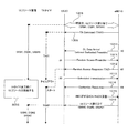
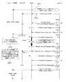
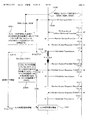
以下、上述したeNB10とUE20との間の基本的な接続処理の一例としてのコンテンションベースRA手順について、図2〜図4を用いて説明する。図2は、コンテンションベースRA手順の一例を示すシーケンス図である。図3は、UE20におけるコンテンションベースRA手順の一例を示すフローチャート、図4は、eNB10におけるコンテンションベースRA手順の一例を示すフローチャートである。
The UL
(1.3) Contention-Based RA Procedure Hereinafter, a contention-based RA procedure as an example of the basic connection process between the
コンテンションベースRA手順は、UE20においてULデータが発生した場合(UE20の初回送信時)や、UE20宛のDLデータがeNB10に到着してDLデータの着信通知がeNB10から受信された場合などに実行される。図3のフローチャートは、前者のケースを例示しており、図4のフローチャートは、後者のケースを例示している。
図3に例示するように、UE20において、ULデータが発生すると、UE20は、UL同期判定部24により、UL同期が確保されているか否かを判定する(処理1101〜処理1103)。
The contention-based RA procedure is executed when UL data is generated in the UE 20 (during the initial transmission of the UE 20), or when DL data addressed to the
As illustrated in FIG. 3, when UL data is generated in the
この判定の結果、UL同期が確保されていなければ(処理1103でnoであれば)、UE20は、ULリソース管理部26にて、予め用意されている複数のシグニチャ(プリアンブル)の中から1つを選択する。UE間で同一のシグニチャを選択する可能性を少しでも低下させる趣旨であり、発生させた乱数に応じて選択する等種々の選択方法を採用できる。選択したシグニチャは、メッセージ#1(RAプリアンブル)に含められて、送受信部22からRACHにてeNB10へ送信される(図2の処理1011及び図3の処理1104)。
As a result of this determination, if UL synchronization is not ensured (if no in processing 1103), the
eNB10は、前記メッセージ#1を受信すると、それに対する応答メッセージ#2(RAレスポンス)をUE20に送信する(図2の処理1012)。このRAレスポンス#2には、eNB10が受信(判別)できた1又は複数のシグニチャの識別子、当該シグニチャに対応するULの共有チャネルの送信許可、以降のRA通信の対象(UE20)を識別するために一時的に割り当てる識別子、などを含めることができる。この識別子は、temporary- connection radio network temporary identifier(T-CRNTI)と呼ばれる。
When receiving the
UE20は、eNB10からRAレスポンス#2を受信すると(図3の処理1105)、その受信情報に前記メッセージ#1で送信したシグニチャの識別子が含まれるか否かを確認する。
含まれる場合には、UE20は、当該RAレスポンス#2に含まれる、自身が送信したシグニチャに対応する送信許可に基づいて、メッセージ#3の送信(Scheduled Transmission)を行なう(図2の処理1013及び図3の処理1106)。このメッセージ#3は、eNB10に対するスケジューリング要求を含む信号であり、UE20の識別番号の一例としてのsystem architecture evolution(SAE)-temporary mobile subscriber identity(S−TMSI)などを含むことができる。
When the
If included, the
ここで、前記メッセージ#1で、UE20は、シグニチャを選択するが、複数のUE20が、同時に同じシグニチャを用いてメッセージ#1をeNB10に送信してしまうことも起こり得る。
その場合、eNB10では、それらのUE20を判別できないが、UE20が前記メッセージ#3で送信した識別情報(番号)(S−TMSI)を受信することで、どのUE20間でシグニチャの競合が発生したかを認識することができる。したがって、eNB10は、いずれか一のUE20を選択して競合解決することができる。この選択の基準には、メッセージ#1の受信電界強度を用いることができる。例えば、eNB10は、メッセージ#1の受信電界強度が他よりも大きいUE20を選択する。
Here, although the
In that case, the
eNB10は、競合解決により選択したUE20に対して、メッセージ#4(Contention Resolution)をUE20へ送信する(図2の処理1014)。このメッセージ#4には、メッセージ#3で送信したS−TMSIなどの情報を含めることができる。
UE20は、eNB10から前記メッセージ#4を受信すると(図3の処理1107)、他UE20との競合の有無をチェック(自身の識別情報が含まれているか否かチェック)し(図3の処理1108)、競合が生じていなければ、ULの接続処理は完了する(図3の処理1108のnoルート)。以後、UE20は、前記一時的に割り当てられた仮の識別子(T-CRNTI)を、確定的な識別子〔C(cell)-RNTI〕としてeNB10との通信に使用する。
The
Upon receiving the
一方、メッセージ#4を受信した結果、他UE20との競合が生じていた(自身の識別情報が含まれていない)場合(処理1108でyesの場合)、当該UE20は、前記バックオフで指定された時間だけ待機する(処理1111)。バックオフとは、UE20がコンテンションベースRA手順をリトライするタイミング(待機時間)を指定する情報である。
On the other hand, as a result of receiving the
バックオフのパラメータはメッセージ#2で通知され、UE20毎に、このバックオフを変えることで、リトライ時に再び競合が発生する確率を低減することができる。具体的には、メッセージ#2で最大バックオフ時間が通知され、UE20は、その時間の範囲内でバックオフ時間を算出する。この算出には、乱数を用いたりする等種々の算出方法を採用できる。
The back-off parameter is notified by
そして、UE20は、次回のRA手順のリトライによりリトライ回数が最大回数を超えるか否かをチェックする(処理1112)。超えなければ(処理1112でnoなら)、UE20は、前記処理1103以降の処理を実行して、RA手順をリトライする(メッセージ#1の送信を行なう)。超える場合(処理1112でyesの場合)は、UE20は、上位レイヤにその旨を通知する(処理1113)。前記上位レイヤは、例えば、レイヤ3に属するradio resource control(RRC)レイヤである。
Then, the
前記通知を受けた上位レイヤは、RAの継続(リトライ)を監視する監視タイマを起動する。この監視タイマがタイムアウトすると、UE20の上位レイヤは、ULの接続要求(メッセージ#1の送信)先のeNB10(セル)を選びなおす制御(セル選択制御、あるいはセル再選択制御)を実行する。
なお、前記の処理1103において、UL同期が確保されている場合(処理1103でyesの場合)、UE20は、PUCCHリソース(SRIリソース)が割り当て済みであるか否かをチェックする(処理1109)。割り当て済みであれば(処理1109でyesなら)、UE20は、SRIリソースを用いてSRI(ULデータの送信要求)をeNB10に送信する(処理1110)。
Upon receiving the notification, the upper layer starts a monitoring timer for monitoring RA continuation (retry). When this monitoring timer times out, the upper layer of the
In the
SRIリソースが割り当てられていなければ(処理1109でnoなら)、UE20は、eNB10に対するメッセージ#1の送信を行ない、RA手順を実行する。即ち、このように、処理1103において同期が確立されていると判定された場合であっても、SR PUCCHリソースが無い場合には、RA手順が実行されるケースも存在する。
一方、UE20宛のDLデータがeNB10に到着してDLデータの着信通知がeNB10からUE20になされる場合の、eNB10によるRA手順は、図4に例示するとおりである。
If the SRI resource is not allocated (if the
On the other hand, the RA procedure by the
すなわち、UE20宛のDLデータがeNB10に到着すると(処理1201)、eNB10は、UL同期判定部14により、UL同期が確保されているか否かを判定する(処理1202及び処理1203)。UL同期が確保されていなければ(処理1203でnoなら)、eNB10は、UE20にDLデータが到着したことを通知する(処理1204)。
That is, when the DL data addressed to the
この通知(着信通知)には、個別プリアンブルを含ませることもできるが、本実施例ではUE20に個別のシグニチャ(個別プリアンブル)は含まれない。そのため、前記着信通知を受けたUE20は、上述したコンテンションベースRA手順を実行することになる。その際、以前に割り当てられたULリソースがある場合、そのULリソースは解放され、RA成功後に新たなULリソースがeNB10から割り当てられる。
This notification (incoming notification) may include an individual preamble, but in this embodiment, the
eNB10は、コンテンションベースRA手順を開始したUE20からメッセージ#1(RAプリアンブル)を受信すると(処理1205)、その応答(メッセージ#2)をUE20に返信する(処理1206)。
そして、メッセージ#3をUE20から受信すると(処理1207)、eNB10は、メッセージの衝突があるか否かをチェックし(処理1208)、無ければメッセージ#4をUE20へ送信する(処理1208のnoルートから処理1209)。メッセージの衝突が有れば(処理1208でyesなら)、eNB10は、メッセージ#4の送信は行なわずにRA手順を終了する。
When the
When the
以上がコンテンションベースRAの基本的な手順である。ここで、eNB10が、UE20におけるTAタイマ251の値を正確に管理できていない(eNB10のTAタイマ151とUE20のTAタイマ251のタイマ値が同期していない)場合を想定する。
例示的に、UE20のTAタイマ251は計時を継続しているが、eNB10ではその継続を把握していないために、UE20のTAタイマ251はタイムアウトしているとeNB10が誤認識している場合を考える。
The above is the basic procedure of the contention base RA. Here, it is assumed that the
Exemplarily, the
その一例を図5〜図7(図9〜図11、図13〜図15、図17〜図19)に示す。eNB10は、UE20に対して呼設定及びULリソース(例えば、SRIリソース#1,CQIリソース#1,SRSリソース#1)の割当を行なうと(処理1008)、TAコマンドを周期的にUE20に送信する(処理1009)。このTAコマンド(TA値=TA#1;第1のタイミング調整情報)を受信したUE20は、TAタイマ251をスタートする。
Examples thereof are shown in FIGS. 5 to 7 (FIGS. 9 to 11, FIGS. 13 to 15, and FIGS. 17 to 19). When the
UE20が前記TAコマンドで通知されたTA#1に基づいてULの送信を行ない、その送信が終了した後、eNB10にUE20宛のDLデータが到着すると、eNB10は、UE20に対して着信通知(メッセージ#0の送信)を行なう(処理1010)。この着信通知#0を受けたUE20は、ULの同期とリソースとを確保するため、コンテンションベースRA手順を開始する。
When the
すなわち、UE20は、選択したシグニチャ(ランダムプリアンブル)を含むメッセージ#1をeNB10に送信し(処理1011)、このメッセージ#1を受信したeNB10は、RAレスポンス#2をUE20に返信する(処理1012)。その際、eNB10は、新しいTA値(TA#2;第2のタイミング調整情報)をRAレスポンス#2に含める。
That is, UE20 transmits
このRAレスポンス#2を受信したUE20は、新しいTA#2を適用してTAタイマ251をリスタートできるが、既述のように当該TA#2を無視することも許される。無視した場合、その後のメッセージ#3の送信(処理1013)とメッセージ#4の受信(処理1014)との間でTAタイマ251がタイムアウトする場合がある。
この場合に、UE20において、UL同期が外れたと判定して、それまでに確保しているULリソースのすべてを解放すると、以後、RACH以外のULデータの送信が不能になる。
The
In this case, if the
そこで、本例では、コンテンションベースRA手順の過程でTAタイマ251がタイムアウトした場合に、以下のようにして、UL同期とULリソースとを確保する。なお、以降の説明(後述する他の実施形態も含む)で用いる図面において、同一の処理番号を付した処理は、特に断らない限り、同一若しくは同様の処理を意味する。
(1.4)メッセージ#4の受信時に他UE20との競合が生じていなかった場合
他UE20との競合が生じていなかった場合(RAが成功した場合)、RAを実行したUE20に個別のULリソースが確保できたことを示す。しかし、TAタイマ251はタイムアウトした状態であるため、UL同期が確保できたとはいえない。
Therefore, in this example, when the
(1.4) When there is no contention with
そこで、UE20は、以下に示す4つの方法1−1〜1−4のいずれかを用いてUL同期を確保する。
(1.4.1)方法1−1(図5〜図8)
UE20は、図8に例示するように、コンテンションベースRA手順の過程で前記メッセージ#2により受信したTA値(TA#2)をタイマ管理部25のメモリ252に記憶しておく(処理1105a)。
Therefore, the
(1.4.1) Method 1-1 (FIGS. 5 to 8)
As illustrated in FIG. 8, the
なお、UE20(ULリソース管理部26)は、UL同期外れを認識した場合、コンテンションベースRAを開始する前に受信したTA#1に基づく送信処理に用いていた(RA開始前にeNB10から割り当てられた)ULリソースを解放することができる。
この解放のタイミングは、例えば、図5に例示するように、前記着信通知メッセージ#0を受信したタイミング(UL同期の管理がeNB10と一致していないことを認識したタイミング)(処理2001)でもよいし、図6に示すように、TAタイマ251がタイムアウトしたタイミング(処理2002)でもよい。ただし、図7に例示するように、TAタイマ251がタイムアウトしても、当該ULリソースの解放は行なわずに確保(継続使用)したままにすることもできる(処理2003)。
When the UE 20 (UL resource management unit 26) recognizes that UL synchronization has been lost, the UE 20 (UL resource management unit 26) used the transmission process based on
The release timing may be, for example, the timing at which the incoming call
その後、UE20は、コンテンションベースRA手順を継続して、メッセージ#4の受信に成功すると、UE20は、メモリ252に記憶したTA値(TA#2)をUL送信に適用するとともに、TAタイマ251をリスタートする(処理1108のnoルートから処理1114)。
つまり、TA#2の適用は、TAタイマ251のタイムアウト後、RAの過程においてUE20が、自身の識別情報の一例としてのT-CRNTIを含むメッセージ#2(応答信号)を受信したことを契機として許容される。なお、「TA値を適用する」とは、TA値で示される送信タイミングに基づいてULの送信(RAの実行)を制御することを意味する。この制御は、例えばUL同期判定部24の一機能として実現することができる(以降において同様)。
Thereafter, when the
In other words, the application of
この際、TAタイマ251の値は、規定値としてもよいし、メッセージ#2の受信タイミングに基づいて設定することもできる。例えば、UL同期はメッセージ#2の受信時に既に成功していたことにして、規定値からメッセージ#2の受信からメッセージ#4の受信までに要した時間を差し引いてTAタイマ251の値を設定してもよい。これは、メッセージ#2によりTA#2の通知を受けてからRAの結果が通知されるまでの時間だけタイマ値(タイミング調整情報の有効期限)を早めることを意味する。
At this time, the value of the
このように、本例では、UE20が、TA#1に基づいてeNB10に対するRAを行なっている場合に、そのRAの過程で、TA#2を受信すると、TAタイマ251のタイムアウト(TA#1の有効期限)までの送信処理に対しては、TA#1を送信タイミングの調整に適用する。TAタイマ251のタイムアウト後(TA#1の有効期限後)の送信処理に対しては、TA#2を送信タイミングの調整に適用する。
Thus, in this example, when the
これによれば、TA#2による送信タイミングの即時更新を行なわなくとも、TA#1の有効期限が過ぎた後(タイムアウトした後)、TA#2を適用して送信制御を行なうことができる。
その後、UE20は、メッセージ#4に対する確認応答メッセージ(ACK又はNACK)をeNB10に返信する(処理1015)。eNB10は、メッセージ#4に対する確認応答メッセージとしてACKを受信すれば、新たなULリソース(例えば、SRIリソース#2,CQIリソース#2,SRSリソース#2)をUE20に割り当てる(処理1016)。
According to this, it is possible to perform transmission control by applying
Then, UE20 returns the confirmation response message (ACK or NACK) with respect to
なお、図7に例示するように、UE20のTAタイマ251がタイムアウトしてもULリソースの解放を行なわない場合に、UE20は、既に確保しているULリソースを継続使用してもよいが、これに代わる新たなULリソースの割り当てをeNB10に要求することもできる(処理1017)。
UE20は、割り当てられたULリソースをULリソース管理部26において管理し、以後、当該ULリソースを用いてeNB10に対するUL送信を行なう。
As illustrated in FIG. 7, when the UL resource is not released even when the
The
(1.4.2)方法1−2(図9〜図12)
第2の方法として、図9〜図12に例示するように、UE20は、メッセージ#2で受信したTA値(TA#2)をメモリ252に記憶しておく(処理1105a)。その後、メッセージ#3の送信(処理1013)からメッセージ#4の受信(処理1014)までの間にTAタイマ251がタイムアウトしたとする。
(1.4.2) Method 1-2 (FIGS. 9 to 12)
As a second method, as illustrated in FIGS. 9 to 12, the
この場合、UE20は、メッセージ#4の受信を待たずに、メモリ252に記憶したTA値(TA#2)をUL送信に適用して、TAタイマ251をリスタートする(図12の処理1161のyesルートから処理1162)。リスタートのタイミングは、TAタイマ251のタイムアウトと同時としてよい。つまり、メッセージ#2で受信したTA#2の適用は、TAタイマ251のタイムアウト(TA#1の有効期限)のタイミングで許容される。
In this case, the
これによれば、TA#2による送信タイミングの即時更新を行なわなくとも、TA#1の有効期限が過ぎた時(タイムアウトした時)、TA#2を適用して送信制御を行なうことができる。
(1.4.3)方法1−3(図13〜図16)
第3の方法として、図13〜図16に例示するように、eNB10が、メッセージ#4を送信する際には、新しいTA値(TA#3)を含めることとする(図13〜図15の処理1014a、図16の処理1107a)。
According to this, even when the transmission timing is not immediately updated by
(14.3) Method 1-3 (FIGS. 13 to 16)
As a third method, as illustrated in FIGS. 13 to 16, when the
つまり、UE20が、TA#1(第1の送信タイミング調整情報)に基づいてeNB10に対するRAを行なっている場合に、そのRAの過程で、eNB10は、UE20に送信するメッセージ#4(UE20の識別情報の一例としてのS−TMSIを含む信号)に、TA#3(第2の送信タイミング調整情報)を含める。
UE20は、このメッセージ#4をeNB10から受信すると、当該メッセージ#4に含まれるTA値(TA#3)をUL送信に適用して、TAタイマ251をスタートする(図16の処理1114)。
That is, when the
When receiving this
即ち、通常であれば、移動局の識別情報が含まれるメッセージ#4には、TA値は含まれないが、この実施例では、メッセージ#4にTA値を含めることで、メッセージ#2で受信したTA#2を無視したUE20が、メッセージ#4のTA値をその後の送信タイミングの調整情報として適用し、TAタイマ251をスタートさせることができる。
なお、本例において、UE20は、前記無視したTA#2をメモリ252に記憶しておいてもよい。
That is, normally, the
In this example, the
(1.4.4)方法1−4(図17〜図20)
第4の方法として、図17〜図20に例示するように、UE20は、eNB10からメッセージ#2で受信したTA値(TA#2)を記憶するか否かに関わらず、メッセージ#2の受信を契機としてTAタイマ251をリスタートする。
この場合、UE20は、RA手順開始以前にeNB10から受信したTA値(TA#1)を、その後のRA(UL送信)に適用することを継続する(図20の処理1105b)。これは、RA開始前にeNB10からTAコマンドで受信したULの送信タイミングの有効期限をRAの過程で延長させるようTAタイマ251を制御することに相当する。
(1.4.4) Method 1-4 (FIGS. 17 to 20)
As a fourth method, as illustrated in FIGS. 17 to 20, the
In this case, the
つまり、UE20は、TA#1に基づいてeNB10に対するRAを行なっている場合に、そのRAの過程で、TA#2を受信すると、TA#2を適用せずに、TA#1を継続して適用するとともに、TA#1の有効期限を延長する。
なお、延長する期間(TA#2についてのTAタイマ251の値)は、規定値としてもよいし、メッセージ#2の受信タイミングに基づいて設定することもできる。例えば、UL同期はメッセージ#2の受信からTA#1のタイムアウトまでに要した時間を差し引いてTAタイマ251の値を設定してもよい。
That is, when the
Note that the period to be extended (the value of the
本例によれば、TA#2の受信後もTA#1を引き続き延長して利用することができ、送信タイミングの調整に適用することができる。
(1.5)メッセージ#4の受信時に他UE20との競合が生じていた場合
メッセージ#4の受信時に他UE20との競合が生じている場合は、他UE20が用いるULリソースとの重複が発生しており、自局20に個別のULリソースは確保できなかったことを意味する。
According to this example,
(1.5) When contention with other UE20 occurs when
そのため、UE20は、RACH以外のULのデータ送信を行なえないので、コンテンションベースRAのリトライを実行して、UL同期の確保を試みる(図3の処理1108のyesルート)。
〔2〕第2実施形態
上述した第1実施形態では、UE20がメッセージ#3を送信してからメッセージ#4をeNB10から受信するまでの間に、UE20のTAタイマ251がタイムアウトした場合を想定した。本実施形態では、UE20がeNB10からメッセージ#2を受信してからeNB10に対してメッセージ#3を送信するまでの間に、UE20のTAタイマ251がタイムアウトする場合を想定する。
For this reason, the
[2] Second Embodiment In the first embodiment described above, it is assumed that the
例えば、図21〜図23、図25〜図27及び図30〜図32に例示するように、eNB10にUE20宛のDLデータが到着して、UE20に着信通知(処理1010)が行なわれると、コンテンションベースRA(メッセージ#1の送信:処理1011)が実行される。この場合に、eNB10からメッセージ#2でTA値(TA#2)を受信したUE20が、当該TA#2を無視すると、メッセージ#3(UE20の識別情報の一例としてのS−TMSIを含む信号)の送信までにTAタイマ251がタイムアウトする場合がある。
For example, as illustrated in FIGS. 21 to 23, FIGS. 25 to 27, and FIGS. 30 to 32, when DL data addressed to the
このような場合、UE20(UL同期判定部24)は、UL同期が外れたと判定するが、以下の方法2−1〜2−4のいずれかにより、RAを継続する。
(2.1)方法2−1(図21〜図24)
UE20において、UL同期が外れたと判定した場合、本来的にはメッセージ#3の送信は行なえない。しかし、TAタイマ251は、物理レイヤにおけるUL同期が外れない範囲のフェイルセーフに設定される場合が多い。したがって、TAタイマ251がタイムアウトしても、実際の(下位レイヤの)UL同期は確保できている場合もある。
In such a case, the UE 20 (UL synchronization determination unit 24) determines that UL synchronization has been lost, but continues RA by any one of the following methods 2-1 to 2-4.
(2.1) Method 2-1 (FIGS. 21 to 24)
If the
そこで、本例では、UE20がeNB10からメッセージ#2を受信(処理1012)した後にTAタイマ251がタイムアウトしたとしても、当該UE20は、eNB10に対するメッセージ#3の送信(強制送信)を試行する(図21〜図23の処理1013a、図24の処理1105c及び処理1106a)。即ち、タイムアウトしたが、TA#1を適用してメッセージ#3を送信することができる。なお、TA#2は、メモリ252に記憶しておく。
Therefore, in this example, even if the
つまり、UE20は、TA#1に基づいてeNB10に対するRAを行なっている場合に、そのRAの過程で、TA#1の有効期限がメッセージ#3の送信処理を行なう前に到来すると、TA#1の有効期限の到来以前にTA#2を受信していたとしても、メッセージ#3のeNB10への送信処理をTA#1に基づいて実行することができる。
これにより、メッセージ#3をeNB10が受信できれば、UE20は、コンテンションベースRAを最初からやり直さずに、以後のRA手順を継続することが可能となる。即ち、UE20は、メッセージ#3に対する応答信号として自身の識別情報を含むメッセージ#4の受信に成功すれば、TA#2をその後の送信処理の送信タイミングの調整に適用して、TAタイマ251をスタートすることができる。したがって、ULデータ送信開始までの遅延を低減することができる。
That is, when the
As a result, if the
ただし、eNB10は、UE20がメッセージ#3を強制送信した、いわば規定違反を犯したことを認識できるので、メッセージ#4で接続拒否メッセージをUE20に送信することもできる。つまり、eNB10は、TA#1の有効期限が過ぎた後にUE20からTA#1に基づいて送信されたメッセージ#3を受信した場合に、拒否メッセージをUE20に送信することができる。
However, since the
この場合、UE20は、セル選択・再選択を実行したり、RA手順のリトライを実行する。あるいは、eNB10は、メッセージ#4を意図的に送信しないこともできる。この場合、UE20は、許容されている再送回数(通常の最大再送回数、あるいは、この場合のみに適用される最大再送回数)に達するまでメッセージ#3の再送を継続する。
(2.2)方法2−2(図25〜図28)
UE20は、図25〜図27に例示するように、メッセージ#2(TA#2)を受信(処理1012)した後、メッセージ#3をeNB10へ送信(処理1013)する前に、TAタイマ251が満了した場合、メッセージ#3の送信はキャンセルして、実行中のコンテンションベースRA手順を中止(キャンセル)する(処理1018)。
In this case, the
(2.2) Method 2-2 (FIGS. 25 to 28)
As illustrated in FIGS. 25 to 27, the
つまり、UE20は、TA#1に基づいてeNB10に対するRAを行なっている場合に、そのRAの過程で、TA#1の有効期限が、UE20の識別情報の一例としてのS−TMSIを含む信号の送信処理を行なう前に到来すると、TA#1の有効期限が到来する以前にTA#2を受信していても、RAを中止する。
この場合、UE20は、図28に例示するように、バックオフを適用して、コンテンションベースRAのリトライを実行する(処理1105dのyesルート)。すなわち、RAのリトライは、中止したRAの過程でeNB10から受信したバックオフ時間(待機時間情報)に基づくタイミングで実行される。UE20は、図25〜図27に例示するように、メッセージ#1の送信(処理1011)、メッセージ#2(TA#3)の受信(処理1012)などを行なう。
That is, when the
In this case, as illustrated in FIG. 28, the
ここで、メッセージ#2(TA#2)を受信した時点でTAタイマ251はタイムアウトしている(起動していない)。したがって、UE20は、リトライしたRAの過程でメッセージ#2により受信した新しいTA#3をその後のUL送信の送信タイミングの調整に適用して、TAタイマ251をスタートすることができる。メッセージ#4の受信時にRAの敗者であること(衝突発生)を認識した場合は、TAタイマ251は強制終了してよい(図25〜図27の処理2004)。
Here, when the message # 2 (TA # 2) is received, the
本例のように、TAタイマ251がタイムアウトした時点で、RA手順を中止してRAのリトライを実行することで、残りの手順(例えば、メッセージ#3の送信及びメッセージ#4の受信)を最後まで実施するよりも、ULデータ送信開始までの遅延を低減することができる。
(2.3)方法2−3(図25〜図27、図29)
なお、上述のごとくTAタイマ251がタイムアウトして、コンテンションベースRAをリトライする場合、図29に例示するように、UE20は、バックオフを適用せずに前記リトライを行なってもよい(処理1105dのyesルート)。
As shown in this example, when the
(2.3) Method 2-3 (FIGS. 25 to 27, FIG. 29)
As described above, when the
即ち、UE20は、RAのリトライを、中止したRAの過程でeNB10から受信したバックオフ時間を適用しないで実行することができる。バックオフを適用しないことで、バックオフを適用する場合よりもULデータ送信開始までの遅延を低減することが可能となる。
(2.4)方法2−4(図30〜図33)
また、図30〜図32に例示するように、TAタイマ251がタイムアウトした場合、UE20は、バックオフの適否に関わらず、上位レイヤ(例えば、RRCレイヤ)に通知を行なってもよい(処理1021、図33の処理1105dのyesルートから処理1113)。
That is, the
(2.4) Method 2-4 (FIGS. 30 to 33)
Further, as illustrated in FIGS. 30 to 32, when the
これにより、UE20の上位レイヤはRAの監視タイマを起動し、RA手順の継続(リトライ)を監視する。つまり、UE20は、TAタイマ251のタイムアウト(TA#1の有効期限の到来)に応じて、RAの監視を行なう。RAの継続中に、監視タイマがタイムアウトすると、UE20の上位レイヤは、セル選択、あるいはセル再選択処理を実行する(図30〜図32の処理1022)。
As a result, the upper layer of the
したがって、UE20は、早期に他のセル(eNB10)とのRAを開始することができ、ULデータ送信開始までの遅延を低減することができる。なお、TAタイマ251のタイムアウトに応じた上位レイヤによるRAの監視は、前記の方法2−1〜2−3に適用してもよい。
〔3〕第3実施形態
次に、本実施形態では、eNB10が、UE20におけるTAタイマ251のタイマ値を正確に管理できている場合(eNB10及びUE20の両TAタイマ151,251が同期している場合)を想定する。この場合、UE20のTAタイマ251の計時が継続していることを、eNB10は認識できるから、UE20は、eNB10から受信されるTA値を信頼してよい。さらに、第1実施形態および第2実施形態とは異なり、eNB10からTA値が送信されることが期待できる。
Therefore, UE20 can start RA with another cell (eNB10) at an early stage, and can reduce delay until UL data transmission start. The RA monitoring by the higher layer according to the timeout of the
[3] Third Embodiment Next, in this embodiment, when the
そして、UE20がTAコマンドにより受信したTA値に基づくULデータの送信を終了した後、eNB10にUE20宛のDLデータが到着すると、eNB10は、当該UE20に対して着信通知(メッセージ#0の送信)を行なう。
これにより、当該着信通知を受信したUE20は、コンテンションベースRA手順を開始する。その後、メッセージ#2の受信(処理1012)からメッセージ#3の送信(処理1013)までの間に、UE20のTAタイマ251がタイムアウトすると、UE20は、以下の方法3−1〜3−3のいずれかによりUL同期を確保する。
Then, after the transmission of UL data based on the TA value received by the
Thereby, UE20 which received the said notification of an incoming call starts a contention base RA procedure. Thereafter, when the
(3.1)方法3−1
UE20は、第1実施形態で述べた方法1−2(図9〜図12)と同様に、RA手順の過程でeNB10からメッセージ#2で受信したTA値をメモリ252に記憶しておく。そして、メッセージ#3をeNB10に送信する前にTAタイマ251がタイムアウトすると、メモリ252に記憶しておいたTA値をUL送信に適用して、TAタイマ251をスタートする。
(3.1) Method 3-1
The
(3.2)方法3−2
UE20は、第2実施形態で述べた方法2−1〜2−4のいずれかを実行する。
(3.3)方法3−3(図34〜図37)
図34及び図35に例示するように、UE20は、TA#1に基づいてeNB10に対するRAを行なっている場合に、そのRAの過程で、UE20の識別情報の一例としてのS−TMSIを含む信号(メッセージ#3)を送信する(処理1013)。
(3.2) Method 3-2
The
(3.3) Method 3-3 (FIGS. 34 to 37)
As illustrated in FIG. 34 and FIG. 35, when the
eNB10は、UE20のTAタイマ251がタイムアウトする前に、このメッセージ#3をUE20からRAの過程で受信すると(処理1013)、当該メッセージ#3の受信を契機として、新しいTA値(TA#3;第2のタイミング調整情報)を含むTAコマンドをUE20へ送信する(処理1009a、図36の処理1208a)。
一方、UE20は、RAの実行中においてもTAコマンドの受信を監視(モニタ)する。例えば、eNB10にメッセージ#3を送信(処理1013)した後は、eNB10からのTAコマンドの受信を監視する。この監視中に、TAコマンドをeNB10から受信すると(処理1009a、図37の処理1161)、UE20(タイマ管理部25)は、受信したTAコマンドのTA値(TA#3)をUL送信に適用して、TAタイマ251をスタートする(図37の処理1162)。
When the
On the other hand, the
なお、UE20におけるULリソースの管理は、第1又は第2実施形態と同様でよい。例えば、eNB10からDLデータの着信通知(メッセージ#0)を受信したタイミングで、それまでに確保しているULリソースを解放してもよいし、TAタイマ251がタイムアウトしたタイミングで当該ULリソースを解放してもよい。また、TAタイマ251がTA#3を受信する以前にタイムアウト(TA#1の有効期限が到来)しても、それまでに確保していたULリソースは解放せずに維持(継続使用)することも可能である(図35の処理2005)。
Note that management of UL resources in the
また、UE20は、メッセージ#3の送信からメッセージ#4の受信までの間に、TAタイマがタイムアウトした場合、第1実施形態と同様の形態(方法1−1〜方法1−4のいずれか)を適用することができる。
Further, when the TA timer times out between the transmission of
10 無線基地局(eNB)
11 送受信アンテナ
12 送受信部
13 バッファ部
14 UL同期判定部
15 タイマ管理部
151 UL同期タイマ(TAタイマ)
16 ULリソース管理部
20 無線端末(UE)
21 送受信アンテナ
22 送受信部
23 バッファ部
24 UL同期判定部
25 タイマ管理部
251 UL同期タイマ(TAタイマ)
252 メモリ
26 ULリソース管理部
10 Radio base station (eNB)
DESCRIPTION OF
16 UL
21 Transmission /
252
Claims (9)
前記移動局で、送信タイミング調整情報に基づいて、送信処理を行ない、
前記移動局と基地局との間で、送信処理に用いるPUCCH(Physical Uplink Control Channel)リソースに関する複数のパラメータを割り当て、
前記移動局で、第1の送信タイミング調整情報を有し前記基地局に対する接続処理を行なっている場合に、第2の送信タイミング調整情報の受信を含む該接続処理の過程で、該第1の送信タイミング調整情報の有効期限が、該移動局の識別情報を含む信号の送信を行なう前に到来すると、前記送信を行なわないと共に、割り当てられたPUCCHリソースに関する複数のパラメータの一部を解放する、
ことを特徴とする、タイミング調整方法。 In a timing adjustment method in a mobile communication system comprising a mobile station and a base station,
The mobile station performs transmission processing based on transmission timing adjustment information,
A plurality of parameters related to PUCCH (Physical Uplink Control Channel) resources used for transmission processing are allocated between the mobile station and the base station,
When the mobile station has first transmission timing adjustment information and is performing connection processing to the base station, in the course of the connection processing including reception of second transmission timing adjustment information, the first expiration of the transmission timing adjustment information and arrives before performing transmission of a signal including identification information of said mobile station, together with not performing the transmission, to release the part of the plurality of parameters related to the allocated PUCCH resources,
The timing adjustment method characterized by the above-mentioned.
前記移動局で、送信タイミング調整情報に基づいて、送信処理を行ない、
前記移動局と基地局との間で、送信処理に用いるPUCCH(Physical Uplink Control Channel)リソースに関する複数のパラメータを割り当て、
前記移動局で、第1の送信タイミング調整情報を有し前記基地局に対する接続処理を行なっている場合に、第2の送信タイミング調整情報の受信を含む該接続処理の過程で、該第1の送信タイミング調整情報の有効期限が、該移動局の識別情報を含む信号の送信を行なう前に到来すると、前記送信を行なわないと共に、SRI(Scheduling Request Indicator)に関わるパラメータ、CQI(Channel Quality Information)に関わるパラメータ、及びSRS(Sounding Reference Signal)に関わるパラメータをセットで解放する、
ことを特徴とする、タイミング調整方法。 In a timing adjustment method in a mobile communication system comprising a mobile station and a base station,
The mobile station performs transmission processing based on transmission timing adjustment information,
A plurality of parameters related to PUCCH (Physical Uplink Control Channel) resources used for transmission processing are allocated between the mobile station and the base station,
When the mobile station has first transmission timing adjustment information and is performing connection processing to the base station, in the course of the connection processing including reception of second transmission timing adjustment information, the first When the expiration date of the transmission timing adjustment information arrives before transmission of a signal including the identification information of the mobile station, the transmission is not performed, and parameters related to SRI (Scheduling Request Indicator), CQI (Channel Quality Information) Release parameters related to SRS and parameters related to SRS (Sounding Reference Signal) as a set.
The timing adjustment method characterized by the above-mentioned.
前記移動局は、
送信タイミング調整情報に基づいて、送信処理を行なう送信処理部と、
第1の送信タイミング調整情報を有し前記基地局に対する接続処理を行なっている場合に、第2の送信タイミング調整情報の受信を含む該接続処理の過程で、該第1の送信タイミング調整情報の有効期限が、該移動局の識別情報を含む信号の送信を行なう前に到来すると、前記送信を行なわないと共に、前記移動局と基地局との間で割り当てられる、送信処理に用いるPUCCH(Physical Uplink Control Channel)リソースに関する複数のパラメータについて、割り当てられたPUCCHリソースに関する複数のパラメータの一部を解放する制御部と、を備える
ことを特徴とする、移動通信システム。 In a mobile communication system comprising a mobile station and a base station,
The mobile station
A transmission processing unit that performs transmission processing based on the transmission timing adjustment information;
In the case of having the first transmission timing adjustment information and performing the connection process to the base station, in the course of the connection process including the reception of the second transmission timing adjustment information, the first transmission timing adjustment information When the expiration date comes before transmission of a signal including identification information of the mobile station, the transmission is not performed, and a PUCCH (Physical Uplink) used for transmission processing, which is allocated between the mobile station and the base station. for a plurality of parameters related to control Channel) resources, characterized in that it comprises a control unit for releasing part of a plurality of parameters related to PUCCH resources assigned, the mobile communication system.
前記移動局は、
送信タイミング調整情報に基づいて、送信処理を行なう送信処理部と、
第1の送信タイミング調整情報を有し前記基地局に対する接続処理を行なっている場合に、第2の送信タイミング調整情報の受信を含む該接続処理の過程で、該第1の送信タイミング調整情報の有効期限が、該移動局の識別情報を含む信号の送信を行なう前に到来すると、前記送信を行なわないと共に、前記移動局と基地局との間で割り当てられる、送信処理に用いるPUCCH(Physical Uplink Control Channel)リソースに関する複数のパラメータについて、SRI(Scheduling Request Indicator)に関わるパラメータ、CQI(Channel Quality Information)に関わるパラメータ、及びSRS(Sounding Reference Signal)に関わるパラメータをセットで解放する制御部と、を備える
ことを特徴とする、移動通信システム。 In a mobile communication system comprising a mobile station and a base station,
The mobile station
A transmission processing unit that performs transmission processing based on the transmission timing adjustment information;
In the case of having the first transmission timing adjustment information and performing the connection process to the base station, in the course of the connection process including the reception of the second transmission timing adjustment information, the first transmission timing adjustment information When the expiration date comes before transmission of a signal including identification information of the mobile station, the transmission is not performed, and a PUCCH (Physical Uplink) used for transmission processing, which is allocated between the mobile station and the base station. A plurality of parameters related to Control Channel) resources, a control unit that releases a parameter related to SRI (Scheduling Request Indicator), a parameter related to CQI (Channel Quality Information), and a parameter related to SRS (Sounding Reference Signal) in a set; A mobile communication system, comprising:
前記移動局と基地局との間で、送信処理に用いるPUCCHリソースに関する複数のパラメータを割り当てるUL(Uplink)リソース管理部、を備える
ことを特徴とする、請求項3又は請求項4に記載の移動通信システム。 The base station
The mobile according to claim 3 or 4, further comprising a UL (Uplink) resource management unit that allocates a plurality of parameters related to PUCCH resources used for transmission processing between the mobile station and the base station. Communications system.
送信タイミング調整情報に基づいて、送信処理を行なう送信処理部と、
第1の送信タイミング調整情報を有し前記基地局に対する接続処理を行なっている場合に、第2の送信タイミング調整情報の受信を含む該接続処理の過程で、該第1の送信タイミング調整情報の有効期限が、該移動局の識別情報を含む信号の送信を行なう前に到来すると、前記送信を行なわないと共に、前記移動局と基地局との間で割り当てられる、送信処理に用いるPUCCH(Physical Uplink Control Channel)リソースに関する複数のパラメータについて、割り当てられたPUCCHリソースに関する複数のパラメータの一部を解放する制御部と、を備える
ことを特徴とする、移動局。 The mobile station in a mobile communication system comprising a mobile station and a base station,
A transmission processing unit that performs transmission processing based on the transmission timing adjustment information;
In the case of having the first transmission timing adjustment information and performing the connection process to the base station, in the course of the connection process including the reception of the second transmission timing adjustment information, the first transmission timing adjustment information When the expiration date comes before transmission of a signal including identification information of the mobile station, the transmission is not performed, and a PUCCH (Physical Uplink) used for transmission processing, which is allocated between the mobile station and the base station. for a plurality of parameters related to control Channel) resources, characterized in that it comprises a control unit for releasing part of a plurality of parameters related to PUCCH resource allocated, the mobile station.
送信タイミング調整情報に基づいて、送信処理を行なう送信処理部と、
第1の送信タイミング調整情報を有し前記基地局に対する接続処理を行なっている場合に、第2の送信タイミング調整情報の受信を含む該接続処理の過程で、該第1の送信タイミング調整情報の有効期限が、該移動局の識別情報を含む信号の送信を行なう前に到来すると、前記送信を行なわないと共に、前記移動局と基地局との間で割り当てられる、送信処理に用いるPUCCH(Physical Uplink Control Channel)リソースに関する複数のパラメータについて、SRI(Scheduling Request Indicator)に関わるパラメータ、CQI(Channel Quality Information)に関わるパラメータ、及びSRS(Sounding Reference Signal)に関わるパラメータをセットで解放する制御部と、を備える
ことを特徴とする、移動局。 The mobile station in a mobile communication system comprising a mobile station and a base station,
A transmission processing unit that performs transmission processing based on the transmission timing adjustment information;
In the case of having the first transmission timing adjustment information and performing the connection process to the base station, in the course of the connection process including the reception of the second transmission timing adjustment information, the first transmission timing adjustment information When the expiration date comes before transmission of a signal including identification information of the mobile station, the transmission is not performed, and a PUCCH (Physical Uplink) used for transmission processing, which is allocated between the mobile station and the base station. A plurality of parameters related to Control Channel) resources, a control unit that releases a parameter related to SRI (Scheduling Request Indicator), a parameter related to CQI (Channel Quality Information), and a parameter related to SRS (Sounding Reference Signal) in a set; A mobile station comprising a mobile station.
前記移動局と基地局との間で、送信処理に用いるPUCCH(Physical Uplink Control Channel)リソースに関する複数のパラメータを割り当てるUL(Uplink)リソース管理部、を備えると共に、
送信タイミング調整情報に基づいて、送信処理を行なう送信処理部と、
第1の送信タイミング調整情報を有し前記基地局に対する接続処理を行なっている場合に、第2の送信タイミング調整情報の受信を含む該接続処理の過程で、該第1の送信タイミング調整情報の有効期限が、該移動局の識別情報を含む信号の送信を行なう前に到来すると、前記送信を行なわないと共に、割り当てられたPUCCHリソースに関する複数のパラメータの一部を解放する制御部と、
を有する前記移動局から送信された信号を受信する受信処理部、を備える
ことを特徴とする、基地局。 The base station in a mobile communication system comprising a mobile station and a base station,
A UL (Uplink) resource management unit that allocates a plurality of parameters related to PUCCH (Physical Uplink Control Channel) resources used for transmission processing between the mobile station and the base station;
A transmission processing unit that performs transmission processing based on the transmission timing adjustment information;
In the case of having the first transmission timing adjustment information and performing the connection process to the base station, in the course of the connection process including the reception of the second transmission timing adjustment information, the first transmission timing adjustment information expiration date and arrives before performing transmission of a signal including identification information of said mobile station, together with not performing the transmission, and a control unit for releasing part of a plurality of parameters related to PUCCH resources assigned,
A base station, comprising: a reception processing unit that receives a signal transmitted from the mobile station.
前記移動局と基地局との間で、送信処理に用いるPUCCH(Physical Uplink Control Channel)リソースに関する複数のパラメータを割り当てるUL(Uplink)リソース管理部、を備えると共に、
送信タイミング調整情報に基づいて、送信処理を行なう送信処理部と、
第1の送信タイミング調整情報を有し前記基地局に対する接続処理を行なっている場合に、第2の送信タイミング調整情報の受信を含む該接続処理の過程で、該第1の送信タイミング調整情報の有効期限が、該移動局の識別情報を含む信号の送信を行なう前に到来すると、前記送信を行なわないと共に、SRI(Scheduling Request Indicator)に関わるパラメータ、CQI(Channel Quality Information)に関わるパラメータ、及びSRS(Sounding Reference Signal)に関わるパラメータをセットで解放する制御部と、
を有する前記移動局から送信された信号を受信する受信処理部、を備える
ことを特徴とする、基地局。 The base station in a mobile communication system comprising a mobile station and a base station,
A UL (Uplink) resource management unit that allocates a plurality of parameters related to PUCCH (Physical Uplink Control Channel) resources used for transmission processing between the mobile station and the base station;
A transmission processing unit that performs transmission processing based on the transmission timing adjustment information;
In the case of having the first transmission timing adjustment information and performing the connection process to the base station, in the course of the connection process including the reception of the second transmission timing adjustment information, the first transmission timing adjustment information If the expiration date arrives before transmission of a signal including identification information of the mobile station, the transmission is not performed, parameters related to SRI (Scheduling Request Indicator), parameters related to CQI (Channel Quality Information), and A control unit for releasing parameters related to SRS (Sounding Reference Signal) as a set;
A base station, comprising: a reception processing unit that receives a signal transmitted from the mobile station.
Priority Applications (1)
| Application Number | Priority Date | Filing Date | Title |
|---|---|---|---|
| JP2011052981A JP5240310B2 (en) | 2011-03-10 | 2011-03-10 | Timing adjustment method, mobile station, base station, and mobile communication system |
Applications Claiming Priority (1)
| Application Number | Priority Date | Filing Date | Title |
|---|---|---|---|
| JP2011052981A JP5240310B2 (en) | 2011-03-10 | 2011-03-10 | Timing adjustment method, mobile station, base station, and mobile communication system |
Related Parent Applications (1)
| Application Number | Title | Priority Date | Filing Date |
|---|---|---|---|
| JP2010515679A Division JP5003820B2 (en) | 2008-06-02 | 2008-06-02 | Timing adjustment method, mobile station, and mobile communication system |
Related Child Applications (6)
| Application Number | Title | Priority Date | Filing Date |
|---|---|---|---|
| JP2012175790A Division JP5223990B2 (en) | 2012-08-08 | 2012-08-08 | Timing adjustment method, mobile station, base station, and mobile communication system |
| JP2012229338A Division JP5472422B2 (en) | 2012-10-16 | 2012-10-16 | Timing adjustment method, mobile communication system, mobile station, and base station |
| JP2012229339A Division JP5240393B2 (en) | 2012-10-16 | 2012-10-16 | Uplink transmission control method, mobile communication system, mobile station, and base station |
| JP2012229337A Division JP5472421B2 (en) | 2012-10-16 | 2012-10-16 | Timing adjustment method, mobile communication system, mobile station, and base station |
| JP2013077672A Division JP5288075B2 (en) | 2013-04-03 | 2013-04-03 | Uplink transmission control method, mobile communication system, mobile station, and base station |
| JP2013077673A Division JP5288076B2 (en) | 2013-04-03 | 2013-04-03 | Uplink transmission control method, mobile communication system, mobile station, and base station |
Publications (2)
| Publication Number | Publication Date |
|---|---|
| JP2011109730A JP2011109730A (en) | 2011-06-02 |
| JP5240310B2 true JP5240310B2 (en) | 2013-07-17 |
Family
ID=44232620
Family Applications (1)
| Application Number | Title | Priority Date | Filing Date |
|---|---|---|---|
| JP2011052981A Active JP5240310B2 (en) | 2011-03-10 | 2011-03-10 | Timing adjustment method, mobile station, base station, and mobile communication system |
Country Status (1)
| Country | Link |
|---|---|
| JP (1) | JP5240310B2 (en) |
-
2011
- 2011-03-10 JP JP2011052981A patent/JP5240310B2/en active Active
Also Published As
| Publication number | Publication date |
|---|---|
| JP2011109730A (en) | 2011-06-02 |
Similar Documents
| Publication | Publication Date | Title |
|---|---|---|
| JP5003820B2 (en) | Timing adjustment method, mobile station, and mobile communication system | |
| JP5412426B2 (en) | Connection processing method, radio base station, and radio terminal in radio communication system | |
| WO2010142852A1 (en) | Method and apparatus for facilitating relay node communications | |
| JP5288075B2 (en) | Uplink transmission control method, mobile communication system, mobile station, and base station | |
| JP5240310B2 (en) | Timing adjustment method, mobile station, base station, and mobile communication system | |
| JP5472421B2 (en) | Timing adjustment method, mobile communication system, mobile station, and base station | |
| JP5288076B2 (en) | Uplink transmission control method, mobile communication system, mobile station, and base station | |
| JP5223990B2 (en) | Timing adjustment method, mobile station, base station, and mobile communication system | |
| JP5240393B2 (en) | Uplink transmission control method, mobile communication system, mobile station, and base station | |
| JP5472422B2 (en) | Timing adjustment method, mobile communication system, mobile station, and base station |
Legal Events
| Date | Code | Title | Description |
|---|---|---|---|
| A621 | Written request for application examination |
Free format text: JAPANESE INTERMEDIATE CODE: A621 Effective date: 20110310 |
|
| A131 | Notification of reasons for refusal |
Free format text: JAPANESE INTERMEDIATE CODE: A131 Effective date: 20120821 |
|
| A521 | Written amendment |
Free format text: JAPANESE INTERMEDIATE CODE: A523 Effective date: 20121016 |
|
| A131 | Notification of reasons for refusal |
Free format text: JAPANESE INTERMEDIATE CODE: A131 Effective date: 20121113 |
|
| A521 | Written amendment |
Free format text: JAPANESE INTERMEDIATE CODE: A523 Effective date: 20130111 |
|
| TRDD | Decision of grant or rejection written | ||
| A01 | Written decision to grant a patent or to grant a registration (utility model) |
Free format text: JAPANESE INTERMEDIATE CODE: A01 Effective date: 20130305 |
|
| A61 | First payment of annual fees (during grant procedure) |
Free format text: JAPANESE INTERMEDIATE CODE: A61 Effective date: 20130318 |
|
| FPAY | Renewal fee payment (event date is renewal date of database) |
Free format text: PAYMENT UNTIL: 20160412 Year of fee payment: 3 |
|
| R150 | Certificate of patent or registration of utility model |
Free format text: JAPANESE INTERMEDIATE CODE: R150 Ref document number: 5240310 Country of ref document: JP Free format text: JAPANESE INTERMEDIATE CODE: R150 |