JP5240245B2 - Channel switching device, processing device, channel switching method and processing method, and storage medium - Google Patents
Channel switching device, processing device, channel switching method and processing method, and storage medium Download PDFInfo
- Publication number
- JP5240245B2 JP5240245B2 JP2010141921A JP2010141921A JP5240245B2 JP 5240245 B2 JP5240245 B2 JP 5240245B2 JP 2010141921 A JP2010141921 A JP 2010141921A JP 2010141921 A JP2010141921 A JP 2010141921A JP 5240245 B2 JP5240245 B2 JP 5240245B2
- Authority
- JP
- Japan
- Prior art keywords
- flow path
- processing
- outer cylinder
- cylinder
- connection
- Prior art date
- Legal status (The legal status is an assumption and is not a legal conclusion. Google has not performed a legal analysis and makes no representation as to the accuracy of the status listed.)
- Active
Links
- 238000012545 processing Methods 0.000 title claims description 197
- 238000000034 method Methods 0.000 title claims description 21
- 238000003672 processing method Methods 0.000 title claims description 10
- 238000003860 storage Methods 0.000 title claims description 10
- 239000012530 fluid Substances 0.000 claims description 59
- 230000002093 peripheral effect Effects 0.000 claims description 11
- 238000007599 discharging Methods 0.000 claims description 10
- 238000004590 computer program Methods 0.000 claims description 4
- 239000007788 liquid Substances 0.000 description 126
- 235000012431 wafers Nutrition 0.000 description 74
- 239000000126 substance Substances 0.000 description 55
- KFZMGEQAYNKOFK-UHFFFAOYSA-N Isopropanol Chemical compound CC(C)O KFZMGEQAYNKOFK-UHFFFAOYSA-N 0.000 description 36
- 239000000243 solution Substances 0.000 description 32
- 230000007246 mechanism Effects 0.000 description 26
- 230000002378 acidificating effect Effects 0.000 description 12
- 238000004140 cleaning Methods 0.000 description 10
- 238000001035 drying Methods 0.000 description 8
- 239000007789 gas Substances 0.000 description 5
- 239000003595 mist Substances 0.000 description 5
- KRHYYFGTRYWZRS-UHFFFAOYSA-N Fluorane Chemical compound F KRHYYFGTRYWZRS-UHFFFAOYSA-N 0.000 description 4
- FFUAGWLWBBFQJT-UHFFFAOYSA-N hexamethyldisilazane Chemical compound C[Si](C)(C)N[Si](C)(C)C FFUAGWLWBBFQJT-UHFFFAOYSA-N 0.000 description 4
- 230000015572 biosynthetic process Effects 0.000 description 3
- 239000000356 contaminant Substances 0.000 description 3
- 239000002245 particle Substances 0.000 description 3
- QGZKDVFQNNGYKY-UHFFFAOYSA-N Ammonia Chemical compound N QGZKDVFQNNGYKY-UHFFFAOYSA-N 0.000 description 2
- MHAJPDPJQMAIIY-UHFFFAOYSA-N Hydrogen peroxide Chemical compound OO MHAJPDPJQMAIIY-UHFFFAOYSA-N 0.000 description 2
- 239000004743 Polypropylene Substances 0.000 description 2
- 238000012993 chemical processing Methods 0.000 description 2
- 230000000694 effects Effects 0.000 description 2
- 238000009434 installation Methods 0.000 description 2
- 238000004519 manufacturing process Methods 0.000 description 2
- -1 polypropylene Polymers 0.000 description 2
- 229920001155 polypropylene Polymers 0.000 description 2
- 229920001343 polytetrafluoroethylene Polymers 0.000 description 2
- 239000004810 polytetrafluoroethylene Substances 0.000 description 2
- 239000004065 semiconductor Substances 0.000 description 2
- 238000010129 solution processing Methods 0.000 description 2
- 238000011144 upstream manufacturing Methods 0.000 description 2
- XLYOFNOQVPJJNP-UHFFFAOYSA-N water Substances O XLYOFNOQVPJJNP-UHFFFAOYSA-N 0.000 description 2
- UGFAIRIUMAVXCW-UHFFFAOYSA-N Carbon monoxide Chemical compound [O+]#[C-] UGFAIRIUMAVXCW-UHFFFAOYSA-N 0.000 description 1
- 229910021529 ammonia Inorganic materials 0.000 description 1
- 239000007864 aqueous solution Substances 0.000 description 1
- 239000000969 carrier Substances 0.000 description 1
- 239000000470 constituent Substances 0.000 description 1
- 238000001514 detection method Methods 0.000 description 1
- 239000006185 dispersion Substances 0.000 description 1
- 238000006073 displacement reaction Methods 0.000 description 1
- 239000003814 drug Substances 0.000 description 1
- 230000002209 hydrophobic effect Effects 0.000 description 1
- 239000000463 material Substances 0.000 description 1
- 239000011259 mixed solution Substances 0.000 description 1
- 230000003287 optical effect Effects 0.000 description 1
- 239000004800 polyvinyl chloride Substances 0.000 description 1
- 230000007723 transport mechanism Effects 0.000 description 1
- 239000002351 wastewater Substances 0.000 description 1
Images


Classifications
-
- H—ELECTRICITY
- H01—ELECTRIC ELEMENTS
- H01L—SEMICONDUCTOR DEVICES NOT COVERED BY CLASS H10
- H01L21/00—Processes or apparatus adapted for the manufacture or treatment of semiconductor or solid state devices or of parts thereof
- H01L21/67—Apparatus specially adapted for handling semiconductor or electric solid state devices during manufacture or treatment thereof; Apparatus specially adapted for handling wafers during manufacture or treatment of semiconductor or electric solid state devices or components ; Apparatus not specifically provided for elsewhere
- H01L21/67005—Apparatus not specifically provided for elsewhere
- H01L21/67011—Apparatus for manufacture or treatment
- H01L21/67017—Apparatus for fluid treatment
- H01L21/67028—Apparatus for fluid treatment for cleaning followed by drying, rinsing, stripping, blasting or the like
-
- H—ELECTRICITY
- H01—ELECTRIC ELEMENTS
- H01L—SEMICONDUCTOR DEVICES NOT COVERED BY CLASS H10
- H01L21/00—Processes or apparatus adapted for the manufacture or treatment of semiconductor or solid state devices or of parts thereof
- H01L21/02—Manufacture or treatment of semiconductor devices or of parts thereof
- H01L21/04—Manufacture or treatment of semiconductor devices or of parts thereof the devices having at least one potential-jump barrier or surface barrier, e.g. PN junction, depletion layer or carrier concentration layer
- H01L21/18—Manufacture or treatment of semiconductor devices or of parts thereof the devices having at least one potential-jump barrier or surface barrier, e.g. PN junction, depletion layer or carrier concentration layer the devices having semiconductor bodies comprising elements of Group IV of the Periodic System or AIIIBV compounds with or without impurities, e.g. doping materials
- H01L21/30—Treatment of semiconductor bodies using processes or apparatus not provided for in groups H01L21/20 - H01L21/26
- H01L21/302—Treatment of semiconductor bodies using processes or apparatus not provided for in groups H01L21/20 - H01L21/26 to change their surface-physical characteristics or shape, e.g. etching, polishing, cutting
-
- H—ELECTRICITY
- H01—ELECTRIC ELEMENTS
- H01L—SEMICONDUCTOR DEVICES NOT COVERED BY CLASS H10
- H01L21/00—Processes or apparatus adapted for the manufacture or treatment of semiconductor or solid state devices or of parts thereof
- H01L21/67—Apparatus specially adapted for handling semiconductor or electric solid state devices during manufacture or treatment thereof; Apparatus specially adapted for handling wafers during manufacture or treatment of semiconductor or electric solid state devices or components ; Apparatus not specifically provided for elsewhere
- H01L21/67005—Apparatus not specifically provided for elsewhere
- H01L21/67011—Apparatus for manufacture or treatment
- H01L21/67155—Apparatus for manufacturing or treating in a plurality of work-stations
- H01L21/67161—Apparatus for manufacturing or treating in a plurality of work-stations characterized by the layout of the process chambers
- H01L21/67173—Apparatus for manufacturing or treating in a plurality of work-stations characterized by the layout of the process chambers in-line arrangement
-
- Y—GENERAL TAGGING OF NEW TECHNOLOGICAL DEVELOPMENTS; GENERAL TAGGING OF CROSS-SECTIONAL TECHNOLOGIES SPANNING OVER SEVERAL SECTIONS OF THE IPC; TECHNICAL SUBJECTS COVERED BY FORMER USPC CROSS-REFERENCE ART COLLECTIONS [XRACs] AND DIGESTS
- Y10—TECHNICAL SUBJECTS COVERED BY FORMER USPC
- Y10T—TECHNICAL SUBJECTS COVERED BY FORMER US CLASSIFICATION
- Y10T137/00—Fluid handling
- Y10T137/0318—Processes
- Y10T137/0324—With control of flow by a condition or characteristic of a fluid
-
- Y—GENERAL TAGGING OF NEW TECHNOLOGICAL DEVELOPMENTS; GENERAL TAGGING OF CROSS-SECTIONAL TECHNOLOGIES SPANNING OVER SEVERAL SECTIONS OF THE IPC; TECHNICAL SUBJECTS COVERED BY FORMER USPC CROSS-REFERENCE ART COLLECTIONS [XRACs] AND DIGESTS
- Y10—TECHNICAL SUBJECTS COVERED BY FORMER USPC
- Y10T—TECHNICAL SUBJECTS COVERED BY FORMER US CLASSIFICATION
- Y10T137/00—Fluid handling
- Y10T137/8593—Systems
- Y10T137/87571—Multiple inlet with single outlet
- Y10T137/87676—With flow control
- Y10T137/87684—Valve in each inlet
-
- Y—GENERAL TAGGING OF NEW TECHNOLOGICAL DEVELOPMENTS; GENERAL TAGGING OF CROSS-SECTIONAL TECHNOLOGIES SPANNING OVER SEVERAL SECTIONS OF THE IPC; TECHNICAL SUBJECTS COVERED BY FORMER USPC CROSS-REFERENCE ART COLLECTIONS [XRACs] AND DIGESTS
- Y10—TECHNICAL SUBJECTS COVERED BY FORMER USPC
- Y10T—TECHNICAL SUBJECTS COVERED BY FORMER US CLASSIFICATION
- Y10T137/00—Fluid handling
- Y10T137/8593—Systems
- Y10T137/877—With flow control means for branched passages
- Y10T137/87877—Single inlet with multiple distinctly valved outlets
Landscapes
- Engineering & Computer Science (AREA)
- Physics & Mathematics (AREA)
- Condensed Matter Physics & Semiconductors (AREA)
- General Physics & Mathematics (AREA)
- Manufacturing & Machinery (AREA)
- Computer Hardware Design (AREA)
- Microelectronics & Electronic Packaging (AREA)
- Power Engineering (AREA)
- Cleaning Or Drying Semiconductors (AREA)
- Multiple-Way Valves (AREA)
Description
本発明は、各々が独立した流体を流すための複数の接続用流路を、当該接続用流路に対して接続される共通流路に切替え接続するための流路切替え装置及び流路切替え方法、及びこの流路切替え装置を備えた処理装置及び処理方法に関する。 The present invention relates to a flow path switching device and a flow path switching method for switching and connecting a plurality of connection flow paths for flowing independent fluids to a common flow path connected to the connection flow path. The present invention also relates to a processing apparatus and a processing method including the flow path switching device.
半導体デバイスなどの製造工程には、半導体ウエハ(以下、ウエハという)などの被処理体の表面に薬液や純水などの処理液を供給してウエハWに付着したパーティクルや汚染物質の除去を行う液処理がある。こうした液処理を行う液処理装置の一つに、ウエハWを回転させながら当該ウエハWの表面に処理液を供給して液処理を実行する液処理装置がある。この種の液処理装置では、単位時間当たりのウエハWの処理枚数(スループット)を向上させるために、例えば同種の液処理を実行可能な複数例えば4〜5台の液処理ユニットを用意し、共通の搬送機構を用いてウエハWを搬送することにより、複数の液処理ユニットにて並行して液処理を実行することが行われている。 In the manufacturing process of a semiconductor device or the like, particles and contaminants attached to the wafer W are removed by supplying a processing solution such as a chemical solution or pure water to the surface of an object to be processed such as a semiconductor wafer (hereinafter referred to as a wafer). There is liquid treatment. One liquid processing apparatus that performs such liquid processing is a liquid processing apparatus that performs liquid processing by supplying a processing liquid to the surface of the wafer W while rotating the wafer W. In this type of liquid processing apparatus, in order to improve the number of wafers W processed per unit time (throughput), for example, a plurality of, for example, 4 to 5 liquid processing units capable of executing the same type of liquid processing are prepared. The liquid processing is performed in parallel by a plurality of liquid processing units by transporting the wafer W using the transport mechanism.
前記液処理ユニットは、例えば図16に示すように、ウエハWを載置して回転させるスピンチャック11と、スピンチャック11上のウエハWを囲むように設けられたカップ12と、を備えている。前記処理液としては、酸性薬液やアルカリ性薬液等が用いられており、処理に応じて図示しないノズルから薬液を切替えてウエハWに供給するように構成されている。
For example, as shown in FIG. 16, the liquid processing unit includes a
ここで、特許文献1には、複数の液処理ユニットを水平に配置すると共に、酸性薬液専用の排気ライン及びアルカリ性薬液専用の排気ラインを備える構成が記載されている。この場合、例えば図16に示すように、夫々の液処理ユニットのカップ12は、酸性薬液専用の排気ライン13及びアルカリ薬液専用の排気ライン14と夫々専用の排気路15,16により接続される。これら排気路15,16には、夫々バルブV15,V16が設けられており、薬液に応じてこのバルブV15,V16を開閉することによって、カップ12内の雰囲気を専用の排気ライン13,14を介して排気するように構成されている。
Here, Patent Document 1, as well as arranging a plurality of liquid processing units horizontally, configuration including the exhaust line and alkaline chemical dedicated exhaust line for acidic chemical dedicated is described. In this case, for example, as shown in FIG. 16, the
しかしながら、このような構成では、1つの液処理ユニットにおいて、専用排気路15,16毎に夫々バルブV15,16が必要であり、薬液の種類が多くなる程、バルブの設置数が多くなってしまう。また、バルブが増加すれば、バルブの駆動部も多くなるため、調整に時間がかかり、またバルブや駆動部が占有するスペースが大きなものとなってしまう。 However, in such a configuration, in one liquid processing unit, the valves V15 and V16 are required for the dedicated exhaust passages 15 and 16, respectively, and the more kinds of chemical solutions, the more valves are installed. . In addition, if the number of valves increases, the number of drive parts of the valves increases, so that adjustment takes time and the space occupied by the valves and drive parts becomes large.
本発明はこのような事情に鑑みてなされたものであり、本発明の目的は、流路を切替えるための駆動機構の個数を削減することができる流路切替え装置及び流路切替え方法を提供することにある。本発明の他の目的は、被処理体を処理する処理流体の専用排出路を切替えるための駆動機構の個数を削減することができる処理装置及び処理方法を提供することにある。 The present invention has been made in view of such circumstances, and an object of the present invention is to provide a flow path switching device and a flow path switching method capable of reducing the number of drive mechanisms for switching flow paths. There is. Another object of the present invention is to provide a processing apparatus and a processing method capable of reducing the number of drive mechanisms for switching a dedicated discharge path for a processing fluid for processing an object to be processed.
このため本発明は、各々が独立した流体を流すための複数の接続用流路を、当該接続用流路に対して接続される共通流路に切替え接続するための流路切替え装置において、
外筒と、
この外筒の周壁に当該外筒の長さ方向に沿って間隔をおいて開口し、前記複数の接続用流路に夫々接続される複数の接続口と、
前記共通流路に接続される接続口が設けられ、外筒内に回転自在に挿入された回転筒と、
この回転筒の周壁に当該回転筒の長さ方向に沿って間隔をおいて前記外筒の複数の接続口に対応する位置に夫々形成された複数の開口部と、
前記回転筒を回転させるための回転駆動部と、を備え、
前記外筒の軸方向を前後方向とすると、当該外筒の一端側から他端側を見て、前記複数の接続口のいずれもが左側に開口するか、または前記複数の接続口のいずれもが右側に開口し、
前記回転筒の複数の開口部は、当該回転筒を回転する間に、互いに対応する外筒の接続口と回転筒の開口部との組の一つが重なり合って連通し、かつ他の組については連通しない状態が各組の間で順番に起こるように配置されていることを特徴とする
Therefore, the present invention provides a flow path switching device for switching and connecting a plurality of connection flow paths for flowing independent fluids to a common flow path connected to the connection flow path.
An outer cylinder,
A plurality of connection ports that are opened at intervals along the length direction of the outer cylinder on the peripheral wall of the outer cylinder, and are connected to the plurality of connection flow paths, respectively.
A rotary cylinder provided with a connection port connected to the common flow path and rotatably inserted into the outer cylinder;
A plurality of openings respectively formed at positions corresponding to a plurality of connection ports of the outer cylinder at intervals along the length direction of the rotating cylinder on the peripheral wall of the rotating cylinder;
A rotation driving unit for rotating the rotating cylinder,
When the axial direction of the outer cylinder is the front-rear direction, all of the plurality of connection ports open to the left side when viewed from one end side to the other end side of the outer cylinder, or any of the plurality of connection ports Opens to the right,
The plurality of openings of the rotating cylinder communicate with each other by overlapping one of the pairs of the connection ports of the outer cylinder and the opening of the rotating cylinder while rotating the rotating cylinder. It is arranged so that the state that does not communicate occurs in order between each pair
また、本発明の処理装置は、
被処理体に対して複数種別の処理流体を互いに異なるタイミングで供給しながら処理を行う処理部と、
この処理部へ供給された複数種別の処理流体を排出するために、前記処理部に設けられた共通流路と、
前記複数種別の処理流体毎に設けられ、前記処理流体を排出するための複数の専用排出路と、
前記共通流路を、前記処理流体の種別に対応した専用排出路に切替え接続するための流路切替え装置と、を備え、
前記流路切替え装置は、前記流路切替え装置であることを特徴とする。
The processing apparatus of the present invention is
A processing unit that performs processing while supplying a plurality of types of processing fluids to the target object at different timings;
To discharge a plurality of types of processing fluids supplied to the processing unit, a common flow path provided in the processing unit,
A plurality of dedicated discharge paths provided for each of the plurality of types of processing fluids, for discharging the processing fluids;
A flow path switching device for switching and connecting the common flow path to a dedicated discharge path corresponding to the type of the processing fluid,
The channel switching device is the channel switching device.
さらに他の発明は、各々が独立した流体を流すための複数の接続用流路を、当該接続用流路に対して接続される共通流路に切替え接続するための流路切替え方法において、
外筒と、
この外筒の周壁に当該外筒の長さ方向に沿って間隔をおいて開口し、前記複数の接続用流路に夫々接続される複数の接続口と、
前記共通流路に接続される接続口が設けられ、外筒内に回転自在に挿入された回転筒と、
この回転筒の周壁に当該回転筒の長さ方向に沿って間隔をおいて前記外筒の複数の接続口に対応する位置に夫々形成された複数の開口部と、を備え、
前記外筒の軸方向を前後方向とすると、当該外筒の一端側から他端側を見て、前記複数の接続口のいずれもが左側に開口するか、または前記複数の接続口のいずれもが右側に開口した流路切替え装置を用い、
前記回転筒を回転する間に、互いに対応する外筒の接続口と回転筒の開口部との組の一つが重なり合って連通し、かつ他の組については連通しない状態を形成して流路の切替え接続を行うことを特徴とする。
Still another invention is a flow path switching method for switching and connecting a plurality of connection flow paths for flowing independent fluids to a common flow path connected to the connection flow path.
An outer cylinder,
A plurality of connection ports that are opened at intervals along the length direction of the outer cylinder on the peripheral wall of the outer cylinder, and are connected to the plurality of connection flow paths, respectively.
A rotary cylinder provided with a connection port connected to the common flow path and rotatably inserted into the outer cylinder;
A plurality of openings formed respectively at positions corresponding to the plurality of connection ports of the outer cylinder at intervals along the length direction of the rotating cylinder on the peripheral wall of the rotating cylinder ,
When the axial direction of the outer cylinder is the front-rear direction, all of the plurality of connection ports open to the left side when viewed from one end side to the other end side of the outer cylinder, or any of the plurality of connection ports Uses a channel switching device that opens to the right ,
While rotating the rotating cylinder, one of the pairs of the outer cylinder connection port and the opening of the rotating cylinder corresponding to each other overlap and communicate with each other, and the other group forms a state of not communicating with each other. A switching connection is performed.
さらにまた、本発明の処理方法は、
処理部において、被処理体に対して複数種別の処理流体を互いに異なるタイミングで供給しながら処理を行う工程と、
この処理部へ供給された複数種別の処理流体を共通流路から排出する工程と、
前記複数種別の処理流体毎に用意され、各々が独立した処理流体を流すための複数の専用排出路の内、対応する専用排出路から処理流体を排出する工程と、を含み、
前記流路切替え方法を用いて、前記共通流路を専用排出路に切替え接続することを特徴とする。
Furthermore, the processing method of the present invention comprises:
In the processing unit, performing a process while supplying a plurality of types of processing fluids to the object to be processed at different timings;
Discharging a plurality of types of processing fluids supplied to the processing unit from the common flow path;
A step of discharging the processing fluid from a corresponding dedicated discharge path among a plurality of dedicated discharge paths prepared for each of the plurality of types of processing fluids, each of which flows an independent processing fluid,
The common flow path is switched and connected to a dedicated discharge path using the flow path switching method.
さらにまた、本発明の記憶媒体は、処理部において、被処理体に対して複数種別の処理流体を互いに異なるタイミングで供給しながら処理を行う処理装置に用いられるコンピュータプログラムを記憶する記憶媒体であって、
前記コンピュータプログラムは、前記処理方法を実施するためのステップ群が組み込まれていることを特徴とする。
Furthermore, the storage medium of the present invention is a storage medium for storing a computer program used in a processing apparatus that performs processing while supplying a plurality of types of processing fluids to the target object at different timings in the processing unit. And
The computer program includes a group of steps for carrying out the processing method.
本発明の流路切替え装置及び流路切替え方法によれば、回転筒を回転させることにより、互いに対応する外筒の接続口と回転筒の開口部との組の一つを連通させ、かつ他の組については連通しないようにして、共通流路を複数の接続用流路に切替え接続している。このため、回転筒を回転させる回転駆動部のみで流路の切替えを行うことができるので、流路を切替えるための駆動機構の個数を削減することができる。また、本発明の処理装置及び処理方法によれば、既述の流路切替え装置を用いて、被処理体を処理する処理流体を排出する複数の専用排出路への切替え接続を行っているので、当該専用排出路を切替えるための駆動機構の個数を削減することができる。 According to the flow path switching device and the flow path switching method of the present invention, by rotating the rotating cylinder, one of the pair of the outer cylinder connecting port and the rotating cylinder opening communicating with each other is communicated. The common channel is switched and connected to a plurality of connection channels so as not to communicate with each other. For this reason, since the flow path can be switched only by the rotation drive unit that rotates the rotating cylinder, the number of drive mechanisms for switching the flow path can be reduced. Further, according to the processing apparatus and the processing method of the present invention, the switching connection to the plurality of dedicated discharge paths for discharging the processing fluid for processing the object to be processed is performed using the above-described flow path switching apparatus. The number of drive mechanisms for switching the dedicated discharge path can be reduced.
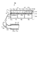
本発明の処理装置に係る実施の形態として、被処理体であるウエハWに処理流体である薬液を供給してウエハWに付着したパーティクルや汚染物質を除去する液処理を行う液処理装置2の構成について以下に図面を参照しながら説明する。本発明の液処理装置2は、外部から複数枚のウエハWを収納したキャリアCの搬入出が行われるキャリア載置ブロック2Aと、ウエハWの受け渡し部を備えた受け渡しブロック2Bと、ウエハWに対して所定の液処理を行う処理ブロック2Cと、を備えている。これらは、キャリア載置ブロック2Aを前方側として、キャリア載置ブロック2A、受け渡しブロック2B、処理ブロック2Cが前後方向(図1中X方向)に一列に配列され、互いに接続されている。
As an embodiment according to the processing apparatus of the present invention, a liquid processing apparatus 2 for supplying a chemical liquid as a processing fluid to a wafer W that is an object to be processed and performing a liquid processing for removing particles and contaminants attached to the wafer W. The configuration will be described below with reference to the drawings. The liquid processing apparatus 2 of the present invention includes a carrier mounting block 2A for carrying in / out a carrier C containing a plurality of wafers W from the outside, a
前記キャリア載置ブロック2Aは、例えば4個のキャリアCが載置されるキャリア載置部21を備えると共に、当該キャリア載置部21上に載置されたキャリアCと受け渡しブロック2Bとの間でのウエハWの受け渡しを行う搬入出アームA1を備えている。この搬入出アームA1は、ウエハを保持する保持アーム22が、例えば前後方向に進退自在、左右方向(図1中Y方向)に移動自在、回動自在及び昇降自在に構成されている。
The carrier placement block 2A includes, for example, a
前記受け渡しブロック2Bは、受け渡しステージ23を多段に備えており、この受け渡しステージ23に対しては、搬入出アームA1と、後述する処理ブロック2Cに設けられたプロセスアームA2とが夫々アクセスできるように構成されている。
The
前記処理ブロック2Cは、前後方向に伸びるウエハWの搬送路24を備えており、この搬送路24には、プロセスアームA2が設けられている。また、前記搬送路24を挟んで、キャリア載置ブロック2A側から見て左右に各々5台の処理部をなす液処理ユニット3(3A〜3J)が互いに対向するように列設されている。前記プロセスアームA2は、10台の液処理ユニット3及び既述の受け渡しステージ23に対してウエハWの受け渡しを行うものである。当該プロセスアームA2はウエハWの裏面側周縁を保持する保持アーム25が進退自在、回転自在、昇降自在、及び搬送路24に沿って移動自在に構成されている。
The processing block 2C includes a
次に図3を参照しながら前記液処理ユニット3の構成について説明する。液処理ユニット3は、ウエハWに対して枚葉処理を行う処理ユニットであり、ウエハWに対する液処理が実行される密閉された処理空間を形成するアウターチャンバ31と、アウターチャンバ31内にてウエハWをほぼ水平に保持した状態で回転させるウエハ保持機構32と、ウエハ保持機構32に保持されたウエハWの上面側に薬液を供給するノズルアーム33と、ウエハ保持機構32を取り囲むようにアウターチャンバ31内に設けられ、回転するウエハWから周囲に飛散した薬液を受けるためのインナーカップ34と、を備えている。
Next, the configuration of the liquid processing unit 3 will be described with reference to FIG. The liquid processing unit 3 is a processing unit that performs single wafer processing on the wafer W, and an
アウターチャンバ31は、互いに隣り合う他の液処理ユニット3とは区画された筐体内に設けられており、この筐体内には不図示のウエハ搬入口を介して対応するプロセスアームA2によりウエハWが搬入出される。このアウターチャンバ31の底面には、当該チャンバ31内の雰囲気を排気するための排気路35が接続されると共に、アウターチャンバ31の底面に溜まったDIWなどの排水を排出するための排水路36が設けられている。インナーカップ34は、ウエハ保持機構32の近傍の処理位置と、処理位置の下方側の退避位置との間で昇降自在に構成されている。図中37は、インナーカップ34に設けられた排液路である。また、ウエハ保持機構32の内部には薬液供給路38が形成されており、回転するウエハWの下面に当該薬液供給路38を介して薬液を供給することができるようになっている。
The
ノズルアーム33は、先端部に薬液供給用のノズルを備えている。このノズルには、IPA供給部41、DIW供給部42、SC1供給部43、DHF供給部44に供給路45、46、47を介して接続されている。また、DIW供給部42、SC1供給部43、DHF供給部44は、供給路47、48を介して、ウエハ保持機構32の供給路38に接続されている。
The
前記IPA供給部41は、高い揮発性を利用してウエハWを乾燥させるためのIPA(イソプロピルアルコール)を供給し、DIW供給部42は、薬液処理後のウエハWに残存する薬液を除去するためのリンス液であるDIW液(Delonized Water)を供給するものである。また、SC1供給部43は、ウエハW表面のパーティクルや有機性の汚染物質を除去する薬液であるSC1液(アンモニアと過酸化水素水の混合液)を供給し、DHF供給部44は、ウエハW表面の自然酸化膜を除去するDHF液(希フッ酸水溶液:DHF(Diluted HydroFluoric acid)液)を供給するものである。図中、41aは、マスフローコントローラ、40は切替え弁、49a、49bは、各々ノズルアーム33側、ウエハ保持機構32側への薬液供給量を調整するマスフローコントローラである。ここで、前記薬液の内、IPAが有機系薬液、DHF液が酸性薬液、SC1液がアルカリ性薬液に夫々相当する。
The
続いて前記液処理ユニット3の排気系について説明する。この例では搬送路24の両側に5個の液処理ユニット3が配列されているが、これら搬送路24の片側に配列された5個の液処理ユニット3の夫々の排気路35は、図2及び図4に示すように、夫々本発明の流路切替え装置をなす流路切替え部5を介して流路形成部材6に接続されている。従って、この例においては、キャリア載置ブロックA1側から見て、搬送路24の右側に配列された5個の液処理ユニット3A〜3Eは、共通の流路形成部材6に接続され、キャリア載置ブロックA1側から見て、搬送路24の左側に配列された5個の液処理ユニット3F〜3Jは、共通の流路形成部材(図示せず)に接続されている。前記液処理ユニット3の排気路35は、処理流体を排出する共通流路に相当する。以下、キャリア載置ブロックA1側から見て、搬送路24の右側に配列された5個の液処理ユニット3A〜3Eの排気系を例にして説明する。
Next, the exhaust system of the liquid processing unit 3 will be described. In this example, five liquid processing units 3 are arranged on both sides of the
前記流路形成部材6は、図4及び図5に示すように、互いに並行に伸びるように構成されると共に、前記複数種別の処理流体を含む気流を個別に通気させる複数の専用排出路(接続用流路)を形成するものである。この例では、流路形成部材6は、3種類の処理流体を含む気流を個別に排気するように、第1の流路61、第2の流路62、第3の流路63を備えており、これら第1〜第3の流路61〜63は壁部64により周囲が覆われている。例えば流路形成部材6は、3本の配管60(60A〜60C)を互いに水平に並べて形成される。但し、図5(a)では、図示の便宜上、隣接する流路61〜63を区画する壁部64aは、一方の配管60に属するもののみを描いており、図5(b)では、配管60の間の隙間は省略している。
As shown in FIGS. 4 and 5, the flow path forming member 6 is configured to extend in parallel with each other, and a plurality of dedicated discharge paths (connections) for individually aerating airflows including the plurality of types of processing fluids. For use). In this example, the flow path forming member 6 includes a
これら第1〜第3の流路61〜63の内、例えば第1の流路61は有機系薬液を含む気流、第2の流路62はアルカリ性薬液を含む気流、第3の流路63は酸性薬液を含む気流の専用排出路として夫々割り当てられている。この流路形成部材6の一端側には、前記第1〜第3の流路61〜63の夫々に専用排気ライン61a〜63aが接続されており、これら専用排気ライン61a〜63aは、工場用力の排気ラインを介して夫々排ガスの除害設備に接続されている。こうして、前記専用排気ライン61a〜63aにより流路形成部材6の各流路61〜63の夫々の内部は陰圧に設定されている。そして、各液処理ユニット3A〜3E内の雰囲気は排気路35を介して排気され、後述する流路切替え部5により、処理流体の種別に対応して切替え接続された流路61〜63を介して、夫々の専用排気ライン61a〜61cに排気されるように構成されている。
Among these first to
そして、この流路形成部材6の一面側の壁部64、例えば上壁部64bには、流路形成部材6の長さ方向(図4中X方向)と直交し、この直交方向において全ての流路61〜63を覆うように、液処理ユニット3A〜3E毎に外筒51(51A〜51E)が設けられている。この例では、外筒51は、図4、図6及び図7に示すように、例えば円筒形状に構成され、支持部材52を介して流路形成部材6に取り付けられている。ここで、図6は、外筒51と支持部材52とを下面側(流路形成部材6側)から見た概略斜視図であり、外筒51は一点鎖線で示している。
Further, the
流路形成部材6における外筒51が設けられた領域には、図5及び図7に示すように、第1〜第3の流路61〜63に対して夫々開口する第1〜第3の開口部60a〜60cが形成されている。一方、外筒51の周壁には、第1〜第3の流路61〜63に対して夫々開口する第1〜第3の接続口51a〜51cが、当該外筒51の長さ方向に沿って間隔をおいて形成されている。また、前記支持部材52にも、第1〜第3の流路61〜63に対して夫々開口する第1〜第3の接続口52a〜52cが夫々形成されている。こうして、外筒51と流路形成部材6の3個の流路61〜63は、開口部60a〜60c及び接続口51a〜51c,52a〜52cを介して互いに連通するように構成されている。ここで、前記流路形成部材6の開口部60a〜60cは、外筒51により覆われる大きさに設定されている。
As shown in FIGS. 5 and 7, in the region where the
前記外筒51の内部には、図6〜図8に示すように、前記外筒51内に回転自在に挿入された円筒形状の回転筒53が設けられている。この回転筒53の一端側は、略水平な回転軸54を介して、外筒51の一端側の外部に設けられた回転駆動部55に接続されている。この回転駆動部55は、例えばロータリーシリンダにより構成され、回転筒53は、外筒51の内部にて、略水平軸周りに回転自在に構成されることになる。
As shown in FIGS. 6 to 8, a cylindrical
一方、外筒51の他端側には、液処理ユニット3の排気路35が接続されており、回転筒53の他端側は、外筒51の他端側に接近した位置にて開口している。こうして、回転筒53の他端側は排気路35に接続される接続口として構成され、当該回転筒53の内部に、前記排気路35から排気された気流が通気するようになっている。図中56は、回転駆動部55を収納する収納部である。
On the other hand, the
図中57は、回転筒53の外部に部分的に設けられた例えばリング状の突部であり、この突部57と外筒51との間には僅かな隙間が形成されている。このような外筒51、回転筒53及び突部57は、例えばポリ塩化ビニル(PVC)、ポリプロピレン(PP)、ポリテトラフルオロエチレン(PTFE)等の材質により構成されている。ここで、回転筒53は一端側にて軸支されているので、長さ方向において僅かに傾くおそれもあるが、その場合は突部57が外筒51の内部に接触して、回転筒53を支持することになる。このような状態であっても、突部57は部分的に形成されていて幅が狭く、回転筒53は軽量であるので、回転筒53の回転は妨げられない。
In the figure,
また、回転筒53の周壁には、図6及び図7に示すように、当該回転筒53の長さ方向に沿って間隔をおいて、前記外筒51の複数の接続口51a〜51cに対応する位置に複数の開口部53a〜53cが形成されている。図7(b)は外筒51の展開図、図7(c)は回転筒53の展開図を示すものであるが、この例では、図7(b)、(c)に示すように、外筒51の第1〜第3の接続口51a〜51cは、外筒51の長さ方向に沿って一列に配列されている。一方、回転筒53の第1〜第3の開口部53a〜53cは、回転筒53の周方向の異なる位置に、前記外筒51の3個の接続口51a〜51cに夫々対応するように形成されている。この際、これら開口部53a〜53cは、夫々の周方向の中心位置が、回転筒53を周方向において3等分する位置になるように、互いに120°離れて形成されている。
Further, as shown in FIGS. 6 and 7, the peripheral wall of the
そして、回転筒53の前記他端側(排気路35側)には、外筒51の第1の接続口51aに対応する第1の開口部53a、前記一端側(回転駆動部55側)には、外筒51の第3の接続口51cに対応する第3の開口部53c、中央部には、外筒51の第2の接続口51bに対応する第2の開口部53bが夫々形成されている。
Then, on the other end side (
こうして、回転筒53を回転させたときに、ある位置では、前記第1の接続口51aと第1の開口部53aとが対向し、ある位置では、第2の接続口51bと第2の開口部53bとが対向し、ある位置では、第3の接続口51cと第3の開口部53cとが対向するように構成されている。
Thus, when the
これにより、前記回転筒53の第1〜第3の開口部53a〜53cは、当該回転筒53を回転する間に、互いに対応する外筒51の第1〜第3の接続口51a〜51cと回転筒53の第1〜第3の開口部53a〜53cとの組の一つが重なり合って連通し、かつ他の組については連通しない状態が各組の間で順番に起こるように配置されていることになる。
Thereby, the first to
この際、流路形成部材6の第1〜第3の開口部60a〜60cは、外筒51の第1〜第3の接続口51a〜51cと対応するように設けられており、前記開口部60a〜60cは、外筒51により覆われるように構成されている。従って、互いに対応する外筒51の第1〜第3の接続口51a〜51cと回転筒53の第1〜第3の開口部53a〜53cとの組の一つが重なり合って連通するときには、当該組に対応する流路形成部材6の開口部60a〜60cが開き、連通しない他の組については、これら他の組に対応する流路形成部材6の開口部60a〜60cが閉じられる。こうして、流路切替え部5によって、前記液処理ユニット3の排気路35が、前記処理流体の種別に対応した流路61〜63に切替え接続されることになる。
At this time, the first to
この例では、回転駆動部55は、後述する制御部100からの指令に基づき、予め設定された3つの位置で停止するように構成されており、例えば第1の位置では、第1の開口部53aと第1の接続口51aとが対向し、第2の位置では、第2の開口部53bと第2の接続口51bとが対向し、第3の位置では、第3の開口部53cと第3の接続口51cとが対向するようになっている。
In this example, the
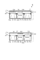
そして、前記第1の位置では、図8に示すように、第1の接続口51aが開かれ、第2及び第3の接続口51b,51cが閉じられて、液処理ユニット3からの有機系薬液を含む排気成分が第1の流路61に排気される。また、前記第2の位置では、図9(a)に示すように、第2の接続口51bが開かれ、第1及び第3の接続口51a,51cが閉じられて、液処理ユニット3からのアルカリ性薬液を含む排気成分が第2の流路62に排気される。さらに、第3の位置では、図9(b)に示すように、第3の接続口51cが開かれ、第1及び第2の接続口51a,51bが閉じられて、液処理ユニット3からの酸性薬液を含む排気成分が第3の流路63に排気される。
Then, in the first position, as shown in FIG. 8, the
こうして、外筒51、回転筒53及び回転駆動部55とにより、流路切替え部5が構成されている。この例では、例えば回転筒53が第3の位置(酸性薬液の排気成分を排気する位置)に位置にあるときを中間位置とし、ここから回転筒53を回転駆動部55側から見て時計回りに回転させることにより第1の位置に位置させ、また回転筒53を回転駆動部55側から見て反時計回りに回転させることにより第2の位置に位置させるように構成されている。
Thus, the flow
ここで、互いに対応する外筒51の接続口51a〜51cと回転筒53の開口部53a〜53cとの組の一つが重なり合って連通するとは、接続口51a〜51cと開口部53a〜53cとの間に連通する開口領域が形成されていればよく、外筒の接続口51a〜51cと回転筒の開口部53a〜53cとの互いの開口領域が完全に対向する場合のみならず、開口領域の一部同士が対向して連通する場合も含まれる。
Here, when one of the sets of the
ここで、外筒51と回転筒53の寸法の一例について示すと、外筒51は、長さが例えば520mm、内径が例えばφ100mmに設定される。また、回転筒53は、長さが例えば512mm、内径が例えばφ83mmに設定され、外筒51と回転筒53との間の隙間L1の幅は例えば0.5mmに設定されている。さらに、開口部53a〜53cの周方向の長さL2(図7(b)参照)は、例えば70mmに設定されている。
Here, as an example of the dimensions of the
さらに、流路形成部材6における第1〜第3の流路61〜63の他端側は開放されると共に、これら第1〜第3の流路61〜63の他端側には、夫々取り込み量調整バルブV11〜V13が設けられている。この取り込み量調整バルブV1〜V13は例えばバタフライバルブにより構成されており、例えば制御部100からの指令に基づき、流路形成部材6の上壁部64bに設けられた駆動機構をなすモータM11〜M13によりその開度が調整される。
Further, the other end sides of the first to
この取り込み量調整バルブV11〜V13は、夫々の流路61〜63において、液処理ユニット3の排気路35からの排気量に関わらず、一定量の気流を排気するために設けられている。このため、流路切替え部5A〜5Eによる流路形成部材6の第1〜第3の開口部60a〜60cの開閉状態に応じて、第1〜第3の流路61〜63毎に開度が決定される。つまり、第1〜第3の流路61〜63毎に開口部60a〜60cの開閉数に基づいて、所定の開度で取り込み用調整バルブV11〜V13を開き、所定量の大気を夫々の流路61〜63に導入するようになっている。こうして、各流路61〜63では、液処理ユニット3からの排気と大気との組み合わせによりトータルの排気量が一定量になるように制御されている。
The intake amount adjusting valves V11 to V13 are provided for exhausting a certain amount of airflow in each of the
具体的に図10を参照して説明すると、例えば全ての液処理ユニット3A〜3Eの流路切替え部5A〜5Eが第1の開口部60aを開き、第2及び第3の開口部60b、60cを閉じるように調整されているときには、取り込み量調整バルブV11は閉じ、取り込み量調整バルブV12,V13は第1の開度で開いた状態になり、第2及び第3の流路62,63では大気が取り込まれるように設定されている。
Specifically, referring to FIG. 10, for example, the flow
また、例えば第1の流路61を例にして説明すると、例えば全ての開口部60aが閉じているときは第1の開度、1個の開口部60aが開くときは第2の開度、2個の開口部60aが開くときは第3の開度、3個の開口部60aが開くときは第4の開度、4個の開口部60aが開くときは第5の開度で開くように設定されている。このとき、取り込み量調整バルブV11の開度は、第1の開度>第2の開度>第3の開度>第4の開度>第5の開度となる。このような開度の制御は、後述する制御部100からの指令に基づいて、モータM11により行われる。
Further, for example, the
こうして、流路形成部材6の第1〜第3の流路61〜63では、図10(b)に示すように、流路61〜63毎に液処理ユニット3からの排気量に基づいて、取り込み用調整バルブV11〜V13の開度が制御され、所定量の大気が取り込まれるようになっている。この例では、第1の流路61は1個の液処理ユニット3Eに対応する開口部60aのみが開かれているので、取り込み量調整バルブV11は第2の開度、第2及び第3の流路62、63は2個の液処理ユニット3A,3B(3C,3D)に対応する開口部60b(60c)が開かれているので、取り込み量調整バルブV12、V13は夫々第3の開度で開くように制御される。この例では、前記流路形成部材6の接続用流路61〜63の端部の開口が流体取り込み用開口部に相当する。
Thus, in the first to
また、第1〜第3の流路61〜63の出口側、例えば専用排気ライン61a〜63aとの接続部付近にて、流路61〜63毎に流量検出センサを用いて夫々の流路61〜63の排気量を検出し、この検出値に基づいて、トータルの排気量が所定量になるように、各取り込み量調整バルブV11〜V13の開度を調整して、大気の取り込み量を制御するようにしてもよい。
Further, on the outlet side of the first to
さらに、例えば各液処理ユニット3A〜3Eの排気路35の内部における流路切替え部5の上流側近傍には、夫々圧力損失調整バルブV2(V21〜V25)が設けられている。この圧力損失調整バルブV21〜V25は例えばバタフライバルブよりなり、駆動機構によりその開度が調整されるように構成されている。この例では、図4及び図6に示すように、駆動機構201〜205は、回転筒53の回転駆動部55の収納部56近傍に設けられており、2本の駆動軸58A,58Bを介して圧力損失調整バルブV21〜V25の回転軸59に動力が伝達されるように構成されている。
Further, for example, pressure loss adjusting valves V2 (V21 to V25) are provided in the vicinity of the upstream side of the flow
この圧力損失調整バルブV21〜V25は、5台の液処理ユニット3A〜3Eにおいて排気路35内の圧力損失を揃えるために設けられている。つまり、工場の用力の排気ラインに近い液処理ユニット3Eの排気路35は、前記排気ラインに遠い液処理ユニット3Aの排気路35よりも圧力損失が小さく、排気量が大きくなるからである。従って、排気ラインからの位置に応じて、圧力損失調整バルブV21〜V25の開度が調整され、その開度は、排気ラインに遠い排気路35程、開度が大きくなるように、例えば液処理ユニット3Aの圧力損失調整バルブV21>液処理ユニット3Bの圧力損失調整バルブV22>液処理ユニット3Cの圧力損失調整バルブV23>液処理ユニット3Dの圧力損失調整バルブV24>液処理ユニット3Eの圧力損失調整バルブV25になるように設定される。
The pressure loss adjusting valves V21 to V25 are provided to equalize the pressure loss in the
また、この液処理装置には制御部100が設けられている。この制御部100は例えばCPUと記憶部とを備えたコンピュータからなり、記憶部には当該液処理装置2の作用、例えば液処理ユニット3にウエハWを搬入して液処理を行った後、液処理後のウエハWをキャリアCに格納するまでの動作に係わる制御についてのステップ(命令)群が組まれたプログラムがレシピ毎に記録されている。前記プログラムは、例えばハードディスク、コンパクトディスク、マグネットオプティカルディスク、メモリーカード等の記憶媒体に格納され、そこからコンピュータにインストールされる。 In addition, the liquid processing apparatus is provided with a control unit 100. The control unit 100 includes, for example, a computer including a CPU and a storage unit. After the liquid processing apparatus 2 performs the liquid processing by loading the wafer W into the liquid processing unit 3, for example, the liquid processing unit 3, the liquid processing unit 2 A program in which a group of steps (commands) for control related to operations until the processed wafer W is stored in the carrier C is recorded for each recipe. The program is stored in a storage medium such as a hard disk, a compact disk, a magnetic optical disk, or a memory card, and is installed in the computer therefrom.
また、制御部100では、液処理ユニット3内にて実行されている処理の種類に応じて薬液供給系や排気系を図12に示す切替え先に切替えるように構成されている。各液処理ユニット3では、ウエハ搬入(P1)→アルカリ性薬液処理(P2)→リンス洗浄(P3)→振切乾燥(P4)→酸性薬液処理(P5)→リンス洗浄(P6)→IPA乾燥(P7)→ウエハの入れ替え(P8)の各動作が繰り返し行われており、これらの動作に対応して薬液供給系や排気系が切替えられる。 Further, the control unit 100 is configured to switch the chemical solution supply system and the exhaust system to the switching destination shown in FIG. 12 according to the type of processing executed in the liquid processing unit 3. In each liquid processing unit 3, wafer transfer (P1) → alkaline chemical processing (P2) → rinsing cleaning (P3) → shaking drying (P4) → acidic chemical processing (P5) → rinsing cleaning (P6) → IPA drying (P7) ) → Wafer replacement (P8) is repeated, and the chemical solution supply system and the exhaust system are switched in response to these operations.
即ち、薬液供給系については、アルカリ性薬液処理(P2)時にSC1液、リンス洗浄(P3,P6)時にDIW液、酸性薬液処理(P5)時にDHF液がウエハWの上面側、下面側の双方に供給され、また、IPA乾燥(P7)時にはウエハWの上面にIPAが供給されるように薬液供給系が切替えられる。 That is, with respect to the chemical solution supply system, the SC1 solution is applied to both the upper and lower surfaces of the wafer W during the alkaline chemical treatment (P2), the DIW solution during the rinse cleaning (P3, P6), and the DHF solution during the acidic chemical treatment (P5) The chemical supply system is switched so that IPA is supplied to the upper surface of the wafer W during IPA drying (P7).
また、排気系については、アルカリ性薬液処理(P2)〜振切乾燥(P4)までの期間中は、流路形成部材6の第2の流路62、酸性薬液処理(P5)〜リンス洗浄(P6)までの期間中は流路形成部材6の第3の流路63、IPA乾燥(P7)〜ウエハ入れ替え(P8)の期間中は流路形成部材6の第1の流路61に、夫々排気先を切替えるように、流路切替え部5が制御される。この際、流路切替え部5の切替えによって、取り込み用調整バルブV11〜V13の開度が制御される。これら薬液供給系や、排気系の切替えタイミングは、例えば液処理装置における薬液処理の処理レシピとして予め制御部100の記憶部内に記憶されている。
As for the exhaust system, during the period from alkaline chemical treatment (P2) to shake-off drying (P4), the
続いて本発明の液処理装置2の作用について説明する。外部からキャリア載置ブロック2Aに搬入されたキャリアC内のウエハWは、搬入出アームA1により受け渡しブロック2Bの受け渡しステージ23に受け渡される。そして、処理ブロック2Cでは、プロセスアームA2が受け渡しステージ23からウエハWを受け取って、所定の液処理ユニット3の一つに進入して、当該ウエハWをウエハ保持機構32に受け渡す。
Then, the effect | action of the liquid processing apparatus 2 of this invention is demonstrated. The wafer W in the carrier C carried into the carrier mounting block 2A from the outside is delivered to the
ここで、各々の液処理ユニット3にて行われる液処理の一例について説明する。この液処理では、ウエハWが図示しないウエハ保持機構32に載置されると、ノズルアーム33をウエハW中央側の上方位置まで移動させ、インナーカップ34を処理位置まで上昇させる。そして、流路切替え部5では、回転筒53を第2の位置に設定し、ウエハ保持機構32によりウエハWを回転させながら、ノズル及びウエハ保持機構32側の薬液供給路38によりウエハWの上下面両側にSC1液を供給する。これにより、ウエハWに薬液の液膜が形成されてアルカリ性薬液洗浄が行われる。
Here, an example of the liquid processing performed in each liquid processing unit 3 will be described. In this liquid processing, when the wafer W is placed on the wafer holding mechanism 32 (not shown), the
この際、アウターチャンバ31内には、ウエハWの回転により、アルカリ性薬液が飛散しており、当該チャンバ31内の雰囲気には、アルカリ性薬液のミストが含まれている。従って、アウターチャンバ31内の雰囲気を排気路35を介して排気すると、排気路35から流路切替え部5、流路形成部材6の第2の流路62を介してアルカリ性薬液のミストを含む気流が排出されていく。アルカリ性薬液洗浄が終了すると、インナーカップ34を退避位置に移動し、ノズル及びウエハ保持機構の薬液供給路38へDIW液を供給することによりウエハW表面のSC1液を除去するリンス洗浄が実行される。リンス洗浄を終えたら振切乾燥を実行する。
At this time, the alkaline chemical liquid is scattered in the
しかる後、再びインナーカップ34を処理位置まで上昇させ、ウエハWを回転させると共に、流路切替え部5では、回転筒53を第3の位置に切替え、ノズル及びウエハ保持機構32の薬液供給路38より、ウエハWの上下面にDHF液を供給する。これにより、これらの面にDHF液の液膜が形成され、酸性薬液洗浄が行われ、液処理ユニット3からは排気路35、流路形成部材6の第3の流路63を介して酸性薬液のミストを含む気流が排気されていく。そして、所定時間の経過後、インナーカップ34を退避位置に下降させ、薬液の供給系統をDIW液に切替えて再びリンス洗浄を行う。
Thereafter, the
続いて、インナーカップ34を処理位置まで上昇させ、ウエハWを回転させると共に、流路切替え部5では回転筒53を第1の位置に切替え、ウエハWの上面にIPAを供給する。こうして、IPAの揮発性を利用したIPA乾燥を実行し、これによりウエハW表面に残存するリンス後のDIW液が完全に除去される。この際、液処理ユニット3からは排気路35、流路形成部材6の第1の流路61を介して有機系薬液のミストを含む気流が排気されていく。しかる後、インナーカップ34を退避位置まで退避させ、不図示の搬入出口を開き、液処理ユニット3内にプロセスアームA2を進入させて処理後のウエハWを搬出し、このウエハWを受け渡しステージ23に受け渡す。
Subsequently, the
ここで、この液処理装置では、プロセスアームA2により、10個の液処理ユニット3にウエハWが順次搬送されて、所定の液処理が行われる。そして、既述のように、キャリアブロック2A側から見て搬送路24の右側に配列された5個の液処理ユニット3A〜3E内の雰囲気は、夫々排気路35、流路切替え部5A〜5Eを介して共通の流路形成部材6に排気されていく。同様にキャリアブロック2A側から見て搬送路24の左側に配列された5個の液処理ユニット3F〜3J内の雰囲気は、夫々排気路35、流路切替え部5を介して共通の流路形成部材6に排気されていく。
Here, in this liquid processing apparatus, the wafer W is sequentially transferred to the ten liquid processing units 3 by the process arm A2, and predetermined liquid processing is performed. As described above, the atmospheres in the five
この際、液処理ユニット3A〜3J毎に、制御部100からの指令に基づいて流路切替え部5では回転筒53の位置が選択され、薬液の種別に対応して第1〜第3の流路61〜63に流路が切替えられて、専用排気路61a〜63aを介して排気されていく。従って、流路形成部材6側から見ると、第1〜第3の流路61〜63毎に開口部60a〜60cの開閉が行われることになる。
At this time, for each of the
そして、バルブV11〜V13では、既述のように、制御部100の指令に基づいて、流路61〜63毎に、開口部60a〜60cの開口数に対応して、開度の調整が行われる。こうして、流路形成部材6の各流路61〜63では、既述のように、開口部60a〜60cの開閉状態に関わらず、液処理ユニット3からの排気と大気との組み合わせにより、トータルの排気量が揃えられる。
And in valve | bulb V11-V13, as above-mentioned, based on the instruction | command of the control part 100, opening degree adjustment is performed for every flow path 61-63 corresponding to the numerical aperture of the opening
このような実施の形態によれば、液処理ユニット3から処理流体の排気ガスを排出するための排気路35を、前記処理流体の種別に対応した専用排出路(接続用流路)61〜63に切替え接続するために液処理ユニット3毎に流路切替え部5を設け、流路切替え部5では、回転筒53を周方向に回転させることにより流路の切替えを行っている。従って、複数の流路61〜63への切替えを、回転筒53の回転駆動部55のみで行うことができるので、当該切替え作業を行うにあたって駆動機構数が少なくて済む。このため、駆動機構の調整作業に要する時間や手間を削減することができる上、設置スペースの削減を図ることができる。
According to such an embodiment, the
また、このような流路切替え部5を液処理ユニット3に設けた場合には、ウエハWに対して複数種別の処理流体を互いに異なるタイミングで供給して処理を行うにあたり、処理流体の種類が多くなったとしても、1つの回転筒53を回転させることによって、前記処理流体の種別に対応した専用排出路に切替え接続することができる。このため、駆動機構の個数が少なくて済むので、駆動機構の調整作業に要する時間や手間を削減することができる上、設置スペースの削減を図ることができる。
Further, when such a flow
また、流路形成部材6の各接続用流路61〜63内においては、流路61〜63毎に設けられた取り込み用調整バルブV11〜V13の開度を調整することにより、既述のように、液処理ユニット3からの排気の有無に関わらず、流路61〜63内において、排気量を揃えることができる。このため、排気量の変動が抑えられ、各液処理ユニットにおいて処理状態のバラつきの発生を抑制することができる。
Moreover, in each connection flow path 61-63 of the flow path formation member 6, by adjusting the opening degree of the intake adjustment valves V11-V13 provided for each of the flow paths 61-63, as described above. In addition, the exhaust amount can be made uniform in the
この際、接続用流路61〜63内において、大気を取り込み、排気量を揃える場合であっても、流路61〜63毎に一つの取り込み用調整バルブV11〜V13を設ければよい。このため、複数の液処理ユニット3を配列する場合であっても、取り込み用調整バルブの個数が増加することなく、従来に比べてトータルのバルブの個数や、駆動機構の個数が大幅に削減される。従って、構成部材や駆動機構の個数が少なく、調整作業の手間や時間が削減され、省スペース化を図ることができる。
At this time, even if the atmosphere is taken in the
さらに、各液処理ユニット3の排気路35には、圧力損失調整バルブV2が設けられている。このため、各液処理ユニット3は、長い排気路61〜63の異なる位置に接続されているので、この圧力損失調整バルブV2の開度の調整により、液処理ユニット3の排気路35の圧力損失が液処理ユニット3同士の間で均一になるように調整されている。このため、液処理ユニット3同士の間では、排気量が揃えられ、液処理の処理状態のバラつきの発生を抑制することができる。
Further, a pressure loss adjusting valve V2 is provided in the
以上において、本発明の流路切替え装置は、例えば図13(a)に外筒71の展開図、図13(b)に回転筒72の展開図を夫々示すように、外筒71に形成される複数例えば3個の接続口711〜713を、周方向に沿って間隔をおいて形成する一方、前記回転筒72に形成される複数例えば3個の開口部721〜723を、長さ方向に沿って一列に形成するものであってもよい。さらにまた、外筒に形成される接続口の個数、回転筒に形成される開口部の個数は複数個であればよく、2個でもよいし、4個以上であってもよい。
In the above, the flow path switching device of the present invention is formed in the
また、例えば図14に示すように、支持部材91により回転筒53を支持するように設けてもよい。図14(b)は、図14(a)のA−A断面図である。この場合、支持部材91は、外筒51の長さ方向に沿って設けられ、その上面は外筒51の内部に突出し、回転筒53の開口部53a〜53cの外側の領域を下方側から支持するように設けられている。図中92は、支持部材91に設けられた開口部である。このような構成によれば、支持部材91により回転筒53が支持されるので、外筒51内の回転筒53の位置が安定する。
Further, for example, as shown in FIG. 14, the
さらに、例えば図15に示すように、回転筒82の他端側820を閉じるように構成すると共に、例えば外筒81の長さ方向において回転筒82の開口部に対応する位置に排気路(共通流路)35を接続するようにしてもよい。この例では、前記排気路35は回転筒82の中央部に形成された開口部822に対応する位置に接続されている。この例では、排気路35から外筒81と回転筒82との隙間に気流が排気され、前記開口部822、他の開口部(その一つは図示せず)、823から回転筒82の内部に前記気流が供給される。この際、前記開口部822が回転してある位置にあるときには、前記排気路35と対向するため、当該開口部822が共通流路35に接続される接続口に相当する。なお、前記接続口に相当する開口部は、流路切替え用の開口部とは別個に、流路切替えを阻害しない位置に設けるようにしてもよい。図15中、811,812,813は外筒81に形成された接続口である。
Further, for example, as shown in FIG. 15, the
また、外筒の接続口と、回転筒の開口は、回転筒の回転位置により、専用排出路(接続用流路)の開口と連通せず、専用排出路の全ての開口部60a〜60cが閉じられるように構成してもよい。
Further, the connection port of the outer cylinder and the opening of the rotary cylinder do not communicate with the opening of the dedicated discharge path (connection channel) depending on the rotation position of the rotary cylinder, and all the
また、本発明の流路切替え装置及び流路切替え方法は、共通流路が接続用流路の上流側にある場合、共通流路が接続用流路の下流側にある場合のいずれの場合にも用いることができ、共通流路及び接続用流路は、気体の流路であっても液体の流路であってもよい。さらに、本発明の処理装置及び処理方法は、処理流体が液体である場合、気体である場合のいずれにも適用でき、液体を排出する場合、気体を排出する場合のいずれにも適用できる。さらに上述の実施の形態のように、処理流体が液体であって、処理流体が供給される雰囲気を排気する場合には、この処理流体が供給される雰囲気には、処理流体が供給された雰囲気と、この処理流体のミストとを含む気流が含まれる。 Further, the flow path switching device and the flow path switching method of the present invention can be used in any case where the common flow path is on the upstream side of the connection flow path and the common flow path is on the downstream side of the connection flow path. The common flow path and the connection flow path may be a gas flow path or a liquid flow path. Furthermore, the processing apparatus and the processing method of the present invention can be applied to both the case where the processing fluid is a liquid and the case where the processing fluid is a gas, and the case where the processing fluid is discharged and the case where the gas is discharged. Further, when the processing fluid is liquid and the atmosphere to which the processing fluid is supplied is exhausted as in the above-described embodiment, the atmosphere to which the processing fluid is supplied is included in the atmosphere to which the processing fluid is supplied. And an air flow including the mist of the processing fluid.
さらにまた、処理流体を使う処理は上述の液処理に限られるものではなく、例えばウエハWにHMDS(ヘキサメチルジシラザン)などの蒸気を供給してウエハWの表面を疎水化する処理装置にも適用することができる。 Furthermore, the processing using the processing fluid is not limited to the above-described liquid processing. For example, a processing apparatus that supplies the wafer W with vapor such as HMDS (hexamethyldisilazane) to make the surface of the wafer W hydrophobic. Can be applied.
3 液処理ユニット
35 排気路(共通流路)
5 流路切替え部
51 外筒
51a〜51c 接続口
53 回転筒
53a〜53c 開口部
55 回転駆動部
6 流路形成部材
61〜63 専用排出路(接続用流路)
60a〜60c 開口部
3
DESCRIPTION OF
60a-60c opening
Claims (10)
外筒と、
この外筒の周壁に当該外筒の長さ方向に沿って間隔をおいて開口し、前記複数の接続用流路に夫々接続される複数の接続口と、
前記共通流路に接続される接続口が設けられ、外筒内に回転自在に挿入された回転筒と、
この回転筒の周壁に当該回転筒の長さ方向に沿って間隔をおいて前記外筒の複数の接続口に対応する位置に夫々形成された複数の開口部と、
前記回転筒を回転させるための回転駆動部と、を備え、
前記外筒の軸方向を前後方向とすると、当該外筒の一端側から他端側を見て、前記複数の接続口のいずれもが左側に開口するか、または前記複数の接続口のいずれもが右側に開口し、
前記回転筒の複数の開口部は、当該回転筒を回転する間に、互いに対応する外筒の接続口と回転筒の開口部との組の一つが重なり合って連通し、かつ他の組については連通しない状態が各組の間で順番に起こるように配置されていることを特徴とする流路切替え装置。 In a flow path switching device for switching and connecting a plurality of connection flow paths for flowing independent fluids to a common flow path connected to the connection flow path,
An outer cylinder,
A plurality of connection ports that are opened at intervals along the length direction of the outer cylinder on the peripheral wall of the outer cylinder, and are connected to the plurality of connection flow paths, respectively.
A rotary cylinder provided with a connection port connected to the common flow path and rotatably inserted into the outer cylinder;
A plurality of openings respectively formed at positions corresponding to a plurality of connection ports of the outer cylinder at intervals along the length direction of the rotating cylinder on the peripheral wall of the rotating cylinder;
A rotation driving unit for rotating the rotating cylinder,
When the axial direction of the outer cylinder is the front-rear direction, all of the plurality of connection ports open to the left side when viewed from one end side to the other end side of the outer cylinder, or any of the plurality of connection ports Opens to the right,
The plurality of openings of the rotating cylinder communicate with each other by overlapping one of the pairs of the connection ports of the outer cylinder and the opening of the rotating cylinder while rotating the rotating cylinder. A flow path switching device, characterized in that a state in which communication does not occur is arranged in order between each set.
この処理部へ供給された複数種別の処理流体を排出するために、前記処理部に設けられた共通流路と、
前記複数種別の処理流体毎に設けられ、前記処理流体を排出するための複数の専用排出路と、
前記共通流路を、前記処理流体の種別に対応した専用排出路に切替え接続するための流路切替え装置と、を備え、
前記流路切替え装置は、請求項1又は2記載の流路切替え装置であることを特徴とする処理装置。 A processing unit that performs processing while supplying a plurality of types of processing fluids to the target object at different timings;
To discharge a plurality of types of processing fluids supplied to the processing unit, a common flow path provided in the processing unit,
A plurality of dedicated discharge paths provided for each of the plurality of types of processing fluids, for discharging the processing fluids;
A flow path switching device for switching and connecting the common flow path to a dedicated discharge path corresponding to the type of the processing fluid,
3. The processing apparatus according to claim 1, wherein the flow path switching apparatus is the flow path switching apparatus according to claim 1.
複数の流体取り込み用開口部に夫々設けられ、流体の取り込み量を調整するために、これら流体取り込み用開口部の開度を調整する複数の取り込み量調整バルブと、
前記専用排出路内を通流する処理流体の流量に基づいて、前記流体取り込み用バルブの開度を制御する制御部と、を備えたことを特徴とする請求項4記載の処理装置。 A plurality of fluid intake openings respectively provided in the plurality of dedicated discharge paths;
A plurality of intake amount adjusting valves that are provided in a plurality of fluid intake openings, and adjust the opening of these fluid intake openings in order to adjust the amount of fluid intake;
The processing apparatus according to claim 4, further comprising: a control unit that controls an opening degree of the fluid intake valve based on a flow rate of the processing fluid flowing through the dedicated discharge path.
外筒と、
この外筒の周壁に当該外筒の長さ方向に沿って間隔をおいて開口し、前記複数の接続用流路に夫々接続される複数の接続口と、
前記共通流路に接続される接続口が設けられ、外筒内に回転自在に挿入された回転筒と、
この回転筒の周壁に当該回転筒の長さ方向に沿って間隔をおいて前記外筒の複数の接続口に対応する位置に夫々形成された複数の開口部と、を備え、
前記外筒の軸方向を前後方向とすると、当該外筒の一端側から他端側を見て、前記複数の接続口のいずれもが左側に開口するか、または前記複数の接続口のいずれもが右側に開口した流路切替え装置を用い、
前記回転筒を回転する間に、互いに対応する外筒の接続口と回転筒の開口部との組の一つが重なり合って連通し、かつ他の組については連通しない状態を形成して流路の切替え接続を行うことを特徴とする流路切替え方法。 In a flow path switching method for switching and connecting a plurality of connection flow paths for flowing independent fluids to a common flow path connected to the connection flow path,
An outer cylinder,
A plurality of connection ports that are opened at intervals along the length direction of the outer cylinder on the peripheral wall of the outer cylinder, and are connected to the plurality of connection flow paths, respectively.
A rotary cylinder provided with a connection port connected to the common flow path and rotatably inserted into the outer cylinder;
A plurality of openings formed respectively at positions corresponding to the plurality of connection ports of the outer cylinder at intervals along the length direction of the rotating cylinder on the peripheral wall of the rotating cylinder ,
When the axial direction of the outer cylinder is the front-rear direction, all of the plurality of connection ports open to the left side when viewed from one end side to the other end side of the outer cylinder, or any of the plurality of connection ports Uses a channel switching device that opens to the right ,
While rotating the rotating cylinder, one of the pairs of the outer cylinder connection port and the opening of the rotating cylinder corresponding to each other overlap and communicate with each other, and the other group forms a state of not communicating with each other. A flow path switching method characterized by performing switching connection.
処理部において、被処理体に対して複数種別の処理流体を互いに異なるタイミングで供給しながら処理を行う工程と、
この処理部へ供給された複数種別の処理流体を共通流路から排出する工程と、
前記複数種別の処理流体毎に用意され、各々が独立した処理流体を流すための複数の専用排出路の内、対応する専用排出路から処理流体を排出する工程と、を含み、
請求項7の流路切替え方法を用いて、前記共通流路を専用排出路に切替え接続することを特徴とする処理方法。 ,
In the processing unit, performing a process while supplying a plurality of types of processing fluids to the object to be processed at different timings;
Discharging a plurality of types of processing fluids supplied to the processing unit from the common flow path;
A step of discharging the processing fluid from a corresponding dedicated discharge path among a plurality of dedicated discharge paths prepared for each of the plurality of types of processing fluids, each of which flows an independent processing fluid,
A processing method comprising switching and connecting the common flow path to a dedicated discharge path by using the flow path switching method according to claim 7.
前記複数の専用排出路に夫々複数の流体取り込み用開口部を設け、前記専用排出路内を通流する処理流体の流量に基づいて、前記流体取り込み用開口部の開度を制御することを特徴とする請求項8記載の処理方法。 A plurality of the common flow paths are connected to the plurality of dedicated discharge paths,
A plurality of fluid intake openings are provided in the plurality of dedicated discharge paths, respectively, and the opening degree of the fluid intake openings is controlled based on the flow rate of the processing fluid flowing through the dedicated discharge paths. The processing method according to claim 8.
前記コンピュータプログラムは、請求項8又は9に記載の処理方法を実施するためのステップ群が組み込まれていることを特徴とする記憶媒体。 In the processing unit, a storage medium for storing a computer program used in a processing apparatus that performs processing while supplying a plurality of types of processing fluids to the target object at different timings,
A storage medium in which the computer program incorporates a group of steps for carrying out the processing method according to claim 8 or 9.
Priority Applications (5)
| Application Number | Priority Date | Filing Date | Title |
|---|---|---|---|
| JP2010141921A JP5240245B2 (en) | 2010-06-22 | 2010-06-22 | Channel switching device, processing device, channel switching method and processing method, and storage medium |
| KR1020110040840A KR101417208B1 (en) | 2010-06-22 | 2011-04-29 | Flow passage switching apparatus, processing apparatus, flow passage switching method, processing method and storage medium |
| US13/161,275 US8840752B2 (en) | 2010-06-22 | 2011-06-15 | Flow passage switching apparatus, processing apparatus, flow passage switching method, processing method and storage medium |
| CN201110168465.4A CN102315142B (en) | 2010-06-22 | 2011-06-17 | Flow path switching apparatus, processing apparatus, flow path switching method, and processing method |
| TW100121818A TWI487049B (en) | 2010-06-22 | 2011-06-22 | Flow path switching apparatus, processing apparatus, flow path switching method and memory medium |
Applications Claiming Priority (1)
| Application Number | Priority Date | Filing Date | Title |
|---|---|---|---|
| JP2010141921A JP5240245B2 (en) | 2010-06-22 | 2010-06-22 | Channel switching device, processing device, channel switching method and processing method, and storage medium |
Publications (3)
| Publication Number | Publication Date |
|---|---|
| JP2012009511A JP2012009511A (en) | 2012-01-12 |
| JP2012009511A5 JP2012009511A5 (en) | 2012-04-26 |
| JP5240245B2 true JP5240245B2 (en) | 2013-07-17 |
Family
ID=45327600
Family Applications (1)
| Application Number | Title | Priority Date | Filing Date |
|---|---|---|---|
| JP2010141921A Active JP5240245B2 (en) | 2010-06-22 | 2010-06-22 | Channel switching device, processing device, channel switching method and processing method, and storage medium |
Country Status (5)
| Country | Link |
|---|---|
| US (1) | US8840752B2 (en) |
| JP (1) | JP5240245B2 (en) |
| KR (1) | KR101417208B1 (en) |
| CN (1) | CN102315142B (en) |
| TW (1) | TWI487049B (en) |
Families Citing this family (16)
| Publication number | Priority date | Publication date | Assignee | Title |
|---|---|---|---|---|
| JP5240245B2 (en) * | 2010-06-22 | 2013-07-17 | 東京エレクトロン株式会社 | Channel switching device, processing device, channel switching method and processing method, and storage medium |
| JP2013011289A (en) * | 2011-06-28 | 2013-01-17 | Tokyo Electron Ltd | Gate valve and substrate processing system using same |
| JP6003716B2 (en) * | 2012-04-17 | 2016-10-05 | 株式会社デンソー | Channel switching device |
| CN103453215B (en) * | 2012-05-31 | 2016-04-27 | 英属开曼群岛商精曜有限公司 | Valve assembly and valve |
| JP6219848B2 (en) * | 2012-12-28 | 2017-10-25 | 株式会社Screenホールディングス | Processing device, exhaust gas switching device, exhaust gas switching unit and switching valve box |
| US9698029B2 (en) * | 2014-02-19 | 2017-07-04 | Lam Research Ag | Method and apparatus for processing wafer-shaped articles |
| JP6482979B2 (en) * | 2015-07-29 | 2019-03-13 | 東京エレクトロン株式会社 | Liquid processing equipment |
| TWI629116B (en) * | 2016-06-28 | 2018-07-11 | 荏原製作所股份有限公司 | Cleaning apparatus, plating apparatus using the same, and cleaning method |
| US10875061B2 (en) | 2016-08-10 | 2020-12-29 | Pat Technology Systems Inc. | Fume extraction apparatus with movable extraction aperture |
| JP6990602B2 (en) * | 2018-02-27 | 2022-01-12 | 東京エレクトロン株式会社 | Board processing equipment, board processing method and computer-readable recording medium |
| JP7019184B2 (en) * | 2018-07-17 | 2022-02-15 | スピードファム株式会社 | Processing liquid switching device |
| JP7203545B2 (en) | 2018-09-21 | 2023-01-13 | 株式会社Screenホールディングス | Substrate processing equipment |
| JP6611893B2 (en) * | 2018-11-01 | 2019-11-27 | 東京エレクトロン株式会社 | Substrate liquid processing equipment |
| CN209540113U (en) * | 2019-01-05 | 2019-10-25 | 宁波大叶园林工业股份有限公司 | A kind of novel four-way water through structure |
| JP7370277B2 (en) | 2020-02-26 | 2023-10-27 | 株式会社Screenホールディングス | Substrate processing equipment |
| CN113494680B (en) * | 2020-04-07 | 2023-05-12 | 添可智能科技有限公司 | Channel switching device, liquid supply system, and channel switching method |
Family Cites Families (11)
| Publication number | Priority date | Publication date | Assignee | Title |
|---|---|---|---|---|
| DD206687A3 (en) * | 1981-07-28 | 1984-02-01 | Mikroelektronik Zt Forsch Tech | METHOD AND DEVICE FOR FUELING LP CVD PROCESSES IN A PIPE REACTOR |
| JPH1012523A (en) * | 1996-06-21 | 1998-01-16 | Dainippon Screen Mfg Co Ltd | Substrate treatment apparatus |
| JP3669897B2 (en) * | 1999-06-09 | 2005-07-13 | 東京エレクトロン株式会社 | Substrate processing apparatus and substrate processing method |
| JP3584185B2 (en) * | 1999-09-21 | 2004-11-04 | エア・ウォーター株式会社 | Refrigerator and rotary valve used therefor |
| CN2541112Y (en) | 2002-05-29 | 2003-03-26 | 苏州精机机械工业有限公司 | Rotary oil level gate |
| JP4767783B2 (en) * | 2006-07-26 | 2011-09-07 | 東京エレクトロン株式会社 | Liquid processing equipment |
| CN101680861B (en) * | 2007-05-15 | 2012-10-10 | 通用电气健康护理生物科学股份公司 | Flow distributing valve |
| US8298338B2 (en) * | 2007-12-26 | 2012-10-30 | Samsung Electronics Co., Ltd. | Chemical vapor deposition apparatus |
| JP4881345B2 (en) * | 2008-04-03 | 2012-02-22 | 東京エレクトロン株式会社 | Pressure control mechanism, substrate processing apparatus, substrate processing method, and storage medium |
| JP5012651B2 (en) * | 2008-05-14 | 2012-08-29 | 東京エレクトロン株式会社 | Coating device, coating method, coating, developing device and storage medium |
| JP5240245B2 (en) * | 2010-06-22 | 2013-07-17 | 東京エレクトロン株式会社 | Channel switching device, processing device, channel switching method and processing method, and storage medium |
-
2010
- 2010-06-22 JP JP2010141921A patent/JP5240245B2/en active Active
-
2011
- 2011-04-29 KR KR1020110040840A patent/KR101417208B1/en active IP Right Grant
- 2011-06-15 US US13/161,275 patent/US8840752B2/en active Active
- 2011-06-17 CN CN201110168465.4A patent/CN102315142B/en active Active
- 2011-06-22 TW TW100121818A patent/TWI487049B/en active
Also Published As
| Publication number | Publication date |
|---|---|
| US8840752B2 (en) | 2014-09-23 |
| TWI487049B (en) | 2015-06-01 |
| CN102315142B (en) | 2015-03-18 |
| KR20110139096A (en) | 2011-12-28 |
| KR101417208B1 (en) | 2014-07-08 |
| CN102315142A (en) | 2012-01-11 |
| TW201214601A (en) | 2012-04-01 |
| US20110308626A1 (en) | 2011-12-22 |
| JP2012009511A (en) | 2012-01-12 |
Similar Documents
| Publication | Publication Date | Title |
|---|---|---|
| JP5240245B2 (en) | Channel switching device, processing device, channel switching method and processing method, and storage medium | |
| KR101524334B1 (en) | Liquid processing apparatus, liquid processing method and recording medium having computer program for performing the same method | |
| CN105575850B (en) | Substrate liquid processing apparatus | |
| US10128132B2 (en) | Substrate liquid processing apparatus | |
| JP6392143B2 (en) | Substrate processing apparatus, substrate processing method, and storage medium storing program for executing substrate processing method | |
| JP2012009511A5 (en) | ||
| JP7113949B2 (en) | Substrate processing equipment | |
| JP2005051089A (en) | Substrate treatment apparatus and method therefor | |
| US10373849B2 (en) | Substrate processing apparatus | |
| JP2014197592A (en) | Substrate processor | |
| TW201717301A (en) | Liquid processing device | |
| JP6611893B2 (en) | Substrate liquid processing equipment | |
| JP6675955B2 (en) | Substrate processing equipment | |
| JP2023142452A (en) | Processing liquid cabinet exhaust control method and substrate processing device | |
| JP2023095548A (en) | Substrate processing apparatus and substrate processing method |
Legal Events
| Date | Code | Title | Description |
|---|---|---|---|
| A521 | Request for written amendment filed |
Free format text: JAPANESE INTERMEDIATE CODE: A523 Effective date: 20120309 |
|
| A621 | Written request for application examination |
Free format text: JAPANESE INTERMEDIATE CODE: A621 Effective date: 20120522 |
|
| A977 | Report on retrieval |
Free format text: JAPANESE INTERMEDIATE CODE: A971007 Effective date: 20120919 |
|
| A131 | Notification of reasons for refusal |
Free format text: JAPANESE INTERMEDIATE CODE: A131 Effective date: 20121002 |
|
| A521 | Request for written amendment filed |
Free format text: JAPANESE INTERMEDIATE CODE: A523 Effective date: 20121203 |
|
| TRDD | Decision of grant or rejection written | ||
| A01 | Written decision to grant a patent or to grant a registration (utility model) |
Free format text: JAPANESE INTERMEDIATE CODE: A01 Effective date: 20130305 |
|
| A61 | First payment of annual fees (during grant procedure) |
Free format text: JAPANESE INTERMEDIATE CODE: A61 Effective date: 20130318 |
|
| FPAY | Renewal fee payment (event date is renewal date of database) |
Free format text: PAYMENT UNTIL: 20160412 Year of fee payment: 3 |
|
| R150 | Certificate of patent or registration of utility model |
Free format text: JAPANESE INTERMEDIATE CODE: R150 Ref document number: 5240245 Country of ref document: JP Free format text: JAPANESE INTERMEDIATE CODE: R150 |
|
| R250 | Receipt of annual fees |
Free format text: JAPANESE INTERMEDIATE CODE: R250 |
|
| R250 | Receipt of annual fees |
Free format text: JAPANESE INTERMEDIATE CODE: R250 |
|
| R250 | Receipt of annual fees |
Free format text: JAPANESE INTERMEDIATE CODE: R250 |
|
| R250 | Receipt of annual fees |
Free format text: JAPANESE INTERMEDIATE CODE: R250 |
|
| R250 | Receipt of annual fees |
Free format text: JAPANESE INTERMEDIATE CODE: R250 |
|
| R250 | Receipt of annual fees |
Free format text: JAPANESE INTERMEDIATE CODE: R250 |
|
| R250 | Receipt of annual fees |
Free format text: JAPANESE INTERMEDIATE CODE: R250 |