JP5239727B2 - Torque converter - Google Patents
Torque converter Download PDFInfo
- Publication number
- JP5239727B2 JP5239727B2 JP2008268118A JP2008268118A JP5239727B2 JP 5239727 B2 JP5239727 B2 JP 5239727B2 JP 2008268118 A JP2008268118 A JP 2008268118A JP 2008268118 A JP2008268118 A JP 2008268118A JP 5239727 B2 JP5239727 B2 JP 5239727B2
- Authority
- JP
- Japan
- Prior art keywords
- working fluid
- pump impeller
- torque converter
- wing portion
- blade
- Prior art date
- Legal status (The legal status is an assumption and is not a legal conclusion. Google has not performed a legal analysis and makes no representation as to the accuracy of the status listed.)
- Active
Links
Images


Landscapes
- Control Of Fluid Gearings (AREA)
Description
本発明は、自動車に適用される流体式のトルクコンバータに関するものであり、とくに、ポンプインぺラ、タービンランナのブレードを構成する翼部背面での作動流体の剥離に起因した損失を回避しようとするものである。 The present invention relates to a fluid type torque converter applied to an automobile, and in particular, an attempt is made to avoid loss due to separation of a working fluid on a back surface of a blade part constituting a blade of a pump impeller and a turbine runner. To do.
流体式のトルクコンバータは、ポンプインペラを配設したケース本体の開放端に、入力軸に連結するフロントカバーを配置してその相互間に作動流体の充填空間を区画形成し、この充填空間内にポンプインペラに対向するブレードを備えたタービンランナと、該ポンプインペラ及びブレードとの相互間に位置するステータと組み入れた構成からなっており、ポンプインペラの回転によって生み出された作動流体の流れをブレードに伝達せしめて該タービンライナを回転させることにより出力軸を駆動するものであって、通常の運転では、タービンライナには、作動流体による力(慣性力)と、タービンライナ自体の回転による遠心力と、該タービンライナをポンプインペラへ向けて押圧する力が作用している。 In the fluid type torque converter, a front cover connected to an input shaft is disposed at an open end of a case body provided with a pump impeller, and a working fluid filling space is defined between the front covers. It consists of a turbine runner with blades facing the pump impeller and a stator located between the pump impeller and the blades, and the flow of working fluid generated by the rotation of the pump impeller to the blades. The output shaft is driven by transmitting and rotating the turbine liner. In normal operation, the turbine liner has a force (inertial force) due to the working fluid and a centrifugal force due to the rotation of the turbine liner itself. The force which presses this turbine liner toward a pump impeller is acting.
ここに、トルクコンバータは、油を作動流体(媒体)とするものであってその流れや、エネルギーを伝達する際の損失を考慮に入れてポンプインペラ、タービンランナの入出力トルクの設計が行われており、従来は、作動流体が流れる経路にコアリングを設置してその経路を絞ることにより損失の軽減を図るようにしていた。 Here, the torque converter uses oil as the working fluid (medium), and the input and output torques of the pump impeller and turbine runner are designed in consideration of the flow and loss in transmitting energy. Conventionally, a loss is reduced by installing a coring in a path through which a working fluid flows and narrowing the path.
ところで、この種のトルクコンバータにあっては、ポンプインペラあるいはブレードを構成する翼部の背面(とくに先端域)において作動流体の流れが剥離するのが避けられないことから、これが損失となってトルクコンバータの流体性能に影響を与えることがあり、また、トルクコンバータを構成する流体要素の小型化を図る場合にコアリングの設置が困難となることがあった。 By the way, in this type of torque converter, it is inevitable that the flow of the working fluid is separated on the back surface (especially in the tip region) of the wing part constituting the pump impeller or blade. The fluid performance of the converter may be affected, and the installation of the coring may be difficult when the fluid elements constituting the torque converter are to be reduced in size.
トルクコンバータにつき、ストール回転数を上げることよって、カップリングレンジにおける動力伝達損失を減少させ、自動車の加速性能、燃費性能をともに向上させることを試みた先行技術としては特許文献1が参照される。
本発明の課題は、翼部の背面における作動流体の流れが剥離するのを抑制しこの剥離に起因した流体性能の低下を回避するとともにコンパクト化にも容易に対応し得るトルクコンバータを提案するところにある。 An object of the present invention is to propose a torque converter that suppresses the separation of the flow of the working fluid on the back surface of the wing portion, avoids a decrease in fluid performance due to the separation, and can easily cope with downsizing. It is in.
本発明は、上記の課題を解決するためになされたものであって、その具体的手段としては、ポンプインペラ、ブレードの何れか一方もしくは両方の翼部につき、作動流体の流出側に、作動流体の流入側の翼部よりもその厚さを厚くする肥厚部を設け、前記肥厚部は、翼部の背面側の厚さを増すことによって形成され、作動流体の流入側の翼部の流線に沿った外表面を有することを特徴とする。 The present invention has been made in order to solve the above-described problem. As specific means, the working fluid is disposed on the outflow side of the working fluid with respect to either one or both of the blades of the pump impeller and the blade. A thickened portion that is thicker than the wing portion on the inflow side is formed by increasing the thickness on the back side of the wing portion, and the streamline of the wing portion on the inflow side of the working fluid Characterized by having an outer surface along.
作動流体の流出側に位置する翼部に、流入側の翼部の厚さよりも厚い厚さを有する肥厚部を設けることにより作動流体が流れる際に生じていた剥離が抑えられ環状経路内を流れる作動流体の流量が増すとともに、翼部相互間の間隔が狭くなる(絞られる)ために流速が速くなり流体容量が増大することになる。 By providing a thickened portion having a thickness larger than the thickness of the wing portion on the inflow side on the wing portion located on the outflow side of the working fluid, the separation that occurred when the working fluid flows is suppressed, and the wing portion flows in the annular path. As the flow rate of the working fluid increases, the gap between the wings becomes narrow (squeezed), so that the flow rate increases and the fluid capacity increases.
また、トルクコンバータ内でポンプインペラからタービンランナにエネルギーを伝達する場合の損失(損失の設計)は、下記式(1)
T1ω1−T2ω2=L ‥‥(1)
T1:入力トルク(ポンプインペラトルク)
ω1:ポンプインペラ回転数
T2:出力トルク(タービンランナトルク)
ω2:タービンランナ回転数
L :損失
で求めるようにしており(ステータは回転していないのでエネルギーの発生は0である)、損失Lを軽減するためには従来、コアリングを設置することにより作動流体が流れる経路を絞る手法が採られていたが、本発明では肥厚部により翼部相互間に形成される隙間を適宜設定することにより損失の設計を行うことができるため、コアリングの設置を省略することができ、トルクコンバータの流体要素の小型化、ひいてはトルクコンバータそのもののコンパクト化が可能となる。
The loss (loss design) when energy is transferred from the pump impeller to the turbine runner in the torque converter is expressed by the following equation (1).
T 1 ω 1 −T 2 ω 2 = L (1)
T 1 : Input torque (pump impeller torque)
ω 1 : Pump impeller rotation speed T 2 : Output torque (turbine runner torque)
ω 2 : Turbine runner rotation speed L: Calculated by loss (energy generation is 0 because the stator is not rotating). To reduce the loss L, conventionally, a coring is installed. Although the technique of restricting the path through which the working fluid flows was taken, in the present invention, the loss can be designed by appropriately setting the gap formed between the wings by the thickened part. Thus, it is possible to reduce the size of the fluid element of the torque converter, and thus the torque converter itself.
以下、図面を用いて本発明をより具体的に説明する。
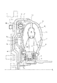
図1は、本発明にしたがうトルクコンバータの実施の形態を模式的に示した図であり、図における符号1はケース本体である。このケース本体1は開口端1′を形成する周壁1aと、この周壁1aに一体的につながりその内側にポンプインペラPの設置領域を形成する側壁1b(湾曲面からなる。)とからなっている。
Hereinafter, the present invention will be described more specifically with reference to the drawings.
FIG. 1 is a diagram schematically showing an embodiment of a torque converter according to the present invention, and
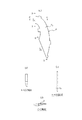
ポンプインペラPは側壁1aの回転軸Lの周りに複数の翼部P1を間隔をおいて配列することにより構成され、翼部の一つのみを取出して図2(a)〜(d)に示すように、作動流体の流出側i1に位置する翼部の先端域には、作動流体の流入側i2の翼部の厚さt2よりも厚くした厚さt1になる肥厚部eが設けられている。 Pump impeller P is constructed by arranging at intervals a plurality of wings P 1 about the axis of rotation L of the side walls 1a, taken out only one of the blade portion in FIG. 2 (a) ~ (d) As shown, a thickened portion e having a thickness t 1 greater than the thickness t 2 of the wing portion on the inflow side i 2 of the working fluid is provided at the tip region of the wing portion located on the outflow side i 1 of the working fluid. Is provided.
また、図1における符号2はケース本体1の開口端1′に合わさる周壁を備え、その内側に作動流体の充填空間Mを区画形成するフロントカバーである。このフロントカバー2はエンジンの回転軸に連結し、ケース本体1とともに回転可能に支持されており、このケース本体1とフロントカバー2によってポンプを構成している。
Further,
3はフロントカバー2の内壁面に沿い間隔をおいて回転可能に配置されたタービンランナである。このタービンランナ3は、タービンシェル3aと、タービンブレード3bから構成されていて、タービンシェル3aは、タービンブレード3bをポンプインペラPに対面するように固定保持している。
4はポンプインペラP及びブレード3bとの相互間に位置し、充填空間M内の作動流体をタービンライナ側からケース本体側(ポンプインペラ側)に向けて誘導するとともにポンプインペラP、ブレード3bと協働して充填空間M内に作動流体の環状経路を形成するステータ、5は回転方向を一方向のみに設定するワンウエイクラッチである。ワンウエイクラッチ5は入力側のハブh、出力側のハブh1との間でスラスト軸受けを介して位置決めされている。
4 is located between the pump impeller P and the
ステータ4は、ポンプ側とタービン側の回転速度差が大きい時には作動流体の流れをポンプ側の回転を助ける向きに変換(トルクの増幅)し、ワンウエイクラッチ5はポンプ側とタービン側の回転速度差が小さくなった時にステータ4を空転させる機能を有している。
The stator 4 converts the flow of the working fluid into a direction that assists rotation on the pump side when the difference in rotational speed between the pump side and the turbine side is large (amplification of torque), and the one-
また、6はタービンランナ3とフロントカバー2の相互間に配置されたロックアップクラッチである。このロックアップクラッチ6は変速の必要がない領域で入力軸と出力軸を直結する機能を有するものであり、ハブh1 に摺動自在に保持され、フロントカバー2の内壁面に対して接触、離隔する向きへの移動を可能とするロックアップピストン6aと、一端がロックアップピストン6aの外縁部に連係し、他端がタービンシェル3aの内周側の下端 にリベット等を介して固定保持されたトーションダンパー6b(主要構成部材)にて構成されている。
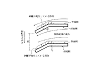
上記の構成になるトルクコンバータは、充填空間M内に、ポンプインペラ1b、タービンランナ3及びステータ4にて作動流体を循環させる環状経路が形成されており、エンジンの回転によりフロントカバー2が回転すると、これに連結するケース本体1も同時に回転しポンプインペラ1bによって作動流体に図3に示すような流れが生じ、この作動流体の流れがブレード3bへと伝達されてタービンライナ3が回転して変速機の入力軸につながる出力軸を駆動することになり、車輌の速度が所定の値に達する等の条件を満たすと、油圧装置(図示せず。)によりシェル3aとロックアップピストン6aとの間に作動油が供給され、その圧力によりロックアップピストン6aがフロントカバー2に向けて押圧されて摩擦部材が該フロントカバー2の内壁に接触することとなり、これによりポンプとタービンラナ3が直結状態に保持される。
In the torque converter configured as described above, an annular path for circulating the working fluid is formed in the filling space M by the pump impeller 1b, the
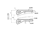
従来のトルクコンバータは、ポンプインペラPあるいはブレード3bを構成する翼部の流出側の端部が隣接する他の翼部の背面へ向けて湾曲又は屈曲させた図4に示すような形状を呈しており、翼部背面での作動流体の流れが剥離するのが避けられない状況にあったが、本発明のトルクコンバータは図5に示すように、作動流体の流出側i1の翼部P1の厚さt1が作動流体の流入側i2の翼部の厚さt2よりも厚くした肥厚部eが設けられているため作動流体は翼部P1の背面に沿って流れることから剥離は起こりにくくなり作動流体の流量が増すことなる。
The conventional torque converter has a shape as shown in FIG. 4 in which the end on the outflow side of the wing part constituting the pump impeller P or the
肥厚部eは、翼部の背面側の厚さを増すことによって形成することができるが、翼部の先端そのものを背面側に折り返すことにより形成してもよい。 The thickened portion e can be formed by increasing the thickness on the back side of the wing portion, but may be formed by folding the tip of the wing portion back to the back side.
翼部P1の流出側の厚さt1は流出側の厚さt2以上であればよい(t1>t2)。とくに翼部P1の先端そのものを背面側に折り返すことにより肥厚部eを形成する場合には、肥厚部eの厚さ方向における断面中心を元の厚さ方向における断面中心から1/2以上オフセットしたところに存在させるのが有効であり、これにより作動流体の剥離の抑制が期待できる。 The thickness t 1 on the outflow side of the wing portion P 1 may be equal to or greater than the thickness t 2 on the outflow side (t 1 > t 2 ). Particularly in the case of forming a thickened portion e by folding the tip itself of the blade portion P 1 on the back side, more than half the offset sectional center in the thickness direction of the thickened portion e from the cross-sectional center of the original thickness direction In this case, it is effective to prevent the working fluid from peeling off.
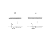
翼部P1の先端そのものを背面側に折り返すに際しては、該肥厚部eが作動流体の流れを妨げないようにすること、すなわち、作動流体の流入側の翼部の流線に沿った外表面をもたせることが肝要であり、そのためには、図6(a)(b)に示すように折り返すべき先端部位に予めコイニングにより先細り加工を施したり、プレスにより段差部を形成しておき、図7(a)(b)に示すような形状に仕上げる。 Upon folding of the tip itself wings P 1 on the rear side, that該肥thickness portion e does not interfere with the flow of the working fluid, i.e., the outer surface along the streamlines of the blade portion of the inflow side of working fluid In order to achieve this, as shown in FIGS. 6 (a) and 6 (b), the tip portion to be folded is preliminarily tapered by coining, or a step is formed by pressing. (A) Finish the shape as shown in (b).
なお、翼部P1をプレス加工によって成型する場合にはその加工に際して作動流体の流出側となる部位に所定の厚さになる肥厚部eを設ければよく、また、ポンプインペラPを鋳造によりケース本体1と一体に形成する場合には、作動流体の流出側となる部位に所定の厚さになる肥厚部eを形成すればよい。
Incidentally, may be provided thickened portions e that a predetermined thickness of the portion to be the outlet side of the working fluid during the process when molding the wings P 1 by press working, and by casting the pump impeller P When formed integrally with the case
肥厚部eはポンプインペラPを構成する翼部P1に設ける場合について説明したが、タービンブレード3bに設けてもよいしその両方に設けることができる。
Thickenings e has been described the case of providing the blade portion P 1 which constitutes the pump impeller P, may be provided on the
隣接する翼部の背面に近づくように先端域(先端を含む)を湾曲、もしくは屈曲した上掲図4に示したような形状を有する翼部を備えたものにおいて、肥厚部eを設けると、作動流体の剥離が抑制され流量が増加するだけでなく、翼部の相互における間隔wがその流出端において絞られて間隔がw1となる結果、作動流体の流通経路を絞るためのコアリングの設置が不要となる(コアリングを配置して流通経路を絞っていた部分は図5のa領域に相当する。)。肥厚部eによって翼部の相互における間隔wを絞ることにより流速は速くなり(流体性の適正化を図ることができる)トルクコンバータのコンパクト化を図っても所望のトルク容量を容易に確保し得る。 When the thickened portion e is provided with a wing portion having a shape as shown in FIG. 4 in which the tip region (including the tip) is curved or bent so as to approach the back surface of the adjacent wing portion, The separation of the working fluid is suppressed and the flow rate is increased, and the interval w between the wings is narrowed at the outflow end thereof so that the interval becomes w 1 . Installation is not necessary (the portion where the coring is arranged to narrow the distribution route corresponds to the region a in FIG. 5). By narrowing the interval w between the wing parts by the thickened part e, the flow velocity becomes faster (the fluidity can be optimized), and the desired torque capacity can be easily secured even if the torque converter is made compact. .
図8は、ポンプインペラを構成する翼部の流出側の先端域に肥厚部eを設けた本発明にしたがうトルクコンバータ(図4参照、適合例)と、従来構造のトルクコンバータ(図3参照、比較例)における容量係数τと速度比(速度比をトルクコンバータの流体容量(トルク容量)の代表値とする)との関係を示したグラフである。 FIG. 8 shows a torque converter according to the present invention in which a thickened portion e is provided at the tip end region on the outflow side of the wing portion constituting the pump impeller (see FIG. 4, a conforming example), and a conventional torque converter (see FIG. 3). 6 is a graph showing a relationship between a capacity coefficient τ and a speed ratio (a speed ratio is a representative value of a fluid capacity (torque capacity) of a torque converter) in a comparative example.
本発明にしたがうトルクコンバータにおいては、作動流体の翼部背面の表面近傍域における流れの剥離が抑制される結果、それによる損失を30%程度抑えることが可能で、流体容量(トルク容量)を速度比0.8で約20%程度向上させることができる。 In the torque converter according to the present invention, the flow separation in the vicinity of the surface of the back surface of the wing portion of the working fluid is suppressed, so that it is possible to reduce the loss by about 30%, and the fluid capacity (torque capacity) is increased in speed. A ratio of about 20% can be improved at a ratio of 0.8.
作動流体の流出側に位置する翼部の先端域に肥厚部を設けることで翼部背面での作動流体の剥離が抑制されるため、その剥離に起因した損失が軽減されたトルクコンバータが提供できる。 Since the separation of the working fluid on the back surface of the wing part is suppressed by providing the thickened part at the tip region of the wing part located on the outflow side of the working fluid, a torque converter with reduced loss due to the separation can be provided. .
1 ケース本体
1′ 開口端
1a 周壁
1b 側壁
2 フロントカバー
3 タービンランナ
3a タービンシェル
3b タービンブレード
4 ステータ
5 ワンウエイクラッチ
6 ロックアップクラッチ
6a ロックアップピストン
6b トーションダンパー
P ポンプインペラ
P1 翼部
i1 流出側
i2 流入側
e 肥厚部
M 充填空間
h ハブ
h1 ハブ
DESCRIPTION OF
Claims (1)
前記ポンプインペラ及びブレードの少なくとも一方の翼部のうちの作動流体の流出側に位置する翼部の先端域に、作動流体の流入側の翼部の厚さよりも厚くした肥厚部を設け、
前記肥厚部は、翼部の背面側の厚さを増すことによって形成され、作動流体の流入側の翼部の流線に沿った外表面を有することを特徴とするトルクコンバータ。 A case main body having pump impellers arranged at intervals along the inner wall, a front cover that fits the opening end of the case main body and defines a working fluid filling space therein, and faces the pump impeller of the case main body A turbine runner having blades and disposed at a distance along the inner wall surface of the front cover, and the pump impeller and the blades, and the working fluid in the filling space is transferred from the turbine runner side to the case body side. A torque converter that includes a stator that guides toward the air and that forms a return flow path of the working fluid in the filling space in cooperation with the pump impeller and the blade,
A thickened portion that is thicker than the thickness of the wing portion on the inflow side of the working fluid is provided in the tip region of the wing portion located on the outflow side of the working fluid of at least one wing portion of the pump impeller and the blade ,
The thickened portion is formed by increasing the thickness of the back surface side of the wing portion, and has an outer surface along the streamline of the wing portion on the inflow side of the working fluid .
Priority Applications (1)
| Application Number | Priority Date | Filing Date | Title |
|---|---|---|---|
| JP2008268118A JP5239727B2 (en) | 2008-10-17 | 2008-10-17 | Torque converter |
Applications Claiming Priority (1)
| Application Number | Priority Date | Filing Date | Title |
|---|---|---|---|
| JP2008268118A JP5239727B2 (en) | 2008-10-17 | 2008-10-17 | Torque converter |
Publications (2)
| Publication Number | Publication Date |
|---|---|
| JP2010096286A JP2010096286A (en) | 2010-04-30 |
| JP5239727B2 true JP5239727B2 (en) | 2013-07-17 |
Family
ID=42258112
Family Applications (1)
| Application Number | Title | Priority Date | Filing Date |
|---|---|---|---|
| JP2008268118A Active JP5239727B2 (en) | 2008-10-17 | 2008-10-17 | Torque converter |
Country Status (1)
| Country | Link |
|---|---|
| JP (1) | JP5239727B2 (en) |
Family Cites Families (7)
| Publication number | Priority date | Publication date | Assignee | Title |
|---|---|---|---|---|
| US3572034A (en) * | 1969-11-21 | 1971-03-23 | Ford Motor Co | Fabricated two-piece stator assembly for hydrokinetic torque converters |
| JPS52105679U (en) * | 1976-02-06 | 1977-08-11 | ||
| JPS5321363A (en) * | 1976-08-11 | 1978-02-27 | Daikin Mfg Co Ltd | Blade for torque converter |
| JPS5527502A (en) * | 1978-08-12 | 1980-02-27 | Nissan Motor Co Ltd | Fluid power transmission apparatus |
| JPS5697662A (en) * | 1979-12-28 | 1981-08-06 | Daikin Mfg Co Ltd | Stator for torque converter |
| JPS63152058U (en) * | 1987-03-25 | 1988-10-05 | ||
| JPH0259346U (en) * | 1988-10-25 | 1990-04-27 |
-
2008
- 2008-10-17 JP JP2008268118A patent/JP5239727B2/en active Active
Also Published As
| Publication number | Publication date |
|---|---|
| JP2010096286A (en) | 2010-04-30 |
Similar Documents
| Publication | Publication Date | Title |
|---|---|---|
| JP2594388B2 (en) | Torque converter | |
| JP5950212B2 (en) | Stator structure of torque converter and method of manufacturing stator of torque converter | |
| JP3884119B2 (en) | Torque converter impeller shell | |
| JP5239727B2 (en) | Torque converter | |
| WO2014045770A1 (en) | Stator structure for torque converter | |
| JPH10169751A (en) | Torque converter for vehicle | |
| JP2008008358A (en) | Hydraulic power transmission with lock-up clutch | |
| JPH01150031A (en) | Fluid type retarder | |
| US20050247054A1 (en) | Torque converter stator | |
| US5966934A (en) | Torque converter for motor vehicle | |
| JP4109895B2 (en) | Fluid coupling with baffle plate | |
| WO2005024263A1 (en) | Fluid coupling | |
| CN100406778C (en) | Hydraulic coupler | |
| JP2635359B2 (en) | Structure of torque converter | |
| JP5688005B2 (en) | Torque converter | |
| JP3555154B2 (en) | Fluid transmission with lock-up clutch | |
| JP2006038042A (en) | Torque converter | |
| JP3986412B2 (en) | Fluid torque transmission device | |
| JP2010127433A (en) | Torque converter | |
| JP4824421B2 (en) | Torque converter | |
| KR100823711B1 (en) | Torque converter for vehicle | |
| KR100839643B1 (en) | Torque converter for vehicle | |
| JPH06288460A (en) | Stator for torque converter | |
| JP3246524B2 (en) | Torque converter | |
| CN115773345A (en) | Torque converter and method for manufacturing reactor provided in torque converter |
Legal Events
| Date | Code | Title | Description |
|---|---|---|---|
| A621 | Written request for application examination |
Free format text: JAPANESE INTERMEDIATE CODE: A621 Effective date: 20110928 |
|
| RD03 | Notification of appointment of power of attorney |
Free format text: JAPANESE INTERMEDIATE CODE: A7423 Effective date: 20111125 |
|
| RD04 | Notification of resignation of power of attorney |
Free format text: JAPANESE INTERMEDIATE CODE: A7424 Effective date: 20120323 |
|
| A977 | Report on retrieval |
Free format text: JAPANESE INTERMEDIATE CODE: A971007 Effective date: 20120815 |
|
| A131 | Notification of reasons for refusal |
Free format text: JAPANESE INTERMEDIATE CODE: A131 Effective date: 20120821 |
|
| A521 | Written amendment |
Free format text: JAPANESE INTERMEDIATE CODE: A523 Effective date: 20121004 |
|
| RD04 | Notification of resignation of power of attorney |
Free format text: JAPANESE INTERMEDIATE CODE: A7424 Effective date: 20130213 |
|
| TRDD | Decision of grant or rejection written | ||
| A01 | Written decision to grant a patent or to grant a registration (utility model) |
Free format text: JAPANESE INTERMEDIATE CODE: A01 Effective date: 20130305 |
|
| A61 | First payment of annual fees (during grant procedure) |
Free format text: JAPANESE INTERMEDIATE CODE: A61 Effective date: 20130318 |
|
| FPAY | Renewal fee payment (event date is renewal date of database) |
Free format text: PAYMENT UNTIL: 20160412 Year of fee payment: 3 |
|
| R150 | Certificate of patent or registration of utility model |
Free format text: JAPANESE INTERMEDIATE CODE: R150 Ref document number: 5239727 Country of ref document: JP Free format text: JAPANESE INTERMEDIATE CODE: R150 |