JP5236040B2 - Encoding device, decoding device, encoding method, and decoding method - Google Patents
Encoding device, decoding device, encoding method, and decoding method Download PDFInfo
- Publication number
- JP5236040B2 JP5236040B2 JP2011089954A JP2011089954A JP5236040B2 JP 5236040 B2 JP5236040 B2 JP 5236040B2 JP 2011089954 A JP2011089954 A JP 2011089954A JP 2011089954 A JP2011089954 A JP 2011089954A JP 5236040 B2 JP5236040 B2 JP 5236040B2
- Authority
- JP
- Japan
- Prior art keywords
- layer
- encoding
- gain
- vector
- signal
- Prior art date
- Legal status (The legal status is an assumption and is not a legal conclusion. Google has not performed a legal analysis and makes no representation as to the accuracy of the status listed.)
- Active
Links
Images


Classifications
-
- G—PHYSICS
- G10—MUSICAL INSTRUMENTS; ACOUSTICS
- G10L—SPEECH ANALYSIS OR SYNTHESIS; SPEECH RECOGNITION; SPEECH OR VOICE PROCESSING; SPEECH OR AUDIO CODING OR DECODING
- G10L19/00—Speech or audio signals analysis-synthesis techniques for redundancy reduction, e.g. in vocoders; Coding or decoding of speech or audio signals, using source filter models or psychoacoustic analysis
- G10L19/005—Correction of errors induced by the transmission channel, if related to the coding algorithm
-
- G—PHYSICS
- G10—MUSICAL INSTRUMENTS; ACOUSTICS
- G10L—SPEECH ANALYSIS OR SYNTHESIS; SPEECH RECOGNITION; SPEECH OR VOICE PROCESSING; SPEECH OR AUDIO CODING OR DECODING
- G10L19/00—Speech or audio signals analysis-synthesis techniques for redundancy reduction, e.g. in vocoders; Coding or decoding of speech or audio signals, using source filter models or psychoacoustic analysis
- G10L19/02—Speech or audio signals analysis-synthesis techniques for redundancy reduction, e.g. in vocoders; Coding or decoding of speech or audio signals, using source filter models or psychoacoustic analysis using spectral analysis, e.g. transform vocoders or subband vocoders
- G10L19/032—Quantisation or dequantisation of spectral components
- G10L19/038—Vector quantisation, e.g. TwinVQ audio
-
- G—PHYSICS
- G10—MUSICAL INSTRUMENTS; ACOUSTICS
- G10L—SPEECH ANALYSIS OR SYNTHESIS; SPEECH RECOGNITION; SPEECH OR VOICE PROCESSING; SPEECH OR AUDIO CODING OR DECODING
- G10L19/00—Speech or audio signals analysis-synthesis techniques for redundancy reduction, e.g. in vocoders; Coding or decoding of speech or audio signals, using source filter models or psychoacoustic analysis
- G10L19/04—Speech or audio signals analysis-synthesis techniques for redundancy reduction, e.g. in vocoders; Coding or decoding of speech or audio signals, using source filter models or psychoacoustic analysis using predictive techniques
- G10L19/16—Vocoder architecture
- G10L19/18—Vocoders using multiple modes
- G10L19/24—Variable rate codecs, e.g. for generating different qualities using a scalable representation such as hierarchical encoding or layered encoding
-
- G—PHYSICS
- G10—MUSICAL INSTRUMENTS; ACOUSTICS
- G10L—SPEECH ANALYSIS OR SYNTHESIS; SPEECH RECOGNITION; SPEECH OR VOICE PROCESSING; SPEECH OR AUDIO CODING OR DECODING
- G10L25/00—Speech or voice analysis techniques not restricted to a single one of groups G10L15/00 - G10L21/00
- G10L25/03—Speech or voice analysis techniques not restricted to a single one of groups G10L15/00 - G10L21/00 characterised by the type of extracted parameters
- G10L25/18—Speech or voice analysis techniques not restricted to a single one of groups G10L15/00 - G10L21/00 characterised by the type of extracted parameters the extracted parameters being spectral information of each sub-band
Abstract
Description
本発明は、音声信号等の入力信号を符号化して伝送する通信システムに用いられる符号化装置、復号装置、符号化方法および復号方法に関する。 The present invention relates to an encoding device, a decoding device, an encoding method, and a decoding method used in a communication system that encodes and transmits an input signal such as an audio signal.
移動体通信システムでは、電波資源等の有効利用のために、音声信号を低ビットレートに圧縮して伝送することが要求されている。その一方で、通話音声の品質向上や臨場感の高い通話サービスの実現も望まれており、その実現には、音声信号の高品質化のみならず、より帯域の広いオーディオ信号等、音声信号以外の信号をも高品質に符号化することが望ましい。 In a mobile communication system, it is required to compress and transmit an audio signal at a low bit rate in order to effectively use radio resources and the like. On the other hand, it is also desired to improve the quality of call voice and to realize a call service with a high sense of reality. For this purpose, not only the quality of the audio signal but also the audio signal with a wider bandwidth, etc. It is desirable to encode these signals with high quality.
このように相反する2つの要求に対し、複数の符号化技術を階層的に統合する技術が有望視されている。この技術は、音声信号に適したモデルで入力信号を低ビットレートで符号化する基本レイヤと、入力信号と基本レイヤの復号信号との差分信号を音声以外の信号にも適したモデルで符号化する拡張レイヤとを階層的に組み合わせるものである。このように階層的に符号化を行う技術は、符号化装置から得られるビットストリームにスケーラビリティ性、すなわち、ビットストリームの一部の情報からでも復号信号を得ることができる性質を有するため、一般的にスケーラブル符号化(階層符号化)と呼ばれている。 For such two conflicting requirements, a technique for hierarchically integrating a plurality of encoding techniques is considered promising. This technology encodes a base layer that encodes an input signal at a low bit rate with a model suitable for speech signals, and a differential signal between the input signal and the decoded signal of the base layer with a model suitable for signals other than speech. This is a hierarchical combination with the enhancement layer. The technique of performing hierarchical encoding in this way is general because the bitstream obtained from the encoding device has scalability, that is, a decoded signal can be obtained even from partial information of the bitstream. This is called scalable coding (hierarchical coding).
スケーラブル符号化方式は、その性質から、ビットレートの異なるネットワーク間の通信に柔軟に対応することができるので、IP(Internet Protocol)で多様なネットワークが統合されていく今後のネットワーク環境に適したものと言える。 Because of its nature, the scalable coding system can flexibly support communication between networks with different bit rates, so it is suitable for the future network environment where various networks are integrated by IP (Internet Protocol). It can be said.
MPEG−4(Moving Picture Experts Group phase-4)で規格化された技術を用いてスケーラブル符号化を実現する例として、例えば、非特許文献1に開示されている技術がある。この技術は、基本レイヤにおいて、音声信号に適したCELP(Code Excited Linear Prediction;符号励振線形予測)符号化を用い、拡張レイヤにおいて、原信号から第1レイヤ復号信号を減じた残差信号に対して、AAC(Advanced Audio Coder)やTwinVQ(Transform Domain Weighted Interleave Vector Quantization;周波数領域重み付きインターリーブベクトル量子化)等の変換符号化を用いる。
As an example of realizing scalable coding using a technique standardized by MPEG-4 (Moving Picture Experts Group phase-4), there is a technique disclosed in Non-Patent
また、異種網間ハンドオーバーや輻輳の発生などにより通信速度が動的に変動するようなネットワーク環境に柔軟に対応させるためには、ビットレート刻みの細かいスケーラブル符号化の実現が必要であり、従って、低ビットレート化されたレイヤを多数階層化してスケーラブル符号化を構成する必要がある。 In addition, in order to flexibly support a network environment in which the communication speed changes dynamically due to handover between different networks or the occurrence of congestion, it is necessary to implement scalable coding with fine bit rate increments. Therefore, it is necessary to configure scalable coding by hierarchizing a number of layers having a low bit rate.
一方、特許文献1および特許文献2には、符号化対象となる信号を周波数領域に変換し、得られた周波数領域信号において符号化を行う変換符号化の技術が開示されている。このような、変換符号化では、まず、サブバンド毎に周波数領域信号のエネルギ成分、すなわちゲイン(スケールファクタ)を算出および量子化し、次に、上記周波数領域信号の微細成分、すなわち形状ベクトルを算出および量子化する。
On the other hand,
しかしながら、2つのパラメータを前後順序に量子化する場合、後で量子化されるパラメータは、先に量子化されるパラメータの量子化歪の影響を受けるため、量子化歪が大きくなる傾向がある。よって、ゲイン、形状ベクトルの順序に量子化を行う特許文献1および特許文献2記載の変換符号化においては、形状ベクトルの量子化歪が大きくなり、スペクトルの形状が正確に表せなくなる傾向にある。この問題は、母音のようにトーナリティが強い信号、すなわち、ピーク形状が多数観察されるスペクトル特性の信号に対して大きな品質劣化を生じさせる。この問題は低ビットレート化を図ったときに顕著になる。
However, when the two parameters are quantized in the front-rear order, the parameters that are quantized later are affected by the quantization distortion of the parameters that are quantized earlier, and the quantization distortion tends to increase. Therefore, in the transform coding described in
本発明はかかる点に鑑みてなされたものであり、母音のようにトーナリティが強い信号、すなわち、ピーク形状が多数観察されるスペクトル特性の信号のスペクトルの形状を正確に符号化することができ、復号音声の音質等、復号信号の品質を向上することができる符号化装置、復号装置、符号化方法および復号方法を提供することを目的とする。 The present invention has been made in view of such a point, and can accurately encode the spectrum shape of a signal having a strong tonality such as a vowel, that is, a signal having a spectrum characteristic in which many peak shapes are observed, It is an object of the present invention to provide an encoding device, a decoding device, an encoding method, and a decoding method capable of improving the quality of a decoded signal such as the sound quality of decoded speech.
本発明の第1の態様に係る符号化装置は、入力信号を符号化して基本レイヤ符号化データを得る基本レイヤ符号化部と、前記基本レイヤ符号化データを復号して基本レイヤ復号信号を得る基本レイヤ復号部と、前記入力信号と前記基本レイヤ復号信号との差である残差信号を符号化して拡張レイヤ符号化データを得る拡張レイヤ符号化部と、を備える符号化装置であって、前記拡張レイヤ符号化部は、前記残差信号を複数のサブバンドに分割する分割手段と、前記複数のサブバンドそれぞれに対し符号化を行って第1形状符号化情報を得るとともに、前記複数のサブバンドそれぞれのターゲットゲインを算出する第1形状ベクトル符号化手段と、前記複数のターゲットゲインを用いて1つのゲインベクトルを構成するゲインベクトル構成手段と、前記ゲインベクトルに対し符号化を行って第1ゲイン符号化情報を得るゲインベクトル符号化手段と、を具備する構成を採る。 The encoding apparatus according to the first aspect of the present invention includes a base layer encoding unit that encodes an input signal to obtain base layer encoded data, and decodes the base layer encoded data to obtain a base layer decoded signal. An encoding device comprising: a base layer decoding unit; and an enhancement layer encoding unit that encodes a residual signal that is a difference between the input signal and the base layer decoded signal to obtain enhancement layer encoded data, The enhancement layer encoding unit obtains first shape encoding information by dividing each of the plurality of subbands by dividing means for dividing the residual signal into a plurality of subbands. First shape vector encoding means for calculating the target gain of each subband, and gain vector constituting means for constituting one gain vector using the plurality of target gains It employs a configuration having a, and gain vector coding means for obtaining the first gain encoded information by performing the encoding on the gain vector.
本発明の第2の態様に係る符号化方法は、入力信号を周波数領域に変換して得られる変換係数を複数のサブバンドに分割するステップと、前記複数のサブバンドの変換係数それぞれに対し符号化を行って第1形状符号化情報を得るとともに、前記複数のサブバンドの変換係数それぞれのターゲットゲインを算出するステップと、前記複数のターゲットゲインを用いて1つのゲインベクトルを構成するステップと、前記ゲインベクトルに対し符号化を行って第1ゲイン符号化情報を得るステップと、を具備するようにした。 An encoding method according to a second aspect of the present invention includes a step of dividing a transform coefficient obtained by transforming an input signal into a frequency domain into a plurality of subbands, and a code for each of the transform coefficients of the plurality of subbands. Obtaining first shape coding information, calculating a target gain for each of the transform coefficients of the plurality of subbands, and configuring one gain vector using the plurality of target gains; Encoding the gain vector to obtain first gain encoded information.
本発明によれば、母音のようにトーナリティが強い信号、すなわち、ピーク形状が多数観察されるスペクトル特性の信号のスペクトルの形状をより正確に符号化することができ、復号音声の音質等、復号信号の品質を向上することができる。 According to the present invention, a signal having a strong tonality such as a vowel, that is, a spectrum shape of a signal having a spectrum characteristic in which a large number of peak shapes are observed can be more accurately encoded. Signal quality can be improved.
以下、本発明の実施の形態について、図面を参照して詳細に説明する。以下においては、本発明の符号化装置/復号装置の例として、音声符号化装置/音声復号装置を用いて説明する。 Hereinafter, embodiments of the present invention will be described in detail with reference to the drawings. In the following description, a speech encoding device / speech decoding device is used as an example of the encoding device / decoding device of the present invention.
(実施の形態1)
図1は、本発明の実施の形態1に係る音声符号化装置100の主要な構成を示すブロック図である。本実施の形態に係る音声符号化装置および音声復号装置の構成として、2レイヤのスケーラブル構成をとる例にとって説明する。なお、第1レイヤは基本レイヤを構成し、第2レイヤは拡張レイヤを構成する。
(Embodiment 1)
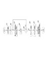
FIG. 1 is a block diagram showing the main configuration of
図1において、音声符号化装置100は、周波数領域変換部101、第1レイヤ符号化部102、第1レイヤ復号部103、減算器104、第2レイヤ符号化部105、および多重化部106を備える。
In FIG. 1,
周波数領域変換部101は、時間領域の入力信号を周波数領域の信号に変換し、得られる入力変換係数を第1レイヤ符号化部102および減算器104に出力する。
Frequency
第1レイヤ符号化部102は、周波数領域変換部101から入力される入力変換係数に対し符号化処理を行い、得られる第1レイヤ符号化データを第1レイヤ復号部103および多重化部106に出力する。
First
第1レイヤ復号部103は、第1レイヤ符号化部102から入力される第1レイヤ符号化データを用いて復号処理を行い、得られる第1レイヤ復号変換係数を減算器104に出力する。
First
減算器104は、周波数領域変換部101から入力される入力変換係数から、第1レイヤ復号部103から入力される第1レイヤ復号変換係数を減じ、得られる第1レイヤ誤差変換係数を第2レイヤ符号化部105に出力する。
The
第2レイヤ符号化部105は、減算器104から入力される第1レイヤ誤差変換係数に対し符号化処理を行い、得られる第2レイヤ符号化データを多重化部106に出力する。なお、第2レイヤ符号化部105の詳細については後述する。
Second
多重化部106は、第1レイヤ符号化部102から入力される第1レイヤ符号化データと、第2レイヤ符号化部105から入力される第2レイヤ符号化データとを多重化して、得られるビットストリームを通信路に出力する。
Multiplexing
図2は、第2レイヤ符号化部105の内部の構成を示すブロック図である。
FIG. 2 is a block diagram showing an internal configuration of second
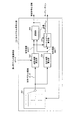
図2において、第2レイヤ符号化部105は、サブバンド構成部151、形状ベクトル符号化部152、ゲインベクトル構成部153、ゲインベクトル符号化部154、および多重化部155を備える。
2, second
サブバンド構成部151は、減算器104から入力される第1レイヤ誤差変換係数をM個のサブバンドに分割し、得られるM個のサブバンド変換係数を形状ベクトル符号化部152に出力する。ここで、第1レイヤ誤差変換係数をel(k)と表す場合、第m(0≦m≦M−1)サブバンド変換係数e(m,k)は、下記の式(1)で表される。

式(1)において、F(m)は、各サブバンド境界の周波数を表し、0≦F(0)<F(1)<…<F(M)≦FHの関係にある。ここで、FHは第1レイヤ誤差変換係数の最大周波数を表し、mは0≦m≦M−1の整数をとる。 In Formula (1), F (m) represents the frequency of each subband boundary, and has a relationship of 0 ≦ F (0) <F (1) <... <F (M) ≦ FH. Here, FH represents the maximum frequency of the first layer error conversion coefficient, and m is an integer of 0 ≦ m ≦ M−1.
形状ベクトル符号化部152は、サブバンド構成部151から順次入力されるM個のサブバンド変換係数それぞれに対し形状ベクトル量子化を行ってM個のサブバンドそれぞれの形状符号化情報を生成するとともに、M個のサブバンド変換係数それぞれのターゲットゲインを算出する。形状ベクトル符号化部152は、生成された形状符号化情報を多重化部155に出力し、ターゲットゲインをゲインベクトル構成部153に出力する。なお、形状ベクトル符号化部152の詳細については後述する。
The shape
ゲインベクトル構成部153は、形状ベクトル符号化部152から入力されるM個のターゲットゲインから1つのゲインベクトルを構成してゲインベクトル符号化部154に出力する。なお、ゲインベクトル構成部153の詳細については後述する。
The gain
ゲインベクトル符号化部154は、ゲインベクトル構成部153から入力されるゲインベクトルを目標値としてベクトル量子化を行い、得られるゲイン符号化情報を多重化部155に出力する。なお、ゲインベクトル符号化部154の詳細については後述する。
The gain
多重化部155は、形状ベクトル符号化部152から入力される形状符号化情報と、ゲインベクトル符号化部154から入力されるゲイン符号化情報とを多重化し、得られるビットストリームを第2レイヤ符号化データとして多重化部106に出力する。
The
図3は、第2レイヤ符号化部105における第2レイヤ符号化処理の手順を示すフロー図である。
FIG. 3 is a flowchart showing the procedure of second layer encoding processing in second
まず、ステップ(以下、「ST」と略称する。)1010において、サブバンド構成部151は、第1レイヤ誤差変換係数をM個のサブバンドに分割し、M個のサブバンド変換係数を構成する。
First, in step (hereinafter abbreviated as “ST”) 1010, subband configuring
次いで、ST1020において、第2レイヤ符号化部105は、サブバンドをカウントするサブバンドカウンタmを「0」に初期化する。
Next, in ST1020, second
次いで、ST1030において、形状ベクトル符号化部152は、第mサブバンド変換係数に対し形状ベクトル符号化を行い、第mサブバンドの形状符号化情報を生成するとともに、第mサブバンド変換係数のターゲットゲインを生成する。
Next, in ST1030, shape
次いで、ST1040において、第2レイヤ符号化部105は、サブバンドカウンタmを1インクリメントする。
Next, in ST1040, second
次いで、ST1050において、第2レイヤ符号化部105は、m<Mであるか否かを判定する。
Next, in ST1050, second
ST1050において、m<Mであると判定した場合(ST1050:「YES」)には、第2レイヤ符号化部105は、処理手順をST1030に戻す。
If it is determined in ST1050 that m <M (ST1050: “YES”), second
一方、ST1050において、m<Mでないと判定した場合(ST1050:「NO」)には、ゲインベクトル構成部153は、ST1060において、M個のターゲットゲインを用いて1つのゲインベクトルを構成する。
On the other hand, when it is determined in ST1050 that m <M is not satisfied (ST1050: “NO”), gain
次いで、ST1070において、ゲインベクトル符号化部154は、ゲインベクトル構成部153で構成されたゲインベクトルを目標値としてベクトル量子化を行い、ゲイン符号化情報を生成する。
Next, in
次いで、ST1080において、多重化部155は、形状ベクトル符号化部152で生成された形状符号化情報と、ゲインベクトル符号化部154で生成されたゲイン符号化情報とを多重化する。
Next, in ST1080, multiplexing
図4は、形状ベクトル符号化部152の内部の構成を示すブロック図である。
FIG. 4 is a block diagram showing an internal configuration of the shape
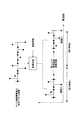
図4において、形状ベクトル符号化部152は、形状ベクトル符号帳521、相互相関算出部522、自己相関算出部523、探索部524、およびターゲットゲイン算出部525を備える。
In FIG. 4, shape
形状ベクトル符号帳521は、第1レイヤ誤差変換係数の形状を表す形状ベクトル候補を多数格納しており、探索部524から入力される制御信号に基づき、形状ベクトル候補を相互相関算出部522および自己相関算出部523に順次出力する。なお、一般的に、形状ベクトル符号帳は、実際に記憶領域を確保して形状ベクトル候補を記憶する形態をとる場合もあるし、またはあらかじめ定められた処理手順に従い形状ベクトル候補を構成する場合もある。後者の場合、実際に記憶領域を確保する必要はない。本実施の形態で用いる形状ベクトル符号帳はどちらでも良いが、以下では図4に示されているような形状ベクトル候補が記憶されている形状ベクトル符号帳521を持つことを前提として説明を行う。以下、形状ベクトル符号帳521に格納されている多数の形状ベクトル候補のうちの第i番目をc(i,k)と表す。ここで、kは、形状ベクトル候補を構成する複数の要素のうちの第k個目を示す。
The
相互相関算出部522は、下記の式(2)に従い、サブバンド構成部151から入力される第mサブバンド変換係数と、形状ベクトル符号帳521から入力される第i形状ベクトル候補との相互相関ccor(i)を算出し、探索部524、およびターゲットゲイン算出部525に出力する。
自己相関算出部523は、下記の式(3)に従い、形状ベクトル符号帳521から入力される形状ベクトル候補c(i,k)の自己相関acor(i)を算出し、探索部524、およびターゲットゲイン算出部525に出力する。
探索部524は、相互相関算出部522から入力される相互相関ccor(i)と、自己相関算出部523から入力される自己相関acor(i)とを用いて下記の式(4)で表される寄与度Aを算出し、寄与度Aの最大値が探索されるまで、形状ベクトル符号帳521に制御信号を出力する。探索部524は、寄与度Aが最大となる際の形状ベクトル候補のインデックスioptを最適インデックスとしてターゲットゲイン算出部525に出力するととともに、形状符号化情報として多重化部155に出力する。
ターゲットゲイン算出部525は、相互相関算出部522から入力される相互相関ccor(i)、自己相関算出部523から入力される自己相関acor(i)、および探索部524から入力される最適インデックスioptを用いて下記の式(5)に従いターゲットゲインを算出し、ゲインベクトル構成部153に出力する。
図5は、ゲインベクトル構成部153の内部の構成を示すブロック図である。
FIG. 5 is a block diagram illustrating an internal configuration of the gain
図5において、ゲインベクトル構成部153は、配置位置決定部531およびターゲットゲイン配置部532を備える。
In FIG. 5, the gain
配置位置決定部531は、初期値が「0」であるカウンタを備え、形状ベクトル符号化部152からターゲットゲインが入力される度にカウンタの値を1インクリメントし、カウンタの値がサブバンドの総数Mとなる場合、再びカウンタの値をゼロに設定する。ここで、Mは、ゲインベクトル構成部153において構成されるゲインベクトルのベクトル長でもあり、配置位置決定部531が備えるカウンタの処理は、カウンタの値をゲインベクトルのベクトル長で剰余をとることに相当する。すなわち、カウンタの値は「0」〜M−1までの整数である。配置位置決定部531は、カウンタの値が更新される度に、更新されたカウンタの値を配置情報としてターゲットゲイン配置部532に出力する。
The arrangement
ターゲットゲイン配置部532は、初期値がそれぞれ「0」であるM個のバッファ、および形状ベクトル符号化部152から入力されるターゲットゲインを各バッファに配置するスイッチを備え、このスイッチは、配置位置決定部531から入力される配置情報が示す値を番号とするバッファに、形状ベクトル符号化部152から入力されるターゲットゲインを配置する。
The target
図6は、ターゲットゲイン配置部532の動作を詳細に説明するための図である。
FIG. 6 is a diagram for explaining the operation of the target
図6において、スイッチに入力される配置情報が「0」である場合には、ターゲットゲインが第0バッファに配置され、配置情報がM−1である場合には、ターゲットゲインが第M−1バッファに配置される。全てのバッファにターゲットゲインが配置された場合、ターゲットゲイン配置部532は、M個のバッファに配置されたターゲットゲインからなるゲインベクトルをゲインベクトル符号化部154に出力する。
In FIG. 6, when the placement information input to the switch is “0”, the target gain is placed in the 0th buffer, and when the placement information is M−1, the target gain is the (M−1) th gain. Placed in the buffer. When target gains are arranged in all buffers, the target
図7は、ゲインベクトル符号化部154の内部の構成を示すブロック図である。
FIG. 7 is a block diagram showing an internal configuration of gain
図7において、ゲインベクトル符号化部154は、ゲインベクトル符号帳541、誤差算出部542、および探索部543を備える。
In FIG. 7, gain
ゲインベクトル符号帳541は、ゲインベクトルを表すゲインベクトル候補を多数格納しており、探索部543から入力される制御信号に基づき、ゲインベクトル候補を誤差算出部542に順次出力する。一般的に、ゲインベクトル符号帳は、実際に記憶領域を確保してゲインベクトル候補を記憶する形態をとる場合もあるし、またはあらかじめ定められた処理手順に従いゲインベクトル候補を構成する場合もある。後者の場合、実際に記憶領域を確保する必要はない。本実施の形態で用いるゲインベクトル符号帳はどちらでも良いが、以下では図7に示されているようなゲインベクトル候補が記憶されているゲインベクトル符号帳541を持つことを前提として説明を行う。以下、ゲインベクトル符号帳541に格納されている多数のゲインベクトル候補のうちの第j番目をg(j,m)と表す。ここで、mは、ゲインベクトル候補を構成するM個の要素のうちの第m個目を示す。
The
誤差算出部542は、ゲインベクトル構成部153から入力されるゲインベクトル、およびゲインベクトル符号帳541から入力されるゲインベクトル候補を用いて、下記の式(6)に従い、誤差E(j)を算出して探索部543に出力する。
式(6)において、mは、サブバンドの番号を示し、gv(m)は、ゲインベクトル構成部153から入力されるゲインベクトルを示す。
In Expression (6), m represents a subband number, and gv (m) represents a gain vector input from the gain
探索部543は、誤差算出部542から入力される誤差E(j)の最小値が探索されるまで、ゲインベクトル符号帳541に制御信号を出力し、誤差E(j)が最小となる際のゲインベクトル候補のインデックスjoptを探索し、ゲイン符号化情報として多重化部155に出力する。
図8は、本実施の形態に係る音声復号装置200の主要な構成を示すブロック図である。
FIG. 8 is a block diagram showing the main configuration of
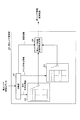
図8において、音声復号装置200は、分離部201、第1レイヤ復号部202、第2レイヤ復号部203、加算器204、切替部205、時間領域変換部206、およびポストフィルタ207を備える。
In FIG. 8,
分離部201は、通信路を経由して音声符号化装置100から伝送されるビットストリームを第1レイヤ符号化データおよび第2レイヤ符号化データに分離し、第1レイヤ符号化データを第1レイヤ復号部202に出力し、第2レイヤ符号化データを第2レイヤ復号部203に出力する。ただし、通信路の状況(輻輳の発生等)によっては、符号化データの一部分、例えば第2レイヤ符号化データが消失するか、または第1レイヤ符号化データおよび第2レイヤ符号化データを含む符号化データ全てが消失してしまう場合がある。そこで、分離部201は、受信した符号化データに第1レイヤ符号化データのみが含まれているか、または第1レイヤおよび第2レイヤ符号化データの両方が含まれているかを判定し、前者の場合にはレイヤ情報として「1」を切替部205に出力し、後者の場合にはレイヤ情報として「2」を切替部205に出力する。また、分離部201は、第1レイヤ符号化データおよび第2レイヤ符号化データを含む符号化データ全てが消失したと判定した場合には、所定の補償処理を行って第1レイヤ符号化データおよび第2レイヤ符号化データを生成し、第1レイヤ復号部202および第2レイヤ復号部203それぞれに出力し、レイヤ情報として「2」を切替部205に出力する。
Separating
第1レイヤ復号部202は、分離部201から入力される第1レイヤ符号化データを用いて復号処理を行い、得られる第1レイヤ復号変換係数を加算器204および切替部205に出力する。
First
第2レイヤ復号部203は、分離部201から入力される第2レイヤ符号化データを用いて復号処理を行い、得られる第1レイヤ誤差変換係数を加算器204に出力する。
Second
加算器204は、第1レイヤ復号部202から入力される第1レイヤ復号変換係数と、第2レイヤ復号部203から入力される第1レイヤ誤差変換係数とを加算し、得られる第2レイヤ復号変換係数を切替部205に出力する。
The
切替部205は、分離部201から入力されるレイヤ情報が「1」である場合には、第1レイヤ復号変換係数を復号変換係数として時間領域変換部206に出力し、レイヤ情報が「2」である場合には、第2レイヤ復号変換係数を復号変換係数として時間領域変換部206に出力する。
When the layer information input from the
時間領域変換部206は、切替部205から入力される復号変換係数を時間領域の信号に変換し、得られる復号信号をポストフィルタ207に出力する。
The time
ポストフィルタ207は、時間領域変換部206より入力される復号信号に対して、ホルマント強調、ピッチ強調、およびスペクトル傾斜調整等のポストフィルタ処理を行ってから復号音声として出力する。
The
図9は、第2レイヤ復号部203の内部の構成を示すブロック図である。
FIG. 9 is a block diagram showing an internal configuration of second
図9において、第2レイヤ復号部203は、分離部231、形状ベクトル符号帳232、ゲインベクトル符号帳233、および第1レイヤ誤差変換係数生成部234を備える。
In FIG. 9, second
分離部231は、分離部201から入力される第2レイヤ符号化データをさらに形状符号化情報およびゲイン符号化情報に分離し、形状符号化情報を形状ベクトル符号帳232に出力し、ゲイン符号化情報をゲインベクトル符号帳233に出力する。
Separating
形状ベクトル符号帳232は、図4の形状ベクトル符号帳521が備える多数の形状ベクトル候補と同様な形状ベクトル候補を備え、分離部231から入力される形状符号化情報が示す形状ベクトル候補を第1レイヤ誤差変換係数生成部234に出力する。
The
ゲインベクトル符号帳233は、図7のゲインベクトル符号帳541が備える多数のゲインベクトル候補と同様なゲインベクトル候補を備え、分離部231から入力されるゲイン符号化情報が示すゲインベクトル候補を第1レイヤ誤差変換係数生成部234に出力する。
The
第1レイヤ誤差変換係数生成部234は、形状ベクトル符号帳232から入力される形状ベクトル候補に、ゲインベクトル符号帳233から入力されるゲインベクトル候補を乗じて第1レイヤ誤差変換係数を生成し、加算器204に出力する。具体的には、ゲインベクトル符号帳233から入力されるゲインベクトル候補を構成するM個の要素のうちの第m番目の要素を、すなわち第mサブバンド変換係数のターゲットゲインを、形状ベクトル符号帳232から順次入力される第m番目の形状ベクトル候補に乗じる。ここで、Mは前述したようにサブバンドの総数を示す。
The first layer error conversion
このように、本実施の形態によれば、サブバンド毎の目標信号(本実施の形態では第1レイヤ誤差変換係数)のスペクトルの形状を符号化し(形状ベクトルの符号化)、次に目標信号と符号化された形状ベクトルとの歪を最小とするターゲットゲイン(理想ゲイン)を算出し、これを符号化する(ターゲットゲインの符号化)構成を採る。これにより、従来技術のように、サブバンド毎の目標信号のエネルギ成分を符号化し(ゲインまたはスケールファクタの符号化)、これを用いて目標信号を正規化した後にスペクトルの形状を符号化(形状ベクトルの符号化)する方式に比べ、目標信号との歪を最小化するターゲットゲインを符号化する本実施の形態の方が原理的に符号化歪を小さくすることができる。なお、ターゲットゲインは、式(5)に示されるように、形状ベクトルを符号化してはじめて算出できるパラメータであるため、従来技術のように形状ベクトルの符号化がゲイン情報の符号化よりも時間的に後段に位置する符号化方式ではターゲットゲインをゲイン情報の符号化の対象にすることができないのに対し、本実施の形態ではそれが可能となり、より符号化歪を小さくすることができる。 Thus, according to the present embodiment, the shape of the spectrum of the target signal for each subband (first layer error transform coefficient in the present embodiment) is encoded (encoding of the shape vector), and then the target signal The target gain (ideal gain) that minimizes the distortion between the encoded shape vector and the encoded shape vector is calculated and encoded (target gain encoding). Thus, as in the prior art, the energy component of the target signal for each subband is encoded (gain or scale factor encoding), and after normalizing the target signal using this, the spectrum shape is encoded (shape) Compared with the vector encoding method, the present embodiment of encoding the target gain that minimizes the distortion with the target signal can in principle reduce the encoding distortion. Since the target gain is a parameter that can be calculated only after the shape vector is encoded as shown in Equation (5), the shape vector encoding is more time-consuming than the gain information encoding as in the prior art. On the other hand, in the encoding method located in the subsequent stage, the target gain cannot be a target for encoding gain information, whereas in the present embodiment, this is possible and encoding distortion can be further reduced.
また本実施の形態では、複数の隣接するサブバンドのターゲットゲインを用いて1つのゲインベクトルを構成し、これを符号化する構成を採る。目標信号の隣接するサブバンド間のエネルギ情報は類似していることから、隣接サブバンド間のターゲットゲインの類似度も同様に高い。このため、ベクトル空間上でのゲインベクトルの分布に偏りが生じることになる。ゲイン符号帳に含まれるゲインベクトル候補をこの偏りに適合するように配置することにより、ターゲットゲインの符号化歪を低減させることができる。 In this embodiment, a configuration is adopted in which one gain vector is configured using target gains of a plurality of adjacent subbands, and this is encoded. Since the energy information between adjacent subbands of the target signal is similar, the similarity of the target gain between adjacent subbands is also high. For this reason, the distribution of the gain vector in the vector space is biased. By arranging the gain vector candidates included in the gain codebook so as to match this bias, the encoding distortion of the target gain can be reduced.
このように本実施の形態によれば、目標信号の符号化歪を低減させることができ、このため復号音声の音質を向上させることができる。さらに、本実施の形態によれば、音声の母音や音楽信号のようにトーナリティが強い信号のスペクトルに対しても、スペクトルの形状を正確に符号化できるため、音質を向上させることができる。 As described above, according to the present embodiment, it is possible to reduce the encoding distortion of the target signal, and thus improve the sound quality of the decoded speech. Furthermore, according to the present embodiment, the shape of the spectrum can be accurately encoded even for a spectrum of a signal having strong tonality such as a voice vowel or a music signal, so that the sound quality can be improved.
また、従来技術では、サブバンドゲインと形状ベクトルという2つのパラメータを用いてスペクトルの大きさを制御している。これは、スペクトルの大きさをサブバンドゲインと形状ベクトルの2つのパラメータに分けて表していると捉えることができる。それに対して本実施の形態では、ターゲットゲインという1つのパラメータのみでスペクトルの大きさを制御している。さらにこのターゲットゲインは、符号化された形状ベクトルに対して符号化歪を最小にする理想的なゲイン(理想ゲイン)である。このため、従来技術と比べて効率的な符号化を行うことができ、低ビットレート時においても高音質化を実現することができる。 In the prior art, the magnitude of the spectrum is controlled using two parameters, a subband gain and a shape vector. This can be regarded as representing the magnitude of the spectrum divided into two parameters, a subband gain and a shape vector. In contrast, in the present embodiment, the magnitude of the spectrum is controlled by only one parameter called the target gain. Furthermore, this target gain is an ideal gain (ideal gain) that minimizes encoding distortion with respect to the encoded shape vector. For this reason, the encoding can be performed more efficiently than in the prior art, and high sound quality can be realized even at a low bit rate.
なお、本実施の形態では、サブバンド構成部151により周波数領域を複数のサブバンドに分割しサブバンド毎に符号化を行う場合を例にとって説明したが、本発明はこれに限定されず、ゲインベクトル符号化よりも形状ベクトル符号化を時間的に先に行えば、複数のサブバンドを纏めて符号化しても良く、本実施の形態と同様に母音のようにトーナリティが強い信号スペクトルの形状をより正確に符号化できる効果が得られる。例えば、始めに形状ベクトル符号化を行い、その後に形状ベクトルをサブバンドに分割してサブバンド毎のターゲットゲインを算出してゲインベクトルを構成し、ゲインベクトルの符号化を行う構成であっても良い。
In the present embodiment, the case where the frequency region is divided into a plurality of subbands by the
また、本実施の形態では、第2レイヤ符号化部105において多重化部155(図2参照)を備える場合を例にとって説明したが、本発明はこれに限定されず、形状ベクトル符号化部152およびゲインベクトル符号化部154それぞれは、形状符号化情報およびゲイン符号化情報それぞれを直接音声符号化装置100の多重化部106(図1参照)に出力しても良い。これに対応して、第2レイヤ復号部203も分離部231(図9参照)を備えず、音声復号装置200の分離部201(図8参照)がビットストリームを用いて、直接形状符号化情報およびゲイン符号化情報を分離し、直接形状ベクトル符号帳232およびゲインベクトル符号帳233それぞれに出力しても良い。
In the present embodiment, the case where second
また、本実施の形態では、相互相関算出部522は、式(2)に従い相互相関ccor(i)を算出する場合を例にとって説明したが、本発明はこれに限定されず、聴感的に重要なスペクトルに大きな重みを与えて聴感的に重要なスペクトルの寄与を大きくすることを目的に、相互相関算出部522は、次の式(7)に従い相互相関ccor(i)を算出しても良い。
式(7)において、w(k)は、人間の聴感特性に関連する重みを示し、聴感特性上、重要度が高い周波数ほどw(k)が大きくなる。 In Expression (7), w (k) represents a weight related to human auditory characteristics, and w (k) increases as the importance increases in the auditory characteristics.
また、同様に、自己相関算出部523も、聴感的に重要なスペクトルに大きな重みを与えることにより聴感的に重要なスペクトルの寄与を大きくするために、次の式(8)に従い自己相関acor(i)を算出しても良い。
また、同様に、誤差算出部542も、聴感的に重要なスペクトルに大きな重みを与えることにより聴感的に重要なスペクトルの寄与を大きくするために、次の式(9)に従い誤差E(j)を算出しても良い。
式(7)、式(8)および式(9)における重みとしては、例えば、入力信号または下位レイヤの復号信号(第1レイヤ復号信号)を基に算出された聴覚マスキング閾値や、人間の聴覚のラウドネス特性を利用して求めたものを用いても良い。 As weights in Expression (7), Expression (8), and Expression (9), for example, an auditory masking threshold calculated based on an input signal or a lower layer decoded signal (first layer decoded signal), human hearing, What is obtained by using the loudness characteristic of may be used.
また、本実施の形態では、形状ベクトル符号化部152が自己相関算出部523を備える場合を例にとって説明したが、本発明はこれに限定されず、式(3)に従い算出される自己相関係数acor(i)、または式(8)に従い算出される自己相関係数acor(i)が定数となる場合には、自己相関acor(i)をあらかじめ算出しておいて、自己相関算出部523を設けず、あらかじめ算出された自己相関acor(i)を用いても良い。
In the present embodiment, the case where the shape
(実施の形態2)
本発明の実施の形態2に係る音声符号化装置および音声復号装置は、実施の形態1に示した音声符号化装置100および音声復号装置200と同様な構成を有して同様な動作を行い、用いる形状ベクトル符号帳のみにおいて相違する。
(Embodiment 2)
The speech encoding apparatus and speech decoding apparatus according to
図10は、本実施の形態に係る形状ベクトル符号帳を説明するための図であり、母音の一例として日本語の母音「オ」のスペクトルを示す。 FIG. 10 is a diagram for explaining the shape vector codebook according to the present embodiment, and shows a spectrum of a Japanese vowel “o” as an example of a vowel.
図10において、横軸は周波数を示し、縦軸はスペクトルの対数エネルギを示す。図10に示すように、母音のスペクトルにおいては、多数のピーク形状が観察され、強いトーナリティを示す。また、Fxは多数のピーク形状のうちの1つが位置する周波数を示す。 In FIG. 10, the horizontal axis indicates the frequency, and the vertical axis indicates the logarithmic energy of the spectrum. As shown in FIG. 10, in the spectrum of vowels, a number of peak shapes are observed, indicating a strong tonality. Fx indicates the frequency at which one of the many peak shapes is located.
図11は、本実施の形態に係る形状ベクトル符号帳に含まれる多数の形状ベクトル候補を例示する図である。 FIG. 11 is a diagram illustrating a large number of shape vector candidates included in the shape vector codebook according to the present embodiment.
図11において、(a)は、形状ベクトル候補において振幅値が「+1」または「−1」であるサンプル(すなわちパルス)を例示し、(b)は、振幅値が「0」であるサンプルを例示する。図11に示す複数の形状ベクトル候補は、任意の周波数に位置するパルスを複数含む。従って、図11に示すような形状ベクトル候補を探索することによって、図10に示すようなトーナリティの強いスペクトルをより正確に符号化することができる。具体的には、図10に示されているようなトーナリティの強い信号に対しては、ピーク形状が位置する周波数に対応する振幅値、例えば図10に示すFxの位置の振幅値が「+1」または「−1」のパルス(図11に示すサンプル(a))となり、ピーク形状以外の周波数の振幅値が「0」(図11に示すサンプル(b))となるように、形状ベクトル候補を探索により決定する。 In FIG. 11, (a) illustrates a sample (that is, a pulse) whose amplitude value is “+1” or “−1” in the shape vector candidate, and (b) illustrates a sample whose amplitude value is “0”. Illustrate. The plurality of shape vector candidates shown in FIG. 11 include a plurality of pulses located at arbitrary frequencies. Therefore, by searching for a shape vector candidate as shown in FIG. 11, a spectrum with strong tonality as shown in FIG. 10 can be encoded more accurately. Specifically, for a signal with strong tonality as shown in FIG. 10, the amplitude value corresponding to the frequency at which the peak shape is located, for example, the amplitude value at the Fx position shown in FIG. Alternatively, the shape vector candidate is selected so that the pulse value is “−1” (sample (a) shown in FIG. 11) and the amplitude value of the frequency other than the peak shape is “0” (sample (b) shown in FIG. 11). Determine by searching.
形状ベクトル符号化よりもゲイン符号化を時間的に先に行う従来技術では、サブバンドゲインの量子化、およびサブバンドゲインを用いたスペクトルの正規化を行った後にスペクトルの微細成分(形状ベクトル)の符号化を行う。低ビットレート化によってサブバンドゲインの量子化歪が大きくなると正規化の効果が小さくなり、正規化後のスペクトルのダイナミックレンジを十分に小さくできない。これにより、次の形状ベクトル符号化部の量子化ステップを粗くしなければならなくなり、その結果、量子化歪が増大してしまう。この量子化歪の影響により、スペクトルのピーク形状が減衰してしまったり(真のピーク形状の喪失)、ピーク形状ではないスペクトルが増幅してピーク形状のように現れてしまう(偽のピーク形状の出現)。これによりピーク形状の周波数位置が変わってしまい、ピーク性の強い音声信号の母音部や音楽信号の音質劣化を引き起こす。 In the prior art in which gain encoding is performed temporally before shape vector encoding, subband gain quantization and spectrum normalization using subband gain are performed, and then the fine component of the spectrum (shape vector) Is encoded. If the quantization distortion of the subband gain increases due to the low bit rate, the effect of normalization is reduced, and the dynamic range of the spectrum after normalization cannot be sufficiently reduced. As a result, the quantization step of the next shape vector encoding unit must be roughened, resulting in an increase in quantization distortion. Due to the influence of this quantization distortion, the peak shape of the spectrum is attenuated (loss of the true peak shape), or the spectrum that is not the peak shape is amplified and appears like a peak shape (a false peak shape Appearance). As a result, the frequency position of the peak shape is changed, and the sound quality of the vowel part of the voice signal having a strong peak property or the music signal is deteriorated.
それに対して本実施の形態では、先に形状ベクトルを決定し、次にターゲットゲインを算出して、これを量子化する構成を採る。本実施の形態のようにベクトルの要素のいくつかが+1または−1のパルスで表される形状ベクトルを有するとき、先に形状ベクトルを決定するということは当該パルスを立てる周波数位置を先に決定することを意味する。ゲインの量子化の影響を受けずにパルスを立てる周波数位置を決定できるため、真のピーク形状の喪失や偽のピーク形状の出現といった現象を引き起こすことがなく、前述した従来技術の課題を回避することができる。 On the other hand, in the present embodiment, a configuration is adopted in which the shape vector is determined first, then the target gain is calculated and quantized. When some of the vector elements have a shape vector represented by a +1 or -1 pulse as in the present embodiment, determining the shape vector first determines the frequency position where the pulse is raised first. It means to do. Since the frequency position where the pulse is raised can be determined without being influenced by the gain quantization, it does not cause a phenomenon such as the loss of the true peak shape or the appearance of the false peak shape, thereby avoiding the above-mentioned problems of the prior art. be able to.
このように、本実施の形態によれば、先に形状ベクトルを決定する構成で、かつパルスを含む形状ベクトルからなる形状ベクトル符号帳を用いて形状ベクトル符号化を行うため、ピーク性の強いスペクトルの周波数を特定し、そこにパルスを立てることができる。これにより、音声信号の母音や音楽信号のようにトーナリティが強いスペクトルを持つ信号を高品質に符号化することができる。 As described above, according to the present embodiment, since the shape vector coding is performed using the shape vector codebook composed of the shape vector including the pulse with the configuration in which the shape vector is determined first, the spectrum having a strong peak characteristic is used. The frequency can be specified and a pulse can be set there. As a result, a signal having a spectrum with strong tonality such as a vowel of a voice signal or a music signal can be encoded with high quality.
(実施の形態3)
本発明の実施の形態3においては、音声信号のスペクトルの中でトーナリティの強い範囲(領域)を選択し、選択された範囲に限定して符号化を行う点において、実施の形態1と相違する。
(Embodiment 3)
The third embodiment of the present invention is different from the first embodiment in that a range (region) having a high tonality is selected from the spectrum of the audio signal, and encoding is limited to the selected range. .
本発明の実施の形態3に係る音声符号化装置は、実施の形態1に係る音声符号化装置100(図1参照)と同様な構成を有しており、第2レイヤ符号化部105の代わりに第2レイヤ符号化部305を有する点のみにおいて音声符号化装置100と相違する。このため、本実施の形態に係る音声符号化装置の全体構成は図示せず、詳細な説明を省略する。
The speech coding apparatus according to
図12は、本実施の形態に係る第2レイヤ符号化部305の内部の構成を示すブロック図である。なお、第2レイヤ符号化部305は、実施の形態1に示した第2レイヤ符号化部105(図1参照)と同様の基本的構成を有しており、同一の構成要素には同一の符号を付し、その説明を省略する。 FIG. 12 is a block diagram showing an internal configuration of second layer encoding section 305 according to the present embodiment. Second layer encoding section 305 has the same basic configuration as second layer encoding section 105 (see FIG. 1) shown in the first embodiment, and the same components are the same. Reference numerals are assigned and explanations thereof are omitted.
第2レイヤ符号化部305は、範囲選択部351をさらに具備する点において、実施の形態1に係る第2レイヤ符号化部105と相違する。なお、第2レイヤ符号化部305の形状ベクトル符号化部352は、第2レイヤ符号化部105の形状ベクトル符号化部152とは処理の一部に相違点があり、それを示すために異なる符号を付す。
Second layer encoding section 305 is different from second
範囲選択部351は、サブバンド構成部151から入力されるM個のサブバンド変換係数のうち、任意数の隣接する複数のサブバンドを用いて複数の範囲を構成し、各範囲のトーナリティを算出する。範囲選択部351は、トーナリティが最も高い範囲を選択し、選択された範囲を示す範囲情報を多重化部155と形状ベクトル符号化部352に出力する。なお、範囲選択部351における範囲選択処理の詳細については後述する。
The
形状ベクトル符号化部352は、範囲選択部351より入力される範囲情報に基づき、範囲に含まれるサブバンド変換係数をサブバンド構成部151から入力されるサブバンド変換係数の中から選択し、選択されたサブバンド変換係数に対し形状ベクトル量子化を行う点のみにおいて、実施の形態1に係る形状ベクトル符号化部152と相違し、ここでは詳細な説明を省略する。
Based on the range information input from the
図13は、範囲選択部351における範囲選択処理を説明するための図である。
FIG. 13 is a diagram for explaining range selection processing in the
図13において、横軸は周波数を示し、縦軸はスペクトルの対数エネルギを示す。また、図13においては、サブバンドの総数Mが「8」であり、第0サブバンド〜第3サブバンドを用いて範囲0を構成し、第2サブバンド〜第5サブバンドを用いて範囲1を構成し、第4サブバンド〜第7サブバンドを用いて範囲2を構成する場合を例示する。範囲選択部351において、所定の範囲のトーナリティを評価する指標として、所定の範囲に含まれている複数のサブバンド変換係数の幾何平均と算術平均との比を用いて表されるスペクトラルフラットネスメジャー(SFM:Spectral Flatness Measure)を算出する。SFMは「0」〜「1」までの値をとり、「0」に近いほどより強いトーナリティを示す。従って、各範囲でSFMを算出し、SFMが「0」に最も近い範囲が選択されることになる。
In FIG. 13, the horizontal axis indicates the frequency, and the vertical axis indicates the logarithmic energy of the spectrum. In FIG. 13, the total number M of subbands is “8”, the
本実施の形態に係る音声復号装置は、実施の形態1に係る音声復号装置200(図8参照)と同様な構成を有しており、第2レイヤ復号部203の代わりに第2レイヤ復号部403を有する点のみにおいて音声復号装置200と相違する。このため、本実施の形態に係る音声復号装置の全体構成は図示せず、詳細な説明を省略する。
The speech decoding apparatus according to the present embodiment has the same configuration as speech decoding apparatus 200 (see FIG. 8) according to
図14は、本実施の形態に係る第2レイヤ復号部403の内部の構成を示すブロック図である。なお、第2レイヤ復号部403は、実施の形態1に示した第2レイヤ復号部203と同様の基本的構成を有しており、同一の構成要素には同一の符号を付し、その説明を省略する。
FIG. 14 is a block diagram showing an internal configuration of second layer decoding section 403 according to the present embodiment. Second layer decoding section 403 has the same basic configuration as second
第2レイヤ復号部403の分離部431および第1レイヤ誤差変換係数生成部434は、第2レイヤ復号部203の分離部231および第1レイヤ誤差変換係数生成部234と処理の一部に相違点があり、それを示すために異なる符号を付す。
The
分離部431は、形状符号化情報およびゲイン符号化情報のほかに、範囲情報をさらに分離して第1レイヤ誤差変換係数生成部434に出力する点のみにおいて、実施の形態1に示した分離部231と相違し、ここでは、詳細な説明を省略する。
第1レイヤ誤差変換係数生成部434は、形状ベクトル符号帳232から入力される形状ベクトル候補に、ゲインベクトル符号帳233から入力されるゲインベクトル候補を乗じて第1レイヤ誤差変換係数を生成し、これを範囲情報が示す範囲に含まれるサブバンドに配置して加算器204に出力する。
The first layer error conversion
このように、本実施の形態によれば、音声符号化装置はトーナリティが最も高い範囲を選択し、選択された範囲において、各サブバンドのゲインよりも形状ベクトルを時間的に先に符号化する。これにより、音声の母音や音楽信号のようにトーナリティが強い信号のスペクトルの形状をさらに正確に符号化しつつ、選択された範囲でのみ符号化を行うため符号化ビットレートを低減することができる。 As described above, according to the present embodiment, the speech encoding apparatus selects a range having the highest tonality, and encodes a shape vector earlier than the gain of each subband in the selected range. . As a result, the encoding bit rate can be reduced because encoding is performed only within a selected range while more accurately encoding the spectrum shape of a signal having strong tonality such as a vowel of a voice or a music signal.
なお、本実施の形態では所定の各範囲のトーナリティを評価する指標としてSFMを算出する場合を例にとって説明したが、本発明はこれに限定されず、例えば、所定の範囲の平均エネルギとトーナリティの大きさとの関連が強いことから、所定の範囲に含まれる変換係数の平均エネルギをトーナリティ評価の指標として算出しても良い。これによって、SFMを求めるよりも演算量を低減することができる。 In this embodiment, the case where the SFM is calculated as an index for evaluating the tonality of each predetermined range has been described as an example. However, the present invention is not limited to this, and for example, the average energy and the tonality of the predetermined range are calculated. Since the relationship with the magnitude is strong, the average energy of the conversion coefficients included in the predetermined range may be calculated as an index for tonality evaluation. As a result, the amount of calculation can be reduced as compared to obtaining SFM.
具体的には、範囲選択部351は、下記の式(10)に従い、範囲jに含まれる第1レイヤ誤差変換係数e1(k)のエネルギER(j)を算出する。
この式において、jは範囲を特定する識別子、FRL(j)は範囲jの最低周波数、FRH(j)は範囲jの最高周波数を表す。範囲選択部351は、このように範囲のエネルギER(j)を求め、次に、第1レイヤ誤差変換係数のエネルギが最も大きい範囲を特定し、この範囲に含まれる第1レイヤ誤差変換係数を符号化する。
In this equation, j represents an identifier for specifying the range, FRL (j) represents the lowest frequency in the range j, and FRH (j) represents the highest frequency in the range j. The
また、下記の式(11)に従い、人間の聴感特性を反映した重み付けを行って第1レイヤ誤差変換係数のエネルギを求めても良い。
かかる場合、聴感特性上の重要度が高い周波数ほど重みw(k)をより大きくして、その周波数を含む範囲が選択されやすいようにし、重要度の低い周波数ほど重みw(k)をより小さくして、その周波数を含む範囲が選択されにくいようにする。これにより、聴感的に重要な帯域ほど優先的に選択されるため、復号音声の音質を向上することができる。この重みw(k)としては、例えば、入力信号または下位レイヤの復号信号(第1レイヤ復号信号)を基に算出された聴覚マスキング閾値や、人間の聴覚のラウドネス特性を利用して求めたものを用いても良い。 In such a case, the weight w (k) is increased as the frequency having higher importance in the auditory characteristic so that the range including the frequency is easily selected, and the weight w (k) is decreased as the frequency having lower importance. Thus, it is difficult to select a range including the frequency. As a result, a band that is audibly important is preferentially selected, so that the quality of the decoded speech can be improved. The weight w (k) is obtained using, for example, an auditory masking threshold calculated based on an input signal or a lower layer decoded signal (first layer decoded signal) or a loudness characteristic of human hearing. May be used.
また、範囲選択部351は、所定の周波数(基準周波数)より低い周波数に配置された範囲の中から選択を行う構成であっても良い。
The
図15は、範囲選択部351において、所定の周波数(基準周波数)より低い周波数に配置された範囲の中から選択を行う方法を説明するための図である。
FIG. 15 is a diagram for describing a method of performing selection from a range arranged at a frequency lower than a predetermined frequency (reference frequency) in the
図15においては、所定の基準周波数Fyよりも低い帯域に8つの選択範囲の候補が配置される場合を例にあげ説明する。これらの8つの範囲は、それぞれF1、F2、…、F8を起点として所定長さの帯域からなり、範囲選択部351は、これらの8つの候補の中から、上述した選択方法に基づいて1つの範囲を選択する。これにより、所定の基準周波数Fyよりも低い周波数に位置する範囲が選択される。このように、低域(または低中域)を重視して符号化を行う利点は以下の通りである。
In FIG. 15, a case where eight selection range candidates are arranged in a band lower than a predetermined reference frequency Fy will be described as an example. Each of these eight ranges is composed of a band of a predetermined length starting from F1, F2,..., F8, and the
音声信号の特徴の1つである調波構造(またはハーモニクス構造と称す)、すなわち、ある周波数間隔でスペクトルがピーク状に現れる構造は、高域部に比べて低域部にピークが大きく現れる。符号化処理によって生じる量子化誤差(誤差スペクトルまたは誤差変換係数)においても同様にピーク性が残り、高域部よりは低域部のピーク性が強い。そのため、低域部の誤差スペクトルのエネルギが高域部と比べて小さい場合でも、誤差スペクトルのピーク性が強いため、誤差スペクトルが聴覚マスキング閾値(人間が音を感じ取ることのできる閾値)を超えやすく、聴感的な音質劣化を引き起こす。つまり、誤差スペクトルのエネルギが小さくても、低域部は高域部よりも聴感的な感度が高くなる。よって、範囲選択部351は、所定の周波数より低い周波数に配置された候補の中から範囲を選択する構成をとることにより、誤差スペクトルのピーク性が強い低域部の中から符号化の対象となる範囲を特定し、復号音声の音質を向上することができる。
A harmonic structure (or a harmonic structure) that is one of the characteristics of an audio signal, that is, a structure in which a spectrum appears in a peak shape at a certain frequency interval, has a peak that appears larger in the low frequency region than in the high frequency region. Similarly, the peak property remains in the quantization error (error spectrum or error conversion coefficient) generated by the encoding process, and the peak property in the low frequency region is stronger than the high frequency region. Therefore, even when the energy of the low-frequency part error spectrum is small compared to the high-frequency part, the error spectrum has a strong peak of the error spectrum, so the error spectrum is likely to exceed the auditory masking threshold (threshold that allows humans to feel the sound). , Causing auditory sound quality degradation. That is, even if the energy of the error spectrum is small, the low frequency part has higher auditory sensitivity than the high frequency part. Therefore, the
また、符号化対象となる範囲の選択方法として、過去のフレームで選択した範囲に関連付けて現フレームの範囲を選択しても良い。例えば、(1)前フレームで選択した範囲の近傍に位置する範囲の中から現フレームの範囲を決定する、(2)前フレームで選択した範囲の近傍に現フレームの範囲の候補を再配置し、その再配置された範囲の候補の中から現フレームの範囲を決定する、(3)範囲情報を数フレームに1度の割合で伝送し、範囲情報を伝送しないフレームでは過去に伝送された範囲情報が表す範囲を用いる(範囲情報の間欠伝送)などの方法が挙げられる。 Further, as a method for selecting a range to be encoded, the range of the current frame may be selected in association with the range selected in the past frame. For example, (1) the range of the current frame is determined from the range located in the vicinity of the range selected in the previous frame. (2) the current frame range candidates are rearranged in the vicinity of the range selected in the previous frame. The range of the current frame is determined from among the rearranged range candidates. (3) Range information transmitted at a rate of once every several frames and previously transmitted ranges for frames that do not transmit range information. A method such as using a range represented by information (intermittent transmission of range information) may be used.
また、範囲選択部351は、図16に示すように全帯域をあらかじめ複数の部分帯域に分割して、各部分帯域の中から各々1つの範囲を選択し、各部分帯域の選択された範囲を結合して、この結合範囲を符号化対象としても良い。図16では、部分帯域の数が2であって、低域部をカバーするように部分帯域1が設定され、高域部をカバーするように部分帯域2が設定される場合を例示する。なお、部分帯域1および部分帯域2は、それぞれ複数の範囲から構成される。範囲選択部351は、部分帯域1および部分帯域2の中から、それぞれ1つの範囲を選択する。例えば、図16に示すように、部分帯域1においては範囲2が選択され、部分帯域2においては範囲4が選択される。以下、部分帯域1の中から選択された範囲を示す情報を第1部分帯域範囲情報と呼び、部分帯域2の中から選択された範囲を示す情報を第2部分帯域範囲情報と呼ぶ。次いで、範囲選択部351は、部分帯域1の中から選択された範囲と、部分帯域2の中から選択された範囲とを結合して結合範囲を構成する。この結合範囲が範囲選択部351において選択された範囲となり、形状ベクトル符号化部352は、この結合範囲に対して形状ベクトル符号化を行う。
Further, the
図17は、部分帯域の数がNである場合に対応する範囲選択部351の構成を示すブロック図である。図17において、サブバンド構成部151から入力されるサブバンド変換係数は、部分帯域1選択部511−1〜部分帯域N選択部511−Nそれぞれに与えられる。各々の部分帯域n選択部511−n(n=1〜N)は、各部分帯域nの中から1つの範囲を選択し、選択した範囲を示す情報、すなわち第n部分帯域範囲情報を範囲情報構成部512に出力する。範囲情報構成部512は、部分帯域1選択部511−1〜部分帯域N選択部511−Nから入力される各第n部分帯域範囲情報(n=1〜N)が示す各範囲を結合して結合範囲を得る。そして、範囲情報構成部512は、結合範囲を示す情報を範囲情報として形状ベクトル符号化部352および多重化部155に出力する。
FIG. 17 is a block diagram illustrating a configuration of the
図18は、範囲情報構成部512において範囲情報を構成する様子を例示する図である。図18に示すように、範囲情報構成部512は、第1部分帯域範囲情報(A1ビット)〜第N部分帯域範囲情報(ANビット)を順番に並べて範囲情報を構成する。ここで、各第n部分帯域範囲情報のビット長Anは、各部分帯域nに含まれる候補範囲の数により決まり、それぞれ異なる値を有しても良い。
FIG. 18 is a diagram illustrating a state in which range information is configured in the range
図19は、図17に示した範囲選択部351に対応する第1レイヤ誤差変換係数生成部434(図14参照)の動作を説明するための図である。ここでは、部分帯域の数が2である場合を例にとる。第1レイヤ誤差変換係数生成部434は、形状ベクトル符号帳232から入力される形状ベクトル候補にゲインベクトル符号帳233から入力されるゲインベクトル候補を乗じる。そして、第1レイヤ誤差変換係数生成部434は、部分帯域1および部分帯域2各々の範囲情報が示す各範囲に上記のゲイン候補乗算後の形状ベクトル候補を配置する。このようにして求められた信号は、第1レイヤ誤差変換係数として出力される。
FIG. 19 is a diagram for explaining the operation of the first layer error conversion coefficient generation unit 434 (see FIG. 14) corresponding to the
図16に示すような範囲選択方法によれば、各々の部分帯域の中から1つの範囲が決定されるため、部分帯域に少なくとも1つの復号スペクトルを配置することが可能となる。従って、音質を改善したい複数の帯域をあらかじめ設定しておくことにより、全帯域の中から1つの範囲のみを選択する範囲選択方法よりも復号音声の品質を向上することができる。例えば低域部と高域部との両者の品質改善を同時に図りたい場合などに、図16に示すような範囲選択方法は有効である。 According to the range selection method as shown in FIG. 16, since one range is determined from each partial band, at least one decoded spectrum can be arranged in the partial band. Therefore, by setting in advance a plurality of bands whose sound quality is to be improved, the quality of the decoded speech can be improved as compared with the range selection method in which only one range is selected from all the bands. For example, the range selection method shown in FIG. 16 is effective when it is desired to simultaneously improve the quality of both the low frequency region and the high frequency region.
なお、図16に示す範囲選択方法のバリエーションとして、図20に例示しているように特定の部分帯域において常に固定の範囲が選択されるようにしても良い。図20に示す例では、部分帯域2において常に範囲4が選択され、これが結合範囲の一部になっている。図20に示した範囲選択方法によれば、図16に示した範囲選択方法の効果と同様に、音質を改善したい帯域をあらかじめ設定しておくことが可能となり、かつ、例えば、部分帯域2の部分帯域範囲情報が不用となるため、範囲情報を表すためのビット数をより小さくすることができる。
As a variation of the range selection method shown in FIG. 16, a fixed range may always be selected in a specific partial band as illustrated in FIG. In the example shown in FIG. 20, the range 4 is always selected in the
また、図20は、高域部(部分帯域2)において常に固定の範囲が選択される場合を例にとって示しているが、これに限定されず、低域部(部分帯域1)において常に固定の範囲が選択されるようにしても良いし、また図20には図示されていない中域部の部分帯域において、常に固定の範囲が選択されるようにしても良い。 FIG. 20 shows an example in which a fixed range is always selected in the high frequency band (partial band 2). However, the present invention is not limited to this, and the fixed range is always fixed in the low frequency band (partial band 1). A range may be selected, or a fixed range may always be selected in a partial band of the middle region not shown in FIG.
また、図16および図20に示す範囲選択方法のバリエーションとして、図21に示すように、各部分帯域に含まれる候補範囲の帯域幅は異なっていても良い。図21においては、部分帯域1に含まれる候補範囲よりも部分帯域2に含まれる候補範囲の帯域幅がより短い場合を例示している。
Further, as a variation of the range selection method shown in FIGS. 16 and 20, the bandwidths of the candidate ranges included in each partial band may be different as shown in FIG. FIG. 21 illustrates a case where the bandwidth of the candidate range included in the
(実施の形態4)
本発明の実施の形態4においては、フレーム毎にトーナリティの程度を判断し、その結果に応じて形状ベクトル符号化およびゲイン符号化の順序を決定する。
(Embodiment 4)
In Embodiment 4 of the present invention, the degree of tonality is determined for each frame, and the order of shape vector coding and gain coding is determined according to the result.
本発明の実施の形態4に係る音声符号化装置は、実施の形態1に係る音声符号化装置100(図1参照)と同様な構成を有しており、第2レイヤ符号化部105の代わりに第2レイヤ符号化部505を有する点のみにおいて音声符号化装置100と相違する。このため、本実施の形態に係る音声符号化装置の全体構成は図示せず、詳細な説明を省略する。
The speech coding apparatus according to Embodiment 4 of the present invention has the same configuration as speech coding apparatus 100 (see FIG. 1) according to
図22は、第2レイヤ符号化部505の内部の構成を示すブロック図である。なお、第2レイヤ符号化部505は、図1に示した第2レイヤ符号化部105と同様の基本的構成を有しており、同一の構成要素には同一の符号を付し、その説明を省略する。
FIG. 22 is a block diagram showing an internal configuration of second layer encoding section 505. Note that second layer encoding section 505 has the same basic configuration as second
第2レイヤ符号化部505は、トーナリティ判定部551、切替部552、ゲイン符号化部553、正規化部554、形状ベクトル符号化部555、および切替部556をさらに備える点において、実施の形態1に係る第2レイヤ符号化部105と相違する。なお、図22において、形状ベクトル符号化部152、ゲインベクトル構成部153、およびゲインベクトル符号化部154は符号化系統(a)を構成し、ゲイン符号化部553、正規化部554、および形状ベクトル符号化部555は符号化系統(b)を構成する。
The second layer encoding unit 505 is different from the first exemplary embodiment in that it further includes a
トーナリティ判定部551は、減算器104から入力される第1レイヤ誤差変換係数のトーナリティを評価する指標としてSFMを求め、求められたSFMが所定の閾値より小さい場合には、トーナリティ判定情報として「高」を切替部552と切替部556に出力し、求められたSFMが所定の閾値以上である場合には、トーナリティ判定情報として「低」を切替部552と切替部556に出力する。
The
なお、ここではトーナリティを評価する指標にSFMを用いて説明しているが、これに限定されることなく、例えば第1レイヤ誤差変換係数の分散など別の指標を用いて判定しても良い。また、トーナリティの判定に入力信号などの別の信号を用いて判定しても良い。例えば、入力信号のピッチ分析結果や、入力信号を低位レイヤ(本実施の形態では第1レイヤ符号化部)で符号化した結果を用いても良い。 Here, SFM is used as an index for evaluating tonality. However, the present invention is not limited to this, and the determination may be made using another index such as variance of the first layer error transform coefficient. Alternatively, the tonality may be determined using another signal such as an input signal. For example, a pitch analysis result of the input signal or a result of encoding the input signal with a lower layer (first layer encoding unit in the present embodiment) may be used.
切替部552は、トーナリティ判定部551から入力されるトーナリティ判定情報が「高」である場合には、サブバンド構成部151から入力されるM個のサブバンド変換係数を形状ベクトル符号化部152に順次出力し、トーナリティ判定部551から入力されるトーナリティ判定情報が「低」である場合には、サブバンド構成部151から入力されるM個のサブバンド変換係数をゲイン符号化部553および正規化部554に順次出力する。
When the tonality determination information input from the
ゲイン符号化部553は、切替部552から入力されるM個のサブバンド変換係数の平均エネルギを算出し、算出された平均エネルギを量子化し、量子化インデックスをゲイン符号化情報として切替部556に出力する。また、ゲイン符号化部553は、ゲイン符号化情報を用いてゲイン復号処理を行い、得られる復号ゲインを正規化部554に出力する。
The
正規化部554は、ゲイン符号化部553から入力される復号ゲインを用いて、切替部552から入力されるM個のサブバンド変換係数を正規化し、得られる正規化形状ベクトルを形状ベクトル符号化部555に出力する。
The
形状ベクトル符号化部555は、正規化部554から入力される正規化形状ベクトルに対して符号化処理を行い、得られる形状符号化情報を切替部556に出力する。
The shape
切替部556は、トーナリティ判定部551から入力されるトーナリティ判定情報が「高」である場合には、形状ベクトル符号化部152およびゲインベクトル符号化部154それぞれから入力される形状符号化情報およびゲイン符号化情報を多重化部155に出力し、トーナリティ判定部551から入力されるトーナリティ判定情報が「低」である場合には、ゲイン符号化部553および形状ベクトル符号化部555それぞれから入力されるゲイン符号化情報および形状符号化情報を多重化部155に出力する。
When the tonality determination information input from the
上記のように、本実施の形態に係る音声符号化装置においては、第1レイヤ誤差変換係数のトーナリティが「高」である場合に応じて、系統(a)を用いて、ゲイン符号化よりも形状ベクトル符号化を先に行い、第1レイヤ誤差変換係数のトーナリティが「低」である場合に応じて、系統(b)を用いて、形状ベクトル符号化よりもゲイン符号化を先に行う。 As described above, in the speech coding apparatus according to the present embodiment, depending on the case where the tonality of the first layer error transform coefficient is “high”, the system (a) is used to perform the gain coding rather than the gain coding. Shape vector encoding is performed first, and gain encoding is performed prior to shape vector encoding using the system (b) according to the case where the tonality of the first layer error transform coefficient is “low”.
このように、本実施の形態によれば、第1レイヤ誤差変換係数のトーナリティに応じて、ゲイン符号化および形状ベクトル符号化の順序を適応的に変化させるため、符号化対象となる入力信号に応じてゲイン符号化歪みおよび形状ベクトル符号化歪みの両方を抑えることができ、復号音声の音質をさらに向上することができる。 As described above, according to the present embodiment, the order of gain encoding and shape vector encoding is adaptively changed according to the tonality of the first layer error transform coefficient. Accordingly, both gain encoding distortion and shape vector encoding distortion can be suppressed, and the sound quality of decoded speech can be further improved.
(実施の形態5)
図23は、本発明の実施の形態5に係る音声符号化装置600の主要な構成を示すブロック図である。
(Embodiment 5)
FIG. 23 is a block diagram showing the main configuration of
図23において、音声符号化装置600は、第1レイヤ符号化部601、第1レイヤ復号部602、遅延部603、減算器604、周波数領域変換部605、第2レイヤ符号化部606、および多重化部106を備える。そのうち、多重化部106は図1に示した多重化部106と同様であるため、詳細な説明を省略する。なお、第2レイヤ符号化部606と、図12に示した第2レイヤ符号化部305とは処理の一部に相違点があり、それを示すために異なる符号を付す。
In FIG. 23,
第1レイヤ符号化部601は、入力信号を符号化し、生成される第1レイヤ符号化データを第1レイヤ復号部602および多重化部106に出力する。第1レイヤ符号化部601の詳細については後述する。
First
第1レイヤ復号部602は、第1レイヤ符号化部601から入力される第1レイヤ符号化データを用いて復号処理を行い、生成される第1レイヤ復号信号を減算器604に出力する。第1レイヤ復号部602の詳細については後述する。
First
遅延部603は、入力信号に対して所定の遅延を与えてから減算器604に出力する。遅延の長さは、第1レイヤ符号化部601および第1レイヤ復号部602の処理において生じる遅延の長さと同じである。
The
減算器604は、遅延部603から入力される遅延された入力信号と、第1レイヤ復号部602から入力される第1レイヤ復号信号との差を算出し、得られる誤差信号を周波数領域変換部605に出力する。
The
周波数領域変換部605は、減算器604から入力される誤差信号を周波数領域の信号に変換させ、得られる誤差変換係数を第2レイヤ符号化部606に出力する。
The frequency
図24は、第1レイヤ符号化部601の内部の主要な構成を示すブロック図である。
FIG. 24 is a block diagram showing the main configuration inside first
図24において、第1レイヤ符号化部601は、ダウンサンプリング部611およびコア符号化部612を備える。
In FIG. 24, first
ダウンサンプリング部611は、時間領域の入力信号をダウンサンプリングして、所望のサンプリングレートに変換し、ダウンサンプリングされた時間領域信号をコア符号化部612に出力する。
The down-
コア符号化部612は、所望のサンプリングレートに変換された入力信号に対して符号化処理を行い、生成された第1レイヤ符号化データを第1レイヤ復号部602および多重化部106に出力する。
図25は、第1レイヤ復号部602の内部の主要な構成を示すブロック図である。
FIG. 25 is a block diagram showing the main components inside first
図25において、第1レイヤ復号部602は、コア復号部621、アップサンプリング部622、および高域成分付与部623を備え、高域部を雑音などによる近似信号で代用する。これは、聴感的に重要度の低い高域部を近似信号で表し、その代わりに聴感的に重要な低域部(または低中域部)のビット配分を増やしてこの帯域の原信号に対する忠実度を向上させることにより、全体的に復号音声の音質の向上を図るという技術に基づいている。
In FIG. 25, the first
コア復号部621は、第1レイヤ符号化部601から入力される第1レイヤ符号化データを用いて復号処理を行い、得られるコア復号信号をアップサンプリング部622に出力する。また、コア復号部621は、復号処理によって求められた復号LPC係数を高域成分付与部623に出力する。
アップサンプリング部622は、コア復号部621から入力される復号信号をアップサンプリングして、入力信号と同じサンプリングレートに変換し、アップサンプリングされたコア復号信号を高域成分付与部623に出力する。
The up-
高域成分付与部623は、ダウンサンプリング部611におけるダウンサンプリング処理によって欠損した高域成分を近似信号にて補う。近似信号の生成方法として、コア復号部621の復号処理において求められた復号LPC係数によって合成フィルタを構成し、エネルギ調整された雑音信号を当該合成フィルタおよびバンドパスフィルタにより順次フィルタリングする方法が知られている。この手法で求められる高域成分は聴感的な帯域感の広がりには寄与するものの、原信号の高域成分とは全く異なる波形になるため、減算器で求められる誤差信号の高域部のエネルギが増大する。
The high frequency
第1レイヤ符号化処理がこのような特徴を有する場合、誤差信号の高域部のエネルギが増大するため、本来聴感的な感度の高い低域部が選択されにくくなる。従って、本実施の形態に係る第2レイヤ符号化部606は、所定の周波数(基準周波数)より低い周波数に配置された候補の中から範囲を選択することにより、前述の高域部の誤差信号のエネルギが増加することによる弊害を回避する。すなわち、第2レイヤ符号化部606は、図15に示したような選択処理を行う。
When the first layer encoding process has such a feature, the energy of the high frequency part of the error signal increases, so that it is difficult to select the low frequency part that is inherently audible and sensitive. Therefore, the second
図26は、本発明の実施の形態5に係る音声復号装置700の主要な構成を示すブロック図である。なお、音声復号装置700は、図8に示した音声復号装置200と同様の基本的構成を有しており、同一の構成要素には同一の符号を付し、その説明を省略する。
FIG. 26 is a block diagram showing the main configuration of
音声復号装置700の第1レイヤ復号部702と、音声復号装置200の第1レイヤ復号部202とは一部の処理が相違するため、異なる符号を付す。なお、第1レイヤ復号部702の構成および動作は音声符号化装置600の第1レイヤ復号部602と同様であるため、詳細な説明を省略する。
Since the first
音声復号装置700の時間領域変換部706と、音声復号装置200の時間領域変換部206とは、配置位置のみ相違し、同様な処理を行うため、異なる符号を付し、詳細な説明を省略する。
The time
このように、本実施の形態によれば、第1レイヤの符号化処理において高域部を雑音などによる近似信号で代用し、その代わりに聴感的に重要な低域部(または低中域部)のビット配分を増やしてこの帯域の原信号に対する忠実度を向上し、さらに第2レイヤの符号化処理において所定の周波数より低い範囲を符号化対象として高域部の誤差信号のエネルギが増大することによる弊害を回避し、ゲインの符号化よりも形状ベクトルの符号化を時間的に先に行うため、母音のようにトーナリティが強い信号のスペクトルの形状をより正確に符号化するとともに、ビットレートを増加せずゲインベクトル符号化歪みをさらに低減させることができ、復号音声の音質をさらに向上することができる。 As described above, according to the present embodiment, in the encoding process of the first layer, the high-frequency part is replaced with an approximate signal such as noise, and instead, the low-frequency part (or the low-middle part that is audibly important) ) To improve the fidelity to the original signal in this band, and in the second layer encoding process, the energy of the error signal in the high frequency region is increased in the range lower than the predetermined frequency. In order to avoid the negative effects of this and to encode the shape vector temporally before the gain encoding, the spectrum shape of a signal with strong tonality such as a vowel is encoded more accurately and the bit rate The gain vector coding distortion can be further reduced without increasing the signal quality, and the sound quality of the decoded speech can be further improved.
なお、本実施の形態では、減算器604は、時間領域の信号の差をとる場合を例にとって説明したが、本発明はこれに限定されず、減算器604は、周波数領域の変換係数の差をとっても良い。かかる場合、周波数領域変換部605を遅延部603と減算器604の間に配置して入力変換係数を求め、また、第1レイヤ復号部602と減算器604の間にもう1つの周波数領域変換部を配置して第1レイヤ復号変換係数を求める。そして、減算器604は、入力変換係数と第1レイヤ復号変換係数との差をとり、その誤差変換係数を第2レイヤ符号化部606に直接与える。この構成により、ある帯域では差をとり、ほかの帯域では差をとらないという適応的な減算処理が可能となり、復号音声の音質をさらに向上することができる。
In this embodiment, the
また、本実施の形態では、高域部に関する情報を音声復号装置に送信しない構成を例にとって説明したが、本発明はこれに限定されず、高域部の信号を低域部に比べて低ビットレートで符号化して音声復号装置に送信する構成にしても良い。 Further, in the present embodiment, the configuration in which the information about the high frequency band is not transmitted to the speech decoding apparatus has been described as an example. However, the present invention is not limited to this, and the high frequency band signal is lower than the low frequency band. It may be configured to encode at a bit rate and transmit to the speech decoding apparatus.
(実施の形態6)
図27は、本発明の実施の形態6に係る音声符号化装置800の主要な構成を示すブロック図である。なお、音声符号化装置800は、図23に示した音声符号化装置600と同様の基本的構成を有しており、同一の構成要素には同一の符号を付し、その説明を省略する。
(Embodiment 6)
FIG. 27 is a block diagram showing the main configuration of
音声符号化装置800は、重みフィルタ801をさらに具備する点において、音声符号化装置600と相違する。
重みフィルタ801は、誤差信号をフィルタリングすることにより聴感的な重み付けを行い、重み付けされた誤差信号を周波数領域変換部605に出力する。重みフィルタ801は、入力信号のスペクトルを平坦化(白色化)もしくはそれに近いスペクトル特性に変化させる。例えば、重みフィルタの伝達関数w(z)は、第1レイヤ復号化部602で得られる復号LPC係数を用いて下記の式(12)を用いて表される。
式(12)において、α(i)はLPC係数、NPはLPC係数の次数、そしてγはスペクトル平坦化(白色化)の程度を制御するパラメータであり、0≦γ≦1の範囲の値をとる。γが大きいほど平坦化の程度がおおきくなり、ここでは例えばγに0.92を用いる。 In Expression (12), α (i) is an LPC coefficient, NP is the order of the LPC coefficient, and γ is a parameter that controls the degree of spectral flattening (whitening), and a value in the range of 0 ≦ γ ≦ 1 Take. As γ increases, the degree of flattening increases. For example, 0.92 is used for γ.
図28は、本発明の実施の形態6に係る音声復号装置900の主要な構成を示すブロック図である。なお、音声復号装置900は、図26に示した音声復号装置700と同様の基本的構成を有しており、同一の構成要素には同一の符号を付し、その説明を省略する。
FIG. 28 is a block diagram showing the main configuration of
音声復号装置900は、合成フィルタ901をさらに具備する点において、音声復号装置700と相違する。
合成フィルタ901は、音声符号化装置800の重みフィルタ801と逆のスペクトル特性を持つフィルタからなり、時間領域変換部706から入力される信号に対しフィルタリング処理を行ってから加算部204に出力する。合成フィルタ901の伝達関数B(z)は、下記の式(13)を用いて表される。
式(13)において、α(i)はLPC係数、NPはLPC係数の次数、そしてγはスペクトル平坦化(白色化)の程度を制御するパラメータであり、0≦γ≦1の範囲の値をとる。γが大きいほど平坦化の程度がおおきくなり、ここでは例えばγに0.92を用いる。 In equation (13), α (i) is an LPC coefficient, NP is the order of the LPC coefficient, and γ is a parameter that controls the degree of spectral flattening (whitening), and a value in the range of 0 ≦ γ ≦ 1 Take. As γ increases, the degree of flattening increases. For example, 0.92 is used for γ.
上記のように、音声符号化装置800の重みフィルタ801は、入力信号のスペクトル包絡と逆のスペクトル特性を持つフィルタからなり、音声復号装置900の合成フィルタ901は、重みフィルタと逆のスペクトル特性を持つフィルタからなる。よって、合成フィルタは、入力信号のスペクトル包絡と同様の特性を有する。一般に、音声信号のスペクトル包絡は低域部のエネルギが高域部のエネルギより大きく現れるため、合成フィルタを通す前の信号の符号化歪が低域部と高域部とで同等であっても、合成フィルタを通した後では低域部の符号化歪が大きくなる。本来、音声符号化装置800の重みフィルタ801、音声復号装置900の合成フィルタ901は、聴覚マスキング効果により符号化歪を聞こえにくくするために導入されるものであるが、低ビットレートにより符号化歪を小さくできない場合に聴覚マスキング効果が十分に機能せず、符号化歪が知覚されやすくなる。このような場合、音声復号装置900の合成フィルタ901により符号化歪の低域部のエネルギを増大させているため、低域部の品質劣化が現れやすくなる。本実施の形態においては、実施の形態5に示したように第2レイヤ符号化部606が所定の周波数(基準周波数)より低い周波数に配置された候補の中から符号化対象となる範囲を選択することにより、前述の低域部の符号化歪が強調されてしまう弊害を緩和し、復号音声の音質の向上を図る。
As described above, the
このように、本実施の形態によれば、音声符号化装置に重みフィルタを備え、音声復号装置に合成フィルタを備えて聴覚マスキング効果を利用して品質改善を図り、そして第2レイヤの符号化処理において、所定の周波数より低い範囲を符号化対象とすることにより、符号化歪の低域部のエネルギを増大させている弊害を緩和し、かつゲインの符号化よりも形状ベクトルの符号化を時間的に先に行うため、母音のようにトーナリティが強い信号のスペクトルの形状をより正確に符号化するとともに、ビットレートを増加せずゲインベクトル符号化歪みを低減させることができ、復号音声の音質をさらに向上することができる。 As described above, according to the present embodiment, the speech encoding device is provided with the weight filter, the speech decoding device is provided with the synthesis filter, the quality improvement is performed using the auditory masking effect, and the second layer encoding is performed. In processing, the range lower than the predetermined frequency is set as an encoding target, thereby mitigating the adverse effect of increasing the energy in the low frequency region of the encoding distortion and encoding the shape vector rather than encoding the gain. Since it is performed first in time, the spectrum shape of a signal with strong tonality such as a vowel can be encoded more accurately, and the gain vector encoding distortion can be reduced without increasing the bit rate. The sound quality can be further improved.
(実施の形態7)
本発明の実施の形態7においては、音声符号化装置および音声復号装置が1つの基本レイヤと複数の拡張レイヤとからなる3階層以上の構成をとる場合、各拡張レイヤにおいて符号化対象となる範囲の選択について説明する。
(Embodiment 7)
In Embodiment 7 of the present invention, when a speech encoding apparatus and speech decoding apparatus have a configuration of three or more layers including one basic layer and a plurality of enhancement layers, the range to be encoded in each enhancement layer The selection will be described.
図29は、本発明の実施の形態7に係る音声符号化装置1000の主要な構成を示すブロック図である。
FIG. 29 is a block diagram showing the main configuration of
音声符号化装置1000は、周波数領域変換部101、第1レイヤ符号化部102、第1レイヤ復号部603、減算器604、第2レイヤ符号化部606、第2レイヤ復号部1001、加算器1002、減算器1003、第3レイヤ符号化部1004、第3レイヤ復号部1005、加算器1006、減算器1007、第4レイヤ符号化部1008、および多重化部1009を備え、4レイヤを備える。そのうち、周波数領域変換部101、第1レイヤ符号化部102の構成および動作は、図1に示した通りであり、第1レイヤ復号部603、減算器604、第2レイヤ符号化部606の構成および動作は、図23に示した通りであり、1001〜1009までの番号を有する各ブロックの構成および動作は、101、102、603、604、606の各ブロックの構成および動作と類似しており類推できるため、ここでは詳細な説明を省略する。
図30は、音声符号化装置1000の符号化処理において符号化対象となる範囲の選択処理を説明するための図である。そのうち、図30(a)〜図30(c)は、第2レイヤ符号化部606の第2レイヤ符号化、第3レイヤ符号化部1004の第3レイヤ符号化、および第4レイヤ符号化部1008の第4レイヤ符号化それぞれにおける範囲選択の処理を説明するための図である。
FIG. 30 is a diagram for explaining a selection process of a range to be encoded in the encoding process of the
図30(a)に示すように、第2レイヤ符号化においては、第2レイヤ用基準周波数Fy(L2)よりも低い帯域に選択範囲の候補が配置されており、第3レイヤ符号化においては、第3レイヤ用基準周波数Fy(L3)よりも低い帯域に選択範囲の候補が配置され、第4レイヤ符号化においては、第4レイヤ用基準周波数Fy(L4)よりも低い帯域に選択範囲の候補が配置される。なお、各拡張レイヤの基準周波数の間には、Fy(L2)<Fy(L3)<Fy(L4)の関係がある。各拡張レイヤの選択範囲の候補の数は同じであり、ここでは4つの場合を例にあげる。すなわち、ビットレートの低い低位レイヤほど(例えば第2レイヤ)、聴感的な感度の高い低域の帯域の中から符号化の対象となる範囲を選択し、ビットレートの高い高位レイヤ(例えば第4レイヤ)では高域部まで含めたより広い帯域の中から符号化の対象となる範囲を選択する。このような構成を採ることにより、低位レイヤにおいて低域部を重視し、高位レイヤにおいてより広い帯域をカバーするようにするため、音声信号の高音質化を実現することができる。 As shown in FIG. 30 (a), in the second layer coding, selection range candidates are arranged in a band lower than the second layer reference frequency Fy (L2). In the third layer coding, The selection range candidates are arranged in a band lower than the third layer reference frequency Fy (L3). In the fourth layer encoding, the selection range is set in a band lower than the fourth layer reference frequency Fy (L4). Candidates are placed. Note that there is a relationship of Fy (L2) <Fy (L3) <Fy (L4) between the reference frequencies of the enhancement layers. The number of selection range candidates for each enhancement layer is the same. Here, four cases are taken as an example. That is, a lower layer with a lower bit rate (for example, the second layer) selects a range to be encoded from a low frequency band with high auditory sensitivity, and a higher layer with a higher bit rate (for example, the fourth layer). In the layer), a range to be encoded is selected from a wider band including the high frequency part. By adopting such a configuration, it is possible to achieve higher sound quality of the audio signal in order to emphasize the low frequency band in the lower layer and cover a wider band in the higher layer.
図31は、本実施の形態に係る音声復号装置1100の主要な構成を示すブロック図である。
FIG. 31 is a block diagram showing the main configuration of
図31において、音声復号装置1100は分離部1101、第1レイヤ復号部1102、第2レイヤ復号部1103、加算部1104、第3レイヤ復号部1105、加算部1106、第4レイヤ復号部1107、加算部1108、切替部1109,時間領域変換部1110、およびポストフィルタ1111を備え、4レイヤからなるスケーラブル音声復号装置である。なお、これらの各ブロックの構成および動作は図8に示した音声復号装置200の各ブロックの構成および動作と類似しており類推できるため、ここでは詳細な説明を省略する。
In FIG. 31, the
このように、本実施の形態によれば、スケーラブル音声符号化装置において、ビットレートの低い低位レイヤほど聴感的な感度の高い低域の帯域の中から符号化の対象となる範囲を選択し、ビットレートの高い高位レイヤほど高域部まで含めたより広い帯域の中から符号化の対象となる範囲を選択することにより、低位レイヤにおいて低域部を重視し、高位レイヤにおいてより広い帯域をカバーするようにし、かつゲインの符号化よりも形状ベクトルの符号化を時間的に先に行うため、母音のようにトーナリティが強い信号のスペクトルの形状をより正確に符号化するとともに、ビットレートを増加せずゲインベクトル符号化歪みをさらに低減させることができ、復号音声の音質をさらに向上することができる。 As described above, according to the present embodiment, in the scalable speech coding apparatus, the lower layer having a lower bit rate selects a range to be coded from a low frequency band having a higher perceptual sensitivity, By selecting the range to be encoded from the wider band including the high band for the higher layer with a higher bit rate, the lower band emphasizes the lower band and covers the wider band in the higher layer. In addition, since the shape vector is encoded before the gain encoding, the shape of the spectrum of a signal with strong tonality such as a vowel is encoded more accurately and the bit rate is increased. Therefore, gain vector coding distortion can be further reduced, and the quality of decoded speech can be further improved.
なお、本実施の形態では、各拡張レイヤの符号化処理において図30に示すような範囲選択の候補の中から符号化対象を選択する場合を例にとって説明したが、本発明はこれに限定されず、図32および図33に示すように等間隔に配置されている範囲の候補から符号化対象を選択しても良い。 In the present embodiment, the case where the encoding target is selected from the range selection candidates as shown in FIG. 30 in the encoding process of each enhancement layer has been described as an example. However, the present invention is not limited to this. Instead, as shown in FIGS. 32 and 33, the encoding target may be selected from a range of candidates arranged at equal intervals.
図32(a)、図32(b)、図33は、第2レイヤ符号化、第3レイヤ符号化、および第4レイヤ符号化それぞれにおける範囲選択の処理を説明するための図である。図32および図33に示すように、各拡張レイヤにおける選択範囲の候補の数は異なり、ここではそれぞれ4つ、6つ、8つである場合を例示する。このような構成では、低位レイヤでは低域の帯域の中から符号化の対象となる範囲を決定し、かつ選択範囲の候補の数が高位レイヤに比べより少ないため、演算量とビットレートの削減も可能になる。 FIG. 32A, FIG. 32B, and FIG. 33 are diagrams for explaining range selection processing in each of the second layer coding, the third layer coding, and the fourth layer coding. As shown in FIGS. 32 and 33, the number of selection range candidates in each enhancement layer is different, and here, a case where the number of selection ranges is 4, 6, and 8, respectively, is exemplified. In such a configuration, the lower layer determines the range to be encoded from the lower band, and the number of selection range candidates is smaller than in the higher layer, so the amount of calculation and the bit rate are reduced. Is also possible.
また、各拡張レイヤにおいて符号化対象となる範囲の選択方法として低位レイヤで選択した範囲に関連付けて現在のレイヤの範囲を選択しても良い。例えば、(1)低位レイヤで選択した範囲の近傍に位置する範囲の中から現在のレイヤの範囲を決定する方法、(2)低位レイヤで選択した範囲の近傍に現在のレイヤの範囲の候補を再配置し、その再配置された範囲の候補の中から現在のレイヤの範囲を決定する方法、(3)範囲情報を数フレームに1度の割合で伝送し、範囲情報を伝送しないフレームでは過去に伝送された範囲情報が表す範囲を用いる(範囲情報の間欠伝送)方法などがあげられる。 In addition, as a method for selecting a range to be encoded in each enhancement layer, the current layer range may be selected in association with the range selected in the lower layer. For example, (1) a method for determining the current layer range from a range located in the vicinity of the range selected in the lower layer, and (2) a candidate for the current layer range in the vicinity of the range selected in the lower layer. A method of rearranging and determining the current layer range from the candidates of the rearranged range; (3) transmitting the range information once every several frames, and the past in a frame not transmitting the range information And a method using the range represented by the range information transmitted (intermittent transmission of range information).
以上、本発明の各実施の形態について説明した。 The embodiments of the present invention have been described above.
なお、上記各実施の形態では、音声符号化装置および音声復号装置の構成として2レイヤのスケーラブル構成を例にとって説明したが、本発明はこれに限定されず、3レイヤ以上のスケーラブル構成でも良い。さらに、本発明は、スケーラブル構成ではない音声符号化装置にも適用可能である。 In each of the above embodiments, a two-layer scalable configuration has been described as an example of the configuration of the speech encoding device and the speech decoding device. However, the present invention is not limited to this, and a scalable configuration of three layers or more may be used. Furthermore, the present invention can also be applied to a speech coding apparatus that does not have a scalable configuration.
また、上記各実施の形態では、第1レイヤの符号化方法としてCELPの方法を用いることが可能である。 In each of the above embodiments, the CELP method can be used as the first layer encoding method.
また、上記各実施の形態における周波数領域変換部は、FFT、DFT(Discrete Fourier Transform)、DCT(Discrete Cosine Transform)、MDCT(Modified Discrete Cosine Transform)、サブバンドフィルタ等によって実現される。 Further, the frequency domain transform unit in each of the above embodiments is realized by FFT, DFT (Discrete Fourier Transform), DCT (Discrete Cosine Transform), MDCT (Modified Discrete Cosine Transform), a subband filter, and the like.
また、上記各実施の形態では、復号信号として音声信号を想定しているが、本発明はこれに限らず、例えば、オーディオ信号等でもよい。 In each of the above embodiments, an audio signal is assumed as a decoded signal. However, the present invention is not limited to this, and may be an audio signal, for example.
また、上記各実施の形態では、本発明をハードウェアで構成する場合を例にとって説明したが、本発明はソフトウェアで実現することも可能である。 Further, although cases have been described with the above embodiment as examples where the present invention is configured by hardware, the present invention can also be realized by software.
また、上記各実施の形態の説明に用いた各機能ブロックは、典型的には集積回路であるLSIとして実現される。これらは個別に1チップ化されてもよいし、一部または全てを含むように1チップ化されてもよい。ここでは、LSIとしたが、集積度の違いにより、IC、システムLSI、スーパーLSI、ウルトラLSIと呼称されることもある。 Each functional block used in the description of each of the above embodiments is typically realized as an LSI which is an integrated circuit. These may be individually made into one chip, or may be made into one chip so as to include a part or all of them. The name used here is LSI, but it may also be called IC, system LSI, super LSI, or ultra LSI depending on the degree of integration.
また、集積回路化の手法はLSIに限るものではなく、専用回路または汎用プロセッサで実現してもよい。LSI製造後に、プログラムすることが可能なFPGA(Field Programmable Gate Array)や、LSI内部の回路セルの接続や設定を再構成可能なリコンフィギュラブル・プロセッサーを利用してもよい。 Further, the method of circuit integration is not limited to LSI's, and implementation using dedicated circuitry or general purpose processors is also possible. An FPGA (Field Programmable Gate Array) that can be programmed after manufacturing the LSI, or a reconfigurable processor that can reconfigure the connection and setting of circuit cells inside the LSI may be used.
さらには、半導体技術の進歩または派生する別技術によりLSIに置き換わる集積回路化の技術が登場すれば、当然、その技術を用いて機能ブロックの集積化を行ってもよい。バイオ技術の適用等が可能性としてありえる。 Further, if integrated circuit technology comes out to replace LSI's as a result of the advancement of semiconductor technology or a derivative other technology, it is naturally also possible to carry out function block integration using this technology. Biotechnology can be applied.
本発明は、移動体通信システムにおける無線通信端末装置、基地局装置等に適用することができる。 The present invention can be applied to a radio communication terminal apparatus, a base station apparatus, etc. in a mobile communication system.
101 周波数領域変換部
102、601 第1レイヤ符号化部
103、602 第1レイヤ復号部
104 減算器
105、305、505、606 第2レイヤ符号化部
151 サブバンド構成部
152、555、352 形状ベクトル符号化部
153 ゲインベクトル構成部
154 ゲインベクトル符号化部
155 多重化部
106 多重化部
201 分離部
202 第1レイヤ復号部
203 第2レイヤ復号部
204 加算器
205 切替部
206 時間領域変換部
207 ポストフィルタ
351 範囲選択部
551 トーナリティ判定部
552、556 切替部
553 ゲイン符号化部
554 正規化部
611 ダウンサンプリング部
612 コア符号化部
621 コア復号部
622 アップサンプリング部
623 高域成分付与部
101 Frequency
Claims (12)
前記第1レイヤ符号化データを復号して第1レイヤ復号信号を得る第1レイヤ復号手段と、
前記入力信号と前記第1レイヤ復号信号との差である第1レイヤ誤差信号をフィルタリングし重み付き第1レイヤ誤差信号を得る重みフィルタ手段と、
前記重み付き第1レイヤ誤差信号を周波数領域に変換し第1レイヤ誤差変換係数を算出する第1レイヤ誤差変換係数算出手段と、
前記第1レイヤ誤差変換係数を符号化して第2レイヤ符号化データを得る第2レイヤ符号化手段と、
を具備する符号化装置であって、
前記第2レイヤ符号化手段は、
所定の周波数よりも低い周波数に位置する帯域を含みかつ所定の第1の帯域幅を持つ帯域に含まれる前記第1レイヤ誤差変換係数を参照して、前記帯域に所定の数のパルスを配置して第1形状ベクトルを生成するとともに、前記所定の数のパルスの位置から第1形状符号化情報を生成する第1形状ベクトル符号化手段と、
前記帯域に含まれる前記第1レイヤ誤差変換係数と前記第1形状ベクトルとを用いて所定の第2の帯域幅を持つサブバンド毎にターゲットゲインを算出するターゲットゲイン算出手段と、
前記サブバンド毎に算出された複数のターゲットゲインを用いて1つのゲインベクトルを構成するゲインベクトル構成手段と、
前記ゲインベクトルに対し符号化を行って第1ゲイン符号化情報を得るゲインベクトル符号化手段と、を具備する、
符号化装置。 First layer encoding means for encoding the input signal to obtain first layer encoded data;
First layer decoding means for decoding the first layer encoded data to obtain a first layer decoded signal;
Weight filter means for filtering a first layer error signal that is a difference between the input signal and the first layer decoded signal to obtain a weighted first layer error signal;
First layer error conversion coefficient calculating means for converting the weighted first layer error signal into a frequency domain and calculating a first layer error conversion coefficient;
Second layer encoding means for encoding the first layer error transform coefficient to obtain second layer encoded data;
An encoding device comprising:
The second layer encoding means includes
A predetermined number of pulses are arranged in the band with reference to the first layer error conversion coefficient included in a band including a band located at a frequency lower than the predetermined frequency and having a predetermined first bandwidth. First shape vector encoding means for generating first shape vector information and generating first shape encoding information from the positions of the predetermined number of pulses,
Target gain calculation means for calculating a target gain for each subband having a predetermined second bandwidth using the first layer error conversion coefficient and the first shape vector included in the band;
Gain vector constructing means for constructing one gain vector using a plurality of target gains calculated for each subband;
Gain vector encoding means for encoding the gain vector to obtain first gain encoded information;
Encoding device.
任意数の隣接する前記サブバンドを用いて構成される複数の範囲のトーナリティを算出し、前記複数の範囲の中から前記トーナリティが最も高い1つを選択する範囲選択手段、
をさらに具備し、
前記第1形状ベクトル符号化手段、前記ゲインベクトル構成手段、および前記ゲインベクトル符号化手段は、前記選択された範囲を構成する複数のサブバンドに対し動作する、
請求項1記載の符号化装置。 The second layer encoding means includes
Range selection means for calculating a plurality of ranges of tonalities constituted by using any number of adjacent subbands, and selecting one of the plurality of ranges having the highest tonality;
Further comprising
The first shape vector encoding means, the gain vector configuring means, and the gain vector encoding means operate on a plurality of subbands constituting the selected range.
The encoding device according to claim 1.
任意数の隣接する前記サブバンドを用いて構成される複数の範囲の平均エネルギを算出し、前記複数の範囲の中から前記平均エネルギが最も高い1つを選択する範囲選択手段、
をさらに具備し、
前記第1形状ベクトル符号化手段、前記ゲインベクトル構成手段、および前記ゲインベクトル符号化手段は、前記選択された範囲を構成する複数のサブバンドに対し動作する、
請求項1記載の符号化装置。 The second layer encoding means includes
Range selection means for calculating an average energy of a plurality of ranges configured using any number of adjacent subbands, and selecting one of the plurality of ranges having the highest average energy;
Further comprising
The first shape vector encoding means, the gain vector configuring means, and the gain vector encoding means operate on a plurality of subbands constituting the selected range.
The encoding device according to claim 1.
任意数の隣接する前記サブバンドを用いて構成される複数の範囲の聴感重み付きエネルギを算出し、前記複数の範囲の中から前記聴感重み付きエネルギが最も高い1つを選択する範囲選択手段、
をさらに具備し、
前記第1形状ベクトル符号化手段、前記ゲインベクトル構成手段、および前記ゲインベクトル符号化手段は、前記選択された範囲を構成する複数のサブバンドに対し動作する、
請求項1記載の符号化装置。 The second layer encoding means includes
Range selection means for calculating a plurality of ranges of audible weighted energy configured using any number of adjacent subbands, and selecting one of the plurality of ranges having the highest audible weighted energy;
Further comprising
The first shape vector encoding means, the gain vector configuring means, and the gain vector encoding means operate on a plurality of subbands constituting the selected range.
The encoding device according to claim 1.
任意数の隣接する前記サブバンドを用いて複数の範囲を構成し、任意数の前記範囲を用いて複数の部分帯域を構成し、前記複数の部分帯域各々において、平均エネルギが最も高い1つの範囲を選択し、選択した複数の範囲を結合して結合範囲を構成する範囲選択手段、
をさらに具備し、
前記第1形状ベクトル符号化手段、前記ゲインベクトル構成手段、および前記ゲインベクトル符号化手段は、前記選択された結合範囲を構成する複数のサブバンドに対し動作する、
請求項1記載の符号化装置。 The second layer encoding means includes
A plurality of ranges are formed using an arbitrary number of adjacent subbands, a plurality of subbands are formed using an arbitrary number of the ranges, and one range having the highest average energy in each of the plurality of subbands A range selection means for combining a plurality of selected ranges to form a combined range,
Further comprising
The first shape vector encoding means, the gain vector constituting means, and the gain vector coding means operate on a plurality of subbands constituting the selected combination range.
The encoding device according to claim 1.
請求項5記載の符号化装置。 The range selection means always selects a fixed range specified in advance in at least one of the plurality of partial bands.
The encoding device according to claim 5.
前記入力信号のトーナリティの強さを判定するトーナリティ判定手段、
をさらに具備し、
前記入力信号のトーナリティの強さが所定レベル以上と判定した場合に、
前記残差信号を複数のサブバンドに分割し、
前記複数のサブバンドそれぞれに対し符号化を行って第1形状符号化情報を得るとともに、前記複数のサブバンドそれぞれのターゲットゲインを算出し、
前記複数のターゲットゲインを用いて1つのゲインベクトルを構成し、
前記ゲインベクトルに対し符号化を行って第1ゲイン符号化情報を得る、
請求項1記載の符号化装置。 The second layer encoding means includes
Tonality determination means for determining the strength of the tonality of the input signal,
Further comprising
When it is determined that the tonality of the input signal is equal to or higher than a predetermined level,
Dividing the residual signal into a plurality of subbands;
Encoding each of the plurality of subbands to obtain first shape encoding information, calculating a target gain for each of the plurality of subbands,
A gain vector is constructed using the plurality of target gains,
Encoding the gain vector to obtain first gain encoding information;
The encoding device according to claim 1.
前記入力信号に対しダウンサンプリングを行ってダウンサンプリング信号を得るダウンサンプリング手段と、
前記ダウンサンプリング信号に対し符号化を行い符号化データであるコア符号化データを得るコア符号化手段と、
を具備し、
前記第1レイヤ復号手段は、
前記コア符号化データを復号しコア復号信号を得るコア復号手段と、
前記コア復号信号に対しアップサンプリングを行ってアップサンプリング信号を得るアップサンプリング手段と、
前記アップサンプリング信号の高域成分を雑音で代用する代用手段と、
を具備する、
請求項1記載の符号化装置。 The first layer encoding means includes
Downsampling means for downsampling the input signal to obtain a downsampling signal;
Core encoding means for encoding the down-sampled signal to obtain core encoded data which is encoded data;
Comprising
The first layer decoding means includes
Core decoding means for decoding the core encoded data and obtaining a core decoded signal;
Upsampling means for performing upsampling on the core decoded signal to obtain an upsampling signal;
Substitution means for substituting noise for the high frequency component of the upsampling signal;
Comprising
The encoding device according to claim 1.
前記ゲイン符号化情報を復号して得られる復号ゲインを用い、前記複数のサブバンドの変換係数それぞれを正規化して正規化形状ベクトルを得る正規化手段と、
前記複数の正規化形状ベクトルそれぞれを符号化して第2形状符号化情報を得る第2形状ベクトル符号化手段と、
フレーム毎に前記入力信号のトーナリティを算出し、前記トーナリティが前記閾値以上であると判定した場合には前記複数のサブバンドの変換係数を前記第1形状ベクトル符号化手段に出力し、前記トーナリティが前記閾値より小さいと判定した場合には前記複数のサブバンドの変換係数を前記ゲイン符号化手段に出力する判定手段と、
をさらに具備する請求項1記載の符号化装置。 Gain encoding means for encoding the gains of the transform coefficients of the plurality of subbands to obtain second gain encoded information;
Normalization means for obtaining a normalized shape vector by normalizing each of the transform coefficients of the plurality of subbands using a decoding gain obtained by decoding the gain encoding information;
Second shape vector encoding means for encoding each of the plurality of normalized shape vectors to obtain second shape encoded information;
The tonality of the input signal is calculated for each frame, and when it is determined that the tonality is equal to or greater than the threshold, the transform coefficients of the plurality of subbands are output to the first shape vector encoding means, and the tonality is A determination unit that outputs transform coefficients of the plurality of subbands to the gain encoding unit when it is determined that the threshold value is smaller than the threshold;
The encoding apparatus according to claim 1, further comprising:
前記第1レイヤ符号化データを復号して第1レイヤ復号信号を得る第1レイヤ復号ステップと、
前記入力信号と前記第1レイヤ復号信号との差である第1レイヤ誤差信号をフィルタリングし重み付き第1レイヤ誤差信号を得る重みフィルタステップと、
前記重み付き第1レイヤ誤差信号を周波数領域に変換し第1レイヤ誤差変換係数を算出する第1レイヤ誤差変換係数算出ステップと、
前記第1レイヤ誤差変換係数を符号化して第2レイヤ符号化データを得る第2レイヤ符号化ステップと、
を具備する符号化方法であって、
前記第2レイヤ符号化ステップは、
所定の周波数よりも低い周波数に位置する帯域を含みかつ所定の第1の帯域幅を持つ帯域に含まれる前記第1レイヤ誤差変換係数を参照して、前記帯域に所定の数のパルスを配置して第1形状ベクトルを生成するとともに、前記所定の数のパルスの位置から第1形状符号化情報を生成する第1形状ベクトル符号化ステップと、
前記帯域に含まれる前記第1レイヤ誤差変換係数と前記第1形状ベクトルとを用いて所定の第2の帯域幅を持つサブバンド毎にターゲットゲインを算出するターゲットゲイン算出ステップと、
前記サブバンド毎に算出された複数のターゲットゲインを用いて1つのゲインベクトルを構成するゲインベクトル構成ステップと、
前記ゲインベクトルに対し符号化を行って第1ゲイン符号化情報を得るゲインベクトル符号化ステップと、を具備する、
符号化方法。 A first layer encoding step of encoding an input signal to obtain first layer encoded data;
A first layer decoding step of decoding the first layer encoded data to obtain a first layer decoded signal;
A weight filter step of filtering a first layer error signal that is a difference between the input signal and the first layer decoded signal to obtain a weighted first layer error signal;
A first layer error conversion coefficient calculating step of converting the weighted first layer error signal into a frequency domain and calculating a first layer error conversion coefficient;
A second layer encoding step of encoding the first layer error transform coefficient to obtain second layer encoded data;
An encoding method comprising:
The second layer encoding step includes:
A predetermined number of pulses are arranged in the band with reference to the first layer error conversion coefficient included in a band including a band located at a frequency lower than the predetermined frequency and having a predetermined first bandwidth. Generating a first shape vector and generating first shape encoding information from the position of the predetermined number of pulses,
A target gain calculating step of calculating a target gain for each subband having a predetermined second bandwidth using the first layer error conversion coefficient and the first shape vector included in the band;
A gain vector configuration step of configuring one gain vector using a plurality of target gains calculated for each subband;
A gain vector encoding step of encoding the gain vector to obtain first gain encoded information,
Encoding method.
前記符号化装置において前記第1レイヤ符号化データを復号して生成された信号と前記入力信号との差の信号を周波数領域に変換して算出された第1レイヤ誤差変換係数を符号化して生成された第2レイヤ符号化データを入力し、前記第2レイヤ符号化データを復号して第1レイヤ復号誤差変換係数を生成する第2レイヤ復号手段と、
前記第1レイヤ復号誤差変換係数を時間領域に変換して第1レイヤ復号誤差信号を生成する時間領域変換手段と、
前記第1レイヤ復号信号と前記第1レイヤ復号誤差信号とを加算して復号信号を生成する加算手段と、
を具備する復号装置であって、
前記第2レイヤ符号化データは、
前記第1レイヤ誤差変換係数の一部の帯域に対して、振幅値の大きい複数の変換係数の位置にパルスを配置して生成される形状ベクトルの複数のパルスの位置から求められる形状符号化情報と、
前記形状ベクトルを複数のサブバンドに分割し、前記第1レイヤ誤差変換係数の前記一部の帯域を複数のサブバンドに分割し、前記サブバンド毎に前記形状ベクトルと前記第1レイヤ誤差変換係数とを用いてターゲットゲインを算出し、複数の前記ターゲットゲインを用いて構成される1つのゲインベクトルを符号化して得られるゲイン符号化情報と、を含む、
復号装置。 First layer decoding means for inputting first layer encoded data generated by encoding an input signal in an encoding apparatus, and decoding the first layer encoded data to generate a first layer decoded signal;
Generated by encoding the first layer error transform coefficient calculated by converting the signal of the difference between the signal generated by decoding the first layer encoded data and the input signal into the frequency domain in the encoding device Second layer decoding means for inputting the encoded second layer encoded data and decoding the second layer encoded data to generate first layer decoded error transform coefficients;
Time domain transforming means for transforming the first layer decoding error transform coefficient into the time domain to generate a first layer decoded error signal;
Adding means for adding the first layer decoded signal and the first layer decoded error signal to generate a decoded signal;
A decoding device comprising:
The second layer encoded data is:
Shape coding information obtained from positions of a plurality of pulses of a shape vector generated by arranging pulses at positions of a plurality of transform coefficients having a large amplitude value with respect to a partial band of the first layer error transform coefficient When,
The shape vector is divided into a plurality of subbands, the partial band of the first layer error transform coefficient is divided into a plurality of subbands, and the shape vector and the first layer error transform coefficient for each subband. And a gain encoding information obtained by encoding a single gain vector configured using a plurality of the target gains.
Decoding device.
前記符号化装置において前記第1レイヤ符号化データを復号して生成された信号と前記入力信号との差の信号を周波数領域に変換して算出された第1レイヤ誤差変換係数を符号化して生成された第2レイヤ符号化データを入力し、前記第2レイヤ符号化データを復号して第1レイヤ復号誤差変換係数を生成する第2レイヤ復号ステップと、
前記第1レイヤ復号誤差変換係数を時間領域に変換して第1レイヤ復号誤差信号を生成する時間領域変換ステップと、
前記第1レイヤ復号信号と前記第1レイヤ復号誤差信号とを加算して復号信号を生成する加算ステップと、
を具備する復号方法であって、
前記第2レイヤ符号化データは、
前記第1レイヤ誤差変換係数の一部の帯域に対して、振幅値の大きい複数の変換係数の位置にパルスを配置して生成される形状ベクトルの複数のパルスの位置から求められる形状符号化情報と、
前記形状ベクトルを複数のサブバンドに分割し、前記第1レイヤ誤差変換係数の前記一部の帯域を複数のサブバンドに分割し、前記サブバンド毎に前記形状ベクトルと前記第1レイヤ誤差変換係数とを用いてターゲットゲインを算出し、複数の前記ターゲットゲインを用いて構成される1つのゲインベクトルを符号化して得られるゲイン符号化情報と、を含む、
復号方法。 A first layer decoding step of inputting first layer encoded data generated by encoding an input signal in an encoding device, and decoding the first layer encoded data to generate a first layer decoded signal;
Generated by encoding the first layer error transform coefficient calculated by converting the signal of the difference between the signal generated by decoding the first layer encoded data and the input signal into the frequency domain in the encoding device A second layer decoding step of inputting the encoded second layer encoded data and decoding the second layer encoded data to generate a first layer decoded error transform coefficient;
A time domain transforming step of transforming the first layer decoding error transform coefficients into a time domain to generate a first layer decoded error signal;
An adding step of adding the first layer decoded signal and the first layer decoded error signal to generate a decoded signal;
A decryption method comprising:
The second layer encoded data is:
Shape coding information obtained from positions of a plurality of pulses of a shape vector generated by arranging pulses at positions of a plurality of transform coefficients having a large amplitude value with respect to a partial band of the first layer error transform coefficient When,
The shape vector is divided into a plurality of subbands, the partial band of the first layer error transform coefficient is divided into a plurality of subbands, and the shape vector and the first layer error transform coefficient for each subband. And a gain encoding information obtained by encoding a single gain vector configured using a plurality of the target gains.
Decryption method.
Priority Applications (1)
| Application Number | Priority Date | Filing Date | Title |
|---|---|---|---|
| JP2011089954A JP5236040B2 (en) | 2007-03-02 | 2011-04-14 | Encoding device, decoding device, encoding method, and decoding method |
Applications Claiming Priority (7)
| Application Number | Priority Date | Filing Date | Title |
|---|---|---|---|
| JP2007053502 | 2007-03-02 | ||
| JP2007053502 | 2007-03-02 | ||
| JP2007133545 | 2007-05-18 | ||
| JP2007133545 | 2007-05-18 | ||
| JP2007185077 | 2007-07-13 | ||
| JP2007185077 | 2007-07-13 | ||
| JP2011089954A JP5236040B2 (en) | 2007-03-02 | 2011-04-14 | Encoding device, decoding device, encoding method, and decoding method |
Related Parent Applications (1)
| Application Number | Title | Priority Date | Filing Date |
|---|---|---|---|
| JP2008045259A Division JP4871894B2 (en) | 2007-03-02 | 2008-02-26 | Encoding device, decoding device, encoding method, and decoding method |
Publications (2)
| Publication Number | Publication Date |
|---|---|
| JP2011175278A JP2011175278A (en) | 2011-09-08 |
| JP5236040B2 true JP5236040B2 (en) | 2013-07-17 |
Family
ID=40443477
Family Applications (2)
| Application Number | Title | Priority Date | Filing Date |
|---|---|---|---|
| JP2008148511A Active JP5403949B2 (en) | 2007-03-02 | 2008-06-05 | Encoding apparatus and encoding method |
| JP2011089954A Active JP5236040B2 (en) | 2007-03-02 | 2011-04-14 | Encoding device, decoding device, encoding method, and decoding method |
Family Applications Before (1)
| Application Number | Title | Priority Date | Filing Date |
|---|---|---|---|
| JP2008148511A Active JP5403949B2 (en) | 2007-03-02 | 2008-06-05 | Encoding apparatus and encoding method |
Country Status (1)
| Country | Link |
|---|---|
| JP (2) | JP5403949B2 (en) |
Cited By (1)
| Publication number | Priority date | Publication date | Assignee | Title |
|---|---|---|---|---|
| US8675778B2 (en) | 2009-11-05 | 2014-03-18 | Nec Corporation | Carrier recovery circuit and demodulation circuit under quasi-coherent detection method |
Families Citing this family (7)
| Publication number | Priority date | Publication date | Assignee | Title |
|---|---|---|---|---|
| CA2759914A1 (en) * | 2009-05-29 | 2010-12-02 | Nippon Telegraph And Telephone Corporation | Encoding device, decoding device, encoding method, decoding method and program therefor |
| US8386266B2 (en) * | 2010-07-01 | 2013-02-26 | Polycom, Inc. | Full-band scalable audio codec |
| WO2011058752A1 (en) * | 2009-11-12 | 2011-05-19 | パナソニック株式会社 | Encoder apparatus, decoder apparatus and methods of these |
| JP5746974B2 (en) * | 2009-11-13 | 2015-07-08 | パナソニック インテレクチュアル プロパティ コーポレーション オブアメリカPanasonic Intellectual Property Corporation of America | Encoding device, decoding device and methods thereof |
| EP3174050B1 (en) | 2014-07-25 | 2018-11-14 | Fraunhofer Gesellschaft zur Förderung der Angewand | Audio signal coding apparatus, audio signal decoding device, and methods thereof |
| WO2021145105A1 (en) * | 2020-01-15 | 2021-07-22 | ソニーグループ株式会社 | Data compression device and data compression method |
| CN115171709B (en) * | 2022-09-05 | 2022-11-18 | 腾讯科技(深圳)有限公司 | Speech coding, decoding method, device, computer equipment and storage medium |
Family Cites Families (6)
| Publication number | Priority date | Publication date | Assignee | Title |
|---|---|---|---|---|
| JPH03263100A (en) * | 1990-03-14 | 1991-11-22 | Mitsubishi Electric Corp | Audio encoding and decoding device |
| JP3139602B2 (en) * | 1995-03-24 | 2001-03-05 | 日本電信電話株式会社 | Acoustic signal encoding method and decoding method |
| JP3063668B2 (en) * | 1997-04-04 | 2000-07-12 | 日本電気株式会社 | Voice encoding device and decoding device |
| JP3134817B2 (en) * | 1997-07-11 | 2001-02-13 | 日本電気株式会社 | Audio encoding / decoding device |
| JP4281131B2 (en) * | 1998-10-22 | 2009-06-17 | ソニー株式会社 | Signal encoding apparatus and method, and signal decoding apparatus and method |
| JP3881946B2 (en) * | 2002-09-12 | 2007-02-14 | 松下電器産業株式会社 | Acoustic encoding apparatus and acoustic encoding method |
-
2008
- 2008-06-05 JP JP2008148511A patent/JP5403949B2/en active Active
-
2011
- 2011-04-14 JP JP2011089954A patent/JP5236040B2/en active Active
Cited By (1)
| Publication number | Priority date | Publication date | Assignee | Title |
|---|---|---|---|---|
| US8675778B2 (en) | 2009-11-05 | 2014-03-18 | Nec Corporation | Carrier recovery circuit and demodulation circuit under quasi-coherent detection method |
Also Published As
| Publication number | Publication date |
|---|---|
| JP5403949B2 (en) | 2014-01-29 |
| JP2009042740A (en) | 2009-02-26 |
| JP2011175278A (en) | 2011-09-08 |
Similar Documents
| Publication | Publication Date | Title |
|---|---|---|
| JP4871894B2 (en) | Encoding device, decoding device, encoding method, and decoding method | |
| JP4708446B2 (en) | Encoding device, decoding device and methods thereof | |
| JP5404418B2 (en) | Encoding device, decoding device, and encoding method | |
| JP5236040B2 (en) | Encoding device, decoding device, encoding method, and decoding method | |
| US20100017197A1 (en) | Voice coding device, voice decoding device and their methods | |
| JP5236032B2 (en) | Speech coding apparatus, speech decoding apparatus, and methods thereof | |
| RU2459283C2 (en) | Coding device, decoding device and method | |
| JPWO2011058752A1 (en) | Encoding device, decoding device and methods thereof |
Legal Events
| Date | Code | Title | Description |
|---|---|---|---|
| TRDD | Decision of grant or rejection written | ||
| A01 | Written decision to grant a patent or to grant a registration (utility model) |
Free format text: JAPANESE INTERMEDIATE CODE: A01 Effective date: 20130305 |
|
| A61 | First payment of annual fees (during grant procedure) |
Free format text: JAPANESE INTERMEDIATE CODE: A61 Effective date: 20130326 |
|
| R150 | Certificate of patent or registration of utility model |
Free format text: JAPANESE INTERMEDIATE CODE: R150 Ref document number: 5236040 Country of ref document: JP Free format text: JAPANESE INTERMEDIATE CODE: R150 |
|
| FPAY | Renewal fee payment (event date is renewal date of database) |
Free format text: PAYMENT UNTIL: 20160405 Year of fee payment: 3 |
|
| S111 | Request for change of ownership or part of ownership |
Free format text: JAPANESE INTERMEDIATE CODE: R313113 |
|
| R350 | Written notification of registration of transfer |
Free format text: JAPANESE INTERMEDIATE CODE: R350 |