JP5236014B2 - Tilt hinge - Google Patents
Tilt hinge Download PDFInfo
- Publication number
- JP5236014B2 JP5236014B2 JP2010543763A JP2010543763A JP5236014B2 JP 5236014 B2 JP5236014 B2 JP 5236014B2 JP 2010543763 A JP2010543763 A JP 2010543763A JP 2010543763 A JP2010543763 A JP 2010543763A JP 5236014 B2 JP5236014 B2 JP 5236014B2
- Authority
- JP
- Japan
- Prior art keywords
- plate
- leaf spring
- click
- shaft
- engagement hole
- Prior art date
- Legal status (The legal status is an assumption and is not a legal conclusion. Google has not performed a legal analysis and makes no representation as to the accuracy of the status listed.)
- Active
Links
Images


Classifications
-
- B—PERFORMING OPERATIONS; TRANSPORTING
- B60—VEHICLES IN GENERAL
- B60R—VEHICLES, VEHICLE FITTINGS, OR VEHICLE PARTS, NOT OTHERWISE PROVIDED FOR
- B60R11/00—Arrangements for holding or mounting articles, not otherwise provided for
- B60R11/02—Arrangements for holding or mounting articles, not otherwise provided for for radio sets, television sets, telephones, or the like; Arrangement of controls thereof
- B60R11/0229—Arrangements for holding or mounting articles, not otherwise provided for for radio sets, television sets, telephones, or the like; Arrangement of controls thereof for displays, e.g. cathodic tubes
- B60R11/0235—Arrangements for holding or mounting articles, not otherwise provided for for radio sets, television sets, telephones, or the like; Arrangement of controls thereof for displays, e.g. cathodic tubes of flat type, e.g. LCD
-
- B—PERFORMING OPERATIONS; TRANSPORTING
- B60—VEHICLES IN GENERAL
- B60R—VEHICLES, VEHICLE FITTINGS, OR VEHICLE PARTS, NOT OTHERWISE PROVIDED FOR
- B60R11/00—Arrangements for holding or mounting articles, not otherwise provided for
- B60R2011/0001—Arrangements for holding or mounting articles, not otherwise provided for characterised by position
- B60R2011/0003—Arrangements for holding or mounting articles, not otherwise provided for characterised by position inside the vehicle
- B60R2011/0028—Ceiling, e.g. roof rails
-
- B—PERFORMING OPERATIONS; TRANSPORTING
- B60—VEHICLES IN GENERAL
- B60R—VEHICLES, VEHICLE FITTINGS, OR VEHICLE PARTS, NOT OTHERWISE PROVIDED FOR
- B60R11/00—Arrangements for holding or mounting articles, not otherwise provided for
- B60R2011/0042—Arrangements for holding or mounting articles, not otherwise provided for characterised by mounting means
- B60R2011/008—Adjustable or movable supports
- B60R2011/0082—Adjustable or movable supports collapsible, e.g. for storing after use
Description
この発明は、モニタを車両天井に開閉可能に連結し、複数の角度で保持するクリック作用を有するチルトヒンジに関するものである。 The present invention relates to a tilt hinge having a click action for connecting a monitor to a vehicle ceiling so as to be opened and closed and holding the monitor at a plurality of angles.
従来のクリック作用を有するヒンジの一例として、特許文献1に記載された回動取付機構がある。この回動取付機構は、シャフトがベース、クリックバネおよびクリックプレートを挿通すると共に、このシャフトにクリックプレートが固定されている。クリックバネは、シャフトの軸心に平行な方向に弾性を有する板バネであり、その板バネの湾曲した頂上部に相当する位置に、クリックプレートの凹部に嵌るクリック機能用の凸部が形成されている。また、クリックバネには上下に折り曲げられた端部が設けられ、この端部がベースに設けられた係合孔に係合して、ベースとクリックバネとが若干のガタをもって嵌り込んだ構成に固定されている。シャフト回転時、シャフトと共にクリックプレートが回転して、クリックプレートの凹部がクリックバネの凸部に嵌ったり、抜け出たりすることでクリック作用が発生する。 As an example of a hinge having a conventional click action, there is a rotation mounting mechanism described in Patent Document 1. In this rotation mounting mechanism, the shaft passes through the base, the click spring, and the click plate, and the click plate is fixed to the shaft. The click spring is a leaf spring that has elasticity in a direction parallel to the axis of the shaft. A convex portion for the click function that fits into the concave portion of the click plate is formed at a position corresponding to the curved top of the leaf spring. ing. In addition, the click spring is provided with an end portion that is bent up and down, and this end portion is engaged with an engagement hole provided in the base so that the base and the click spring are fitted with a slight backlash. It is fixed. When the shaft rotates, the click plate rotates together with the shaft, and the click action is generated by the recess of the click plate being fitted into or protruding from the protrusion of the click spring.
従来のチルトヒンジは以上のように構成されているので、シャフト回転時、クリックバネがガタの分だけ回転方向に寄せられ、さらにクリックプレートとの摩擦によって回転方向に捻られた結果、クリックバネの端部が浮いてしまった。そのため、クリックバネの凸部がクリックプレートの凹部に嵌り込む瞬間に、クリックバネのバネ力の解放によってクリックバネとクリックプレートとが衝突し、非常に大きな衝突音(クリック音)が発生してしまうという課題があった。 Since the conventional tilt hinge is configured as described above, when the shaft rotates, the click spring is moved in the rotational direction by the backlash, and is further twisted in the rotational direction by friction with the click plate. The part has floated. Therefore, at the moment when the convex part of the click spring fits into the concave part of the click plate, the click spring collides with the click plate due to the release of the spring force of the click spring, and a very loud collision sound (click sound) is generated. There was a problem.
この発明は、上記のような課題を解決するためになされたもので、板バネの回転方向のガタを少なくし、衝突音の発生を防ぐことを目的とする。 The present invention has been made to solve the above-described problems, and it is an object of the present invention to reduce the backlash in the rotational direction of the leaf spring and prevent the occurrence of collision noise.
この発明に係るチルトヒンジは、開閉体に連結され、開閉の回転軸となるシャフトと、シャフトを回転自在に軸支すると共に、回転軸を中心とした円周上にクリック用凹凸部の一方を有するベースと、シャフトの端部に取り付けて一体で回転するプレートと、ベースとプレートとの間に位置してシャフトに嵌合して回転し、ベースに設けられたクリック用凹凸部の一方に嵌り込んで開閉体を所定の回転角度位置に保持するクリック用凹凸部の他方を有する板バネとを備え、プレートは係合穴を有し、板バネはプレートの係合穴に係合する位置決め用凸部を有して、シャフトおよびプレートと一体で回転し、位置決め用凸部は、板バネがたわんだ状態のときにプレートの係合穴の内周面に当接するようにしたものである。
A tilt hinge according to the present invention is connected to an opening / closing body, and has a shaft serving as a rotary shaft for opening and closing, and rotatably supports the shaft, and has one of click uneven portions on a circumference around the rotary shaft. A base, a plate that is attached to the end of the shaft and rotates as a unit, and is positioned between the base and the plate, is fitted to the shaft, rotates, and fits into one of the click irregularities provided on the base And a leaf spring having the other of the click irregularities for holding the opening / closing body at a predetermined rotational angle position, the plate has an engagement hole, and the leaf spring engages with the engagement hole of the plate. The positioning convex portion is configured to abut against the inner peripheral surface of the engagement hole of the plate when the leaf spring is bent .
この発明によれば、板バネの位置決め凸部がプレートの係合穴に係合して、板バネがシャフトおよびプレートと一体に回転するようにしたので、板バネの回転方向のガタを少なくでき、衝突音の発生を防ぐことができる。 According to the present invention, since the positioning projection of the leaf spring is engaged with the engagement hole of the plate so that the leaf spring rotates integrally with the shaft and the plate, the play in the rotation direction of the leaf spring can be reduced. , The occurrence of collision noise can be prevented.
以下、この発明をより詳細に説明する為に、この発明を実施するための形態について、添付の図面に従って説明する。
実施の形態1.
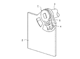
この発明の実施の形態1では、2つのチルトヒンジからなるヒンジ機構を、車両天井に設置されたモニタを開閉させて収納ケースから出し入れするために用いる場合を例に説明する。図1は、この発明の実施の形態1に係るヒンジ機構を示す斜視図、図2はヒンジ機構によるモニタ11の動作を示し、モニタ11を120度開いた状態の斜視図である。
図1に示すように、チルトヒンジ1は、回転中心軸Xを中心軸としてモニタ11を取り付けるモニタ取付部材10を回転させる。
図1および図2に示す回転中心軸Xは同一であり、モニタ取付部材10に取り付けられたモニタ11の開閉を2つのチルトヒンジ1によって行う。図2に示すように、モニタ11は、通常、収納ケース12内に収納されている。収納ケース12上に設けられたボタン13が押されると、ボタン13に連動してロックが外れ、モニタ11が自重で開方向へ回転する。その後、ユーザが手動により回転中心軸Xを中心にモニタ11を開閉させると、チルトヒンジ1がクリック作用によってモニタ11を所定の回転角度位置に保持する。Hereinafter, in order to explain the present invention in more detail, modes for carrying out the present invention will be described with reference to the accompanying drawings.
Embodiment 1 FIG.
In the first embodiment of the present invention, a case where a hinge mechanism including two tilt hinges is used to open and close a monitor installed on a vehicle ceiling and put it in and out of a storage case will be described as an example. FIG. 1 is a perspective view showing a hinge mechanism according to Embodiment 1 of the present invention, and FIG. 2 is a perspective view showing the operation of the
As shown in FIG. 1, the tilt hinge 1 rotates a
The rotation center axis X shown in FIGS. 1 and 2 is the same, and the two tilt hinges 1 open and close the
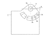
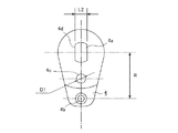
次に、この発明の実施の形態に係るチルトヒンジ1を説明する。図3はチルトヒンジ1の構成を示す斜視図、図4はチルトヒンジ1の構成を示す分解斜視図、図5はチルトヒンジ1のベース2の構成を示す正面図である。図6はチルトヒンジ1の回転シャフト3の構成を示し、図6(a)は正面図、図6(b)は側面図である。図7はチルトヒンジ1の板バネ4の構成を示す正面図、図8はチルトヒンジ1のプレート5の構成を示す正面図である。
Next, the tilt hinge 1 according to the embodiment of the present invention will be described. 3 is a perspective view showing the configuration of the tilt hinge 1, FIG. 4 is an exploded perspective view showing the configuration of the tilt hinge 1, and FIG. 5 is a front view showing the configuration of the
チルトヒンジ1は、収納ケース12に固定されるベース2、回転中心軸Xを中心軸としてベース2に対して回転可能な回転シャフト3、回転シャフト3と一体に回転する板バネ4およびプレート5から構成される。
板厚tのベース2には、回転シャフト3を挿入するための回転軸穴2aが穿設されている。また、回転中心軸Xを中心とする半径Rの円周上に、複数のクリック用凹部2bが所定の間隔をあけて凹設されている。The tilt hinge 1 includes a
A
回転シャフト3には、ベース2の回転軸穴2aの穴径よりも大径のフランジ3aと、回転軸穴2aの穴径よりもはめあい程度小さい軸径かつベース2の板厚tより若干長い円形部3bと、円形部3bの端部に当該円形部3bよりも小さい軸径かつ一対のフラット面3dが左右対称に形成されたDカット部3cとが設けられている。
The rotating shaft 3 includes a
板バネ4およびプレート5には、回転シャフト3のDカット部3cを挿入するための挿入穴4aおよび挿入穴5aが穿設されている。挿入穴4aにはフラット面3dに対応するストレート部4dが一対設けられている。挿入穴5aも同様にフラット面3dに対応するストレート部5dが一対設けられている。これら挿入穴4a,5aは、Dカット部3cの断面よりもはめあい程度大きい面積の穴となっている。即ち、このDカット部3cのフラット面間の幅をL1とすると、幅L1と挿入穴4a,5aのストレート部4d,5d間の穴幅L2には、はめあい程度の隙間が存在する。
The
板バネ4の、ベース2のクリック用凹部2bに相当する位置(挿入穴4aの中心から距離R離れた位置)には、このクリック用凹部2bに嵌り込んでクリック作用を生じさせるためのクリック用凸部4bが設けられている。また、板バネ4には、径D1の位置決め凸部4cがプレート5側に突出するように形成されている。
A click for fitting the
プレート5には、板バネ4の位置決め凸部4cの径D1よりもはめあい程度大きい穴幅L3の係合穴5bが穿設されている。チルトヒンジ1を組み立てた状態でこの係合穴5bに位置決め凸部4cが嵌り込む。
An
チルトヒンジ1の組み立て時、回転シャフト3の円形部3bにベース2の回転軸穴2aが挿入され、Dカット部3cに板バネ4の挿入穴4aおよびプレート5の挿入穴5aがそれぞれ挿入される。そして、回転シャフト3とプレート5とはカシメにより固着される。ベース2に対して回転シャフト3が回転すると、回転シャフト3と一体に板バネ4が回転してクリック用凸部4bがベース2上を摺動する。このとき、クリック用凸部4bがクリック用凹部2bに嵌り込んだり抜け出したりしてクリック作用が生じる。モニタ11は、クリック用凹部2bとクリック用凸部4bとが嵌り込むことにより、所定の回転角度位置に保持される。
When the tilt hinge 1 is assembled, the
ベース2に対して回転シャフト3が回転すると、カシメ固着されたプレート5は回転シャフト3と一体に回転する。一方、板バネ4は、回転シャフト3のDカット部3cに嵌合して回転シャフト3と一体に回転するが、幅L1と穴幅L2の隙間があるために若干のガタが生じる。この回転ガタを少なくするために、位置決め凸部4cと係合穴5bを設ける。以下、板バネ4の回転ガタについて説明する。尚、回転中心は動かないものとして説明する。
When the rotating shaft 3 rotates with respect to the
図9は、この発明の実施の形態1に係るチルトヒンジ1において、回転シャフト3に対する板バネ4とプレート5の位置を示す正面図であり、図9(a)は回転シャフト3、板バネ4およびプレート5の位置関係を示し、図9(b)では板バネ4の回転方向のガタを示し、図9(c)は位置決め凸部4cおよび係合穴5bを設けなかった場合に発生する板バネ4の回転方向のガタを示す。
FIG. 9 is a front view showing the positions of the
図9において、回転シャフト3のDカット部3cと板バネ4のストレート部4d(およびプレート5のストレート部5d)との間の隙間量A(=L2−L1)と、プレート5の係合穴5bと板バネ4の位置決め凸部4cとの間の隙間量B(=D−L3)とは同じとする。このとき、回転中心軸Xから遠い係合穴5bと位置決め凸部4cの隙間量Bによる板バネ4の傾きθ1は、回転中心軸Xに近いDカット部3cとストレート部4dの隙間量Aによる傾きθ2より小さくなる。よって、位置決め凸部4cと係合穴5bとを係合させることにより、板バネ4の回転方向のガタを少なくすることができる。この結果、板バネ4のクリック用凸部4bとクリック用凹部2bとの衝突音を抑制することが可能となる。また、クリック用凹部2bとクリック用凸部4bとが嵌り込んで保持しているモニタ11のがたつきも少なくなる。
In FIG. 9, the gap amount A (= L2−L1) between the D-cut
以上のように、実施の形態1によれば、クリック作用を有するチルトヒンジ1を、モニタ11開閉の回転軸となる回転シャフト3と、回転シャフト3を回転可能に軸支するベース2と、回転シャフト3の端部にカシメ固着されて一体で回転すると共に、係合穴5bを設けたプレート5と、回転シャフト3のDカット部3cに挿入され、且つベース2とプレート5との間に挟まれ、プレート5の係合穴5bに係合して回転シャフト3およびプレート5と一体で回転するための位置決め用凸部4cを設けた板バネ4とで構成した。そのため、回転シャフト3と板バネ4の嵌合部分には、はめあい程度のガタが生じているが、回転シャフト3にカシメ固着されたプレート5の係合穴5bと板バネ4の位置決め凸部4cが係合することで回転方向のガタが少なくなり、板バネ4の衝突音を抑制することが可能となる。
As described above, according to the first embodiment, the tilt hinge 1 having a click action is provided with the rotary shaft 3 serving as the rotation shaft for opening and closing the
実施の形態2.
図10は、この発明の実施の形態2に係るチルトヒンジ1の板バネ4の構成を示し、図10(a)は正面図、図10(b)は断面図である。図に示すように、板バネ4の位置決め凸部4cの形状は、先端径D2が基端径D3より小さいテーパ状に形成されている。また、図8に示したプレート5の係合穴5bの穴幅L3を、D2<L3<D3の関係となるように形成する。これにより、回転シャフト3にカシメ固着されたプレート5の係合穴5bが位置決め凸部4cのテーパ面の途中に掛止される。そのため、板バネ4とプレート5とのガタがなくなり、クリック作用時の板バネ4の衝突音が小さくなる。
10A and 10B show the configuration of the
以上のように、実施の形態2によれば、位置決め用凸部4cは、先端に向かって縮径するテーパ状の外周面を有し、当該外周面の途中でプレート5の係合穴5bを掛止するように構成した。そのため、板バネ4とプレート5とのガタがなくなり、クリック作用時の板バネ4のガタにより発生する衝突音を抑制することが可能となる。
As described above, according to the second embodiment, the positioning
実施の形態3.
図11は、この発明の実施の形態3に係るチルトヒンジ1の板バネ4とプレート5の状態を示し、図11(a)は板バネ4がたわんでいない状態の断面図、図11(b)は板バネ4がたわんだ状態の断面図である。図11では板バネ4とプレート5のみを示し、ベース2および回転シャフト3は図示を省略している。なお、図11(a)の板バネ4がたわんでいない状態とは、クリック作用時に、不図示のクリック用凸部4bがクリック用凹部2bに嵌り込んだ状態である。図11(b)の板バネ4がたわんだ状態とは、不図示のクリック用凸部4bがベース2上に乗り上げて摺動しているときの状態である。Embodiment 3 FIG.
FIG. 11 shows the state of the
本実施の形態では、プレート5の係合穴5bを、回転半径方向に長い略菱形穴にする。これにより、板バネ4がたわまないクリック作用時には、図11(a)に示すように板バネ4の位置決め凸部4cとプレート5の係合穴5bとの間の回転半径方向に若干の隙間が生じて当接せず、板バネ4がたわむ摺動時には、図11(b)に示すように位置決め凸部4cの外周面と係合穴5bの内周面とが当接する。
In the present embodiment, the
図12は、この発明の実施の形態3に係るチルトヒンジ1の板バネ4のたわみ量とバネ力との関係を示すグラフである。図12において、横軸は板バネ4のたわみ量を示し、縦軸は板バネ4のバネ力を示す。グラフに示す「当接」点を境にして、図11(a)に示す係合穴5bと位置決め凸部4cとが当接するまでと、図11(b)に示す当接した後とでは、板バネ4のたわみによる反力(バネ定数)が変化する。そのため、板バネ4がベース2上を摺動しているとき、即ち板バネ4がたわんで位置決め凸部4cと係合穴5bとが当接している状態のときには、大きなたわみを必要とせずに高いバネ圧が確保でき、クリック作用位置からクリック作用位置に移るための高いフリクショントルクを出すことが可能となる。従ってチルトヒンジ1の操作力を上げることができる。
FIG. 12 is a graph showing the relationship between the amount of deflection of the
以上のように、実施の形態3によれば、位置決め用凸部4cは、板バネ4がたわんだ状態のときにプレート5の係合穴5bの内周面に当接するように構成した。そのため、板バネ4のたわみによる反力(バネ定数)を当接前後で変化させることができ、チルトヒンジ1の操作力を上げることができる。
As described above, according to the third embodiment, the positioning
なお、図示例では、回転軸を中心とした、ベース2の円周上にクリック用凹部2bを設け、板バネ4にクリック用凹部2bに嵌り込むクリック用凸部4bを設けた構成であるが、上記とは反対に、ベース2にクリック用凸部を、板バネ4にクリック用凹部を設けても同一の作用効果が得られる。また、上記ではプレート5をシャフト3にカシメ固着したが、ねじ止め、接着等によって固着してもよい。
In the illustrated example, the
この発明に係るチルトヒンジは、板バネの回転方向のガタを少なくでき、衝突音の発生を防ぐことができるため、モニタを車両天井に開閉可能に連結し、複数の角度で保持するクリック作用を有するチルトヒンジ等に用いるのに適している。 The tilt hinge according to the present invention can reduce backlash in the rotational direction of the leaf spring and can prevent the occurrence of a collision sound. Therefore, the tilt hinge has a click action for connecting the monitor to the vehicle ceiling so as to be opened and closed and holding the monitor at a plurality of angles. Suitable for use in tilt hinges and the like.
Claims (2)
前記シャフトを回転自在に軸支すると共に、前記回転軸を中心とした円周上にクリック用凹凸部の一方を有するベースと、
前記シャフトの端部に取り付けて一体で回転するプレートと、
前記ベースと前記プレートとの間に位置して前記シャフトに嵌合して回転し、前記ベースに設けられた前記クリック用凹凸部の一方に嵌り込んで前記開閉体を所定の回転角度位置に保持するクリック用凹凸部の他方を有する板バネとを備え、
前記プレートは係合穴を有し、
前記板バネは前記プレートの係合穴に係合する位置決め用凸部を有して、前記シャフトおよび前記プレートと一体で回転し、
前記位置決め用凸部は、前記板バネがたわんだ状態のときに前記プレートの係合穴の内周面に当接する
ことを特徴とするチルトヒンジ。 A shaft connected to the opening and closing body and serving as a rotation axis for opening and closing;
A base that rotatably supports the shaft and has one of the click irregularities on the circumference around the rotation axis;
A plate that attaches to the end of the shaft and rotates integrally;
Positioned between the base and the plate, fitted into the shaft and rotated, and fitted into one of the click irregularities provided on the base to hold the opening / closing body at a predetermined rotational angle position. A leaf spring having the other of the click irregularities to perform,
The plate has an engagement hole;
The leaf spring has a positioning convex portion that engages with an engagement hole of the plate, and rotates integrally with the shaft and the plate .
The tilting hinge according to claim 1, wherein the positioning convex portion abuts against an inner peripheral surface of the engagement hole of the plate when the leaf spring is bent .
Priority Applications (1)
| Application Number | Priority Date | Filing Date | Title |
|---|---|---|---|
| JP2010543763A JP5236014B2 (en) | 2008-12-25 | 2009-09-25 | Tilt hinge |
Applications Claiming Priority (4)
| Application Number | Priority Date | Filing Date | Title |
|---|---|---|---|
| JP2008330500 | 2008-12-25 | ||
| JP2008330500 | 2008-12-25 | ||
| PCT/JP2009/004858 WO2010073440A1 (en) | 2008-12-25 | 2009-09-25 | Tilt hinge |
| JP2010543763A JP5236014B2 (en) | 2008-12-25 | 2009-09-25 | Tilt hinge |
Publications (2)
| Publication Number | Publication Date |
|---|---|
| JPWO2010073440A1 JPWO2010073440A1 (en) | 2012-05-31 |
| JP5236014B2 true JP5236014B2 (en) | 2013-07-17 |
Family
ID=42287105
Family Applications (1)
| Application Number | Title | Priority Date | Filing Date |
|---|---|---|---|
| JP2010543763A Active JP5236014B2 (en) | 2008-12-25 | 2009-09-25 | Tilt hinge |
Country Status (5)
| Country | Link |
|---|---|
| US (1) | US8429796B2 (en) |
| JP (1) | JP5236014B2 (en) |
| CN (1) | CN102216628B (en) |
| DE (1) | DE112009002446B4 (en) |
| WO (1) | WO2010073440A1 (en) |
Cited By (1)
| Publication number | Priority date | Publication date | Assignee | Title |
|---|---|---|---|---|
| WO2016157529A1 (en) * | 2015-04-03 | 2016-10-06 | 三菱電機株式会社 | Hinge mechanism and electronic device provided with same |
Families Citing this family (8)
| Publication number | Priority date | Publication date | Assignee | Title |
|---|---|---|---|---|
| US7934292B2 (en) * | 2007-01-04 | 2011-05-03 | Apple Inc. | Hinge mechanism |
| WO2010092640A1 (en) * | 2009-02-10 | 2010-08-19 | 三菱電機株式会社 | Hinge mechanism |
| JP5345219B2 (en) * | 2009-08-28 | 2013-11-20 | 三菱電機株式会社 | Hinge mechanism |
| JP5465327B2 (en) * | 2010-06-07 | 2014-04-09 | 三菱電機株式会社 | Hinge mechanism and monitor opening / closing mechanism |
| US20140047672A1 (en) * | 2011-02-17 | 2014-02-20 | Makoto Saito | Hinge device |
| US9428947B2 (en) * | 2012-12-04 | 2016-08-30 | Mitsubishi Electric Corporation | Hinge mechanism and panel apparatus |
| US9696754B2 (en) * | 2014-03-26 | 2017-07-04 | Intel Corporation | Hinge having multiple degrees of freedom |
| EP3183761A4 (en) | 2014-08-21 | 2018-04-25 | Dow Global Technologies LLC | Polymeric charge transfer layer and organic electronic device containing the same |
Citations (2)
| Publication number | Priority date | Publication date | Assignee | Title |
|---|---|---|---|---|
| JPH03107514U (en) * | 1990-02-22 | 1991-11-06 | ||
| JP2006105275A (en) * | 2004-10-05 | 2006-04-20 | Nhk Spring Co Ltd | Hinge device |
Family Cites Families (10)
| Publication number | Priority date | Publication date | Assignee | Title |
|---|---|---|---|---|
| JP2000055031A (en) | 1998-08-11 | 2000-02-22 | Sanko:Kk | Turning mounting mechanism |
| JP2004197862A (en) * | 2002-12-19 | 2004-07-15 | Strawberry Corporation | Hinge device and electronic apparatus using the same |
| JP4113092B2 (en) * | 2003-10-24 | 2008-07-02 | 三菱製鋼株式会社 | Biaxial hinge rotation mechanism and mobile phone equipped with the same |
| WO2007102252A1 (en) * | 2006-03-09 | 2007-09-13 | Mitsubishi Electric Corporation | Mechanism for opening and closing monitor |
| JP4428667B2 (en) | 2007-02-09 | 2010-03-10 | 三菱製鋼株式会社 | Cam type hinge mechanism |
| US7975350B2 (en) * | 2007-05-28 | 2011-07-12 | Mitsubishi Electric Corporation | Monitor hinge device |
| JP5430575B2 (en) * | 2008-09-05 | 2014-03-05 | 三菱電機株式会社 | 2-axis hinge mechanism |
| WO2010073436A1 (en) * | 2008-12-26 | 2010-07-01 | 三菱電機株式会社 | Fpc fixing structure for two-axis hinge mechanism |
| WO2010092640A1 (en) * | 2009-02-10 | 2010-08-19 | 三菱電機株式会社 | Hinge mechanism |
| JP5345219B2 (en) * | 2009-08-28 | 2013-11-20 | 三菱電機株式会社 | Hinge mechanism |
-
2009
- 2009-09-25 CN CN2009801467653A patent/CN102216628B/en not_active Expired - Fee Related
- 2009-09-25 JP JP2010543763A patent/JP5236014B2/en active Active
- 2009-09-25 US US13/060,378 patent/US8429796B2/en not_active Expired - Fee Related
- 2009-09-25 WO PCT/JP2009/004858 patent/WO2010073440A1/en active Application Filing
- 2009-09-25 DE DE112009002446T patent/DE112009002446B4/en not_active Expired - Fee Related
Patent Citations (2)
| Publication number | Priority date | Publication date | Assignee | Title |
|---|---|---|---|---|
| JPH03107514U (en) * | 1990-02-22 | 1991-11-06 | ||
| JP2006105275A (en) * | 2004-10-05 | 2006-04-20 | Nhk Spring Co Ltd | Hinge device |
Cited By (3)
| Publication number | Priority date | Publication date | Assignee | Title |
|---|---|---|---|---|
| WO2016157529A1 (en) * | 2015-04-03 | 2016-10-06 | 三菱電機株式会社 | Hinge mechanism and electronic device provided with same |
| JPWO2016157529A1 (en) * | 2015-04-03 | 2017-06-29 | 三菱電機株式会社 | Hinge mechanism and electronic apparatus equipped with the same |
| US10072700B2 (en) | 2015-04-03 | 2018-09-11 | Mitsubishi Electric Corporation | Hinge mechanism and electronic device provided with the same |
Also Published As
| Publication number | Publication date |
|---|---|
| CN102216628A (en) | 2011-10-12 |
| US20110154616A1 (en) | 2011-06-30 |
| CN102216628B (en) | 2013-11-27 |
| WO2010073440A1 (en) | 2010-07-01 |
| DE112009002446B4 (en) | 2013-04-04 |
| DE112009002446T5 (en) | 2012-08-09 |
| US8429796B2 (en) | 2013-04-30 |
| JPWO2010073440A1 (en) | 2012-05-31 |
Similar Documents
| Publication | Publication Date | Title |
|---|---|---|
| JP5236014B2 (en) | Tilt hinge | |
| JP5345219B2 (en) | Hinge mechanism | |
| JP4199230B2 (en) | Hinge structure of vehicle glove box | |
| JP4565698B2 (en) | Folding handle | |
| JP4730174B2 (en) | HINGE DEVICE AND DEVICE USING HINGE DEVICE | |
| JP5465327B2 (en) | Hinge mechanism and monitor opening / closing mechanism | |
| JP2008223247A (en) | Door hinge | |
| JP5050733B2 (en) | Locking device | |
| WO2004059182A1 (en) | Hinge device with temporary angle-setting function | |
| JP5135957B2 (en) | HINGE DEVICE AND DEVICE HAVING THE HINGE DEVICE | |
| JP3848021B2 (en) | Damper device and Western-style toilet using the device | |
| JP2006168402A (en) | Display device | |
| JP2007091002A (en) | Storage container | |
| JP5266231B2 (en) | Folding equipment | |
| JP2006257659A (en) | Hinge | |
| JP2007085469A (en) | Hinges mechanism | |
| JP2007218410A (en) | Folding equipment | |
| JP5598776B2 (en) | Hinge device | |
| JP4714168B2 (en) | Door handle device | |
| JP2002139018A (en) | Damper hinge | |
| JP2013002149A (en) | Flip-up handrail | |
| JP4764722B2 (en) | Keyhole cover structure of cylinder lock | |
| JP5797473B2 (en) | Flip-up handrail | |
| JP6879721B2 (en) | Door catch | |
| JP2002235725A (en) | Connection ring |
Legal Events
| Date | Code | Title | Description |
|---|---|---|---|
| A131 | Notification of reasons for refusal |
Free format text: JAPANESE INTERMEDIATE CODE: A131 Effective date: 20121204 |
|
| A521 | Request for written amendment filed |
Free format text: JAPANESE INTERMEDIATE CODE: A523 Effective date: 20130121 |
|
| TRDD | Decision of grant or rejection written | ||
| A01 | Written decision to grant a patent or to grant a registration (utility model) |
Free format text: JAPANESE INTERMEDIATE CODE: A01 Effective date: 20130226 |
|
| A61 | First payment of annual fees (during grant procedure) |
Free format text: JAPANESE INTERMEDIATE CODE: A61 Effective date: 20130326 |
|
| R150 | Certificate of patent or registration of utility model |
Free format text: JAPANESE INTERMEDIATE CODE: R150 Ref document number: 5236014 Country of ref document: JP Free format text: JAPANESE INTERMEDIATE CODE: R150 |
|
| FPAY | Renewal fee payment (event date is renewal date of database) |
Free format text: PAYMENT UNTIL: 20160405 Year of fee payment: 3 |
|
| R250 | Receipt of annual fees |
Free format text: JAPANESE INTERMEDIATE CODE: R250 |
|
| R250 | Receipt of annual fees |
Free format text: JAPANESE INTERMEDIATE CODE: R250 |
|
| R250 | Receipt of annual fees |
Free format text: JAPANESE INTERMEDIATE CODE: R250 |
|
| R250 | Receipt of annual fees |
Free format text: JAPANESE INTERMEDIATE CODE: R250 |
|
| R250 | Receipt of annual fees |
Free format text: JAPANESE INTERMEDIATE CODE: R250 |
|
| R250 | Receipt of annual fees |
Free format text: JAPANESE INTERMEDIATE CODE: R250 |
|
| R250 | Receipt of annual fees |
Free format text: JAPANESE INTERMEDIATE CODE: R250 |
|
| R250 | Receipt of annual fees |
Free format text: JAPANESE INTERMEDIATE CODE: R250 |