JP5231908B2 - Diesel engine exhaust gas recirculation system - Google Patents
Diesel engine exhaust gas recirculation system Download PDFInfo
- Publication number
- JP5231908B2 JP5231908B2 JP2008232534A JP2008232534A JP5231908B2 JP 5231908 B2 JP5231908 B2 JP 5231908B2 JP 2008232534 A JP2008232534 A JP 2008232534A JP 2008232534 A JP2008232534 A JP 2008232534A JP 5231908 B2 JP5231908 B2 JP 5231908B2
- Authority
- JP
- Japan
- Prior art keywords
- egr
- passage
- temperature
- gas
- intake
- Prior art date
- Legal status (The legal status is an assumption and is not a legal conclusion. Google has not performed a legal analysis and makes no representation as to the accuracy of the status listed.)
- Expired - Fee Related
Links
Images
Classifications
-
- Y—GENERAL TAGGING OF NEW TECHNOLOGICAL DEVELOPMENTS; GENERAL TAGGING OF CROSS-SECTIONAL TECHNOLOGIES SPANNING OVER SEVERAL SECTIONS OF THE IPC; TECHNICAL SUBJECTS COVERED BY FORMER USPC CROSS-REFERENCE ART COLLECTIONS [XRACs] AND DIGESTS
- Y02—TECHNOLOGIES OR APPLICATIONS FOR MITIGATION OR ADAPTATION AGAINST CLIMATE CHANGE
- Y02T—CLIMATE CHANGE MITIGATION TECHNOLOGIES RELATED TO TRANSPORTATION
- Y02T10/00—Road transport of goods or passengers
- Y02T10/10—Internal combustion engine [ICE] based vehicles
- Y02T10/12—Improving ICE efficiencies
Landscapes
- Output Control And Ontrol Of Special Type Engine (AREA)
- Exhaust-Gas Circulating Devices (AREA)
Description
本発明は、排気通路内の排気ガスの一部を吸気通路に還流するディーゼルエンジンの排気ガス再循環装置に関する。 The present invention relates to an exhaust gas recirculation device for a diesel engine that recirculates a part of exhaust gas in an exhaust passage to an intake passage.
従来より、ディーゼルエンジンには、NOxの排出を低減することを目的として、排気ガス再循環(EGR:Exhaust Gas Recirculation)装置が設けられている。EGR装置は、排気通路内の排気ガスの一部をEGRガスとして吸気通路に還流させることにより、吸気中のCO2等の不活性ガス成分を増加させる。これにより、EGR装置は、エンジンの燃焼温度を低下させてNOxの排出量を低下させる。ここで、吸気中に占めるEGRガスの割合(EGR率)が所定未満である場合において、排気ガス中におけるNOxと煤(SOOT)の発生量はトレードオフの関係にあり、SOOTの発生量は、EGR率が高くなるほど増加する。これは、エンジン筒内の酸素濃度が低下し、燃料の過濃領域が増加すると共に燃焼中のSOOTの酸化反応が緩慢となるためであると考えられる。その一方で、EGR率を所定以上まで増加させると(例えば、EGR率50%以上の大量EGRを行うと)、燃焼温度がSOOT生成温度以下の低温燃焼を実現することができ、NOxとSOOTの発生を同時に低減させることができる。 Conventionally, a diesel engine, for the purpose of reducing emissions of NO x, exhaust gas recirculation (EGR: Exhaust Gas Recirculation) device is provided. The EGR device increases an inert gas component such as CO 2 in the intake air by recirculating a part of the exhaust gas in the exhaust passage to the intake passage as EGR gas. Accordingly, EGR device reduces the emissions of the NO x by reducing the combustion temperature of the engine. Here, in the case where the ratio of the EGR gas occupying the intake (EGR rate) is less than the predetermined, the amount of the NO x and soot in the exhaust gas (SOOT) are in a trade-off relationship, the amount of SOOT is , It increases as the EGR rate increases. This is presumably because the oxygen concentration in the engine cylinder decreases, the fuel rich region increases, and the oxidation reaction of SOOT during combustion becomes slow. On the other hand, when the EGR rate is increased to a predetermined value or more (for example, when large-scale EGR with an EGR rate of 50% or more is performed), low-temperature combustion with a combustion temperature equal to or lower than the SOOT generation temperature can be realized, and NO x and SOOT Can be reduced at the same time.
ところで、過給機付きのエンジンに用いられるEGR装置としては、コンプレッサの下流側にEGRガスを還流させる高圧式のEGR装置が多く採用されている。 By the way, as an EGR device used for an engine with a supercharger, a high-pressure EGR device that recirculates EGR gas downstream of a compressor is often used.
しかしながら、高圧式のEGR装置は、コンプレッサの下流側にEGRガスを還流させる構成であるため、吸気圧よりも排気圧が十分に大きい低負荷時においては大量EGRを実現可能であるが、過給圧を増加させる中・高負荷時においては大量EGRを実現することが困難であった。 However, since the high-pressure EGR device is configured to recirculate EGR gas downstream of the compressor, a large amount of EGR can be achieved at low loads when the exhaust pressure is sufficiently higher than the intake pressure. It was difficult to achieve a large amount of EGR at medium and high loads when the pressure was increased.
そこで、近年では、タービンの下流側でディーゼルパティキュレートフィルタ(DPF:Diesel Particulate Filter)を通過後の排気ガスの一部をコンプレッサの上流側にEGRガスとして還流させる低圧式のEGR装置が提案されている(例えば、特許文献1参照)。この種の低圧EGR装置は、コンプレッサの上流側にEGRガスを導入するため、過給圧が増加するエンジンの中・高負荷時においても十分なEGRガスを還流させることができる。また、DPF通過後のガスはSOOTが除去され、EGRガスをクリーンな状態でエンジン内に導入することができるため、エンジンから排出されるSOOTの低減にも繋がる。
しかしながら、低圧式のEGR装置によって大量EGRを実現可能な負荷領域を拡大することができたとしても、ある一定の負荷以上の領域においては、燃料噴射量を増加させても必要なトルクを発生できないという新たな問題が生じる。これは、大量EGRによって酸素濃度が低下している状況下で燃料噴射量を増加させると、燃料の拡散が緩慢となり、燃料と空気の混合が不十分となることに起因する。そして、目標トルクを発生させることができない場合、エンジンの運転状態を、大量EGRによる低温燃焼の状態から、EGRガスの導入を行わない通常のディーゼル燃焼に移行しなければならなくなる。 However, even if the load range in which a large amount of EGR can be realized by the low-pressure EGR device can be expanded, the necessary torque cannot be generated even if the fuel injection amount is increased in a region exceeding a certain load. A new problem arises. This is because when the fuel injection amount is increased in a situation where the oxygen concentration is lowered due to a large amount of EGR, the diffusion of the fuel becomes slow and the mixing of fuel and air becomes insufficient. If the target torque cannot be generated, the engine operating state must be shifted from the low-temperature combustion state with a large amount of EGR to normal diesel combustion in which no EGR gas is introduced.
従って、低圧式のEGR装置を採用した場合にも、依然として、大量EGRによる低温燃焼を適用可能な負荷領域を拡大するには限界があった。なお、吸気通路に還流させるEGRガスの流量を制限することにより(EGR率を低下させることにより)、目標トルクを発生可能な領域に拡大することも考えられるが、このような場合、上述のように、NOxと同時にSOOTの発生を低減させることが困難となり、良好な排気特性を維持することが困難となる。 Therefore, even when the low-pressure EGR device is employed, there is still a limit in expanding the load range to which low-temperature combustion by a large amount of EGR can be applied. It is conceivable to limit the flow rate of the EGR gas recirculated to the intake passage (by reducing the EGR rate) to expand the target torque to a region where it can be generated. in, it is difficult to reduce the generation of the NO x simultaneously SOOT, it is difficult to maintain good exhaust characteristics.
本発明は上記事情に鑑みてなされたもので、好適なトルク特性と排気特性とを維持しつつ、大量EGRによる低温燃焼の適用範囲を拡大することができるディーゼルエンジンの排気ガス再循環装置を提供することを目的とする。 The present invention has been made in view of the above circumstances, and provides an exhaust gas recirculation device for a diesel engine capable of expanding the application range of low-temperature combustion by mass EGR while maintaining suitable torque characteristics and exhaust characteristics. The purpose is to do.
本発明の一態様によるディーゼルエンジンの排気ガス再循環装置は、第1の気筒群或いは第2の気筒群の何れかにそれぞれ分類される複数の気筒と、前記第1の気筒群の前記各気筒に連通する第1の吸気通路部と前記第2の気筒群の前記各気筒に連通する第2の吸気通路部とに下流側が分岐する吸気通路と、前記第1の吸気通路部にコンプレッサが介装される第1の過給機と、前記第2の吸気通路部にコンプレッサが介装される第2の過給機と、ディーゼルパティキュレートフィルタよりも下流側の排気通路と前記第1の過給機のコンプレッサよりも上流側の前記第1の吸気通路部とを連通して前記排気通路内の排気ガスの一部をEGRガスとして前記第1の吸気通路部に還流させる第1のEGR通路と、前記第1の吸気通路部に対する前記第1のEGR通路の開度を調整する第1のEGR制御弁と、第1のEGRクーラと、当該第1のEGRクーラをバイパスする第1のバイパス通路に設けられた第1のヒータと、前記第1のEGRクーラと前記第1のバイパス通路との流量比を可変調整する第1の切換弁とを備え、前記第1のEGR通路を流通する前記EGRガスを冷却或いは加熱することが可能であり、前記第1のEGR通路を流通する前記EGRガスの温度調整を行う第1の調温手段と、前記ディーゼルパティキュレートフィルタよりも下流側の前記排気通路と前記第2の過給機のコンプレッサよりも上流側の前記第2の吸気通路部とを連通して前記排気通路内の排気ガスの一部をEGRガスとして前記第2の吸気通路部に還流させる第2のEGR通路と、前記第2の吸気通路部に対する前記第2のEGR通路の開度を調整する第2のEGR制御弁と、第2のEGRクーラと、当該第2のEGRクーラをバイパスする第2のバイパス通路に設けられた第2のヒータと、前記第2のEGRクーラと前記第2のバイパス通路との流量比を可変調整する第2の切換弁とを備え、前記第2のEGR通路を流通する前記EGRガスを冷却或いは加熱することが可能であり、前記第2のEGR通路を流通する前記EGRガスの温度調整を行う第2の調温手段と、前記第1のEGRクーラの直上流でのEGRガス温度と前記第1の過給機のコンプレッサの直上流での吸気温度とに基づいて前記第1のヒータと前記第1の切換弁を制御するとともに、前記第2のEGRクーラの直上流でのEGRガス温度と前記第2の過給機のコンプレッサの直上流での吸気温度とに基づいて前記第2のヒータと前記第2の切換弁を制御する制御手段と、を備え、前記制御手段は、EGRガス中の水蒸気が凝縮を開始する凝縮温度よりも所定に高い設定温度に基づいて制御を行うものであり、前記第1の過給機のコンプレッサの直上流での吸気温度が前記設定温度よりも高い場合であっても前記第1のEGRクーラの直上流でのEGRガス温度が前記設定温度以下である場合には前記第1の切換弁の制御を通じて前記第1のEGRクーラへのEGRガスの流通を遮断し、前記第2の過給機のコンプレッサの直上流での吸気温度が前記設定温度よりも高い場合であっても前記第2のEGRクーラの直上流でのEGRガス温度が前記設定温度以下である場合には前記第2の切換弁の制御を通じて前記第2のEGRクーラへのEGRガスの流通を遮断するものである。
An exhaust gas recirculation device for a diesel engine according to an aspect of the present invention includes a plurality of cylinders that are classified as either a first cylinder group or a second cylinder group, and the cylinders of the first cylinder group. A first intake passage portion communicating with the first intake passage portion and a second intake passage portion communicating with the respective cylinders of the second cylinder group, an intake passage branching downstream, and a compressor interposed in the first intake passage portion A first supercharger, a second supercharger in which a compressor is interposed in the second intake passage, an exhaust passage downstream of the diesel particulate filter, and the first supercharger. A first EGR passage that communicates with the first intake passage portion upstream of the compressor of the feeder to recirculate a part of the exhaust gas in the exhaust passage to the first intake passage portion as EGR gas. And with respect to the first intake passage portion A first EGR control valve that adjusts the opening degree of the first EGR passage, a first EGR cooler, the first heater provided in the first bypass passage bypassing the first EGR cooler, the A first switching valve that variably adjusts the flow rate ratio between the first EGR cooler and the first bypass passage is provided, and the EGR gas flowing through the first EGR passage can be cooled or heated. A first temperature control means for adjusting the temperature of the EGR gas flowing through the first EGR passage; the exhaust passage downstream of the diesel particulate filter; and the compressor of the second supercharger A second EGR passage communicating with the second intake passage portion upstream of the second intake passage to recirculate a part of the exhaust gas in the exhaust passage as EGR gas to the second intake passage portion; 2 intake A second EGR control valve for adjusting an opening degree of the second EGR passage for road section, a provided in the second bypass passage bypassing the second EGR cooler, the
本発明のディーゼルエンジンの排気ガス再循環装置によれば、好適なトルク特性と排気特性とを維持しつつ、大量EGRによる低温燃焼の適用範囲を拡大することができる。 According to the exhaust gas recirculation device for a diesel engine of the present invention, it is possible to expand the application range of low-temperature combustion with a large amount of EGR while maintaining suitable torque characteristics and exhaust characteristics.
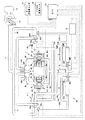
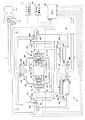
以下、図面を参照して本発明の形態を説明する。図面は本発明の一実施形態に係わり、図1は排気ガス再循環装置を備えたエンジンの概略構成図、図2はエンジンの各燃焼領域を示す図表、図3は排気ガス再循環装置を備えたエンジンの変形例を示す概略構成図である。 Hereinafter, embodiments of the present invention will be described with reference to the drawings. The drawings relate to an embodiment of the present invention, FIG. 1 is a schematic configuration diagram of an engine equipped with an exhaust gas recirculation device, FIG. 2 is a chart showing each combustion region of the engine, and FIG. 3 is equipped with an exhaust gas recirculation device. FIG.
図1に示すエンジンは、例えば、自動車等の車両に搭載される過給機付きのディーゼルエンジンであり、本実施形態では、水平対向型4気筒エンジンが示されている。このエンジン1のシリンダブロック2の左右両バンクにはシリンダヘッド3L,3Rがそれぞれ冠設されている。そして、例えば、シリンダブロック2の左バンクにはシリンダヘッド3Lとの間に#1,#3気筒2aが形成され、シリンダブロック2の右バンクにはシリンダヘッド3Rとの間に#2,#4気筒2aが形成されている。ここで、本実施形態において、これらの気筒2aは、2つの気筒群(第1,第2の気筒群)に分類されている。具体的には、#1〜#4気筒2aのうち、例えば、エンジン1の左バンクに形成される#1,#3気筒2aが第1の気筒群に分類され、エンジン1の右バンクに形成される#2,#4気筒2aが第2の気筒群に分類されている。
The engine shown in FIG. 1 is, for example, a diesel engine with a supercharger mounted on a vehicle such as an automobile. In the present embodiment, a horizontally opposed four-cylinder engine is shown.
各シリンダヘッド3L,3Rには、気筒2a毎に吸気ポート3aと排気ポート3bとが形成されている。また、各シリンダヘッド3L,3Rには、各吸、排気ポート3a,3bを開閉する吸,排気弁を動作させるための動弁機構40がそれぞれ設けられている。本実施形態において、各動弁機構40は、可変バルブタイミング機構を備えており、クランク軸に対する吸気カム軸の回転位相(変位角)を連続的に変更することにより、吸気弁の開閉タイミングをバンク毎に変更することが可能となっている。また、各シリンダヘッド3L,3Rには、燃料を筒内に直接噴射するためのインジェクタ41が気筒2a毎にそれぞれ設けられている。
In each
各吸気ポート3aは、吸気マニホルド5L,5Rを介して上流側で気筒群毎に集合され、この集合部に形成されたエアチャンバ6L,6Rを介して吸気通路7に個別に接続されている。具体的に説明すると、吸気通路7の下流側は、第1の吸気通路部7Lと第2の吸気通路部7Rとに分岐されている。そして、第1の吸気通路部7Lの下流端がエアチャンバ6Lに接続され、第2の吸気通路部7Rの下流端がエアチャンバ6Rに接続されている。
Each
第1の吸気通路部7Lには、第1のインタークーラ10Lが介装され、この第1のインタークーラ10Lの上流側に第1のターボ過給機11Lのコンプレッサ11Laが介装されている。同様に、第2の吸気通路部7Rには、第2のインタークーラ10Rが介装され、この第2のインタークーラ10Rの上流側に第2のターボ過給機11Rのコンプレッサ11Raが介装されている。
A
さらに、第1,第2の吸気通路部7L,7Rの分岐部よりも上流側において、吸気通路7には、エアクリーナ12が介装され、このエアクリーナ12の上流側に吸気チャンバ13が連通されている。
Further, an
一方、各排気ポート3bは、排気マニホルド15を介して下流側で集合され、排気通路17に接続されている。本実施形態において、排気通路17の中途は、第1,第2の気筒群に対応して第1の排気通路部17Lと第2の排気通路部17Rとに分岐された後、再度集合されている。そして、第1の排気通路部17Lには第1のターボ過給機11Lのタービン11Lbが介装され、第2の排気通路部17Rには第2のターボ過給機11Rのタービン11Rbが介装されている。
On the other hand, the
さらに、第1,第2の排気通路部17L,17Rの集合部よりも下流側において、排気通路17には、ディーゼルパティキュレートフィルタ(DPF:Diesel Particulate Filter)18が介装され、このDPF18の下流側にマフラ19が介装されている。ここで、DPF18は、周知のように、排気中のPM(パティキュレートマター:粒子状物質=主に黒煙(煤:SOOT)、SOFと称される燃え残った燃料や潤滑油の成分、サルフェートと称される軽油燃料中の硫黄分から生成される成分を含む)を捕集することで、これらの大気中への排出を抑制する。
Furthermore, a diesel particulate filter (DPF: Diesel Particulate Filter) 18 is interposed in the
このようなエンジン1の吸排気系において、吸気通路7と排気通路17との間には、排気ガス再循環装置(EGR装置)30が備えられている。本実施形態において、EGR装置30は、排気通路17内の排気ガスの一部をEGRガスとしてコンプレッサ11La,11Raの上流側に還流させる低圧式のEGR装置で構成され、このEGR装置30は第1,第2のEGR通路31L,31Rを有する。
In such an intake and exhaust system of the
第1のEGR通路31Lの一端側はDPF18よりも下流側で排気通路17に接続され、他端側はコンプレッサ11Laの上流側で第1の吸気通路部7Lに接続されている。これにより、第1のEGR通路31Lは、排気通路17と第1の吸気通路部7Lとの間を連通し、DPF18で煤等が捕集された後の排気ガスの一部を、EGRガスとしてコンプレッサ11Laの上流側に還流することが可能となっている。
One end side of the
同様に、第2のEGR通路31Rの一端側はDPF18よりも下流側で排気通路17に接続され、他端側はコンプレッサ11Laの上流側で第2の吸気通路部7Rに接続されている。これにより、第2のEGR通路31Rは、排気通路17と第2の吸気通路部7Rとの間を連通し、DPF18で煤等が捕集された後の排気ガスの一部を、EGRガスとしてコンプレッサ11Raの上流側に還流することが可能となっている。
Similarly, one end side of the
また、第1のEGR通路31Lの中途には、第1のEGR通路31Lを開閉する第1のEGR制御弁32Lが介装されている。第1のEGR制御弁32Lは、例えば、バタフライ式の弁体(図示せず)を有し、この弁体の開度がエンジン1の運転状態に応じてECU50で制御されることにより、第1のEGR通路31L内を流通するEGRガスの流量を調整する。
Further, a first
同様に、第2のEGR通路31Rの中途には、第2のEGR通路31Rを開閉する第2のEGR制御弁32Rが介装されている。第2のEGR制御弁32Rは、例えば、バタフライ式の弁体(図示せず)を有し、この弁体の開度がエンジン1の運転状態に応じてECU50で制御されることにより、第2のEGR通路31R内を流通するEGRガスの流量を調整する。
Similarly, a second
そして、EGR装置30は、気筒群に応じた2系統のEGR通路(第1,第2のEGR通路31L,31R)を有し、これら第1,第2のEGR通路31L,31Rのそれぞれに個別に介装されたEGR制御弁(第1,第2のEGR制御弁32L,32R)がエンジン制御ユニット(ECU)50を通じて開閉制御されることにより、第1,第2の気筒群をそれぞれ異なる燃焼形態で燃焼させることが可能となっている。
The
また、第1のEGR制御弁32Lよりも上流側において、第1のEGR通路31Lの中途には、第1のEGRクーラ33Lが介装されている。第1のEGRクーラ33Lは、例えば、水冷式のクーラで構成され、この第1のEGRクーラ33Lにはエンジン1の冷却水が循環される。そして、この冷却水との熱交換により、第1のEGRクーラ33Lは、第1のEGR通路31Lの内部を流通するEGRガスを冷却する。
In addition, a first EGR cooler 33L is interposed in the middle of the
また、第1のEGR通路31Lの中途には、第1のバイパス通路34Lが介装されている。この第1のバイパス通路34Lは、第1のEGRクーラ33Lと並列に介装される迂回路であり、第1のEGRクーラ33Lよりも上流側で第1のEGR通路31Lから分岐し、第1のEGRクーラ33Lよりも下流側且つ第1のEGR制御弁32Lよりも上流側で第1のEGR通路31Lに合流する。
Further, a first bypass passage 34L is interposed in the middle of the
また、第1のEGR通路31L上において、第1のEGRクーラ33Lと第1のバイパス通路34Lとの上流側の分岐部には、第1の切換弁35Lが設けられている。この第1の切換弁35Lは、例えば、三方バルブで構成され、第1のEGRクーラ33L側を流通するEGRガスと第1のバイパス通路34L側を流通するEGRガスとの流量比を調整する。すなわち、第1の切換弁35Lは、ECU50の制御により、第1のEGR通路31Lに対する第1のEGRクーラ33Lと第1のバイパス通路34Lとの連通量を切り換えることにより、第1のEGRクーラ33Lと第1のバイパス通路34Lに対するEGRガスの流量比を、1:0から0:1までの間で可変調整する。
In addition, on the
また、第1のバイパス通路34Lには、内部を流通するEGRガスを適宜昇温させるための第1のヒータ36Lが設けられている。この第1のヒータ36Lは、例えば、ECU50によって通電制御される電気抵抗式のヒータで構成され、第1のバイパス通路34Lの外周に周設されている。
The first bypass passage 34L is provided with a first heater 36L for appropriately raising the temperature of the EGR gas flowing inside. The first heater 36L is constituted by, for example, an electric resistance heater that is energized and controlled by the
本実施形態において、第1のEGRクーラ33L、第1のバイパス通路34L、第1の切換弁35L、及び、第1のヒータ36Lは、第1の調温手段を構成し、これらは、第1の切換弁35L及び第1のヒータ36LがECU50を通じて適宜作動制御されることにより、第1のEGR通路31Lを流通するEGRガスの温度調整を行う。
In the present embodiment, the
同様に、第2のEGR制御弁32Rよりも上流側において、第2のEGR通路31Rの中途には、第2のEGRクーラ33Rが介装されている。第2のEGRクーラ33Rは、例えば、水冷式のクーラで構成され、この第2のEGRクーラ33Rにはエンジン1の冷却水が循環される。そして、この冷却水との熱交換により、第2のEGRクーラ33Rは、第2のEGR通路31Rの内部を流通するEGRガスを冷却する。
Similarly, a second EGR cooler 33R is interposed in the middle of the
また、第2のEGR通路31Rの中途には、第2のバイパス通路34Rが介装されている。この第2のバイパス通路34Rは、第2のEGRクーラ33Rと並列に介装される迂回路であり、第2のEGRクーラ33Rよりも上流側で第2のEGR通路31Rから分岐し、第2のEGRクーラ33Rよりも下流側且つ第2のEGR制御弁32Rよりも上流側で第2のEGR通路31Rに合流する。
Further, a
また、第2のEGR通路31R上において、第2のEGRクーラ33Rと第2のバイパス通路34Rとの上流側の分岐部には、第2の切換弁35Rが設けられている。この第2の切換弁35Rは、例えば、三方バルブで構成され、第2のEGRクーラ33R側を流通するEGRガスと第2のバイパス通路34R側を流通するEGRガスとの流量比を調整する。すなわち、第2の切換弁35Rは、ECU50の制御により、第2のEGR通路31Rに対する第2のEGRクーラ33Rと第2のバイパス通路34Rとの連通量を切り換えることにより、第2のEGRクーラ33Rと第2のバイパス通路34Rに対するEGRガスの流量比を、1:0から0:1までの間で可変調整する。
On the
また、第2のバイパス通路34Rには、内部を流通するEGRガスを適宜昇温させるための第2のヒータ36Rが設けられている。この第2のヒータ36Rは、例えば、ECU50によって通電制御される電気抵抗式のヒータで構成され、第2のバイパス通路34Rの外周に周設されている。
The
本実施形態において、第2のEGRクーラ33R、第2のバイパス通路34R、第2の切換弁35R、及び、第2のヒータ36Rは、第2の調温手段を構成し、これらは、第2の切換弁35R及び第2のヒータ36RがECU50を通じて適宜作動制御されることにより、第2のEGR通路31Rを流通するEGRガスの温度調整を行う。
In the present embodiment, the
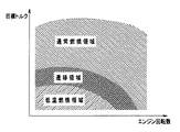
ECU50は、第1の気筒群と第2の気筒群の燃焼形態を、大量のEGRガスを還流させることにより低圧燃焼、或いは、EGRガスを還流させない通常燃焼の何れかに、それぞれ異なるタイミングで選択的に切り換えることが可能となっている。本実施形態において、ECU50は、第1,第2の気筒群の燃焼形態の切換制御を、例えば、エンジン回転数センサ51やアクセル開度センサ52等の各種センサ類からの入力信号に基づいて行う。すなわち、ECU50には、例えば、図2に示すように、エンジン回転数と、アクセル開度等から演算される目標トルクと、に基づいて各気筒群の燃焼形態を決定するためのマップが予め実験等に基づいて設定され格納されている。
The
図2のマップにおいて、低温燃焼領域は、第1の気筒群及び第2の気筒群を共に低温燃焼させた場合にも目標トルクを発生させ得る運転領域に基づいて設定されている。従って、この低温燃焼領域内にエンジン回転数と目標トルクとがあるとき、ECU50は、第1のEGR制御弁32L及び第2のEGR制御弁32Rを共に開制御する。これにより、第1の気筒群及び第2の気筒群にEGRガスが還流され、全気筒2aで低温燃焼が実現される。
In the map of FIG. 2, the low temperature combustion region is set based on an operation region in which the target torque can be generated even when both the first cylinder group and the second cylinder group are subjected to low temperature combustion. Therefore, when the engine speed and the target torque are within the low temperature combustion region, the
図2のマップにおいて、遷移領域は、第1の気筒群及び第2の気筒群を共に低温燃焼させた場合に、目標トルクに対して出力トルクが不足し始める運転領域に基づいて設定されている。従って、この遷移領域内にエンジン回転数と目標トルクとがあるとき、ECU50は、例えば、第1のEGR制御弁32Lを開制御する一方で、第2のEGR制御弁32Rを閉制御する。これにより、第1の気筒群では低温燃焼が行われる一方、第2の気筒群では、EGRガスの還流が遮断されて通常燃焼が行われる。そして、第1の気筒群で低温燃焼が行われるとともに第2の気筒群で通常燃焼が行われることにより、NOxとSOOTの発生を共に低減可能な燃焼形態を一部の気筒(#1,#3気筒)2aで維持しつつ、目標トルクに対して不足する出力トルク分が残りの気筒(#2,#4気筒)2aで補われる。
In the map of FIG. 2, the transition region is set based on an operation region where the output torque starts to become insufficient with respect to the target torque when both the first cylinder group and the second cylinder group are subjected to low temperature combustion. . Accordingly, when the engine speed and the target torque are within the transition region, the
図2のマップにおいて、通常燃焼領域は、第1の気筒群及び第2の気筒群を共に通常燃焼させなければ、目標トルクに達する出力トルクを発生させることが困難な運転領域に基づいて設定されている。従って、この通常燃焼領域にエンジン回転数と目標トルクとがあるとき、ECU50は、第1のEGR制御弁32L及び第2のEGR制御弁32Rを共に閉制御する。これにより、第1の気筒群及び第2の気筒群に対するEGRガスの還流が遮断され、全気筒2aで通常燃焼が実現される。
In the map of FIG. 2, the normal combustion region is set based on an operation region in which it is difficult to generate an output torque that reaches the target torque unless both the first cylinder group and the second cylinder group are normally combusted. ing. Accordingly, when the engine speed and the target torque are present in this normal combustion region, the
なお、ECU50は、判定した燃焼形態に応じて、動弁機構40やインジェクタ41を気筒群毎に制御し、これにより、吸気弁の開閉タイミングや燃料噴射タイミング等が最適化される。
Note that the
ここで、第1,第2のEGR通路31L,31Rには各EGRクーラ33L,33Rの直上流でのEGRガス温度(以下、クーラ前ガス温度という)TefL,TefRをそれぞれ検出するための第1,第2の温度センサ38L,38Rが設けられている。また、第1,第2の吸気通路部7L,7Rには、第1,第2のコンプレッサ11La,11Raの直上流での吸気温度(EGRガスを含む吸気温度:以下、コンプレッサ前ガス温度という)TcfL,TcfRをそれぞれ検出するための第1,第2の温度センサ39L,39Rが設けられている。
Here, in the first and
そして、ECU50は、温度センサ38L,39Lで検出された各検出温度TefL,TcfLに基づいて切換弁35L及びヒータ36Lの制御を行うことで第1のEGR通路31Lを流通するEGRガスの温度制御を行い、EGRガス中の水蒸気が凝縮水となることを抑制する。
Then, the
具体的に説明すると、第1のEGR制御弁32Lが開弁制御されて第1の気筒群にEGRガスが還流されている場合において、ECU50は、基本的には、コンプレッサ前ガス温度TcfLに基づいて第1の切換弁35L及び第1のヒータ36Lを制御する。すなわち、ECU50は、先ず、コンプレッサ前ガス温度TcfLが設定温度T2以下である場合には、第1の切換弁35Lの制御を通じて、第1のEGRクーラ33L側を流通するEGRガスの流量比を減少させる(第1のバイパス通路34L側を流通するEGRガスの流量比を増加させる)。さらに、ECU50は、第1のEGRクーラ33L側へのEGRガスの流通が遮断された場合であっても依然としてコンプレッサ前ガス温度TcfLが設定温度T2以下である場合、第1のヒータ36Lの通電制御を通じて、第1のバイパス通路34L内を流通するEGRガスの昇温制御を行う。但し、第1のEGRクーラ33L内での凝縮水の発生を防止するため、コンプレッサ前ガス温度TcfLが設定温度T2より高い場合であっても、クーラ前ガス温度TefLが設定温度T2以下である場合、ECU50は、第1のEGRクーラ33L側へのEGRガスの流通を遮断する。ここで、設定温度T2は、例えば、EGRガス中の水蒸気が凝縮を開始する温度(凝縮温度)T1を基準として設定されるもので、具体的には、凝縮温度T1(例えば、T1=100℃)よりも所定温度高い温度に設定されている。
More specifically, when the first
同様に、ECU50は、温度センサ38R,39Rで検出された各検出温度TefR,TcfRに基づいて切換弁35R及びヒータ36Rの制御を行うことで第2のEGR通路31Rを流通するEGRガスの温度制御を行い、EGRガス中の水蒸気が凝縮水となることを抑制する。
Similarly, the
具体的に説明すると、第2のEGR制御弁32Rが開弁制御されて第2の気筒群にEGRガスが還流されている場合において、ECU50は、基本的には、コンプレッサ前ガス温度TcfRに基づいて第2の切換弁35R及び第2のヒータ36Rを制御する。すなわち、ECU50は、先ず、コンプレッサ前ガス温度TcfRが設定温度T2以下である場合には、第2の切換弁35Rの制御を通じて、第2のEGRクーラ33R側を流通するEGRガスの流量比を減少させる(第2のバイパス通路34R側を流通するEGRガスの流量比を増加させる)。さらに、ECU50は、第2のEGRクーラ33R側へのEGRガスの流通が遮断された場合であっても依然としてコンプレッサ前ガス温度TcfRが設定温度T2以下である場合、第2のヒータ36Rの通電制御を通じて、第2のバイパス通路34R内を流通するEGRガスの昇温制御を行う。但し、第2のEGRクーラ33R内での凝縮水の発生を防止するため、コンプレッサ前ガス温度TcfRが設定温度T2より高い場合であっても、クーラ前ガス温度TefRが設定温度T2以下である場合、ECU50は、第2のEGRクーラ33R側へのEGRガスの流通を遮断する。
More specifically, when the second
このような実施形態によれば、#1〜#4気筒2aを第1の気筒群と第2の気筒群に分類し、吸気通路7の下流側を第1,第2の吸気通路部7L,7Rに分岐させて第1,第2の気筒群にそれぞれ連通し、第1,第2の吸気通路部7L,7Rに第1,第2のターボ過給機11L,11Rのコンプレッサ11La,11Raを介装すると共に、第1,第2のEGR制御弁32L,32Rをそれぞれ備えた第1,第2のEGR通路31L,31Rをコンプレッサ11La,11Raの上流側で第1,第2の吸気通路部7L,7Rにそれぞれ接続することにより、第1,第2の気筒群の燃焼形態をそれぞれ異なるタイミングで、低温燃焼或いは通常燃焼の何れかにそれぞれ切り換えることができる。そして、第1,第2の気筒群を共に低温燃焼させた場合に目標トルクに対して出力トルクが不足し始める運転領域において、例えば、第1の気筒群を低温燃焼させ、第2の気筒群を通常燃焼させることにより、好適なトルク特性と排気特性とを維持しつつ、大量EGRによる低温燃焼の適用範囲を拡大することができる。
According to such an embodiment, the # 1 to # 4
その際、第1,第2のEGR通路31L,31Rの中途に、第1,第2のEGRクーラ33L,33R、第1,第2のバイパス通路34L,34R、第1,第2の切換弁35L,35R、及び、第1,第2のヒータ36L,36R等からなる調温手段をそれぞれ設け、各EGR通路31L,31R内を流通するEGRガスを個別に温度調整可能とすることにより、EGRガスの温度を気筒群毎に精度よく制御することができる。すなわち、例えば、一方の気筒群に対してのみ低温燃焼を行う場合等においても、当該気筒群に還流させるEGRガスの流量等に適した専用の調温手段により、EGRガスの温度調整や管理等を容易に実現することができる。また、例えば、一方の気筒群のみを低温燃焼させた後、両気筒群を低温燃焼へと移行した場合等には、各EGR通路31L,31R等をはじめとする各部の温度等が異なる場合があるが、このような場合においても、EGRガスを気筒群毎に制御することで凝縮水の発生等を的確に抑制することができる。
At that time, in the middle of the first and
また、各気筒2aをバンク毎に第1の気筒群と第2の気筒群とに分類することにより、燃焼形態に応じて変化する動弁機構40やインジェクタ41等の制御を簡単な構成で容易に実現することができる。
Further, by classifying each
ここで、上述の実施形態においては、バンク毎に配設した第1,第2の吸気マニホルド5L,5Rにより#1〜#4気筒2aをバンク毎に第1,第2の気筒群に分類した一例について説明したが、例えば、図3に示すように、バンク間に跨る第1,第2の吸気マニホルド5A,5Bによって、異バンクの気筒2aを第1,第2の気筒群に分類することも可能である。このように構成すれば、例えば、第1,第2の気筒群で燃焼形態を異ならせた場合にも、左右バンク間の振動バランスを好適に保つことができる。
Here, in the above-described embodiment, the # 1 to # 4
なお、上述の実施形態においては、本発明の排気ガス再循環装置を水平対向型のエンジンに適用した一例について説明したが、本発明はこれに限定されるものではなく、V型エンジンや直列型の多気筒エンジンにも適用が可能であることは勿論である。 In the above-described embodiment, an example in which the exhaust gas recirculation device of the present invention is applied to a horizontally opposed engine has been described. However, the present invention is not limited to this, and a V-type engine or a series-type engine is used. Of course, the present invention can also be applied to other multi-cylinder engines.
1 … エンジン
2 … シリンダブロック
2a … 気筒
3L … シリンダヘッド
3R … シリンダヘッド
3a … 吸気ポート
3b … 排気ポート
5L … 第1の吸気マニホルド
5R … 第2の吸気マニホルド
6L … 第1のエアチャンバ
6R … 第2のエアチャンバ
7 … 吸気通路
7L … 第1の吸気通路部
7R … 第2の吸気通路部
10L … 第1のインタークーラ
10R … 第2のインタークーラ
11L … 第1のターボ過給機
11La … コンプレッサ
11Lb … タービン
11R … 第2のターボ過給機
11Ra … コンプレッサ
11Rb … タービン
12 … エアクリーナ
13 … 吸気チャンバ
15 … 排気マニホルド
17 … 排気通路
17L … 第1の排気通路部
17R … 第2の排気通路部
18 … DPF(Diesel Particulate Filter)
19 … マフラ
30 … 排気ガス再循環装置
31 … EGR通路
31C … EGR通路部
31L … 第1のEGR通路
31R … 第2のEGR通路
32L … 第1のEGR制御弁
32R … 第2のEGR制御弁
33L … 第1のEGRクーラ(第1の調温手段)
33R … 第2のEGRクーラ(第2の調温手段)
34L … 第1のバイパス通路(第1の調温手段)
34L … 第1のバイパス通路(第1の調温手段)
34R … 第2のバイパス通路(第2の調温手段)
35L … 第1の切換弁(第1の調温手段)
35R … 第2の切換弁(第2の調温手段)
36L … 第1のヒータ(第1の調温手段)
36R … 第2のヒータ(第2の調温手段)
38L … 第1の温度センサ
38R … 第2の温度センサ
39L … 第1の温度センサ
40 … 動弁機構
41 … インジェクタ
50 … エンジン制御ユニット
51 … エンジン回転数センサ
52 … アクセル開度センサ
5A … 第1の吸気マニホルド
5B … 第2の吸気マニホルド
DESCRIPTION OF
19 ...
33R ... 2nd EGR cooler (2nd temperature control means)
34L ... 1st bypass passage (1st temperature control means)
34L ... 1st bypass passage (1st temperature control means)
34R ... 2nd bypass passage (2nd temperature control means)
35L ... 1st switching valve (1st temperature control means)
35R ... 2nd switching valve (2nd temperature control means)
36L ... 1st heater (1st temperature control means)
36R ... 2nd heater (2nd temperature control means)
38L ...
Claims (1)
前記第1の気筒群の前記各気筒に連通する第1の吸気通路部と前記第2の気筒群の前記各気筒に連通する第2の吸気通路部とに下流側が分岐する吸気通路と、
前記第1の吸気通路部にコンプレッサが介装される第1の過給機と、
前記第2の吸気通路部にコンプレッサが介装される第2の過給機と、
ディーゼルパティキュレートフィルタよりも下流側の排気通路と前記第1の過給機のコンプレッサよりも上流側の前記第1の吸気通路部とを連通して前記排気通路内の排気ガスの一部をEGRガスとして前記第1の吸気通路部に還流させる第1のEGR通路と、
前記第1の吸気通路部に対する前記第1のEGR通路の開度を調整する第1のEGR制御弁と、
第1のEGRクーラと、当該第1のEGRクーラをバイパスする第1のバイパス通路に設けられた第1のヒータと、前記第1のEGRクーラと前記第1のバイパス通路との流量比を可変調整する第1の切換弁とを備え、前記第1のEGR通路を流通する前記EGRガスを冷却或いは加熱することが可能であり、前記第1のEGR通路を流通する前記EGRガスの温度調整を行う第1の調温手段と、
前記ディーゼルパティキュレートフィルタよりも下流側の前記排気通路と前記第2の過給機のコンプレッサよりも上流側の前記第2の吸気通路部とを連通して前記排気通路内の排気ガスの一部をEGRガスとして前記第2の吸気通路部に還流させる第2のEGR通路と、
前記第2の吸気通路部に対する前記第2のEGR通路の開度を調整する第2のEGR制御弁と、
第2のEGRクーラと、当該第2のEGRクーラをバイパスする第2のバイパス通路に設けられた第2のヒータと、前記第2のEGRクーラと前記第2のバイパス通路との流量比を可変調整する第2の切換弁とを備え、前記第2のEGR通路を流通する前記EGRガスを冷却或いは加熱することが可能であり、前記第2のEGR通路を流通する前記EGRガスの温度調整を行う第2の調温手段と、
前記第1のEGRクーラの直上流でのEGRガス温度と前記第1の過給機のコンプレッサの直上流での吸気温度とに基づいて前記第1のヒータと前記第1の切換弁を制御するとともに、前記第2のEGRクーラの直上流でのEGRガス温度と前記第2の過給機のコンプレッサの直上流での吸気温度とに基づいて前記第2のヒータと前記第2の切換弁を制御する制御手段と、を備え、
前記制御手段は、EGRガス中の水蒸気が凝縮を開始する凝縮温度よりも所定に高い設定温度に基づいて制御を行うものであり、前記第1の過給機のコンプレッサの直上流での吸気温度が前記設定温度よりも高い場合であっても前記第1のEGRクーラの直上流でのEGRガス温度が前記設定温度以下である場合には前記第1の切換弁の制御を通じて前記第1のEGRクーラへのEGRガスの流通を遮断し、前記第2の過給機のコンプレッサの直上流での吸気温度が前記設定温度よりも高い場合であっても前記第2のEGRクーラの直上流でのEGRガス温度が前記設定温度以下である場合には前記第2の切換弁の制御を通じて前記第2のEGRクーラへのEGRガスの流通を遮断することを特徴とするディーゼルエンジンの排気ガス再循環装置。 A plurality of cylinders each classified as either a first cylinder group or a second cylinder group;
An intake passage branched downstream from a first intake passage portion communicating with each cylinder of the first cylinder group and a second intake passage portion communicating with each cylinder of the second cylinder group;
A first supercharger in which a compressor is interposed in the first intake passage portion;
A second supercharger in which a compressor is interposed in the second intake passage portion;
A portion of the exhaust gas in the exhaust passage is EGRed by connecting the exhaust passage downstream of the diesel particulate filter and the first intake passage upstream of the compressor of the first supercharger. A first EGR passage that recirculates as gas to the first intake passage portion;
A first EGR control valve that adjusts an opening of the first EGR passage relative to the first intake passage portion;
The flow rate ratio between the first EGR cooler, the first heater provided in the first bypass passage that bypasses the first EGR cooler, and the first EGR cooler and the first bypass passage is variable. A first switching valve for adjusting the EGR gas flowing through the first EGR passage, and cooling or heating the EGR gas, and adjusting the temperature of the EGR gas flowing through the first EGR passage. First temperature control means to perform;
A part of the exhaust gas in the exhaust passage by communicating the exhaust passage downstream of the diesel particulate filter and the second intake passage upstream of the compressor of the second supercharger. A second EGR passage that recirculates gas as EGR gas to the second intake passage portion;
A second EGR control valve for adjusting an opening degree of the second EGR passage relative to the second intake passage portion;
The flow rate ratio between the second EGR cooler, the second heater provided in the second bypass passage that bypasses the second EGR cooler, and the second EGR cooler and the second bypass passage is variable. A second switching valve that adjusts the temperature of the EGR gas that flows through the second EGR passage , and is capable of cooling or heating the EGR gas that flows through the second EGR passage. A second temperature control means to perform ;
The first heater and the first switching valve are controlled based on the EGR gas temperature immediately upstream of the first EGR cooler and the intake air temperature immediately upstream of the compressor of the first supercharger. And the second heater and the second switching valve based on the EGR gas temperature immediately upstream of the second EGR cooler and the intake air temperature immediately upstream of the compressor of the second supercharger. Control means for controlling,
The control means performs control based on a preset temperature that is higher than a condensation temperature at which water vapor in the EGR gas starts condensing, and an intake air temperature immediately upstream of the compressor of the first supercharger. Is higher than the set temperature, but the EGR gas temperature immediately upstream of the first EGR cooler is equal to or lower than the set temperature, the first EGR is controlled through the control of the first switching valve. Even if the intake air temperature immediately upstream of the compressor of the second supercharger is higher than the set temperature, the flow of EGR gas to the cooler is shut off. exhaust gas recirculation diesel engine EGR gas temperature is equal to or blocking the flow of EGR gas to the second EGR cooler through the control of the second switching valve when it is less than the set temperature Location.
Priority Applications (1)
| Application Number | Priority Date | Filing Date | Title |
|---|---|---|---|
| JP2008232534A JP5231908B2 (en) | 2008-09-10 | 2008-09-10 | Diesel engine exhaust gas recirculation system |
Applications Claiming Priority (1)
| Application Number | Priority Date | Filing Date | Title |
|---|---|---|---|
| JP2008232534A JP5231908B2 (en) | 2008-09-10 | 2008-09-10 | Diesel engine exhaust gas recirculation system |
Publications (2)
| Publication Number | Publication Date |
|---|---|
| JP2010065601A JP2010065601A (en) | 2010-03-25 |
| JP5231908B2 true JP5231908B2 (en) | 2013-07-10 |
Family
ID=42191391
Family Applications (1)
| Application Number | Title | Priority Date | Filing Date |
|---|---|---|---|
| JP2008232534A Expired - Fee Related JP5231908B2 (en) | 2008-09-10 | 2008-09-10 | Diesel engine exhaust gas recirculation system |
Country Status (1)
| Country | Link |
|---|---|
| JP (1) | JP5231908B2 (en) |
Families Citing this family (4)
| Publication number | Priority date | Publication date | Assignee | Title |
|---|---|---|---|---|
| WO2011101891A1 (en) * | 2010-02-17 | 2011-08-25 | トヨタ自動車株式会社 | Exhaust device of internal combustion engine |
| EP2420552B1 (en) * | 2010-08-19 | 2017-12-20 | Infineum International Limited | Use of phenothiazine derivatives in lubricating oil compositions in EGR equipped diesel engines |
| JP5918475B2 (en) * | 2011-03-29 | 2016-05-18 | 日野自動車株式会社 | EGR device |
| JP5831790B2 (en) * | 2011-08-11 | 2015-12-09 | 三菱自動車工業株式会社 | Internal combustion engine |
Family Cites Families (12)
| Publication number | Priority date | Publication date | Assignee | Title |
|---|---|---|---|---|
| JP4007651B2 (en) * | 1997-10-17 | 2007-11-14 | 株式会社日本自動車部品総合研究所 | EGR gas temperature control system for diesel engine |
| US6681171B2 (en) * | 2001-12-18 | 2004-01-20 | Detroit Diesel Corporation | Condensation control for internal combustion engines using EGR |
| JP2005076508A (en) * | 2003-08-29 | 2005-03-24 | Nissan Motor Co Ltd | Engine exhaust gas recirculation system |
| JP4392689B2 (en) * | 2004-05-25 | 2010-01-06 | 明男 石田 | Cylinder group individually controlled engine |
| JP4305295B2 (en) * | 2004-06-21 | 2009-07-29 | トヨタ自動車株式会社 | Diesel engine control device |
| JP2006177191A (en) * | 2004-12-21 | 2006-07-06 | Hino Motors Ltd | engine |
| JP2007040136A (en) * | 2005-08-02 | 2007-02-15 | Denso Corp | Exhaust gas recirculation system of internal combustion engine with supercharger |
| US7284366B2 (en) * | 2005-09-28 | 2007-10-23 | Ford Global Technologies, Llc | System and method for operating an engine having an exhaust gas recirculation system |
| JP2007315345A (en) * | 2006-05-29 | 2007-12-06 | Toyota Industries Corp | Intake structure for internal combustion chamber |
| JP2008075505A (en) * | 2006-09-20 | 2008-04-03 | Toyota Motor Corp | Control device for internal combustion engine |
| JP4779926B2 (en) * | 2006-10-25 | 2011-09-28 | トヨタ自動車株式会社 | Exhaust system for internal combustion engine |
| JP2008111388A (en) * | 2006-10-31 | 2008-05-15 | Nissan Motor Co Ltd | Exhaust gas recirculation control device |
-
2008
- 2008-09-10 JP JP2008232534A patent/JP5231908B2/en not_active Expired - Fee Related
Also Published As
| Publication number | Publication date |
|---|---|
| JP2010065601A (en) | 2010-03-25 |
Similar Documents
| Publication | Publication Date | Title |
|---|---|---|
| US7971576B2 (en) | Internal combustion engine and method for operating an internal combustion engine | |
| US9188050B2 (en) | Engine cooling system | |
| US8904787B2 (en) | Fixed rate EGR system | |
| US9038611B2 (en) | NOx feedback for combustion control | |
| JP4924229B2 (en) | EGR system for internal combustion engine | |
| US9995204B2 (en) | Method for operating an internal combustion engine with charge-air cooler | |
| US20080209889A1 (en) | Internal Combustion Engine Featuring Exhaust Gas Aftertreatment and Method For the Operation Thereof | |
| US8950384B2 (en) | Method for operating an internal combustion engine with charge-air cooler | |
| CN104471221B (en) | Method and system for an engine | |
| JP2008069722A (en) | Internal combustion engine | |
| CN105358810B (en) | Method for the internal combustion engine of motor vehicle and for running such internal combustion engine | |
| JP6406417B1 (en) | Turbocharged engine | |
| JP5231908B2 (en) | Diesel engine exhaust gas recirculation system | |
| JP2009264335A (en) | Multistage supercharging system for internal combustion engine | |
| JP2007162577A (en) | Internal turbocharged engine | |
| JP2009156090A (en) | Exhaust gas recirculation device for variable cylinder internal combustion engine | |
| JP2010223077A (en) | Internal combustion engine | |
| US11754007B2 (en) | Systems and methods for exhaust gas recirculation | |
| JP2011214552A (en) | Internal combustion engine | |
| JP2021080888A (en) | EGR device | |
| JP2009085094A (en) | Exhaust gas recirculation device for engine | |
| US20070089412A1 (en) | Method for controlling an exhaust gas recirculation system | |
| JP3711939B2 (en) | Control device for spark ignition engine | |
| JP2009250209A (en) | Exhaust gas recirculating device of internal combustion engine | |
| JP6451812B1 (en) | Engine exhaust gas recirculation control device |
Legal Events
| Date | Code | Title | Description |
|---|---|---|---|
| A621 | Written request for application examination |
Free format text: JAPANESE INTERMEDIATE CODE: A621 Effective date: 20110330 |
|
| A131 | Notification of reasons for refusal |
Free format text: JAPANESE INTERMEDIATE CODE: A131 Effective date: 20120313 |
|
| A521 | Written amendment |
Free format text: JAPANESE INTERMEDIATE CODE: A523 Effective date: 20120425 |
|
| A131 | Notification of reasons for refusal |
Free format text: JAPANESE INTERMEDIATE CODE: A131 Effective date: 20120814 |
|
| A521 | Written amendment |
Free format text: JAPANESE INTERMEDIATE CODE: A523 Effective date: 20121004 |
|
| TRDD | Decision of grant or rejection written | ||
| A01 | Written decision to grant a patent or to grant a registration (utility model) |
Free format text: JAPANESE INTERMEDIATE CODE: A01 Effective date: 20130226 |
|
| A61 | First payment of annual fees (during grant procedure) |
Free format text: JAPANESE INTERMEDIATE CODE: A61 Effective date: 20130322 |
|
| FPAY | Renewal fee payment (event date is renewal date of database) |
Free format text: PAYMENT UNTIL: 20160329 Year of fee payment: 3 |
|
| R150 | Certificate of patent or registration of utility model |
Free format text: JAPANESE INTERMEDIATE CODE: R150 |
|
| S531 | Written request for registration of change of domicile |
Free format text: JAPANESE INTERMEDIATE CODE: R313531 |
|
| R350 | Written notification of registration of transfer |
Free format text: JAPANESE INTERMEDIATE CODE: R350 |
|
| R250 | Receipt of annual fees |
Free format text: JAPANESE INTERMEDIATE CODE: R250 |
|
| LAPS | Cancellation because of no payment of annual fees |