JP5231645B2 - Beam forming vector generation method and beam forming vector generation information provision method - Google Patents
Beam forming vector generation method and beam forming vector generation information provision methodInfo
- Publication number
- JP5231645B2 JP5231645B2 JP2011522913A JP2011522913A JP5231645B2 JP 5231645 B2 JP5231645 B2 JP 5231645B2 JP 2011522913 A JP2011522913 A JP 2011522913A JP 2011522913 A JP2011522913 A JP 2011522913A JP 5231645 B2 JP5231645 B2 JP 5231645B2
- Authority
- JP
- Japan
- Prior art keywords
- precoding matrix
- base station
- terminal
- beamforming vector
- index
- Prior art date
- Legal status (The legal status is an assumption and is not a legal conclusion. Google has not performed a legal analysis and makes no representation as to the accuracy of the status listed.)
- Expired - Fee Related
Links
Images


Classifications
-
- H—ELECTRICITY
- H04—ELECTRIC COMMUNICATION TECHNIQUE
- H04B—TRANSMISSION
- H04B7/00—Radio transmission systems, i.e. using radiation field
- H04B7/02—Diversity systems; Multi-antenna system, i.e. transmission or reception using multiple antennas
- H04B7/04—Diversity systems; Multi-antenna system, i.e. transmission or reception using multiple antennas using two or more spaced independent antennas
- H04B7/06—Diversity systems; Multi-antenna system, i.e. transmission or reception using multiple antennas using two or more spaced independent antennas at the transmitting station
- H04B7/0613—Diversity systems; Multi-antenna system, i.e. transmission or reception using multiple antennas using two or more spaced independent antennas at the transmitting station using simultaneous transmission
- H04B7/0615—Diversity systems; Multi-antenna system, i.e. transmission or reception using multiple antennas using two or more spaced independent antennas at the transmitting station using simultaneous transmission of weighted versions of same signal
- H04B7/0617—Diversity systems; Multi-antenna system, i.e. transmission or reception using multiple antennas using two or more spaced independent antennas at the transmitting station using simultaneous transmission of weighted versions of same signal for beam forming
-
- H—ELECTRICITY
- H04—ELECTRIC COMMUNICATION TECHNIQUE
- H04B—TRANSMISSION
- H04B7/00—Radio transmission systems, i.e. using radiation field
- H04B7/02—Diversity systems; Multi-antenna system, i.e. transmission or reception using multiple antennas
- H04B7/04—Diversity systems; Multi-antenna system, i.e. transmission or reception using multiple antennas using two or more spaced independent antennas
- H04B7/0413—MIMO systems
- H04B7/0417—Feedback systems
-
- H—ELECTRICITY
- H04—ELECTRIC COMMUNICATION TECHNIQUE
- H04B—TRANSMISSION
- H04B7/00—Radio transmission systems, i.e. using radiation field
- H04B7/02—Diversity systems; Multi-antenna system, i.e. transmission or reception using multiple antennas
- H04B7/04—Diversity systems; Multi-antenna system, i.e. transmission or reception using multiple antennas using two or more spaced independent antennas
- H04B7/06—Diversity systems; Multi-antenna system, i.e. transmission or reception using multiple antennas using two or more spaced independent antennas at the transmitting station
- H04B7/0613—Diversity systems; Multi-antenna system, i.e. transmission or reception using multiple antennas using two or more spaced independent antennas at the transmitting station using simultaneous transmission
- H04B7/0615—Diversity systems; Multi-antenna system, i.e. transmission or reception using multiple antennas using two or more spaced independent antennas at the transmitting station using simultaneous transmission of weighted versions of same signal
- H04B7/0619—Diversity systems; Multi-antenna system, i.e. transmission or reception using multiple antennas using two or more spaced independent antennas at the transmitting station using simultaneous transmission of weighted versions of same signal using feedback from receiving side
- H04B7/0636—Feedback format
- H04B7/0639—Using selective indices, e.g. of a codebook, e.g. pre-distortion matrix index [PMI] or for beam selection
-
- Y—GENERAL TAGGING OF NEW TECHNOLOGICAL DEVELOPMENTS; GENERAL TAGGING OF CROSS-SECTIONAL TECHNOLOGIES SPANNING OVER SEVERAL SECTIONS OF THE IPC; TECHNICAL SUBJECTS COVERED BY FORMER USPC CROSS-REFERENCE ART COLLECTIONS [XRACs] AND DIGESTS
- Y02—TECHNOLOGIES OR APPLICATIONS FOR MITIGATION OR ADAPTATION AGAINST CLIMATE CHANGE
- Y02D—CLIMATE CHANGE MITIGATION TECHNOLOGIES IN INFORMATION AND COMMUNICATION TECHNOLOGIES [ICT], I.E. INFORMATION AND COMMUNICATION TECHNOLOGIES AIMING AT THE REDUCTION OF THEIR OWN ENERGY USE
- Y02D30/00—Reducing energy consumption in communication networks
- Y02D30/70—Reducing energy consumption in communication networks in wireless communication networks
Description
本発明は、ビームフォーミングベクトルを生成する方法に関する。 The present invention relates to a method for generating a beamforming vector.
MIMO(Multi Input Multi Output)通信システムは、多重入出力が可能なアンテナシステムであって、基地局と端末のアンテナを2つ以上に増やしてデータを多様な経路に伝送し、受信端でそれぞれの経路で受信された信号を検出して干渉を減少させ、それぞれの伝送速度を低めることができる技術である。 A MIMO (Multi Input Multi Output) communication system is an antenna system capable of multiple input / output, and transmits data to various paths by increasing the number of antennas of a base station and a terminal to two or more. This is a technique that can detect a signal received through a path, reduce interference, and reduce the transmission speed of each signal.
多重アンテナを使用する端末は、ビームフォーミングベクトルを用いてデータの伝送方向を制御することができる。しかしながら、このようなビームフォーミングベクトルは、隣接セル干渉を起こすことがあり、隣接セル干渉を考慮したビームフォーミングベクトルの生成方法が要求される。 A terminal using multiple antennas can control a data transmission direction using a beamforming vector. However, such a beamforming vector may cause adjacent cell interference, and a method for generating a beamforming vector in consideration of adjacent cell interference is required.
背景技術に記載された事項は、単に本発明の背景に関する理解を助けるためのものであり、当業者に公知の従来の技術と関係のない情報を含むこともある。 The matters described in the background art are merely to help understanding the background of the present invention, and may include information unrelated to conventional techniques known to those skilled in the art.
本発明が目的とする技術的課題は、隣接セル干渉を考慮したビームフォーミングベクトル生成方法およびビームフォーミングベクトル生成情報提供方法を提供することにある。 A technical problem to which the present invention is directed is to provide a beamforming vector generation method and beamforming vector generation information provision method in consideration of adjacent cell interference.
本発明の一実施形態にかかる、端末がビームフォーミングベクトルを生成する方法は、サービング基地局から第1事前コーディング行列および第2事前コーディング行列に対する情報を受信する段階;および前記第1事前コーディング行列および前記第2事前コーディング行列を線形結合してビームフォーミングベクトルを生成する段階を含み、前記第1事前コーディング行列は、前記端末から前記サービング基地局への伝送電力を最大にする事前コーディング行列であり、前記第2事前コーディング行列は、前記端末から隣接基地局への干渉電力を最小にする事前コーディング行列である。 A method for generating a beamforming vector by a terminal according to an embodiment of the present invention includes receiving information on a first precoding matrix and a second precoding matrix from a serving base station; and the first precoding matrix and Linearly combining the second precoding matrix to generate a beamforming vector, wherein the first precoding matrix is a precoding matrix that maximizes transmission power from the terminal to the serving base station; The second precoding matrix is a precoding matrix that minimizes interference power from the terminal to an adjacent base station.
本発明の一実施形態にかかる、サービング基地局から端末にビームフォーミングベクトル生成情報を提供する方法は、前記端末に事前コーディング行列の結合を指示する段階;および前記端末から第1事前コーディング行列および第2事前コーディング行列に対する情報を前記端末に伝送する段階を含み、前記第1事前コーディング行列は、前記端末から前記サービング基地局への伝送電力を最大にする事前コーディング行列であり、前記第2事前コーディング行列は、前記端末から隣接基地局への干渉電力を最小にする事前コーディング行列である。 According to an embodiment of the present invention, a method for providing beamforming vector generation information from a serving base station to a terminal instructs the terminal to combine precoding matrices; and from the terminal a first precoding matrix and Transmitting information on two precoding matrices to the terminal, wherein the first precoding matrix is a precoding matrix that maximizes transmission power from the terminal to the serving base station, and the second precoding matrix The matrix is a precoding matrix that minimizes the interference power from the terminal to the adjacent base station.
本発明の一実施形態にかかる、端末がビームフォーミングベクトルを生成する方法は、第1事前コーディング行列および第2事前コーディング行列を選択する段階;および前記第1事前コーディング行列および前記第2事前コーディング行列を線形結合してビームフォーミングベクトルを生成する段階を含み、前記第1事前コーディング行列は、前記端末とサービング基地局との間のチャンネルに対するSINRを最大にする事前コーディング行列であり、前記第2事前コーディング行列は、前記端末と隣接基地局との間のチャンネルに対するナリングのための事前コーディング行列である。 A method for generating a beamforming vector by a terminal according to an embodiment of the present invention includes selecting a first precoding matrix and a second precoding matrix; and the first precoding matrix and the second precoding matrix. Are combined to generate a beamforming vector, wherein the first precoding matrix is a precoding matrix that maximizes SINR for a channel between the terminal and a serving base station, and the second precoding matrix The coding matrix is a precoding matrix for nulling a channel between the terminal and an adjacent base station.
本発明の実施形態によれば、隣接セル干渉を考慮したビームフォーミングベクトル生成方法およびビームフォーミングベクトル生成情報提供方法を提供することができる。 According to the embodiment of the present invention, it is possible to provide a beamforming vector generation method and beamforming vector generation information provision method in consideration of adjacent cell interference.
以下、添付図面を参照して本発明の実施形態について本発明が属する技術分野で通常の知識を有する者が容易に実施することができるように詳しく説明する。しかしながら、本発明は多様な異なる形態で具現することができ、ここで説明する実施形態に限定されない。そして、図面において、本発明を明確に説明するために、説明上不要な部分は省略し、明細書全体を通して類似する部分については類似する図面符号を付した。 Hereinafter, embodiments of the present invention will be described in detail with reference to the accompanying drawings so that a person having ordinary knowledge in the technical field to which the present invention can easily carry out. However, the present invention may be embodied in a variety of different forms and is not limited to the embodiments described herein. In the drawings, in order to clearly describe the present invention, parts unnecessary for the description are omitted, and like parts are denoted by like reference numerals throughout the specification.
明細書全体において、ある部分がある構成要素を「含む」とする時、これは特に反対の記載がない限り、他の構成要素を除外するのではなく、他の構成要素をさらに含むことを意味する。 Throughout the specification, when a part “includes” a component, this means that the component does not exclude other components, but includes other components, unless specifically stated to the contrary. To do.
次に、本発明の実施形態にかかるビームフォーミングベクトル生成方法およびビームフォーミングベクトル生成情報提供方法について図面を参照して詳細に説明する。 Next, a beamforming vector generation method and a beamforming vector generation information provision method according to an embodiment of the present invention will be described in detail with reference to the drawings.
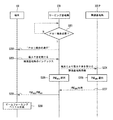
図1は、本発明の一実施形態にかかる通信システムを概念的に示した図面であり、図2は、本発明の一実施形態にかかるビームフォーミングベクトル生成方法を示したフローチャートである。 FIG. 1 conceptually illustrates a communication system according to an embodiment of the present invention, and FIG. 2 is a flowchart illustrating a beamforming vector generation method according to an embodiment of the present invention.
図1および図2を参照すれば、本発明の一実施形態にかかる通信システムは、端末100、サービング基地局200および複数の隣接基地局300_1、300_2、…、300_nを含む。
1 and 2, a communication system according to an embodiment of the present invention includes a
サービング基地局200は、端末100から受信された信号に基づいてチャンネル測定を行い、チャンネル測定に基づいて端末100が事前コーディング行列インデックス結合(Precoding Matrix index(PMI)combination、以下、「PMI結合」という)を行う必要があるか否か判断する(S201)。
The
ここで、PMI結合は、端末100がコードブック({Wj})に含まれている複数の事前コーディング行列(Precoding Matrix)のうちの一部を結合してビームフォーミングベクトルを生成することをいう。
Here, PMI combining means that
サービング基地局200は、PMI結合を行う必要があるかを判断するために干渉量を使用することができる。つまり、サービング基地局200は、干渉量が予め設定されている基準値以上である場合、端末100による干渉の影響が大きいと把握し、PMI結合を行う必要があると判断する。
The
このような干渉量として熱雑音に対する干渉量(interference over thermal、IoT)、信号対干渉雑音比率(Signal to Interference plus Noise Ratio、SINR)、キャリア対雑音比率(Carrier to interface ratio、CINR)などが使用され得る。 As such an interference amount, an interference amount against thermal noise (interference over thermal, IoT), a signal-to-interference noise ratio (Signal to Interference plus Noise Ratio, SINR), a carrier-to-noise ratio (Carrier to interface ratio, CINR), etc. are used. Can be done.
PMI結合を行う必要があると判断した場合、サービング基地局200はPMI結合の遂行を示すメッセージを端末100に伝送する(S202)。このようなメッセージとしては、マップ(MAP)管理(management)メッセージが使用され得る。
When determining that it is necessary to perform PMI coupling, the
メッセージを受信した端末100は、複数の隣接基地局300_1、300_2、…、300_nのうち、端末100による最大干渉を受ける隣接基地局を把握する。
The
端末100による最大干渉を受ける隣接基地局は、多様な方式で把握され得、例えば、受信信号強度(Received Signal Strength indication、RSSI)を用いて数式1のような方式で把握され得る。

数式1中、pは、隣接基地局300_1、300_2、…、300_nのインデックスであり、qは、サービング基地局200のインデックスであり、iは、端末100のインデックスである。RSSIp、iは、インデックスがpである隣接基地局からインデックスがiである端末への受信信号強度を示し、RSSIq、iはインデックスがqであるサービング基地局からインデックスがiである端末への受信信号強度を示し、数式1によりRSSIp、iからRSSIq、iを引いた値が最大になる隣接基地局を端末100は端末100により最大干渉を受ける隣接基地局300_Pと把握する。
In Equation 1, p is an index of adjacent base stations 300_1, 300_2,..., 300_n, q is an index of
その後、端末100は、数式1により把握された最大干渉を受ける隣接基地局300_PのインデックスPに対応する情報をサービング基地局200に伝送し(S203)、サービング基地局200は、隣接基地局300_Pに隣接基地局300_Pが端末100により最大干渉を受ける隣接基地局であることを示すメッセージを伝送する(S204)。
After that, the
その後、サービング基地局200は、端末100から受信した信号、例えば、サウンディング信号(sounding signal)を用いて端末100とサービング基地局200との間のチャンネル(HS)を測定し、数式2を用いて端末100からサービング基地局200への伝送電力を最大にする事前コーディング行列インデックス(PMIMax)を選択する(S205)。端末100とサービング基地局200との間のチャンネルに対するSINRを最大化するための行列が端末100からサービング基地局200への伝送電力を最大にする行列の一例になり得る。
Thereafter, the
このために、サービング基地局200は、コードブック({Wj})に含まれている複数の事前コーディング行列のうちで、端末100とサービング基地局200との間のチャンネル行列(HS)との積(Wj・HS)の大きさを最大にする事前コーディング行列に対するインデックスをPMIMaxとして選択する。この場合、Wj・HS行列の大きさを数式2のようにWj・HS行列のノルマ(norm)の二乗で計算することができる。
数式2中、Wjは、コードブック{Wj}に含まれている複数の事前コーディング行列のそれぞれを意味する。
In
一方、数式1に基いて端末100により最大干渉を受ける隣接基地局として決定された隣接基地局300_Pは、端末100から受信した信号、例えば、サウンディング信号を用いて端末100と隣接基地局300_Pとの間のチャンネル(HI)を測定し、数式3を用いて端末100から隣接基地局300_Pへの干渉の影響を最小にする事前コーディング行列インデックス(PMIMin)を選択する(S206)。端末100と隣接基地局300_Pとの間のチャンネルに対するナリング(nulling)のための行列を用いて端末100から隣接基地局300_Pへの干渉の影響を最小にする事前コーディング行列の一例になり得る。
On the other hand, the adjacent base station 300_P determined as the adjacent base station that receives the maximum interference by the
このために、隣接基地局300_Pは、コードブック({Wj})に含まれている複数の事前コーディング行列のうちで、端末100と隣接基地局300_Pとの間のチャンネル行列(HI)との積(Wj・HI)の大きさを最小にする事前コーディング行列に対するインデックスをPMIMinとして選択する。この場合、Wj・HI行列の大きさを数式3のようにWj・HI行列のノルマ(norm)の二乗で計算することができる。
隣接基地局300_Pは、数式3を用いてコードブック({Wj})に含まれている複数の事前コーディング行列のうちで、端末100から隣接基地局300_Pへのチャンネル行列(HI)との積が最小になる事前コーディング行列インデックス(PMIMin)を選択する。
Neighboring base station 300_P is among the plurality of precoding matrices contained in the codebook using Equation 3 ({W j}), the channel matrix from the
その後、隣接基地局300_Pは、選択されたPMIMinをサービング基地局200に伝送し(S207)、PMIMinを受信したサービング基地局200はPMIMaxおよびPMIMinを端末100に伝送する(S208)。
Thereafter, the neighboring base station 300_P transmits the selected PMI Min to the serving base station 200 (S207), and the
PMIMaxおよびPMIMinを受信した端末100は、数式4を用いてPMIMaxおよびPMIMinにそれぞれ対応する事前コーディング行列を線形結合してビームフォーミングベクトル(W )を生成する(S209)。
前記数式4中、αは、PMIMaxに対する事前コーディング行列である
![]()
![]()
![]()
![]()
数式5中、T1、T2、K1、K2およびK3は、実験により予め決定されている値である。 In Formula 5, T1, T2, K1, K2, and K3 are values determined in advance by experiments.
数式5を参照すれば、端末100がサービング基地局200の中央部分に位置し、インデックスがPである隣接基地局からインデックスがiである端末への受信信号強度(RSSIP、i)でインデックスがqであるサービング基地局からインデックスがiである端末への受信信号強度(RSSIq、i)を引いた値がT1よりも小さい場合、結合比率αは、K1である。
Referring to Equation 5, the terminal 100 is located in the central portion of the serving
反面、端末100がサービング基地局200と隣接基地局300_Pとの境界部分に位置し、インデックスがPである隣接基地局からインデックスがiである端末への受信信号強度(RSSIP、i)でインデックスがqであるサービング基地局からインデックスがiである端末への受信信号強度(RSSIq、i)を引いた値がT2よりも大きい場合、結合比率αは、K3である。
On the other hand, the terminal 100 is located at the boundary between the serving
また、インデックスがPである隣接基地局からインデックスがiである端末への受信信号強度(RSSIP、i)でインデックスがqであるサービング基地局からインデックスがiである端末への受信信号強度(RSSIq、i)を引いた値がT1よりも大きいか同一であり、T2よりも小さい場合、結合比率αは、K2である。 Also, the received signal strength (RSSI P, i ) from the adjacent base station with index P to the terminal with index i to the terminal with index i from the serving base station with index q ( When the value obtained by subtracting RSSI q, i ) is greater than or equal to T1 and smaller than T2, the coupling ratio α is K2.
図3は、本発明の一実施形態にかかる端末100を概念的に示した図面である。図3を参照すれば、本発明の一実施形態にかかる端末100は、変調器110、ビームフォーミングベクトル生成器120、乗算器130および複数のアンテナ140_1、140_2、…、140_nを含む。
FIG. 3 is a diagram conceptually illustrating the terminal 100 according to the embodiment of the present invention. Referring to FIG. 3, a terminal 100 according to an embodiment of the present invention includes a
変調器110は、入力されたデータを変調してシンボルを出力する。
ビームフォーミングベクトル生成器120は、複数の隣接基地局300_1、300_2、…、300_nのうち、端末100による最大干渉を受ける隣接基地局を数式1を用いて把握し、把握された隣接基地局300_Pをサービング基地局200に伝送する。
The
また、サービング基地局200から受信したPMIMaxおよびPMIMinに基づき、数式4および数式5を用いてビームフォーミングベクトルを生成する。
Further, based on the PMI Max and the PMI Min received from the serving
乗算器130は、変調器110から出力されたシンボルにビームフォーミングベクトル生成器120で生成されたビームフォーミングベクトルを適用して複数のアンテナ140_1、140_2、…、140_nを通じて送信する。
以上の本発明の一実施形態では、端末100がサービング基地局200からPMIMaxとPMIMinを受信することと説明したが、端末100がPMIMaxとPMIMinを直接選択することもできる。つまり、端末は、端末100とサービング基地局200との間のチャンネルに対するSINRを最大化するための事前コーディング行列のインデックスをPMIMaxと選択し、端末100と隣接基地局との間のチャンネルに対するナリング(nulling)のための事前コーディング行列のインデックスをPMIMinと選択することができる。
In the above embodiment of the present invention, it has been described that the terminal 100 receives the PMI Max and the PMI Min from the serving
また、数式4および5では、受信信号強度に応じて二つの事前コーディング行列の結合比率を決定することと説明したが、これとは異なって干渉量、例えば、IoTレベルに応じて結合比率を決定することもできる。例えば、隣接基地局のIoTレベルが高い場合、言い換えれば隣接基地局に影響を多く与える場合、ナリングのための行列の比率を高め、IoTレベルが低い場合、端末100とサービング基地局200との間のチャンネルに対するSINRを最大化するための行列の比率を高める。
Also, in Equations 4 and 5, it has been described that the coupling ratio of two precoding matrices is determined according to the received signal strength, but unlike this, the coupling ratio is determined according to the amount of interference, for example, the IoT level. You can also For example, when the IoT level of the neighboring base station is high, in other words, when the neighboring base station is greatly affected, the ratio of the matrix for nulling is increased, and when the IoT level is low, between the terminal 100 and the serving
他の実施形態によれば、端末100は、干渉量、例えば、IoTレベルに基づいてビームフォーミングベクトルを生成することができる。 According to another embodiment, the terminal 100 may generate a beamforming vector based on an interference amount, for example, an IoT level.
隣接基地局300_1、300_2、…、300_nは、サービング基地局200で副チャンネルを割り当てる方式に応じて副チャンネル別に、または任意の圏域別にIoTレベルを測定し、サービング基地局200にIoTレベルが高い副チャンネルインデックス、または圏域インデックスを伝送する。
The adjacent base stations 300_1, 300_2,..., 300_n measure the IoT level for each subchannel or any sphere according to the method for allocating the subchannel in the serving
その後、サービング基地局200は、隣接基地局300_1、300_2、…、300_nから受けたIoTレベルが高い副チャンネルインデックス、または圏域インデックスを使用する端末にIoTレベルが高いというメッセージを伝送する。
Thereafter, the serving
IoTレベルが高い副チャンネル、または圏域を使用する端末は、現在のフレームに適したビームフォーミングベクトルを生成する時、以前のフレームで使用したビームフォーミングベクトルを除外させる。 A terminal using a subchannel or a sphere with a high IoT level causes the beamforming vector used in the previous frame to be excluded when generating a beamforming vector suitable for the current frame.
以上で説明した本発明の実施形態は装置および方法のみを通じて実現されるのではなく、本発明の実施形態の構成に対応する機能を実現するプログラムまたはそのプログラムが記録された記録媒体を通じて実現されることもあり、このような実現は以上で説明した実施形態の記載から本発明が属する技術分野の専門家であれば、容易に実現することができるものである。 The embodiment of the present invention described above is not realized only by the apparatus and method, but is realized by a program that realizes a function corresponding to the configuration of the embodiment of the present invention or a recording medium on which the program is recorded. In some cases, such a realization can be easily realized by a technical expert to which the present invention belongs from the description of the embodiment described above.
以上で本発明の実施例について詳細に説明したが、本発明の権利範囲はこれに限定されるのではなく、次の特許請求の範囲で定義している本発明の基本概念を利用した当業者の多様な変形および改良形態も本発明の権利範囲に属する。 The embodiments of the present invention have been described in detail above. However, the scope of the present invention is not limited to these, and those skilled in the art using the basic concept of the present invention defined in the following claims. Various modifications and improvements are also within the scope of the present invention.
Claims (14)
サービング基地局から第1事前コーディング行列に対する情報および第2事前コーディング行列に対する情報を受信する段階;および
前記第1事前コーディング行列および前記第2事前コーディング行列を結合してビームフォーミングベクトルを生成する段階を含み、
前記第1事前コーディング行列は、前記サービング基地局への伝送電力を最大にする事前コーディング行列であり、前記第2事前コーディング行列は、隣接基地局への干渉を最小にする事前コーディング行列である、
ビームフォーミングベクトル生成方法。 In a method for a terminal to generate a beamforming vector,
Receiving information on a first precoding matrix and information on a second precoding matrix from a serving base station; and combining the first precoding matrix and the second precoding matrix to generate a beamforming vector. Including
The first precoding matrix is a precoding matrix that maximizes transmission power to the serving base station, and the second precoding matrix is a precoding matrix that minimizes interference to neighboring base stations.
Beamforming vector generation method.
請求項1に記載のビームフォーミングベクトル生成方法。 The first precoding matrix is a precoding that maximizes a norm of a product of channel matrices between the terminal and the serving base station among a plurality of precoding matrices included in a codebook. Matrix
The beamforming vector generation method according to claim 1.
請求項1に記載のビームフォーミングベクトル生成方法。 The second precoding matrix is a matrix in which a norm of a product of channel matrices between the terminal and the neighboring base station is minimized among a plurality of precoding matrices included in a codebook. is there,
The beamforming vector generation method according to claim 1.
請求項1に記載のビームフォーミングベクトル生成方法。 Information on the second precoding matrix is provided from the neighboring base station to the serving base station.
The beamforming vector generation method according to claim 1.
複数の事前コーディング行列を含むコードブックでの前記第1事前コーディング行列のインデックスおよび前記第2事前コーディング行列のインデックスである、
請求項1に記載のビームフォーミングベクトル生成方法。 Information about the first precoding matrix and information about the second precoding matrix are respectively
An index of the first precoding matrix and an index of the second precoding matrix in a codebook comprising a plurality of precoding matrices;
The beamforming vector generation method according to claim 1.
前記端末に第1事前コーディング行列に対する情報を伝送する段階;および
前記端末に、第2事前コーディング行列に対する情報を伝送する段階を含み、
前記第1および第2事前コーディング行列が結合されてビームフォーミングベクトルが生成され、
前記第1事前コーディング行列は、前記サービング基地局への伝送電力を最大にする事前コーディング行列であり、前記第2事前コーディング行列は、隣接基地局への干渉を最小にする事前コーディング行列である、
ビームフォーミングベクトル生成情報提供方法。 In a method for providing beamforming vector generation information from a serving base station to a terminal,
Transmitting information on a first precoding matrix to the terminal; and transmitting information on a second precoding matrix to the terminal;
The first and second precoding matrices are combined to generate a beamforming vector;
The first precoding matrix is a precoding matrix that maximizes transmission power to the serving base station, and the second precoding matrix is a precoding matrix that minimizes interference to neighboring base stations.
Beamforming vector generation information providing method.
請求項6に記載のビームフォーミングベクトル生成情報提供方法。 Receiving information on the second precoding matrix from the neighboring base station;
The beamforming vector generation information provision method according to claim 6.
請求項6に記載のビームフォーミングベクトル生成情報提供方法。 The first precoding matrix is a matrix in which a norm of a product of channel matrices between the terminal and the serving base station is maximized among a plurality of precoding matrices included in a codebook. is there,
The beamforming vector generation information provision method according to claim 6.
請求項6に記載のビームフォーミングベクトル生成情報提供方法。 The second precoding matrix is a matrix in which a norm of a product of channel matrices between the terminal and the neighboring base station is minimized among a plurality of precoding matrices included in a codebook. is there,
The beamforming vector generation information provision method according to claim 6.
複数の事前コーディング行列を含むコードブックで前記第1事前コーディング行列のインデックスおよび前記第2事前コーディング行列のインデックスである、
請求項6に記載のビームフォーミングベクトル生成情報提供方法。 Information about the first precoding matrix and information about the second precoding matrix are respectively
An index of the first precoding matrix and an index of the second precoding matrix in a codebook comprising a plurality of precoding matrices;
The beamforming vector generation information provision method according to claim 6.
サービング基地局から第1事前コーディング行列のインデックスおよび第2事前コーディング行列のインデックスを受信する段階;および
前記第1事前コーディング行列および前記第2事前コーディング行列を結合してビームフォーミングベクトルを生成する段階を含み、
前記第1事前コーディング行列のインデクスは
前記第2事前コーディング行列のインデクスは
前記HSは前記端末と前記サービング基地局との間のチャンネルであり、前記HIは前記端末と隣接基地局との間のチャンネルであり、
前記Wiは複数の事前コーディング行列を含むコードブックでインデックスがiである事前コーディング行列である、
ビームフォーミングベクトル生成方法。 In a method for a terminal to generate a beamforming vector,
Receiving an index of a first precoding matrix and an index of a second precoding matrix from a serving base station; and combining the first precoding matrix and the second precoding matrix to generate a beamforming vector. Including
The index of the first precoding matrix is
The index of the second precoding matrix is
The H S is the channel between the serving base station and the terminal, the H I is the channel between the terminal and neighbor base station,
W i is a precoding matrix having an index i in a codebook including a plurality of precoding matrices,
Beamforming vector generation method.
前記端末に第1事前コーディング行列に対する情報を伝送する段階;および
前記端末に第2事前コーディング行列に対する情報を伝送する段階を含み、
前記第1事前コーディング行列のインデクスは
前記第2事前コーディング行列のインデクスは
前記HSは前記端末と前記サービング基地局との間のチャンネルであり、前記HIは前記端末と隣接基地局との間のチャンネルであり、
前記Wiは複数の事前コーディング行列を含むコードブックでインデックスがiである事前コーディング行列である、
ビームフォーミングベクトル生成情報提供方法。 In a method for providing beamforming vector generation information from a serving base station to a terminal,
Transmitting information on a first precoding matrix to the terminal; and transmitting information on a second precoding matrix to the terminal;
The index of the first precoding matrix is
The index of the second precoding matrix is
The H S is the channel between the serving base station and the terminal, the H I is the channel between the terminal and neighbor base station,
W i is a precoding matrix having an index i in a codebook including a plurality of precoding matrices,
Beamforming vector generation information providing method.
サービング基地局から第1事前コーディング行列に対する情報および第2事前コーディング行列に対する情報を受信し、前記第1事前コーディング行列および前記第2事前コーディング行列を結合してビームフォーミングベクトルを生成するビームフォーミングベクトル生成器;および
入力信号に前記ビームフォーミングベクトルを適用して、複数のアンテナに伝送する信号を生成する乗算器
を含み、
前記第1事前コーディング行列は前記サービング基地局への伝送電力を最大にする事前コーディング行列であり、前記第2事前コーディング行列は隣接基地局への干渉を最小にする事前コーディング行列である、
ビームフォーミングベクトル生成装置。 The terminal is a beamforming vector generator,
Beamforming vector generation for receiving information about a first precoding matrix and information about a second precoding matrix from a serving base station and combining the first precoding matrix and the second precoding matrix to generate a beamforming vector A multiplier that applies the beamforming vector to an input signal to generate a signal to be transmitted to a plurality of antennas;
The first precoding matrix is a precoding matrix that maximizes transmission power to the serving base station, and the second precoding matrix is a precoding matrix that minimizes interference to neighboring base stations.
Beam forming vector generator.
サービング基地局から第1事前コーディング行列のインデックスおよび第2事前コーディング行列のインデックスを受信し、前記第1事前コーディング行列および前記第2事前コーディング行列を結合してビームフォーミングベクトルを生成するビームフォーミングベクトル生成器;および
入力信号に前記ビームフォーミングベクトルを適用して、複数のアンテナに伝送する信号を生成する乗算器
を含み、
前記第1事前コーディング行列のインデクスは
前記第2事前コーディング行列のインデクスは
前記HSは前記端末と前記サービング基地局との間のチャンネルであり、前記HIは前記端末と隣接基地局との間のチャンネルであり、
前記Wiは複数の事前コーディング行列を含むコードブックでインデックスがiである事前コーディング行列である、
ビームフォーミングベクトル生成装置。 A beamforming vector generation device for a terminal,
Receiving a first precoding matrix index and a second precoding matrix index from a serving base station, and combining the first precoding matrix and the second precoding matrix to generate a beamforming vector; A multiplier that applies the beamforming vector to an input signal to generate a signal to be transmitted to a plurality of antennas;
The index of the first precoding matrix is
The index of the second precoding matrix is
The H S is the channel between the serving base station and the terminal, the H I is the channel between the terminal and neighbor base station,
W i is a precoding matrix having an index i in a codebook including a plurality of precoding matrices,
Beam forming vector generator.
Applications Claiming Priority (5)
| Application Number | Priority Date | Filing Date | Title |
|---|---|---|---|
| KR20080079815 | 2008-08-14 | ||
| KR10-2008-0079815 | 2008-08-14 | ||
| PCT/KR2009/004560 WO2010019015A2 (en) | 2008-08-14 | 2009-08-14 | Method to generate beamforming vector and provide the information for generating beamforming vector |
| KR10-2009-0075136 | 2009-08-14 | ||
| KR1020090075136A KR101036009B1 (en) | 2008-08-14 | 2009-08-14 | Method to generate beamforming vector and provide the information for generating beamforming vector |
Publications (2)
| Publication Number | Publication Date |
|---|---|
| JP2012506166A JP2012506166A (en) | 2012-03-08 |
| JP5231645B2 true JP5231645B2 (en) | 2013-07-10 |
Family
ID=42091152
Family Applications (1)
| Application Number | Title | Priority Date | Filing Date |
|---|---|---|---|
| JP2011522913A Expired - Fee Related JP5231645B2 (en) | 2008-08-14 | 2009-08-14 | Beam forming vector generation method and beam forming vector generation information provision method |
Country Status (7)
| Country | Link |
|---|---|
| US (1) | US8571128B2 (en) |
| EP (1) | EP2316174B1 (en) |
| JP (1) | JP5231645B2 (en) |
| KR (1) | KR101036009B1 (en) |
| CN (1) | CN102232272A (en) |
| TW (1) | TWI435559B (en) |
| WO (1) | WO2010019015A2 (en) |
Families Citing this family (13)
| Publication number | Priority date | Publication date | Assignee | Title |
|---|---|---|---|---|
| TWI538428B (en) * | 2009-03-17 | 2016-06-11 | 皇家飛利浦電子股份有限公司 | Method for communicating in a network, secondary station and primary station |
| WO2011049295A2 (en) * | 2009-10-19 | 2011-04-28 | Lg Electronics Inc. | A method and apparatus for transmiting recording information for uplink transmission in multi base station mimo system |
| WO2011074761A1 (en) * | 2009-12-17 | 2011-06-23 | 엘지전자 주식회사 | Method of reducing interference between stations in wireless lan system, and apparatus supporting the same |
| US8605803B2 (en) * | 2010-03-15 | 2013-12-10 | Industrial Technology Research Institute | Methods and apparatus for reducing uplink multi-base station interference |
| US8509319B2 (en) * | 2010-10-06 | 2013-08-13 | Motorola Mobility Llc | Uplink precoding for retransmission without explicit precoding instruction |
| WO2012119314A1 (en) * | 2011-03-10 | 2012-09-13 | 富士通株式会社 | Interference coordinating method, base station and user equipment |
| KR20130054662A (en) * | 2011-11-17 | 2013-05-27 | 삼성전자주식회사 | Method and apparatus for determining a backoff factor value in a mobile communication system |
| US9467871B2 (en) * | 2012-09-28 | 2016-10-11 | Qualcomm Incorporated | Iterative coordinated beamforming systems and methods |
| KR101992593B1 (en) | 2013-04-10 | 2019-06-25 | 삼성전자주식회사 | Method of relaying stbc based data using a plurality of relay nodes and system thereof |
| US10231249B2 (en) | 2014-05-28 | 2019-03-12 | Lg Electronics Inc. | Method for transmitting signal through energy efficiency optimization and base station |
| US10056926B2 (en) * | 2014-11-20 | 2018-08-21 | Lg Electronics Inc. | Method and device for transmitting and receiving inter-cell information for cancelling inter-cell interference |
| CN109831823B (en) * | 2017-11-23 | 2021-01-12 | 上海诺基亚贝尔股份有限公司 | Method for communication, terminal equipment and network equipment |
| US20230155645A1 (en) * | 2021-11-12 | 2023-05-18 | Samsung Electronics Co., Ltd. | Mimo transmission apparatus and operating method thereof |
Family Cites Families (19)
| Publication number | Priority date | Publication date | Assignee | Title |
|---|---|---|---|---|
| DE10026077B4 (en) | 2000-05-25 | 2007-03-22 | Siemens Ag | Beamforming method |
| KR100493152B1 (en) * | 2000-07-21 | 2005-06-02 | 삼성전자주식회사 | Transmission antenna diversity method, base station apparatus and mobile station apparatus therefor in mobile communication system |
| KR100790092B1 (en) | 2003-08-18 | 2007-12-31 | 삼성전자주식회사 | Apparatus and method for scheduling resource in a radio communication system using multi-user multiple input multiple output scheme |
| US8130862B2 (en) | 2004-11-16 | 2012-03-06 | Intellectual Ventures Holding 40 Llc | Precoding system and method for multi-user transmission in multiple antenna wireless systems |
| US20060268623A1 (en) * | 2005-03-09 | 2006-11-30 | Samsung Electronics Co., Ltd. | Transmitting/receiving apparatus and method in a closed-loop MIMO system |
| US20060281462A1 (en) | 2005-06-14 | 2006-12-14 | Samsung Electronics Co., Ltd. | Method for performing handover in a mobile communication system |
| JP2006352883A (en) | 2005-06-14 | 2006-12-28 | Samsung Electronics Co Ltd | Method for performing handover in mobile communications system |
| US7630337B2 (en) | 2005-09-21 | 2009-12-08 | Broadcom Corporation | Method and system for an improved user group selection scheme with finite-rate channel state information feedback for FDD multiuser MIMO downlink transmission |
| US20070165738A1 (en) * | 2005-10-27 | 2007-07-19 | Barriac Gwendolyn D | Method and apparatus for pre-coding for a mimo system |
| KR100819285B1 (en) | 2006-03-16 | 2008-04-02 | 삼성전자주식회사 | Method for transmiting/receiving feedback information in a multi-antenna system of selporting multi-user and system thereof |
| TWI343200B (en) * | 2006-05-26 | 2011-06-01 | Lg Electronics Inc | Method and apparatus for signal generation using phase-shift based pre-coding |
| CN101094022B (en) | 2006-06-19 | 2012-12-19 | 联想(北京)有限公司 | Transmitter, communication system, and communication method |
| CN101141166B (en) | 2006-09-08 | 2011-10-05 | 华为技术有限公司 | Data transmission device |
| KR20080026010A (en) * | 2006-09-19 | 2008-03-24 | 엘지전자 주식회사 | Data transmitting method using phase-shift based precoding and tranceiver implementing the same |
| US7961640B2 (en) | 2006-10-26 | 2011-06-14 | Qualcomm Incorporated | Method and apparatus for codebook exchange in a multiple access wireless communication system |
| KR20080040543A (en) | 2006-11-02 | 2008-05-08 | 엘지전자 주식회사 | Method for transmitting data using phase shift based precoding and tranceiver supporting the same |
| US7961775B2 (en) | 2007-01-09 | 2011-06-14 | Broadcom Corporation | Method and system for a delta quantizer for MIMO pre-coders with finite rate channel state information feedback |
| JP4235239B2 (en) | 2007-09-27 | 2009-03-11 | 京セラ株式会社 | Mobile station, communication control method |
| US8447236B2 (en) * | 2008-05-15 | 2013-05-21 | Qualcomm Incorporated | Spatial interference mitigation schemes for wireless communication |
-
2009
- 2009-08-14 JP JP2011522913A patent/JP5231645B2/en not_active Expired - Fee Related
- 2009-08-14 WO PCT/KR2009/004560 patent/WO2010019015A2/en active Application Filing
- 2009-08-14 US US13/058,939 patent/US8571128B2/en active Active
- 2009-08-14 EP EP09806877.8A patent/EP2316174B1/en not_active Not-in-force
- 2009-08-14 KR KR1020090075136A patent/KR101036009B1/en not_active IP Right Cessation
- 2009-08-14 TW TW098127444A patent/TWI435559B/en not_active IP Right Cessation
- 2009-08-14 CN CN200980140697XA patent/CN102232272A/en active Pending
Also Published As
| Publication number | Publication date |
|---|---|
| KR101036009B1 (en) | 2011-05-23 |
| JP2012506166A (en) | 2012-03-08 |
| WO2010019015A2 (en) | 2010-02-18 |
| EP2316174A4 (en) | 2012-07-18 |
| EP2316174A2 (en) | 2011-05-04 |
| TW201014232A (en) | 2010-04-01 |
| KR20100021378A (en) | 2010-02-24 |
| US20110150132A1 (en) | 2011-06-23 |
| EP2316174B1 (en) | 2013-10-16 |
| TWI435559B (en) | 2014-04-21 |
| CN102232272A (en) | 2011-11-02 |
| US8571128B2 (en) | 2013-10-29 |
| WO2010019015A3 (en) | 2011-07-28 |
Similar Documents
| Publication | Publication Date | Title |
|---|---|---|
| JP5231645B2 (en) | Beam forming vector generation method and beam forming vector generation information provision method | |
| KR101241910B1 (en) | A collaborative mimo using a sounding channel in a multi-cell environment | |
| US9084229B2 (en) | Method for transmitting and receiving signals using collaborative MIMO scheme | |
| JP5129346B2 (en) | Method for transmitting a precoded signal in a collaborative multiple-input multiple-output communication system | |
| US10447355B2 (en) | Wireless communication system, and device and method in wireless communication system | |
| US8300727B2 (en) | Method and apparatus for selecting pre-coding vectors | |
| US8706040B2 (en) | Method for avoiding inter-cell interference in multi-cell environment using multiple codebooks | |
| US8917707B2 (en) | Techniques for channel state information feedback in wireless communication system | |
| KR101507088B1 (en) | Aparatus and method for uplink baemforming and space-division multiple access in multi-input multi-output wireless communication systems | |
| US9935693B2 (en) | Method for communicating in a MIMO network | |
| US20100002643A1 (en) | Apparatus and method for inter-cell interference cancellation in mimo wireless communication system | |
| KR101727016B1 (en) | System and method for aligning interference in uplink | |
| US20070160156A1 (en) | Wireless communication device employing interference-sensitive mode selection and associated methods | |
| KR20140133481A (en) | Apparatus and method for selecting transmit and receive beam in wireless communication system | |
| WO2015186380A1 (en) | Terminal apparatus, base station, and program | |
| CN102468939A (en) | Feedback method and device for downlink channel feedback information, and user pairing method and device | |
| KR20090077185A (en) | A method for performing codebook based beamforming in the collaborative multiple input multiple output communication system | |
| Hamdi et al. | Joint optimal number of RF chains and power allocation for downlink massive MIMO systems | |
| KR101458790B1 (en) | Method for Operating Multi Input Multi Output based on Multimode Codebook, Transmitting and Receiving Apparatus for Supporting That Method | |
| CN108736941A (en) | A kind of data transmission method, base station and terminal |
Legal Events
| Date | Code | Title | Description |
|---|---|---|---|
| A977 | Report on retrieval |
Free format text: JAPANESE INTERMEDIATE CODE: A971007 Effective date: 20121025 |
|
| A131 | Notification of reasons for refusal |
Free format text: JAPANESE INTERMEDIATE CODE: A131 Effective date: 20121030 |
|
| A521 | Written amendment |
Free format text: JAPANESE INTERMEDIATE CODE: A523 Effective date: 20130130 |
|
| TRDD | Decision of grant or rejection written | ||
| A01 | Written decision to grant a patent or to grant a registration (utility model) |
Free format text: JAPANESE INTERMEDIATE CODE: A01 Effective date: 20130222 |
|
| A61 | First payment of annual fees (during grant procedure) |
Free format text: JAPANESE INTERMEDIATE CODE: A61 Effective date: 20130321 |
|
| FPAY | Renewal fee payment (event date is renewal date of database) |
Free format text: PAYMENT UNTIL: 20160329 Year of fee payment: 3 |
|
| R150 | Certificate of patent or registration of utility model |
Free format text: JAPANESE INTERMEDIATE CODE: R150 |
|
| LAPS | Cancellation because of no payment of annual fees |