JP5230456B2 - Image processing apparatus and image processing method - Google Patents
Image processing apparatus and image processing method Download PDFInfo
- Publication number
- JP5230456B2 JP5230456B2 JP2009003995A JP2009003995A JP5230456B2 JP 5230456 B2 JP5230456 B2 JP 5230456B2 JP 2009003995 A JP2009003995 A JP 2009003995A JP 2009003995 A JP2009003995 A JP 2009003995A JP 5230456 B2 JP5230456 B2 JP 5230456B2
- Authority
- JP
- Japan
- Prior art keywords
- distance
- pixel
- image processing
- parameter
- image
- Prior art date
- Legal status (The legal status is an assumption and is not a legal conclusion. Google has not performed a legal analysis and makes no representation as to the accuracy of the status listed.)
- Active
Links
- 238000012545 processing Methods 0.000 title claims description 127
- 238000003672 processing method Methods 0.000 title claims description 5
- 238000000034 method Methods 0.000 claims description 60
- 238000004364 calculation method Methods 0.000 claims description 18
- 230000002093 peripheral effect Effects 0.000 claims description 11
- 238000003384 imaging method Methods 0.000 claims description 10
- 230000001965 increasing effect Effects 0.000 claims description 5
- 230000006870 function Effects 0.000 description 12
- 238000012937 correction Methods 0.000 description 11
- 230000015654 memory Effects 0.000 description 8
- 230000003287 optical effect Effects 0.000 description 7
- 238000000926 separation method Methods 0.000 description 6
- 238000010586 diagram Methods 0.000 description 4
- 230000003247 decreasing effect Effects 0.000 description 3
- 238000012935 Averaging Methods 0.000 description 2
- 238000004590 computer program Methods 0.000 description 2
- 230000007547 defect Effects 0.000 description 2
- 238000009826 distribution Methods 0.000 description 2
- 230000002708 enhancing effect Effects 0.000 description 2
- 238000005259 measurement Methods 0.000 description 2
- 238000003825 pressing Methods 0.000 description 2
- 238000003860 storage Methods 0.000 description 2
- 238000012546 transfer Methods 0.000 description 2
- 230000003139 buffering effect Effects 0.000 description 1
- 230000000694 effects Effects 0.000 description 1
- 230000002349 favourable effect Effects 0.000 description 1
- 238000009434 installation Methods 0.000 description 1
- 238000004519 manufacturing process Methods 0.000 description 1
- 238000005375 photometry Methods 0.000 description 1
Images


Classifications
-
- G—PHYSICS
- G06—COMPUTING; CALCULATING OR COUNTING
- G06T—IMAGE DATA PROCESSING OR GENERATION, IN GENERAL
- G06T5/00—Image enhancement or restoration
- G06T5/73—Deblurring; Sharpening
-
- G—PHYSICS
- G06—COMPUTING; CALCULATING OR COUNTING
- G06T—IMAGE DATA PROCESSING OR GENERATION, IN GENERAL
- G06T5/00—Image enhancement or restoration
- G06T5/20—Image enhancement or restoration using local operators
Landscapes
- Physics & Mathematics (AREA)
- General Physics & Mathematics (AREA)
- Engineering & Computer Science (AREA)
- Theoretical Computer Science (AREA)
- Image Processing (AREA)
- Studio Devices (AREA)
Description
本発明は、シャープネス補正を行う画像処理装置および画像処理方法に関する。 The present invention relates to an image processing apparatus and an image processing method that perform sharpness correction.
近年、撮影後に撮影距離や被写界深度を変更可能にするリフォーカス処理技術が注目されている。例えば、Light Field Photography(以下、LFP)を用いることにより、撮影後に撮影距離や被写界深度を変更することが可能となる(例えば、特許文献1参照)。このようなリフォーカス処理は、仮想の撮影距離を設定し、この距離を考慮して多視点画像を合成することで、任意の撮影距離、任意の被写界深度の画像を得ることを特徴とする。 In recent years, attention has been focused on a refocus processing technique that enables a shooting distance and a depth of field to be changed after shooting. For example, by using Light Field Photography (hereinafter, LFP), it is possible to change the shooting distance and the depth of field after shooting (see, for example, Patent Document 1). Such refocus processing is characterized in that an image with an arbitrary shooting distance and an arbitrary depth of field is obtained by setting a virtual shooting distance and combining multi-viewpoint images in consideration of this distance. To do.
例えばLFPでは、撮像センサの前にマイクロレンズアレイを配置することによって、通常のカメラでは得られない多視点画像を1回の撮影で得ることができる。また、多眼カメラから多視点画像を得ることによってリフォーカス処理を実現することも可能である(例えば、特許文献2参照)。 For example, in LFP, by arranging a microlens array in front of an image sensor, a multi-viewpoint image that cannot be obtained by a normal camera can be obtained by one shooting. In addition, it is possible to realize refocus processing by obtaining a multi-viewpoint image from a multi-view camera (see, for example, Patent Document 2).
このようなリフォーカス処理を応用することで、各画素の被写体距離を得ることが可能となる。例えばLFPの場合、仮想の撮影距離を最短撮影距離から無限遠まで移動させながら、局所コントラストが最大になる距離を画素毎に保持することによって、距離マップを生成することが考えられる。 By applying such refocus processing, the subject distance of each pixel can be obtained. For example, in the case of LFP, it is conceivable to generate a distance map by holding the distance at which the local contrast is maximized for each pixel while moving the virtual shooting distance from the shortest shooting distance to infinity.
また距離マップは、実際に最短撮影距離から無限遠まで変化させながら画像を大量に撮影し、各画素について局所コントラストが最大になる画像を選択してマップにすることによっても生成可能である(例えば、特許文献3参照)。 The distance map can also be generated by shooting a large number of images while actually changing from the shortest shooting distance to infinity, and selecting an image that maximizes the local contrast for each pixel to create a map (for example, And Patent Document 3).
このようにして得られた距離マップを利用することによって、撮影時の被写体距離に応じてシャープネス処理を変更することができる(例えば、特許文献4参照)。また、画像を近距離、中距離、遠距離等に領域分割し、該距離に応じて異なるフィルタを適用することも可能である(例えば、特許文献5参照)。このように、画像に対して任意に設定された被写体距離(撮影距離)からの相対距離に応じて異なるフィルタ処理を適用することで、平面的な画像から立体感を持った画像を得ることができる。 By using the distance map obtained in this way, the sharpness processing can be changed according to the subject distance at the time of shooting (see, for example, Patent Document 4). It is also possible to divide an image into short distances, medium distances, long distances, etc., and apply different filters depending on the distances (see, for example, Patent Document 5). In this way, by applying different filter processing depending on the relative distance from the subject distance (shooting distance) arbitrarily set for the image, it is possible to obtain a stereoscopic image from a planar image. it can.
以上で述べたように従来のシャープネス処理は、任意に指定された被写体距離(撮影距離)に対する相対距離に応じて適用されていた。
しかしながら、例えば被写体が遠く離れた背景の前に配置されているような場合には、被写体表面のテクスチャと、被写体と背景との境界線とを対等に扱うこと、すなわち、同様のシャープネス処理を施すことは好ましくない。また、画像に対して予め設定された距離(撮影距離)からの相対距離に応じて適用するシャープネス量を変更する場合、最終的に得たい画像がパンフォーカスであれば、単純なシャープネス処理とほぼ同じ処理になり、立体感のある出力を得ることはできない。 However, for example, when the subject is placed in front of a distant background, the texture of the subject surface and the boundary line between the subject and the background are treated equally, that is, the same sharpness processing is performed. That is not preferred. In addition, when changing the sharpness amount to be applied according to the relative distance from a preset distance (shooting distance) with respect to the image, if the final image to be obtained is pan focus, it is almost equivalent to simple sharpness processing. The same processing is performed, and an output with a three-dimensional effect cannot be obtained.
さらに、特許文献3に記載された方法で距離マップを得る場合、最終出力と同じ解像度の画像を多数用いるため、非常に多くのワークメモリ、あるいは記録媒体が必要になるという問題がある。 Furthermore, when a distance map is obtained by the method described in Patent Document 3, since many images having the same resolution as the final output are used, there is a problem that a very large number of work memories or recording media are required.
リフォーカス処理では、1ショット分の撮影に必要なワークメモリや記録媒体があれば距離マップを得ることができる。しかしながら、1枚の画像に複数視点の画像が記録されるため、視点の数に応じて出力画像の解像度が低下してしまうという問題がある。 In the refocus processing, a distance map can be obtained if there is a work memory or a recording medium necessary for photographing one shot. However, since images of a plurality of viewpoints are recorded in one image, there is a problem that the resolution of the output image is lowered according to the number of viewpoints.
本発明は上述した問題を個々にまたはまとめて解決するためになされたものであり、以下のような機能を有する画像処理装置および画像処理方法を提供することを目的とする。すなわち、撮影画像に対し、局所的な距離の変化量に応じたシャープネス処理を適用することにより、被写体と背景の分離性を向上させる。 The present invention has been made to solve the above-described problems individually or collectively, and an object thereof is to provide an image processing apparatus and an image processing method having the following functions. In other words, the sharpness processing according to the local distance change amount is applied to the captured image, thereby improving the separation between the subject and the background.
上記目的を達成するための一手段として、本発明の画像処理装置は以下の構成を備える。 As a means for achieving the above object, an image processing apparatus of the present invention comprises the following arrangement.
すなわち、被写体を撮影して得られた撮影画像に対して補正を施す画像処理装置であって、前記撮影画像の各画素について、前記被写体までの距離を示す物体距離の情報を取得する取得手段と、前記撮影画像における注目画素と該注目画素の周辺画素とで構成される画素群内の2つの画素についての前記物体距離の差を算出する算出手段と、該算出された前記物体距離の差を用いて、前記注目画素に対するシャープネス処理のパラメータを設定するパラメータ設定手段と、該設定されたパラメータを用いて、前記注目画素に対するシャープネス処理を行うシャープネス処理手段と、を有し、前記パラメータ設定手段は、前記パラメータとして、シャープネス処理のフィルタサイズを設定することを特徴とする。 That is, an image processing apparatus that corrects a captured image obtained by capturing a subject, and that obtains object distance information indicating a distance to the subject for each pixel of the captured image; Calculating a difference between the object distances of two pixels in a pixel group including a target pixel and a peripheral pixel of the target pixel in the captured image; and calculating the difference between the calculated object distances. using a parameter setting means for setting the parameters of the sharpness processing for the pixel of interest, using the parameters the set, have a, a sharpness processing unit for performing sharpness processing for the pixel of interest, the parameter setting means The filter size for sharpness processing is set as the parameter .
上記構成からなる本発明の画像処理装置によれば、撮影画像に対し、局所的な距離の変化量に応じたシャープネス処理を適用することにより、被写体と背景の分離性を向上させることが可能となる。 According to the image processing apparatus of the present invention having the above-described configuration, it is possible to improve the separation between the subject and the background by applying sharpness processing according to the local distance change amount to the captured image. Become.
以下、添付の図面を参照して、本発明をその好適な実施形態に基づいて詳細に説明する。なお、以下の実施形態において示す構成は一例に過ぎず、本発明は図示された構成に限定されるものではない。 Hereinafter, the present invention will be described in detail based on preferred embodiments with reference to the accompanying drawings. The configurations shown in the following embodiments are merely examples, and the present invention is not limited to the illustrated configurations.
<第1実施形態>
●カメラの構成
図1は、本実施形態におけるディジタルカメラの外観図である。
<First Embodiment>
Camera Configuration FIG. 1 is an external view of a digital camera according to this embodiment.
カメラボディ100の上部には、ビューファインダの接眼窓111、自動露出(AE)ロックボタン114、自動焦点(AF)の測距点を選択するボタン113、撮影操作をするためのレリーズボタン112がある。また、撮影モード選択ダイヤル117、外部表示部409、電子ダイヤル411などがある。
At the top of the
電子ダイヤル411は、他の操作ボタンと併用してカメラに数値を入力したり、撮影モードを切り換えたりするための多機能信号入力部である。また、LCDパネルの外部表示部409には、シャッタスピード、絞り、撮影モードなどの撮影条件や、その他の情報が表示される。
The
カメラボディ100の背面には、カメラが捉えた画像、撮影した画像、各種設定画面などを表示するLCDモニタ417、LCDモニタ417の表示をオンオフするためのスイッチ121、十字キー116、メニューボタン124などがある。なお、LCDモニタ417は透過型であるため、LCDモニタ417の駆動だけではユーザが画像を視認することはできない。そのため、LCDモニタ417の裏面には、後述するように、バックライトが必要である。
On the back of the
十字キー116は、上下左右にそれぞれ配置された4つのボタンと、中央部に配置された設定ボタンを有し、LCDモニタ417に表示されるメニュー項目などの選択や実行を指示するために用いられる。
The
メニューボタン124は、LCDモニタ417にメニュー画面を表示させるためのボタンである。例えば、撮影モードを選択、設定する場合、メニューボタン124を押した後、十字キー116の上下左右のボタンを操作して希望の撮影モードを選択し、希望の撮影モードが選択された状態で設定ボタンを押すことで、撮影モードの設定が完了する。なお、メニューボタン124と十字キー116は、後述するAFモードの設定にも使用される。
The
図2は、ディジタルカメラの垂直断面図である。 FIG. 2 is a vertical sectional view of the digital camera.
撮像光学系の撮影レンズ200は、レンズマウント202を介して、カメラボディ
100に着脱可能である。
The taking
撮影光軸201を中心とする撮影光路中に配置されたミラー203は、撮影レンズ200からの被写体光をファインダ光学系に導く位置(斜設位置)と、撮影光路外の退避位置の間でクイックリターンが可能である。
The
ミラー203によってファインダ光学系に導かれた被写体光は、ピント板204上に結像する。そして、ピント板204を通過した被写体光は、ビューファインダの視認性を向上させるコンデンサレンズ205、正立正像を復元するペンタゴナルダハプリズム206を通り、接眼レンズ208および測光センサ207に導かれる。
The subject light guided to the finder optical system by the
後幕209と先幕210は、フォーカルプレーンシャッタ(機械式シャッタ)を構成し、両幕209と210の開閉によって、その後方に配置された、CCDやCMOSセンサである撮像デバイス418を必要時間露光する。
The
撮像デバイス418は、プリント板211に保持されている。プリント板211の後方には、さらにプリント板215が配置され、プリント板215の反対面にLCDモニタ417とバックライト416が配置されている。
The
さらに、カメラボディ100内には、画像データが記録される記録メディア419aと、携帯用電源である電池217がある。なお、記録メディア419aと電池217は、カメラボディ100に着脱可能である。
Further, the
図3はディジタルカメラの制御、撮影および画像処理に関する構成例を示すブロック図である。 FIG. 3 is a block diagram showing a configuration example relating to control, photographing, and image processing of the digital camera.
マイクロコンピュータ(CPU)402は、撮像デバイス418が出力する画像データの処理や、LCDモニタ417の表示制御をはじめとし、カメラ全体の動作を制御する。
A microcomputer (CPU) 402 controls the operation of the entire camera including processing of image data output from the
スイッチ(SW1)405は、レリーズボタン112を半分押した状態(半押し状態)で閉になる。スイッチ(SW1)405が閉になるとカメラボディ100は撮影準備状態になる。スイッチ(SW2)406は、レリーズボタン112を最後まで押込んだ状態(全押し状態)で閉になる。スイッチ(SW2)406が閉になるとカメラボディ100は撮影動作を開始する。
The switch (SW1) 405 is closed when the
レンズ制御部407は、撮影レンズ200と通信し、AF時の撮影レンズ200の駆動制御や絞り羽根の駆動制御を行う。外部表示制御部408は、外部表示部(OLC)409や、ファインダ内の表示部(不図示)を制御する。スイッチセンス部410は、上述した電子ダイヤル411を含む多数のスイッチやキーから出力される信号をCPU402に伝えるためのインタフェイスである。
The
ストロボ制御部412は、X接点412aを介して接地されており、外部ストロボの発光および調光制御を行う。記録メディアドライブ419には、例えばハードディスクやメモリカードなどの記録メディア419aが装着される。
The
測距部413は、AF用に被写体に対するデフォーカス量を検出する。本実施形態では、AFモードとして「通常」「ライブビュー」のいずれかのモードを選択可能である。通常モードの場合、カメラ本体に備えられた不図示のAFセンサを用いてデフォーカス量を検出する。ライブビューモードの場合、画像処理部425から、その転送速度を向上させるために縮小された画像データが送られ、指定された位置の局所コントラストを算出することによってデフォーカス量を決定する。また、画像処理部425から送られてきた縮小画像データは、距離マップ生成部427へ送られる。
The
測光部414は、被写体の輝度を測定し、露光時間を制御する。シャッタ制御部415は、撮像デバイス418に対して適正な露光が行われるように、機械式シャッタを制御する。LCDモニタ417とバックライト416は、上述したように表示装置を構成する。
The
画像処理部425は、ディジタル信号処理プロセッサ(DSP)などから構成される。画素欠陥位置メモリ426は、撮像素子内の所定画素そのものに欠陥があることを記憶している不揮発性のメモリであるが、CPU402が実行するプログラム等を記憶するメモリも兼ねる。
The
距離マップ生成部427は、測距部413から送られてきた縮小画像データとその撮影距離から、該縮小画像データにおける各画素の物体距離を算出し、距離マップを生成する。なお、距離マップの生成処理の詳細については後述する。ここで撮影距離とは、ピントを合わせた被写体から撮像素子面までの距離を指す。また物体距離とは、注目画素に対応する位置にある物体から撮像素子面までの距離を指す。すなわち、撮影距離は撮影画像に対して一意に決められた距離であり、物体距離は画素毎に決まる距離である。
The distance
画像処理部425は、スイッチ(SW2)406がオンされた場合、画像データに対して距離マップ生成部427から得た距離マップを用いてシャープネス処理を適用する。なお、シャープネス処理の詳細については後述する。
When the switch (SW2) 406 is turned on, the
さらに、CPU402には、アナログ−ディジタル変換器(A/D)423、画像データをバッファするバッファメモリ424などが接続されている。
Further, an analog-digital converter (A / D) 423, a
撮像素子によって画素毎の電気信号に変換された撮影画像は、A/Dコンバータ423や画像処理部425などによって処理され、画像データとして測距部413や記録メディア419aへ送られる。画像データが測距部413へ送られるのはAFモードがライブビューモードの場合であって、この場合の画像データは上述したように、転送速度を向上させるため画像処理部425によって縮小される。一方、画像データが記録メディア419aへ送られるのは、スイッチ(SW2)406がオンされた場合である。この場合、特に指定が無い限りは縮小処理を経ずに出力される。
The captured image converted into an electrical signal for each pixel by the image sensor is processed by the A /
●距離マップ生成処理
図4は、距離マップの一例を示す図である。
Distance Map Generation Processing FIG. 4 is a diagram illustrating an example of a distance map.
本実施形態における距離マップは、撮影画像データの画像解像度と同じ解像度を有するビットマップであって、画素毎に、被写体までの距離(cm)を2バイトデータとして保持する。このような形式では無限遠が表現できないものの、65535cmを無限遠相当とみなすことができる。 The distance map in the present embodiment is a bitmap having the same resolution as the image resolution of the captured image data, and holds the distance (cm) to the subject as 2-byte data for each pixel. Although infinity cannot be expressed in such a format, 65535 cm can be regarded as equivalent to infinity.
以下、本実施形態の距離マップ生成部427における距離マップ生成処理について詳細に説明する。
Hereinafter, the distance map generation processing in the distance
本実施形態においては、画素毎の物体距離情報を必要とするため、距離マップを生成する方法としては、例えば特許文献1や特許文献2で述べられているリフォーカス処理を用いても良い。リフォーカス処理を用いる場合は、仮想的な撮像センサ位置を最短撮影距離相当から無限遠相当まで変化させることで、各画素の距離情報を取得可能である。また、特許文献3のような方法でも、距離マップを生成することができる。さらに、複数の視差画像から三角測量を用いて距離を推定する方法も考えられる。 In this embodiment, since object distance information for each pixel is required, as a method for generating a distance map, for example, refocus processing described in Patent Document 1 and Patent Document 2 may be used. When the refocus processing is used, the distance information of each pixel can be acquired by changing the virtual imaging sensor position from the shortest shooting distance to the infinity. A distance map can also be generated by a method such as that disclosed in Patent Document 3. Furthermore, a method for estimating the distance from a plurality of parallax images using triangulation may be considered.
本実施形態では、撮影画像の解像度を保ちつつ高速に処理を実行するため、以下で述べる方法によって距離マップを生成する。 In this embodiment, in order to execute processing at high speed while maintaining the resolution of the captured image, the distance map is generated by the method described below.
AF処理においては、自動または手動で選択された測距枠内の局所コントラストが最大になる部分を探索するため、ピントの調整範囲をサーチする。本実施形態におけるライブビューモードでの撮影時には、サーチ中の画像をカメラ背面のLCDモニタ417に表示するため、低い解像度ながらも撮影画像と同等の画角の画像を得ることができる。そこで本実施形態では、各画素について局所コントラストが最大になる距離を保持することで、低解像度な距離マップを生成する。
In the AF process, the focus adjustment range is searched in order to search for a portion where the local contrast is maximized within the range frame selected automatically or manually. At the time of shooting in the live view mode in the present embodiment, the image being searched is displayed on the
実際のAF処理では、最初に粗いサーチを行った後、ピントを合わせるために特定のレンジのみを細かくサーチすることになる。したがって、各画素について距離と局所コントラストを保持し、局所コントラストをスプライン補間することによって、物体距離を推定する。距離マップ生成部は、AF処理においてサーチされた複数の探索ポイントの各々で取得された低解像度な撮影画像(縮小画像)から距離マップを生成する。 In actual AF processing, after a rough search is first performed, only a specific range is searched finely in order to focus. Accordingly, the distance and local contrast are maintained for each pixel, and the object distance is estimated by performing spline interpolation on the local contrast. The distance map generation unit generates a distance map from low-resolution captured images (reduced images) acquired at each of a plurality of search points searched in the AF process.
図5は、本実施形態の距離マップ生成部427における低解像度な距離マップの生成処理を示すフローチャートである。
FIG. 5 is a flowchart showing a low-resolution distance map generation process in the distance
まずステップS501において、測距部413から送られてくる各縮小画像データと、レンズ制御部407から送られてくる各縮小画像の撮影距離情報を取得する。そしてステップS502において、各縮小画像データに対し、画素ごとに局所コントラストを求め、縮小画像データごとのコントラストマップを生成する。ここで局所コントラストは、注目画素の輝度と、注目画素を中心とした予め定められた半径に含まれる画素の輝度値の平均との差とする。
First, in step S501, each reduced image data sent from the
次にステップS503において、縮小画像データごとに生成された複数のコントラストマップを、ステップS501で取得した撮影距離の逆数の順にソートする。ここで、撮影距離の逆数を使う理由は、取得できる被写体距離の精度が、近距離であるほど高くなるためである。 In step S503, the plurality of contrast maps generated for each reduced image data are sorted in the order of the reciprocal of the shooting distance acquired in step S501. Here, the reason why the reciprocal of the shooting distance is used is that the accuracy of the subject distance that can be obtained increases as the distance becomes shorter.
そして、ステップS504でカウンタiを1に初期化し、ステップS505でi番目の画素の局所コントラストを複数のコントラストマップのそれぞれから読み出してスプライン補間し、図6のような撮影距離の逆数とコントラストの対応関係を生成する。ステップS506では、この生成された対応関係から局所コントラストが最大となる点(推定物体距離)を算出し、この点を挟む前後2つの縮小画像データの撮影距離の逆数を線形補間し、得られた値の逆数をとることで、i番目の画素の物体距離を算出する。 In step S504, the counter i is initialized to 1. In step S505, the local contrast of the i-th pixel is read from each of the plurality of contrast maps and spline interpolation is performed. Create a relationship. In step S506, a point (estimated object distance) at which the local contrast is maximized is calculated from the generated correspondence relationship, and the inverse of the shooting distance of the two reduced image data before and after the point is linearly interpolated. By taking the reciprocal of the value, the object distance of the i-th pixel is calculated.
そしてステップS507においてカウンタiを1だけインクリメントし、ステップS508でiと縮小画像データの画素数を比較する。このとき、iが画素数より大きければ処理を終了し、そうでなければステップS505〜S507の処理を繰り返す。 In step S507, the counter i is incremented by 1. In step S508, i is compared with the number of pixels of the reduced image data. At this time, if i is larger than the number of pixels, the process ends. If not, the processes in steps S505 to S507 are repeated.
以上の処理により、各画素における撮影距離を算出することができ、距離マップを生成することができる。 Through the above processing, the shooting distance at each pixel can be calculated, and a distance map can be generated.
図6は、測距枠で指定された領域以外の画素に関する物体距離の推定例を示す図である。同図において、横軸は撮影距離分の1、すなわち撮影距離の逆数を示し、縦軸はステップS502で求めたコントラストを示す。本実施形態では、全ての縮小画像データについてコントラストを算出し、スプライン補間したコントラスト値が最大になる位置を用いて、注目画素の物体距離を算出する。なお、図6に示す例では、注目画素が測距枠外領域であるため、推定物体距離は詳細サーチ範囲外になる。 FIG. 6 is a diagram illustrating an example of estimating the object distance related to pixels other than the region designated by the distance measurement frame. In the figure, the horizontal axis indicates a fraction of the shooting distance, that is, the reciprocal of the shooting distance, and the vertical axis indicates the contrast obtained in step S502. In this embodiment, the contrast is calculated for all reduced image data, and the object distance of the target pixel is calculated using the position where the contrast value obtained by spline interpolation is maximized. In the example shown in FIG. 6, since the target pixel is an area outside the distance measurement frame, the estimated object distance is outside the detailed search range.
最後に、上述した方法によって得た低い解像度の距離マップを拡大補間することによって、撮影画像と同等の解像度の距離マップを得る。この拡大補間としてはどのような方法を用いても良いが、本実施形態では、計算コストが低い割に好ましい補間結果が得られるバイキュービック補間を用いるとする。 Finally, a distance map having the same resolution as that of the captured image is obtained by enlarging and interpolating the low resolution distance map obtained by the above-described method. Any method may be used for this expansion interpolation, but in this embodiment, it is assumed that bicubic interpolation is used, which can obtain a preferable interpolation result for a low calculation cost.
以上の処理により、少ないメモリ使用量で、撮影画像と同等の解像度を持つ距離マップを生成することができる。 With the above processing, a distance map having the same resolution as the captured image can be generated with a small memory usage.
●シャープネス処理
以下、本実施形態の特徴であるシャープネス処理について説明する。
Sharpness processing Hereinafter, the sharpness processing that is a feature of the present embodiment will be described.
主要被写体と背景との距離が離れている場合、主要被写体と背景との分離性を向上させることで、主要被写体を強調した好ましい結果を得ることができる。そこで本実施形態では、主要被写体と背景との境界に近いほど、強い輪郭強調処理が適用されるようにする。具体的には、注目画素についてその周囲画素との距離の変化量を算出し、この変化量が大きいほど、シャープネス補正の適用量が大きくなるように設定する。このような処理により、主要被写体と背景との距離が大きいほど、強いシャープネス補正を適用することができる。 When the distance between the main subject and the background is long, a favorable result in which the main subject is emphasized can be obtained by improving the separation between the main subject and the background. Therefore, in this embodiment, the closer the boundary between the main subject and the background, the stronger the edge enhancement processing is applied. Specifically, the amount of change in the distance of the pixel of interest from its surrounding pixels is calculated, and the amount of sharpness correction applied is set to increase as the amount of change increases. As a result of such processing, a stronger sharpness correction can be applied as the distance between the main subject and the background increases.
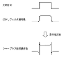
本実施形態におけるシャープネス処理としては、アンシャープマスク処理を用いる。図7に、アンシャープマスク処理の概要を示す。同図に示すようにアンシャープマスク処理は、注目画素を中心とした局所領域に対してぼかしフィルタを適用し、ぼかし処理前後の画素値の差分を、注目画素の画素値に反映することで輪郭強調を実現する処理である。 An unsharp mask process is used as the sharpness process in the present embodiment. FIG. 7 shows an outline of unsharp mask processing. As shown in the figure, the unsharp mask process applies a blur filter to the local area centered on the target pixel, and reflects the difference between the pixel values before and after the blur process on the pixel value of the target pixel. This is a process for realizing emphasis.
処理対象の画素値Pに対するアンシャープマスク処理は、処理適用後画素値P'、ぼかしフィルタの半径R、適用量A(%)を用いて以下の式(1)で表現できる。 The unsharp mask process for the pixel value P to be processed can be expressed by the following equation (1) using the post-application pixel value P ′, the blurring filter radius R, and the application amount A (%).
P'(i,j)=P(i,j)+(P(i,j)−F(i,j,R))×A/100 ・・・(1)
式(1)においてF(i,j,R)は、画素P(i,j)に対して半径Rのぼかしフィルタを適用して得られる画素値である。本実施形態におけるぼかし処理としては、ガウスぼかしを用いる。ガウスぼかしとは、処理対象画素からの距離に応じてガウス分布による重み付けを行って平均化を行う処理であり、自然な処理結果を得ることができる。また、ぼかしフィルタの半径Rの大きさは、シャープネス処理を適用したい画像上の周波の波長に関係する。すなわち、Rが小さいほど細かい模様が強調され、Rが大きいほど緩やかな模様が強調される。
P ′ (i, j) = P (i, j) + (P (i, j) −F (i, j, R)) × A / 100 (1)
In Equation (1), F (i, j, R) is a pixel value obtained by applying a blurring filter having a radius R to the pixel P (i, j). Gaussian blur is used as the blur processing in the present embodiment. Gaussian blur is a process of performing averaging by weighting with a Gaussian distribution according to the distance from the processing target pixel, and a natural processing result can be obtained. The size of the radius R of the blurring filter is related to the wavelength of the frequency on the image to which the sharpness processing is to be applied. That is, as R is smaller, a finer pattern is emphasized, and as R is larger, a gentler pattern is emphasized.
図8は、本実施形態におけるシャープネス処理を示すフローチャートである。 FIG. 8 is a flowchart showing sharpness processing in the present embodiment.
まずステップS801において、処理対象となる画像データに対して、仮のシャープネス処理パラメータとして、半径rおよび適用量aを設定しておく。そしてステップS802で、画素参照用の変数i,jを0に初期化する。 First, in step S801, a radius r and an application amount a are set as temporary sharpness processing parameters for image data to be processed. In step S802, pixel reference variables i and j are initialized to zero.
ステップS803では、処理対象画素P(i,j)に対応する距離マップ上のデータd(i,j)を参照し、局所的な距離の変化量δdを取得する。なお、局所的な距離の変化量δdの算出方法については後述する。 In step S803, referring to the data d (i, j) on the distance map corresponding to the processing target pixel P (i, j), a local distance change amount δd is obtained. A method for calculating the local distance change amount δd will be described later.
ステップS804では、ステップS801で算出した仮のシャープネス処理パラメータrおよびaを、ステップS803で求めた局所的な距離の変化量δdを用いて補正し、シャープネス処理パラメータRおよびAを決定する。なお、シャープネス処理パラメータの補正方法の詳細については後述する。 In step S804, the temporary sharpness processing parameters r and a calculated in step S801 are corrected using the local distance variation δd obtained in step S803, and the sharpness processing parameters R and A are determined. The details of the sharpness processing parameter correction method will be described later.
ステップS805では、ステップS804で決定したシャープネス処理パラメータR,Aにしたがって、処理対象画素に対してシャープネス処理を適用する。そしてステップS806において、画素参照用変数i,jを更新する。この更新はすなわち、iを1づつインクリメントしていき、iが処理対象画像データの幅と同じ値になった場合に、iを0にしてjをインクリメントする。 In step S805, sharpness processing is applied to the processing target pixel in accordance with the sharpness processing parameters R and A determined in step S804. In step S806, the pixel reference variables i and j are updated. In this update, i is incremented by 1, and when i becomes the same value as the width of the processing target image data, i is set to 0 and j is incremented.
ステップS807では、全ての画素に対してシャープネス処理を適用したか否かを判定し、処理を適用していない画素がある場合にはステップS803へ戻る。一方、全ての画素に対して処理を適用した場合、つまりjが処理対象画像データの高さと同じ値になった場合には、処理を終了する。 In step S807, it is determined whether or not sharpness processing has been applied to all pixels. If there is a pixel to which processing is not applied, the process returns to step S803. On the other hand, when the processing is applied to all the pixels, that is, when j becomes the same value as the height of the processing target image data, the processing is ended.
なお、本実施形態において設定される仮のシャープネス処理パラメータとしては、予めユーザによって指定された半径r、適用量aであるとする。例えば、仮のシャープネス処理パラメータの初期値として、半径rを10、適用量aを100として設定する。 Note that the provisional sharpness processing parameters set in the present embodiment are assumed to be a radius r and an application amount a specified in advance by the user. For example, the radius r is set to 10 and the application amount a is set to 100 as the initial value of the temporary sharpness processing parameter.
●局所的な距離の変化量δdの算出方法
ここで、上述したステップS803における局所的な距離の変化量δdの算出方法について、詳細に説明する。
Calculation Method for Local Distance Change δd Here, the method for calculating the local distance change δd in step S803 will be described in detail.
処理対象である注目画素P(i,j)に対応する距離マップ上のデータをd(i,j)、該注目画素P(i,j)を中心とした半径Lの領域に含まれる全ての周辺画素に対応する距離マップ上のデータをd(p,q)とする。この場合、本実施形態では、注目画素Pに対応する局所的な距離の変化量δd(i,j)を、下式で定義する。 Data on the distance map corresponding to the target pixel P (i, j) to be processed is d (i, j), and all of the data included in the region of radius L centered on the target pixel P (i, j) Let d (p, q) be the data on the distance map corresponding to the surrounding pixels. In this case, in this embodiment, the local distance variation δd (i, j) corresponding to the target pixel P is defined by the following equation.
δd(i,j)=Σ(|d(i,j)−d(p,q)|)/n ・・・(2)
つまり、注目画素Pと周辺画素との物体距離の差の絶対値を平均化した値を、局所的な距離の変化量δdとする。ここでnは、周辺画素と判断された画素のピクセル数である。なお、アンシャープマスク処理で用いる半径Rと、周辺画素の判定用の半径Lは独立に決定しても良い。
δd (i, j) = Σ (| d (i, j) −d (p, q) |) / n (2)
That is, a value obtained by averaging the absolute value of the difference in object distance between the target pixel P and the surrounding pixels is set as a local distance change amount δd. Here, n is the number of pixels determined to be peripheral pixels. Note that the radius R used in the unsharp mask process and the radius L for determining peripheral pixels may be determined independently.
したがって、周辺画素も含めた領域が同一被写体に含まれる場合、δd(i,j)は小さくなり、異なるオブジェクトに跨る場合にはδd(i,j)が大きくなる可能性が高くなることが分かる。特に、主要被写体と背景が離れている場合、その境界付近ではδd(i,j)が非常に大きな値をとる。 Therefore, it can be seen that δd (i, j) is small when an area including peripheral pixels is included in the same subject, and that δd (i, j) is likely to be large when straddling different objects. . In particular, when the main subject is far from the background, δd (i, j) takes a very large value near the boundary.
なお本実施形態では、処理対象画素と周辺画素との距離に関係なく、半径Lに含まれる画素を全て対等に扱う例を示したが、例えばガウス分布などを用いて処理対象画素と周辺画素の距離を考慮して、局所的な距離の変化量δdを算出しても良い。 In this embodiment, an example in which all the pixels included in the radius L are treated equally regardless of the distance between the processing target pixel and the surrounding pixels has been described. However, for example, a Gaussian distribution or the like is used. The local distance variation δd may be calculated in consideration of the distance.
●シャープネス処理パラメータの補正方法
次に、上述したステップS804におけるシャープネス処理パラメータの補正方法について、詳細に説明する。
Sharpness Processing Parameter Correction Method Next, the sharpness processing parameter correction method in step S804 described above will be described in detail.
本実施形態では、シャープネス処理パラメータのうち、適用量Aを変化させる。処理対象となる注目画素P(i,j)に対するシャープネス適用量A(i,j)は、次式を用いて算出する。 In the present embodiment, the application amount A is changed among the sharpness processing parameters. The sharpness application amount A (i, j) for the target pixel P (i, j) to be processed is calculated using the following equation.
A(i,j)=a×(1−1/δd(i,j)) ・・・(3)
式(3)においてaは、ステップS801で仮のシャープネス適用パラメータとして設定された適用量である。式(3)によれば、局所的な距離の変化量δd(i,j)が大きいほど、シャープネス適用量A(i,j)が大きくなることが分かる。したがって本実施形態によれば、周囲画素との距離の変化量が大きい画素に対して、より強いシャープネスを適用することができる。
A (i, j) = a × (1-1 / δd (i, j)) (3)
In Expression (3), a is the application amount set as a temporary sharpness application parameter in step S801. According to Expression (3), it is understood that the sharpness application amount A (i, j) increases as the local distance change amount δd (i, j) increases. Therefore, according to the present embodiment, it is possible to apply a stronger sharpness to a pixel whose amount of change in distance from surrounding pixels is large.
以上説明したように本実施形態によれば、局所的な距離の変化量に応じてシャープネス処理を適用する。すなわち、局所的な距離の変化量が大きいほど先鋭度が向上するようにシャープネスを適用することによって、被写体と背景の分離性を向上させることが可能となる。 As described above, according to the present embodiment, the sharpness process is applied in accordance with the local distance change amount. That is, it is possible to improve the separation between the subject and the background by applying sharpness so that the sharpness is improved as the amount of change in local distance is larger.
<第2実施形態>
以下、本発明に係る第2実施形態について説明する。
Second Embodiment
Hereinafter, a second embodiment according to the present invention will be described.
上述した第1実施形態で説明したように、アンシャープマスクによる輪郭強調処理は、フィルタの半径Rが、輪郭強調の対象となる周波数に関係する。そのため、半径Rが小さい場合には被写体表面の微細なテクスチャが強調され、半径Rが大きい場合にはオブジェクトとその他の領域との境界を強調するのに適している。 As described in the first embodiment described above, in the edge enhancement process using the unsharp mask, the radius R of the filter is related to the frequency to be subjected to edge enhancement. Therefore, when the radius R is small, the fine texture on the subject surface is emphasized, and when the radius R is large, it is suitable for enhancing the boundary between the object and other regions.
そこで第2実施形態では、シャープネスの強さではなく、シャープネスフィルタ(アンシャープマスク)の半径Rを、注目画素とその周囲画素との局所的な距離の変化量δdによって決定する方法について説明する。 Therefore, in the second embodiment, a method for determining the radius R of the sharpness filter (unsharp mask), not the strength of sharpness, based on the local distance variation δd between the pixel of interest and its surrounding pixels will be described.
第2実施形態におけるシャープネス処理は、上述した第1実施形態と同様に図8のフローチャートに示す手順によって実行されるが、シャープネス処理パラメータの補正方法が異なる。また、局所的な距離の変化量δdの算出方法については、上述した第1実施形態と同様の方法であっても良いが、第2実施形態ではさらに別の方法を示す。すなわち第2実施形態におけるシャープネス処理としては、図8のステップS803における局所的な距離の変化量δdの算出方法と、ステップS804におけるシャープネス処理パラメータの補正方法が、上述した第1実施形態とは異なる。以下、これら第1実施形態との相違点について説明する。 The sharpness processing in the second embodiment is executed according to the procedure shown in the flowchart of FIG. 8 as in the first embodiment described above, but the sharpness processing parameter correction method is different. Further, the local distance change amount δd may be calculated by the same method as in the first embodiment described above, but the second embodiment shows still another method. That is, as the sharpness processing in the second embodiment, the local distance change amount δd calculation method in step S803 in FIG. 8 and the sharpness processing parameter correction method in step S804 are different from those in the first embodiment described above. . Hereinafter, differences from the first embodiment will be described.
●局所的な距離の変化量δdの算出方法
まず、ステップS803における局所的な距離の変化量δdの算出方法について、詳細に説明する。
First, a method for calculating the local distance change amount δd will be described in detail in step S803.
第2実施形態では、処理対象画素を中心とした4方向の勾配を考慮して、局所的な距離の変化量δdを算出する。 In the second embodiment, the local distance variation δd is calculated in consideration of the gradients in the four directions centered on the processing target pixel.
図9に、第2実施形態における局所的な距離の変化量δdの算出処理のフローチャートを示す。 FIG. 9 shows a flowchart of a calculation process of the local distance change amount δd in the second embodiment.
まずステップS901において、図10に示すように処理対象画素Pを中心とした4組の周辺画素対を勾配算出画素対(A1-A2,B1-B2,C1-C2,D1-D2)として選択する。そしてステップS902において、上記4組のうち、勾配算出画素対間の距離変化が単調増加、あるいは単調減少である画素対を選択する。そして、選択された画素対のそれぞれについて、次式によって距離の変化量ΔDを算出する。 First, in step S901, as shown in FIG. 10, four peripheral pixel pairs centered on the processing target pixel P are selected as gradient calculation pixel pairs (A1-A2, B1-B2, C1-C2, D1-D2). . In step S902, a pixel pair whose distance change between the gradient calculation pixel pairs is monotonously increasing or monotonically decreasing is selected from the above four sets. Then, for each of the selected pixel pairs, a distance change amount ΔD is calculated by the following equation.
ΔD=(|P1―P(i,j)|+|P2―P(i,j)|)/2 ・・・(4)
式(4)においてP1,P2は、勾配算出画素対として選択された2画素それぞれの物体距離とする。
ΔD = (| P1-P (i, j) | + | P2-P (i, j) |) / 2 (4)
In Equation (4), P1 and P2 are the object distances of the two pixels selected as the gradient calculation pixel pair.
そしてステップS903では、ステップS902で1つ以上の変化量ΔDが得られたか否かを判定し、得られた場合にはステップS904へ進み、得られなかった場合にはステップS905へ進む。つまり、ステップS901において選択された4組から勾配算出画素対間の距離変化が単調増加、あるいは単調減少である画素対が選択された場合はステップS904に進み、選択されなかった場合はステップ905へ進む。 In step S903, it is determined whether or not one or more change amounts ΔD are obtained in step S902. If obtained, the process proceeds to step S904. If not obtained, the process proceeds to step S905. That is, if a pixel pair whose distance change between the gradient calculation pixel pairs is monotonously increasing or monotonically decreasing is selected from the four groups selected in step S901, the process proceeds to step S904, and if not, the process proceeds to step 905. move on.
ステップS904では、得られた変化量ΔDを局所的な距離の変化量δdを決定する。このとき、複数の勾配算出画素対についてΔDが得られた、すなわち複数の勾配算出画素対の間が単調増加、あるいは単調減少であった場合には、距離の変化量ΔDが最大になる値を選択して、これを局所的な距離の変化量δdとする。 In step S904, the obtained change amount ΔD is determined as a local distance change amount δd. At this time, when ΔD is obtained for a plurality of gradient calculation pixel pairs, that is, when the distance between the plurality of gradient calculation pixel pairs is monotonously increasing or monotonically decreasing, a value that maximizes the distance change amount ΔD is obtained. This is selected and set as the local distance change amount δd.
一方、ステップS905では、上述した第1実施形態と同様の方法によって、局所的な距離の変化量δdを算出する。 On the other hand, in step S905, the local distance variation δd is calculated by the same method as in the first embodiment described above.
第2実施形態では、以上のような処理により、被写体の輪郭をより強く反映した局所的な距離の変化量δdを算出することができる。 In the second embodiment, the local distance variation δd that more strongly reflects the contour of the subject can be calculated by the processing described above.
なお、第2実施形態では1つの勾配算出画素対における距離の変化量ΔDを選択し、これを局所的な距離の変化量δdとして算出する例を示したが、最大n個(例えば2つ)の勾配算出画素対を選択し、ΔDの加重平均等を行ってδdを算出しても良い。また、選択された勾配算出画素対の周辺において、隣接する画素の局所的な距離の変化量δdが極端に変動する可能性がある。そのため、一旦全ての画素について局所的な距離の変化量を算出し、ガウスぼかしフィルタ等を適用して隣接画素間の変動を抑制しても良い。 In the second embodiment, an example in which the distance change amount ΔD in one gradient calculation pixel pair is selected and calculated as the local distance change amount δd is shown, but a maximum of n pieces (for example, two) is shown. Δd may be calculated by selecting a gradient calculating pixel pair and performing a weighted average of ΔD or the like. In addition, there is a possibility that the local distance change amount δd of adjacent pixels varies extremely around the selected gradient calculation pixel pair. For this reason, a local distance change amount may be once calculated for all the pixels, and a variation between adjacent pixels may be suppressed by applying a Gaussian blur filter or the like.
●シャープネス処理パラメータの補正方法
次に、ステップS804におけるシャープネス処理パラメータの補正方法について、詳細に説明する。
Sharpness Processing Parameter Correction Method Next, the sharpness processing parameter correction method in step S804 will be described in detail.
第2実施形態では、シャープネス処理パラメータのうち、シャープネスフィルタの半径Rを変化させる。処理対象となる注目画素P(i,j)に対するシャープネス処理の半径R(i,j)は、次式を用いて算出する。 In the second embodiment, among the sharpness processing parameters, the radius R of the sharpness filter is changed. The radius R (i, j) of sharpness processing for the target pixel P (i, j) to be processed is calculated using the following equation.
R(i,j)=r×(1−1/δd(i,j)) ・・・(5)
式(5)においてrは、ステップS801で仮のシャープネス適用パラメータとして設定された半径である。なお、式(5)によって半径Rが0.5未満として算出された場合には、R=0.5とする。式(5)によれば、局所的な距離の変化量δd(i,j)が大きいほど、シャープネス処理の半径R(i,j)が大きくなることが分かる。したがって本実施形態によれば、周囲画素との距離の変化量が大きいほど、低い周波数の領域に対してシャープネスを適用することができる。
R (i, j) = r × (1-1 / δd (i, j)) (5)
In equation (5), r is a radius set as a temporary sharpness application parameter in step S801. In addition, when the radius R is calculated as less than 0.5 by the equation (5), R = 0.5. According to equation (5), it can be seen that the radius R (i, j) of the sharpness processing increases as the local distance change amount δd (i, j) increases. Therefore, according to the present embodiment, the sharpness can be applied to the low frequency region as the amount of change in the distance from the surrounding pixels is larger.
アンシャープマスク処理の半径を小さくすると、同じ適用量であっても相対的に弱くシャープネスがかかって見える場合がある。そこで第2実施形態においては、半径Rとあわせて適用量Aについても、次式のように補正する。 If the radius of the unsharp mask process is reduced, it may appear relatively weak and sharp even with the same application amount. Therefore, in the second embodiment, the application amount A is corrected together with the radius R as follows.
A(i,j)=a×(w−R(i,j)/r) ・・・(6)
式(6)においてaおよびrは、ステップS801で仮のシャープネス適用パラメータとして設定された適用量および半径である。またwは、シャープネスを強く適用させるための係数であり、局所的な距離の変化量δd(i,j)が小さいために半径Rが小さくなってしまった場合に、最大w倍強く、シャープネスが適用されるようにする。例えば第2実施形態では、w=2とする。
A (i, j) = a × (w−R (i, j) / r) (6)
In equation (6), a and r are the application amount and radius set as the provisional sharpness application parameters in step S801. Further, w is a coefficient for applying sharpness strongly. When the radius R becomes small because the local distance change amount δd (i, j) is small, the maximum sharpness is w times. To be applied. For example, in the second embodiment, w = 2.
一般に、撮影距離が近いと被写体と背景の距離差が大きくなりやすく、被写界深度は浅くなる傾向にある。逆に、撮影距離が遠いと被写界深度が深くなりやすい。また、レンズのF値が小さいほど被写界深度が浅くなる。さらに、レンズの焦点距離が小さいほど、被写界深度が深くなりやすいという傾向がある。 Generally, when the shooting distance is short, the distance difference between the subject and the background tends to increase, and the depth of field tends to be shallow. Conversely, if the shooting distance is long, the depth of field tends to be deep. Also, the smaller the F value of the lens, the shallower the depth of field. Furthermore, there is a tendency that the depth of field tends to be deeper as the focal length of the lens is smaller.
被写界深度が浅い場合、主要被写体と背景をよりはっきりと分離させたいという撮影意図があることが多い。したがってこの場合、被写界深度が浅く局所距離差が大きいほど、シャープネス適用半径Rが大きくなるように設定すれば良い。逆に、被写界深度外のぼけた領域に対して、半径Rに小さい値を指定してアンシャープマスク処理を適用すると、ノイズを強調するだけになってしまうことが多い。したがってこの場合、同一被写体が被写界深度内と被写界深度外に跨る可能性が高いため、被写界深度が浅く局所距離差が小さいほど、シャープネス適用量Aが小さくなるように設定すれば良い。 When the depth of field is shallow, there are often intentions for shooting to separate the main subject and the background more clearly. Therefore, in this case, the sharpness application radius R may be set to be larger as the depth of field is shallower and the local distance difference is larger. Conversely, if an unsharp mask process is applied to a blurred region outside the depth of field and a small value is specified for the radius R, the noise is often only emphasized. Therefore, in this case, since the same subject is likely to straddle the depth of field and outside the depth of field, the sharpness application amount A is set to be smaller as the depth of field is shallower and the local distance difference is smaller. It ’s fine.
このように第2実施形態では、さらに撮影画像の撮影条件(撮影距離、レンズのF値、レンズの焦点距離等)を取得し、該条件と物体距離の差に基づいて、シャープネス適用パラメータ設定を行っても良い。 As described above, in the second embodiment, the shooting conditions (shooting distance, lens F value, lens focal length, etc.) of the shot image are further acquired, and the sharpness application parameter setting is set based on the difference between the conditions and the object distance. You can go.
また、第2実施形態では、式(4)〜(6)のシャープネス適用パラメータの補正量演算式において、撮影距離からの相対距離を考慮していないが、局所的な距離の変化量とあわせて該相対距離を用いて、シャープネス適用パラメータを算出しても良い。 Further, in the second embodiment, the sharpness application parameter correction amount calculation formulas (4) to (6) do not take into account the relative distance from the shooting distance, but in addition to the local distance change amount. The sharpness application parameter may be calculated using the relative distance.
●シャープネス処理の具体例
ここで、第2実施形態におけるシャープネス処理の具体例を示す。
Specific Example of Sharpness Processing Here, a specific example of sharpness processing in the second embodiment is shown.
以下、図11のようなスタジオを用意して被写体(この例の場合、チャート)を撮影した場合を例として説明する。 Hereinafter, a case where a studio as shown in FIG. 11 is prepared and a subject (in this example, a chart) is photographed will be described as an example.
特にシャープネスを適用しない場合、撮影されたオリジナル画像は図12Aに示すように得られる。 In particular, when sharpness is not applied, a photographed original image is obtained as shown in FIG. 12A.
また、画像全体に一律に小さい半径のシャープネスを適用すると、図12Bに示すような撮影画像が得られる。図12Bによれば、被写体(チャート)を拡大すると微細なテクスチャが強調されるものの、縮小表示すると、解像感はオリジナル画像に近いものになってしまう。逆に、半径の大きいシャープネスを画面全体に適用した場合、図12Cに示すような撮影画像が得られる。図12Cによれば、縮小画像では被写体におけるエッジ部および背景との境界部が太くなって先鋭度が増すものの、被写体表面のテクスチャは強調されず、場合によっては潰れてしまうため、拡大表示した場合の精細感に欠けてしまう。 Moreover, when sharpness with a small radius is uniformly applied to the entire image, a captured image as shown in FIG. 12B is obtained. According to FIG. 12B, when a subject (chart) is enlarged, a fine texture is emphasized, but when reduced, the sense of resolution becomes close to the original image. Conversely, when sharpness with a large radius is applied to the entire screen, a captured image as shown in FIG. 12C is obtained. According to FIG. 12C, in the reduced image, the edge portion of the subject and the boundary between the background and the background become thick and sharpness is increased, but the texture of the subject surface is not emphasized and is sometimes crushed. Lacks the sense of detail.
そこで、第2実施形態の方法、すなわちアンシャープマスクの半径Rを局所的な距離の変化量に基づいて決定してシャープネスを適用すると、図12Dに示すような結果が得られる。図12Dによれば、被写体の周囲部分(境界部分)には半径の大きいアンシャープマスク処理が適用され、被写体の周囲部分以外や背景紙部分には半径の小さいアンシャープマスク処理が適用される。したがって、画像を拡大した場合には被写体表面のテクスチャがはっきりと描写され、画像を縮小した場合でも被写体のエッジ部が太くなり、被写体と背景がくっきりと分離するように、撮影画像データを表示することができる。 Therefore, when the method of the second embodiment, that is, the sharpness is applied by determining the radius R of the unsharp mask based on the local distance change amount, the result shown in FIG. 12D is obtained. According to FIG. 12D, an unsharp mask process with a large radius is applied to the peripheral part (boundary part) of the subject, and an unsharp mask process with a small radius is applied to the part other than the peripheral part of the subject and the background paper part. Therefore, when the image is enlarged, the texture of the subject surface is clearly depicted, and even when the image is reduced, the edge portion of the subject becomes thick and the photographed image data is displayed so that the subject and the background are clearly separated. be able to.
以上説明したように第2実施形態によれば、アンシャープマスクの半径Rを局所的な距離の変化量δdによって決定する。これにより、画面全体に同じパラメータでアンシャープマスク処理を適用した場合に比べ、被写体表面の細かいテクスチャを強調しつつ、被写体と背景の分離性を向上した画像を得ることができ、被写界深度に関わらず常に好適な撮影画像を得ることができる。 As described above, according to the second embodiment, the radius R of the unsharp mask is determined by the local distance variation δd. As a result, compared to when unsharp mask processing is applied to the entire screen with the same parameters, it is possible to obtain an image with enhanced subject separation and background separation while enhancing the fine texture of the subject surface. Regardless of the case, a suitable photographed image can always be obtained.
なお、第2実施形態では、局所的な距離の変化量δdに応じてシャープネスフィルタの半径R、すなわちフィルタサイズを設定する例を示したが、該変化量δdに応じてフィルタ係数を制御するようにしても良い。 In the second embodiment, the radius R of the sharpness filter, that is, the filter size is set according to the local distance change amount δd. However, the filter coefficient is controlled according to the change amount δd. Anyway.
<その他の実施形態>
本発明は例えば、システム、装置、方法、プログラム若しくは記憶媒体(記録媒体)等としての実施態様をとることが可能である。具体的には、複数の機器(例えば、ホストコンピュータ、インタフェース機器、撮像装置、webアプリケーション、プリンタ等)から構成されるシステムに適用しても良いし、また、一つの機器からなる装置に適用しても良い。
<Other embodiments>
The present invention can take the form of, for example, a system, apparatus, method, program, or storage medium (recording medium). Specifically, the present invention may be applied to a system composed of a plurality of devices (for example, a host computer, an interface device, an imaging device, a web application, a printer, etc.), or applied to a device composed of a single device. May be.
尚本発明は、前述した実施形態の機能を実現するソフトウェアのプログラムを、システムあるいは装置に直接あるいは遠隔から供給し、そのシステムあるいは装置のコンピュータが該供給されたプログラムコードを読み出して実行することによっても達成される。なお、この場合のプログラムとは、実施形態において図に示したフローチャートに対応したコンピュータ可読のプログラムである。 In the present invention, a software program for realizing the functions of the above-described embodiments is supplied directly or remotely to a system or apparatus, and the computer of the system or apparatus reads and executes the supplied program code. Is also achieved. The program in this case is a computer-readable program corresponding to the flowchart shown in the drawing in the embodiment.
従って、本発明の機能処理をコンピュータで実現するために、該コンピュータにインストールされるプログラムコード自体も本発明を実現するものである。つまり、本発明は、本発明の機能処理を実現するためのコンピュータプログラム自体も含まれる。 Accordingly, since the functions of the present invention are implemented by computer, the program code installed in the computer also implements the present invention. In other words, the present invention includes a computer program itself for realizing the functional processing of the present invention.
その場合、プログラムの機能を有していれば、オブジェクトコード、インタプリタにより実行されるプログラム、OSに供給するスクリプトデータ等の形態であっても良い。 In that case, as long as it has the function of a program, it may be in the form of object code, a program executed by an interpreter, script data supplied to the OS, or the like.
プログラムを供給するための記録媒体としては、以下に示す媒体がある。例えば、フロッピー(登録商標)ディスク、ハードディスク、光ディスク、光磁気ディスク、MO、CD-ROM、CD-R、CD-RW、磁気テープ、不揮発性のメモリカード、ROM、DVD(DVD-ROM,DVD-R)などである。 Recording media for supplying the program include the following media. For example, floppy disk, hard disk, optical disk, magneto-optical disk, MO, CD-ROM, CD-R, CD-RW, magnetic tape, nonvolatile memory card, ROM, DVD (DVD-ROM, DVD- R).
プログラムの供給方法としては、以下に示す方法も可能である。すなわち、クライアントコンピュータのブラウザからインターネットのホームページに接続し、そこから本発明のコンピュータプログラムそのもの(又は圧縮され自動インストール機能を含むファイル)をハードディスク等の記録媒体にダウンロードする。また、本発明のプログラムを構成するプログラムコードを複数のファイルに分割し、それぞれのファイルを異なるホームページからダウンロードすることによっても実現可能である。つまり、本発明の機能処理をコンピュータで実現するためのプログラムファイルを複数のユーザに対してダウンロードさせるWWWサーバも、本発明に含まれるものである。 As a program supply method, the following method is also possible. That is, the browser of the client computer is connected to a homepage on the Internet, and the computer program itself (or a compressed file including an automatic installation function) of the present invention is downloaded to a recording medium such as a hard disk. It can also be realized by dividing the program code constituting the program of the present invention into a plurality of files and downloading each file from a different homepage. That is, a WWW server that allows a plurality of users to download a program file for realizing the functional processing of the present invention on a computer is also included in the present invention.
また、本発明のプログラムを暗号化してCD-ROM等の記憶媒体に格納してユーザに配布し、所定の条件をクリアしたユーザに対し、インターネットを介してホームページから暗号化を解く鍵情報をダウンロードさせることも可能である。すなわち該ユーザは、その鍵情報を使用することによって暗号化されたプログラムを実行し、コンピュータにインストールさせることができる。 In addition, the program of the present invention is encrypted, stored in a storage medium such as a CD-ROM, distributed to users, and key information for decryption is downloaded from a homepage via the Internet to users who have cleared predetermined conditions. It is also possible to make it. That is, the user can execute the encrypted program by using the key information and install it on the computer.
また、コンピュータが、読み出したプログラムを実行することによって、前述した実施形態の機能が実現される。さらに、そのプログラムの指示に基づき、コンピュータ上で稼動しているOSなどが、実際の処理の一部または全部を行い、その処理によっても前述した実施形態の機能が実現され得る。 Further, the functions of the above-described embodiments are realized by the computer executing the read program. Furthermore, based on the instructions of the program, an OS or the like running on the computer performs part or all of the actual processing, and the functions of the above-described embodiments can also be realized by the processing.
さらに、記録媒体から読み出されたプログラムが、コンピュータに挿入された機能拡張ボードやコンピュータに接続された機能拡張ユニットに備わるメモリに書き込まれた後、実行されることによっても、前述した実施形態の機能が実現される。すなわち、該プログラムの指示に基づき、その機能拡張ボードや機能拡張ユニットに備わるCPUなどが実際の処理の一部または全部を行うことが可能である。 Further, the program read from the recording medium is written in a memory provided in a function expansion board inserted into the computer or a function expansion unit connected to the computer, and then executed, so that the program of the above-described embodiment can be obtained. Function is realized. That is, based on the instructions of the program, the CPU provided in the function expansion board or function expansion unit can perform part or all of the actual processing.
Claims (15)
前記撮影画像の各画素について、前記被写体までの距離を示す物体距離の情報を取得する取得手段と、
前記撮影画像における注目画素と該注目画素の周辺画素とで構成される画素群内の2つの画素についての前記物体距離の差を算出する算出手段と、
該算出された前記物体距離の差を用いて、前記注目画素に対するシャープネス処理のパラメータを設定するパラメータ設定手段と、
該設定されたパラメータを用いて、前記注目画素に対するシャープネス処理を行うシャープネス処理手段と、
を有し、
前記パラメータ設定手段は、前記パラメータとして、シャープネス処理のフィルタサイズを設定することを特徴とする画像処理装置。 An image processing apparatus that corrects a captured image obtained by photographing a subject,
Acquisition means for acquiring object distance information indicating a distance to the subject for each pixel of the captured image;
Calculating means for calculating a difference between the object distances for two pixels in a pixel group including a target pixel in the captured image and a peripheral pixel of the target pixel;
Parameter setting means for setting a sharpness processing parameter for the target pixel using the calculated difference in the object distance;
Sharpness processing means for performing sharpness processing on the target pixel using the set parameters;
I have a,
The image processing apparatus , wherein the parameter setting means sets a filter size for sharpness processing as the parameter .
前記撮影画像の各画素について、前記被写体までの距離を示す物体距離の情報を取得する取得手段と、 Acquisition means for acquiring object distance information indicating a distance to the subject for each pixel of the captured image;
前記撮影画像における注目画素と該注目画素の周辺画素とで構成される画素群内の2つの画素についての前記物体距離の差を算出する算出手段と、 Calculating means for calculating a difference between the object distances for two pixels in a pixel group including a target pixel in the captured image and a peripheral pixel of the target pixel;
該算出された前記物体距離の差を用いて、前記注目画素に対するアンシャープマスク処理のパラメータを設定するパラメータ設定手段と、 Parameter setting means for setting an unsharp mask process parameter for the target pixel using the calculated difference in the object distance;
該設定されたパラメータを用いて、前記注目画素に対するアンシャープマスク処理を行うアンシャープマスク処理手段と、 Unsharp mask processing means for performing unsharp mask processing on the pixel of interest using the set parameters;
を有し、Have
前記パラメータ設定手段は、前記パラメータとして、アンシャープマスク処理の適用量を設定することを特徴とする画像処理装置。 The image processing apparatus, wherein the parameter setting means sets an application amount of unsharp mask processing as the parameter.
前記算出手段は、前記距離マップに基づいて、前記物体距離の差を算出することを特徴とする請求項1乃至5のいずれか1項に記載の画像処理装置。 The acquisition unit generates a distance map indicating object distance information for each pixel of the captured image,
The image processing apparatus according to claim 1, wherein the calculation unit calculates a difference between the object distances based on the distance map.
前記パラメータ設定手段は、前記撮影条件と前記物体距離の差に基づいて、前記パラメータを設定することを特徴とする請求項1乃至10のいずれか1項に記載の画像処理装置。 Furthermore, it has an imaging condition acquisition means for acquiring the imaging conditions of the captured image,
The image processing apparatus according to claim 1, wherein the parameter setting unit sets the parameter based on a difference between the imaging condition and the object distance.
取得手段が、前記撮影画像の各画素について、前記被写体までの距離を示す物体距離の情報を取得する取得ステップと、
算出手段が、前記撮影画像における注目画素と該注目画素の周辺画素とで構成される画素群内の2つの画素についての前記物体距離の差を算出する算出ステップと、
パラメータ設定手段が、該算出された前記物体距離の差を用いて、前記注目画素に対するシャープネス処理のパラメータを設定するパラメータ設定ステップと、
シャープネス処理手段が、該設定されたパラメータを用いて、前記注目画素に対するシャープネス処理を行うシャープネス処理ステップと、
を有し、
前記パラメータ設定ステップでは、前記パラメータとして、シャープネス処理のフィルタサイズを設定することを特徴とする画像処理方法。 An image processing method performed by an image processing apparatus that corrects a captured image obtained by photographing a subject,
An obtaining step for obtaining information of an object distance indicating a distance to the subject for each pixel of the captured image;
A calculating step for calculating a difference between the object distances for two pixels in a pixel group including a target pixel and a peripheral pixel of the target pixel in the captured image;
A parameter setting step for setting a parameter of sharpness processing for the target pixel using the calculated difference in the object distance;
A sharpness processing step, a sharpness processing step for performing sharpness processing on the pixel of interest using the set parameters;
I have a,
In the parameter setting step, a filter size of sharpness processing is set as the parameter .
取得手段が、前記撮影画像の各画素について、前記被写体までの距離を示す物体距離の情報を取得する取得ステップと、 An obtaining step for obtaining information of an object distance indicating a distance to the subject for each pixel of the captured image;
算出手段が、前記撮影画像における注目画素と該注目画素の周辺画素とで構成される画素群内の2つの画素についての前記物体距離の差を算出する算出ステップと、 A calculating step for calculating a difference between the object distances for two pixels in a pixel group including a target pixel and a peripheral pixel of the target pixel in the captured image;
パラメータ設定手段が、該算出された前記物体距離の差を用いて、前記注目画素に対するアンシャープマスク処理のパラメータを設定するパラメータ設定ステップと、 A parameter setting step for setting an unsharp mask process parameter for the pixel of interest using the calculated difference in the object distance;
アンシャープマスク処理手段が、該設定されたパラメータを用いて、前記注目画素に対するアンシャープマスク処理を行うアンシャープマスク処理ステップと、 An unsharp mask processing means performs an unsharp mask processing step on the target pixel using the set parameter;
を有し、Have
前記パラメータ設定ステップでは、前記パラメータとして、アンシャープマスク処理の適用量を設定することを特徴とする画像処理方法。 In the parameter setting step, an application amount of unsharp mask processing is set as the parameter.
Priority Applications (2)
| Application Number | Priority Date | Filing Date | Title |
|---|---|---|---|
| JP2009003995A JP5230456B2 (en) | 2009-01-09 | 2009-01-09 | Image processing apparatus and image processing method |
| US12/646,874 US8335393B2 (en) | 2009-01-09 | 2009-12-23 | Image processing apparatus and image processing method |
Applications Claiming Priority (1)
| Application Number | Priority Date | Filing Date | Title |
|---|---|---|---|
| JP2009003995A JP5230456B2 (en) | 2009-01-09 | 2009-01-09 | Image processing apparatus and image processing method |
Publications (3)
| Publication Number | Publication Date |
|---|---|
| JP2010161744A JP2010161744A (en) | 2010-07-22 |
| JP2010161744A5 JP2010161744A5 (en) | 2012-02-02 |
| JP5230456B2 true JP5230456B2 (en) | 2013-07-10 |
Family
ID=42319146
Family Applications (1)
| Application Number | Title | Priority Date | Filing Date |
|---|---|---|---|
| JP2009003995A Active JP5230456B2 (en) | 2009-01-09 | 2009-01-09 | Image processing apparatus and image processing method |
Country Status (2)
| Country | Link |
|---|---|
| US (1) | US8335393B2 (en) |
| JP (1) | JP5230456B2 (en) |
Families Citing this family (24)
| Publication number | Priority date | Publication date | Assignee | Title |
|---|---|---|---|---|
| CA2956645A1 (en) | 2003-07-12 | 2005-03-31 | David A. Goldberg | Sensitive and rapid biodetection |
| US20120077206A1 (en) | 2003-07-12 | 2012-03-29 | Accelr8 Technology Corporation | Rapid Microbial Detection and Antimicrobial Susceptibility Testing |
| US9434937B2 (en) | 2011-03-07 | 2016-09-06 | Accelerate Diagnostics, Inc. | Rapid cell purification systems |
| US10254204B2 (en) | 2011-03-07 | 2019-04-09 | Accelerate Diagnostics, Inc. | Membrane-assisted purification |
| JP5818514B2 (en) * | 2011-05-27 | 2015-11-18 | キヤノン株式会社 | Image processing apparatus, image processing method, and program |
| JP5968107B2 (en) * | 2011-09-01 | 2016-08-10 | キヤノン株式会社 | Image processing method, image processing apparatus, and program |
| US20130094753A1 (en) * | 2011-10-18 | 2013-04-18 | Shane D. Voss | Filtering image data |
| WO2013058735A1 (en) | 2011-10-18 | 2013-04-25 | Hewlett-Packard Development Company, L.P. | Depth mask assisted video stabilization |
| JP5913934B2 (en) * | 2011-11-30 | 2016-05-11 | キヤノン株式会社 | Image processing apparatus, image processing method and program, and imaging apparatus having image processing apparatus |
| JP5893412B2 (en) * | 2012-01-13 | 2016-03-23 | キヤノン株式会社 | Imaging apparatus and control method thereof |
| JP5703255B2 (en) * | 2012-04-27 | 2015-04-15 | 株式会社東芝 | Image processing apparatus, image processing method, and program |
| JP2014048714A (en) * | 2012-08-29 | 2014-03-17 | Canon Inc | Image processing apparatus and image processing method |
| US9677109B2 (en) | 2013-03-15 | 2017-06-13 | Accelerate Diagnostics, Inc. | Rapid determination of microbial growth and antimicrobial susceptibility |
| TWI486616B (en) * | 2013-08-16 | 2015-06-01 | Sintai Optical Shenzhen Co Ltd | Optical system |
| JP6355315B2 (en) * | 2013-10-29 | 2018-07-11 | キヤノン株式会社 | Image processing apparatus, image processing method, and program |
| US10311550B2 (en) * | 2014-03-27 | 2019-06-04 | Noritsu Precision Co., Ltd. | Image processing device for eliminating graininess of image |
| CN106464798B (en) * | 2014-04-11 | 2018-01-05 | 富士胶片株式会社 | Image processing apparatus, camera device, image processing method and recording medium |
| WO2016161022A2 (en) | 2015-03-30 | 2016-10-06 | Accerlate Diagnostics, Inc. | Instrument and system for rapid microorganism identification and antimicrobial agent susceptibility testing |
| US10253355B2 (en) | 2015-03-30 | 2019-04-09 | Accelerate Diagnostics, Inc. | Instrument and system for rapid microorganism identification and antimicrobial agent susceptibility testing |
| JP6529360B2 (en) * | 2015-06-26 | 2019-06-12 | キヤノン株式会社 | Image processing apparatus, imaging apparatus, image processing method and program |
| JP6949494B2 (en) * | 2017-01-17 | 2021-10-13 | キヤノン株式会社 | Image processing equipment and image processing methods, imaging equipment, programs |
| JP7137313B2 (en) * | 2018-02-15 | 2022-09-14 | キヤノン株式会社 | Output device, image processing method and program |
| US11792534B2 (en) | 2018-08-30 | 2023-10-17 | Sony Corporation | Signal processing device, signal processing method, and image capture device |
| CN111242887B (en) * | 2019-04-27 | 2020-11-24 | 合肥耀世同辉科技有限公司 | Target distance measuring method |
Family Cites Families (11)
| Publication number | Priority date | Publication date | Assignee | Title |
|---|---|---|---|---|
| JP3581889B2 (en) * | 1993-11-19 | 2004-10-27 | 松下電器産業株式会社 | Stereoscopic recognition method and apparatus |
| JPH08163423A (en) | 1994-12-12 | 1996-06-21 | Matsushita Electric Ind Co Ltd | Image equipment |
| US6057909A (en) * | 1995-06-22 | 2000-05-02 | 3Dv Systems Ltd. | Optical ranging camera |
| JP4281929B2 (en) | 1998-11-18 | 2009-06-17 | カシオ計算機株式会社 | Edge enhancement apparatus and edge enhancement method |
| US6665448B1 (en) * | 2000-09-29 | 2003-12-16 | Hewlett-Packard Development Company, L.P. | Selective smoothing and sharpening of images by generalized unsharp masking |
| JP2006067521A (en) | 2004-08-30 | 2006-03-09 | Kyocera Corp | Image processor, image processing method, image pickup device, and image pickup method |
| US7936392B2 (en) * | 2004-10-01 | 2011-05-03 | The Board Of Trustees Of The Leland Stanford Junior University | Imaging arrangements and methods therefor |
| US7620309B2 (en) * | 2006-04-04 | 2009-11-17 | Adobe Systems, Incorporated | Plenoptic camera |
| US8050498B2 (en) * | 2006-07-21 | 2011-11-01 | Adobe Systems Incorporated | Live coherent image selection to differentiate foreground and background pixels |
| JP2008243184A (en) * | 2007-02-26 | 2008-10-09 | Fujifilm Corp | Method of correcting contour of grayscale image, and device therefor |
| US8059911B2 (en) * | 2008-09-30 | 2011-11-15 | Himax Technologies Limited | Depth-based image enhancement |
-
2009
- 2009-01-09 JP JP2009003995A patent/JP5230456B2/en active Active
- 2009-12-23 US US12/646,874 patent/US8335393B2/en not_active Expired - Fee Related
Also Published As
| Publication number | Publication date |
|---|---|
| US20100177979A1 (en) | 2010-07-15 |
| JP2010161744A (en) | 2010-07-22 |
| US8335393B2 (en) | 2012-12-18 |
Similar Documents
| Publication | Publication Date | Title |
|---|---|---|
| JP5230456B2 (en) | Image processing apparatus and image processing method | |
| JP7145208B2 (en) | Method and Apparatus and Storage Medium for Dual Camera Based Imaging | |
| JP5036599B2 (en) | Imaging device | |
| JP5870264B2 (en) | Imaging apparatus, imaging method, program, and integrated circuit | |
| JP6271990B2 (en) | Image processing apparatus and image processing method | |
| JP5554453B2 (en) | Image processing apparatus and method | |
| CN102369722B (en) | Camera head and image capture method and the image processing method for described camera head | |
| JP6548367B2 (en) | Image processing apparatus, imaging apparatus, image processing method and program | |
| JP5262417B2 (en) | Image processing apparatus, image processing method, and image processing program | |
| KR101599872B1 (en) | Digital photographing apparatus method for controlling the same and recording medium storing program to implement the method | |
| JP2008271241A (en) | Imaging apparatus, image processing apparatus, imaging method, and image processing method | |
| JP2009053748A (en) | Image processing apparatus, image processing program, and camera | |
| JP2013005091A (en) | Imaging apparatus and distance information acquisition method | |
| JP2011159159A (en) | Imaging device and method, and image processing method for imaging device | |
| JP2018107526A (en) | Image processing device, imaging apparatus, image processing method and computer program | |
| JP2010091669A (en) | Imaging device | |
| JP2018101951A (en) | Imaging device, imaging method, and program for computer | |
| JP2010279054A (en) | Image pickup device, image processing device, image pickup method, and image processing method | |
| JP6604908B2 (en) | Image processing apparatus, control method thereof, and control program | |
| JP2009284056A (en) | Image processing apparatus, method, and program | |
| US20160275657A1 (en) | Imaging apparatus, image processing apparatus and method of processing image | |
| JP2009055125A (en) | Imaging apparatus and its control method | |
| JP2017143354A (en) | Image processing apparatus and image processing method | |
| JP6486453B2 (en) | Image processing apparatus, image processing method, and program | |
| JP2023033355A (en) | Image processing device and control method therefor |
Legal Events
| Date | Code | Title | Description |
|---|---|---|---|
| A521 | Request for written amendment filed |
Free format text: JAPANESE INTERMEDIATE CODE: A523 Effective date: 20111208 |
|
| A621 | Written request for application examination |
Free format text: JAPANESE INTERMEDIATE CODE: A621 Effective date: 20111208 |
|
| A977 | Report on retrieval |
Free format text: JAPANESE INTERMEDIATE CODE: A971007 Effective date: 20121025 |
|
| A131 | Notification of reasons for refusal |
Free format text: JAPANESE INTERMEDIATE CODE: A131 Effective date: 20121029 |
|
| A521 | Request for written amendment filed |
Free format text: JAPANESE INTERMEDIATE CODE: A523 Effective date: 20121220 |
|
| TRDD | Decision of grant or rejection written | ||
| A01 | Written decision to grant a patent or to grant a registration (utility model) |
Free format text: JAPANESE INTERMEDIATE CODE: A01 Effective date: 20130218 |
|
| A61 | First payment of annual fees (during grant procedure) |
Free format text: JAPANESE INTERMEDIATE CODE: A61 Effective date: 20130319 |
|
| FPAY | Renewal fee payment (event date is renewal date of database) |
Free format text: PAYMENT UNTIL: 20160329 Year of fee payment: 3 |