JP5230267B2 - Device control apparatus and control method - Google Patents
Device control apparatus and control method Download PDFInfo
- Publication number
- JP5230267B2 JP5230267B2 JP2008138344A JP2008138344A JP5230267B2 JP 5230267 B2 JP5230267 B2 JP 5230267B2 JP 2008138344 A JP2008138344 A JP 2008138344A JP 2008138344 A JP2008138344 A JP 2008138344A JP 5230267 B2 JP5230267 B2 JP 5230267B2
- Authority
- JP
- Japan
- Prior art keywords
- control
- logical address
- type
- unit
- address
- Prior art date
- Legal status (The legal status is an assumption and is not a legal conclusion. Google has not performed a legal analysis and makes no representation as to the accuracy of the status listed.)
- Active
Links
Images


Classifications
-
- H—ELECTRICITY
- H04—ELECTRIC COMMUNICATION TECHNIQUE
- H04L—TRANSMISSION OF DIGITAL INFORMATION, e.g. TELEGRAPHIC COMMUNICATION
- H04L12/00—Data switching networks
- H04L12/28—Data switching networks characterised by path configuration, e.g. LAN [Local Area Networks] or WAN [Wide Area Networks]
- H04L12/2803—Home automation networks
- H04L12/2816—Controlling appliance services of a home automation network by calling their functionalities
- H04L12/282—Controlling appliance services of a home automation network by calling their functionalities based on user interaction within the home
-
- G—PHYSICS
- G09—EDUCATION; CRYPTOGRAPHY; DISPLAY; ADVERTISING; SEALS
- G09G—ARRANGEMENTS OR CIRCUITS FOR CONTROL OF INDICATING DEVICES USING STATIC MEANS TO PRESENT VARIABLE INFORMATION
- G09G5/00—Control arrangements or circuits for visual indicators common to cathode-ray tube indicators and other visual indicators
- G09G5/003—Details of a display terminal, the details relating to the control arrangement of the display terminal and to the interfaces thereto
- G09G5/006—Details of the interface to the display terminal
-
- H—ELECTRICITY
- H04—ELECTRIC COMMUNICATION TECHNIQUE
- H04L—TRANSMISSION OF DIGITAL INFORMATION, e.g. TELEGRAPHIC COMMUNICATION
- H04L12/00—Data switching networks
- H04L12/28—Data switching networks characterised by path configuration, e.g. LAN [Local Area Networks] or WAN [Wide Area Networks]
- H04L12/2803—Home automation networks
- H04L12/2807—Exchanging configuration information on appliance services in a home automation network
-
- H—ELECTRICITY
- H04—ELECTRIC COMMUNICATION TECHNIQUE
- H04L—TRANSMISSION OF DIGITAL INFORMATION, e.g. TELEGRAPHIC COMMUNICATION
- H04L61/00—Network arrangements, protocols or services for addressing or naming
- H04L61/50—Address allocation
- H04L61/5038—Address allocation for local use, e.g. in LAN or USB networks, or in a controller area network [CAN]
-
- H—ELECTRICITY
- H04—ELECTRIC COMMUNICATION TECHNIQUE
- H04N—PICTORIAL COMMUNICATION, e.g. TELEVISION
- H04N21/00—Selective content distribution, e.g. interactive television or video on demand [VOD]
- H04N21/40—Client devices specifically adapted for the reception of or interaction with content, e.g. set-top-box [STB]; Operations thereof
- H04N21/41—Structure of client; Structure of client peripherals
- H04N21/4104—Peripherals receiving signals from specially adapted client devices
- H04N21/4122—Peripherals receiving signals from specially adapted client devices additional display device, e.g. video projector
-
- H—ELECTRICITY
- H04—ELECTRIC COMMUNICATION TECHNIQUE
- H04N—PICTORIAL COMMUNICATION, e.g. TELEVISION
- H04N21/00—Selective content distribution, e.g. interactive television or video on demand [VOD]
- H04N21/40—Client devices specifically adapted for the reception of or interaction with content, e.g. set-top-box [STB]; Operations thereof
- H04N21/43—Processing of content or additional data, e.g. demultiplexing additional data from a digital video stream; Elementary client operations, e.g. monitoring of home network or synchronising decoder's clock; Client middleware
- H04N21/436—Interfacing a local distribution network, e.g. communicating with another STB or one or more peripheral devices inside the home
- H04N21/43615—Interfacing a Home Network, e.g. for connecting the client to a plurality of peripherals
-
- H—ELECTRICITY
- H04—ELECTRIC COMMUNICATION TECHNIQUE
- H04N—PICTORIAL COMMUNICATION, e.g. TELEVISION
- H04N5/00—Details of television systems
- H04N5/76—Television signal recording
- H04N5/765—Interface circuits between an apparatus for recording and another apparatus
- H04N5/775—Interface circuits between an apparatus for recording and another apparatus between a recording apparatus and a television receiver
-
- G—PHYSICS
- G09—EDUCATION; CRYPTOGRAPHY; DISPLAY; ADVERTISING; SEALS
- G09G—ARRANGEMENTS OR CIRCUITS FOR CONTROL OF INDICATING DEVICES USING STATIC MEANS TO PRESENT VARIABLE INFORMATION
- G09G2370/00—Aspects of data communication
- G09G2370/06—Consumer Electronics Control, i.e. control of another device by a display or vice versa
-
- G—PHYSICS
- G09—EDUCATION; CRYPTOGRAPHY; DISPLAY; ADVERTISING; SEALS
- G09G—ARRANGEMENTS OR CIRCUITS FOR CONTROL OF INDICATING DEVICES USING STATIC MEANS TO PRESENT VARIABLE INFORMATION
- G09G2370/00—Aspects of data communication
- G09G2370/12—Use of DVI or HDMI protocol in interfaces along the display data pipeline
-
- G—PHYSICS
- G09—EDUCATION; CRYPTOGRAPHY; DISPLAY; ADVERTISING; SEALS
- G09G—ARRANGEMENTS OR CIRCUITS FOR CONTROL OF INDICATING DEVICES USING STATIC MEANS TO PRESENT VARIABLE INFORMATION
- G09G2370/00—Aspects of data communication
- G09G2370/20—Details of the management of multiple sources of image data
-
- H—ELECTRICITY
- H04—ELECTRIC COMMUNICATION TECHNIQUE
- H04L—TRANSMISSION OF DIGITAL INFORMATION, e.g. TELEGRAPHIC COMMUNICATION
- H04L12/00—Data switching networks
- H04L12/28—Data switching networks characterised by path configuration, e.g. LAN [Local Area Networks] or WAN [Wide Area Networks]
- H04L12/2803—Home automation networks
- H04L2012/2847—Home automation networks characterised by the type of home appliance used
- H04L2012/2849—Audio/video appliances
Landscapes
- Engineering & Computer Science (AREA)
- Signal Processing (AREA)
- Automation & Control Theory (AREA)
- Computer Networks & Wireless Communication (AREA)
- Multimedia (AREA)
- Physics & Mathematics (AREA)
- Computer Hardware Design (AREA)
- General Physics & Mathematics (AREA)
- Theoretical Computer Science (AREA)
- Human Computer Interaction (AREA)
- Two-Way Televisions, Distribution Of Moving Picture Or The Like (AREA)
- Small-Scale Networks (AREA)
Abstract
Description
本発明は、機器制御装置および機器制御方法に関するものである。
The present invention relates to equipment controller and equipment control how.
近年、カムコーダ、ビデオレコーダやチューナ等の映像信号出力装置と、テレビ受像機等の映像表示装置とを一本のケーブルで接続し、装置間の連携制御が可能なHDMI(High Definition Multimedia Interface)インタフェースがある。 In recent years, a video signal output device such as a camcorder, a video recorder or a tuner and a video display device such as a television receiver are connected by a single cable, and an HDMI (High Definition Multimedia Interface) interface capable of controlling the cooperation between the devices. There is.
HDMIは、従来のDVI(Degital Visual Interface)規格を拡張した規格で、映像データの伝送に加え、音声データの伝送機能や、著作権保護機能、色差伝送機能をAV家電向けにアレンジしたものである。 HDMI is an extension of the conventional DVI (Digital Visual Interface) standard, and it arranges audio data transmission functions, copyright protection functions, and color difference transmission functions for AV home appliances in addition to video data transmission. .
映像信号出力装置は、HDMIで規定されているDDC(Digital Data Channel)通信により、接続された映像表示装置の表示性能情報を取得することが可能である。また、接続された映像表示装置のHDMI端子のアドレスを取得することが可能である。 The video signal output device can acquire display performance information of the connected video display device by DDC (Digital Data Channel) communication defined by HDMI. It is also possible to acquire the address of the HDMI terminal of the connected video display device.
また、映像表示装置は、HDMIで規定されているHPD(Hot Plug Detect)のHigh/Low制御により、映像信号出力装置に対してDDC通信の処理を実行させることができる。特許文献1では、映像信号出力装置がEDID(Extended Display Identification Data)記述外のデータを映像表示装置に送信してきた場合に、HPD制御により映像信号出力装置をリセットしてEDIDを再取得させている。
In addition, the video display device can cause the video signal output device to execute DDC communication processing by High / Low control of HPD (Hot Plug Detect) defined by HDMI. In
さらに、HDMI Ver1.2からはCEC(Consumer Electron
ics Control)と呼ばれる、映像表示装置と映像信号出力装置との間で相互に連携制御できる機能が追加された。
Furthermore, from HDMI Ver1.2, CEC (Consumer Electron)
A function called “ics control” that enables mutual control between the video display device and the video signal output device has been added.
なお、映像信号を出力する映像信号出力装置だけではなく、録画装置などもCEC制御可能である。HDMI規格によれば、このような音響映像機器は0から15までのいずれかのLogical Address(論理アドレス)を取得する。映像表示装置は、Logical Addressを用いて対象となる音響映像機器を制御することができる(非特許文献1)。
しかしながら、HDMI規格では、映像表示装置に接続される音響映像機器(以下、単に機器ともいう)が取得できるアドレス数には限りがあり、機器種類に応じてその上限が定められている。例えば、Playback Device(再生装置)に対応付けられたLogical Addressを取得できる機器は3台までである。このため、4台
目のPlayback Deviceを接続するとCEC制御に非対応のLogical
Address(不定アドレス)を取得することとなる。映像表示装置は、不定アドレスを取得した機器をCEC制御することができない。
However, in the HDMI standard, there is a limit to the number of addresses that can be acquired by an audio video device (hereinafter also simply referred to as a device) connected to a video display device, and the upper limit is determined according to the device type. For example, the number of devices that can acquire a logical address associated with a playback device (playback device) is up to three. For this reason, when a fourth Playback Device is connected, it is not compatible with CEC control.
Address (indefinite address) is acquired. The video display device cannot perform CEC control on a device that has acquired an indefinite address.
特許文献1に記載の技術は、映像信号出力装置をリセットしてEDIDを再取得させる処理に関するものであるが、不定アドレスを取得した機器をCEC制御することは考慮されておらず、上記課題は解決できない。
The technology described in
なお、上記の課題はHDMI規格を例に挙げて説明しているが、この課題はHDMI規格に限られるわけではない。機器連携制御可能な論理アドレスの割当可能な数が定められている映像表示システム全般にも、上記の課題が生じる。 Although the above problem has been described by taking the HDMI standard as an example, this problem is not limited to the HDMI standard. The above problems also occur in the entire video display system in which the number of logical addresses that can be controlled for device cooperation is determined.
そこで、本発明は、機器制御に利用可能な論理アドレスが割り当てられていない機器を制御可能にすることを目的とする。
Accordingly, an object of the present invention to Rukoto the equipment of interest for available-logical address is not assigned to the device control the controllable potential.
本発明に係る機器制御装置は、機器制御装置であって、HDMI(High Defi
nition Multimedia Interface)規格に対応する通信を第1の機器と行うために前記第1の機器と前記機器制御装置とを接続する第1の接続手段と、HDMI規格に対応する通信を前記第1の機器のデバイスタイプと一致するデバイスタイプである第2の機器と行うために前記第2の機器と前記機器制御装置とを接続する第2の接続手段と、前記第1の機器と前記機器制御装置とが接続されている場合であって、かつ、前記第2の機器と前記機器制御装置とが接続されている場合に、前記第1の機器が前記第1の機器のデバイスタイプに対応する論理アドレスと異なる論理アドレスを取得しているとき、前記第2の機器が取得している論理アドレスを前記第1の機器に取得させるために、前記第2の機器と前記機器制御装置との通信を切断するように前記第2の接続手段を制御し、前記第1の機器のデバイスタイプに対応する論理アドレスを前記第1の機器に取得させるための処理を行う制御手段とを有することを特徴とする。
An apparatus control apparatus according to the present invention is an apparatus control apparatus, which is HDMI (High Def).
a first connection means for connecting the first device and the device control device in order to perform communication corresponding to the standard (Multimedia Interface) standard with the first device, and communication corresponding to the HDMI standard. Second connection means for connecting the second device and the device control device to perform with a second device having a device type that matches the device type of the device; the first device and the device control device; DOO is a case that is connected, and, in case that the previous SL second device and the device control apparatus is connected, corresponds to the device type of the first device is the first device when trying to get the logical address different from the logical address, in order to acquire a logical address to which the second device is getting the first device, the said second device equipment that Controlling said second connection means to disconnect the communication with the control device, a processing control means for the order to obtain the logical address to the first device corresponding to the device type of the first device It is characterized by having.
また、本発明は、HDMI(High Definition Multimedia
Interface)規格に対応する通信を第1の機器と行うために前記第1の機器を接続する第1の接続手段と、HDMI規格に対応する通信を前記第1の機器のデバイスタイプと一致するデバイスタイプである第2の機器と行うために前記第2の機器を接続する第2の接続手段とを有する機器制御装置を制御する制御方法であって、前記第1の機器と前記機器制御装置とが接続されている場合であって、かつ、前記第2の機器と前記機器制御装置とが接続されている場合に、前記第1の機器が前記第1の機器のデバイスタイプに対応する論理アドレスと異なる論理アドレスを取得しているとき、前記第2の機器が取得している論理アドレスを前記第1の機器に取得させるために、前記第2の機器と前記機器制御装置との通信を切断するように前記第2の接続手段を制御し、前記第1の機器のデバイスタイプに対応する論理アドレスを前記第1の機器に取得させるための処理を行うステップを有することを特徴とする。
In addition, the present invention provides a high definition multimedia (HDMI).
A first connection means for connecting the first device to perform communication corresponding to the interface standard with the first device, and a device matching communication corresponding to the HDMI standard with the device type of the first device. a control method for controlling the device control apparatus and a second connecting means for connecting said second device to perform a second device of the type, and the first device and the device control apparatus logic but in a case Ru connected Tei and that if before Symbol Ru second the instrument and the device control apparatus is connected Tei, the first device corresponds to the device type of the first device When the logical address different from the address is acquired, in order to cause the first device to acquire the logical address acquired by the second device, communication between the second device and the device control apparatus is performed. I'll cut it The second controls the connection means, characterized by having a first step of performing a process to obtain the logical address to the first device corresponding to the device type of equipment.
本発明によれば、機器制御に利用可能な論理アドレスが割り当てられていない機器を制御することが可能になる。 According to the present invention, it is possible to control the equipment that is not interest for available-logical address is assigned to the device control.
以下に図面を参照して、この発明の好適な実施の形態を例示的に詳しく説明する。 Exemplary embodiments of the present invention will be described in detail below with reference to the drawings.
(第1実施形態)
以下、図面を参照して、本発明を実施するための形態を例示的に詳しく説明する。ただし、実施例に記載されている構成部品の機能、形状、その相対配置などは、特定的な記載がない限りは本発明の範囲をそれらのみに限定する趣旨のものではない。また、以下の説明で一度説明した構成や部品についての機能、形状などは、特に改めて記載しない限り初めの説明と同様のものとする。
(First embodiment)
DESCRIPTION OF EMBODIMENTS Hereinafter, embodiments for carrying out the present invention will be described in detail with reference to the drawings. However, the functions, shapes, relative arrangements, and the like of the components described in the embodiments are not intended to limit the scope of the present invention only to those unless otherwise specified. The functions and shapes of the components and components once described in the following description are the same as those in the first description unless otherwise described.
図1は、本発明を適用可能な映像表示システムを示すブロック図である。 FIG. 1 is a block diagram showing a video display system to which the present invention is applicable.
図1において、映像表示装置100と映像信号出力装置131〜135はHDMI(High Definition Multimedia Interface)規格に準拠した接続線(以下、HDMIケーブル)126〜130を介して接続される。
In FIG. 1, the
〈映像表示装置の構成)
映像表示装置100は、リモコン受信部102、チューナ部104、デマルチプレクサ部105、デコーダ部106、セレクタ部108、109、HDMI受信部110、入力ソース選択部107、映像処理部111、GUI生成部114、合成部112、映像表示部113、音声処理部115、音声出力部116、およびバススイッチ121〜125で構成される。
<Configuration of video display device>
The
映像表示装置100は、デジタル入力された映像を表示したり音声を出力したりするテレビ受像機で、例えばCRT(Chathode Ray Tube)や液晶テレビ、プラズマテレビ等である。
The
リモコン受信部102は、リモコン101からのリモコン信号を受信する。
The remote
チューナ部104は、アンテナ103から入力されたテレビ放送信号に対して、復調、誤り訂正等の処理を施し、TS(トランスポートストリーム)を生成する。さらに、生成したTSに対してデスクランブル処理を行い、デマルチプレクサ部105に出力する。
The
デマルチプレクサ部105は、チューナ部104から入力された複数チャネル分のTSの中から、映像データおよび音声データを取り出し、デコーダ部106に出力する。デコーダ部106で処理された映像データおよび音声データは入力ソース選択部107へ出力される。
The
セレクタ部108、109は、映像表示装置100に接続される複数の映像信号出力装置からの映像データおよび音声データを選択する。
The
HDMI受信部110は、HDMI信号の受信インタフェースでセレクタ部108、109から入力された映像データおよび音声データを所望のフォーマットに変換して入力ソース選択部107へ出力する。
The
入力ソース選択部107は、放送波を受信するチューナ部104からの入力とHDMI受信部110からの入力のうち、表示出力する映像データおよび音声データを選択して映像処理部111、音声処理部115へ出力する。
The input
映像処理部111は、入力された映像データに画質処理等を施して合成部112へ出力する。
The
GUI生成部114は、メニュー画面や後述する接続機器リストを生成して合成部112へ出力する。
The
合成部112は、映像処理部111およびGUI生成部114から入力された画像データを合成して映像表示部113に出力する。この画像データは、映像表示部113で表示される。
The combining
音声処理部115は、入力された音声データに対して所望の音声処理を施した後、音声出力部116に出力する。この音声データは、音声出力部116で音声として出力される。 The sound processing unit 115 performs desired sound processing on the input sound data and then outputs the sound data to the sound output unit 116. This audio data is output as audio by the audio output unit 116.
制御部117は、表示装置全体の制御を行うもので、例えばCPU(Centoral
Processing Unit)である。
The
Processing Unit).
また、本発明では各HDMI端子の接続ライン上(CECライン上)にバススイッチ121〜125が設けられており、制御部117によりスイッチの両端間で電気的に接続/切断が切替可能になっている。
In the present invention, the
〈映像信号出力装置の構成〉
図2は、映像信号出力装置131〜135の構成を示すブロック図である。映像信号出力装置とは、映像データを出力可能な装置のことであり、例えば、カムコーダ、DVDプレーヤ、ビデオプレーヤ、ゲーム機などが含まれる。ここではカムコーダを例に説明する。カムコーダは、撮像部201、信号処理部202、蓄積部203、HDMI送信部204、制御部205で構成されている。
<Configuration of video signal output device>
FIG. 2 is a block diagram illustrating the configuration of the video
撮像部201は、撮像レンズと撮像素子とを備え、撮像素子からの出力信号をA/D変換して信号処理部202に入力する。
The
信号処理部202は、レベル補正部、ホワイトバランス補正部、γ補正部、色処理部、色差変換部、符号化/復号化部から構成される。信号処理部202は、撮像部201から入力された信号を符号化処理し、処理したコンテンツを蓄積部203へ蓄積する。また、蓄積してあるコンテンツを外部へ出力する際には蓄積部203からコンテンツを読み出し、復号化処理を施してHDMI送信部204に入力する。
The
蓄積部203は、蓄積してあるコンテンツのディレクトリ情報や、コンテンツに対するフォーマット情報、画像サイズなどをコンテンツプロファイルとして管理する。
The
HDMI送信部204は、後述する方法で映像、音声データ等を送出する。
The
制御部205は映像信号出力装置131全体を制御する。
The
〈HDMIの構成〉
図3は、HDMIの構成を説明する図である。
<Configuration of HDMI>
FIG. 3 is a diagram for explaining the configuration of HDMI.
送信部300はカムコーダやDVDプレーヤといった映像/音声のソースとなる機器(映像信号出力装置131〜135)が備え、受信部301はディスプレイなど映像/音声を出力する機器(映像表示装置100)が備えるものである。より具体的には、送信部300はHDMI送信部204と制御部205から構成され、受信部301はHDMI受信部110と制御部117とEDID−ROM312から構成される。送信部300と受信部301の間はHDMIケーブル302で接続する。
The
送信部300は、TMDSライン303やDDCライン307を使用する際に5Vライン304に対して5Vパワー信号を供給する。
The
受信部301は、5Vパワー信号の供給により送信部300の接続を検出してEDID(Extended Display Identification Data)−ROM312の初期化を行う。EDID−ROM312には受信部301の表示性能や接続ポートを認識するためのPhysical Address(物理アドレス)情報が記述されている。HDMI受信部110は、初期化が終わるとHPD(Hot Plug Detect)ライン306にHPD信号を供給する。
The receiving unit 301 detects the connection of the transmitting
送信部300はHPD信号の供給を受けると、DDC(Display Data Channel)ライン307を介してEDID ROM312に記述されている情報を取得する。
When receiving the HPD signal, the transmitting
HDMI送信部204は、映像データと音声データをTMDS(Transition
Minimized Differential Signaling)エンコードして高速伝送に適した形式でTMDSライン303に出力する。例えば、映像データについては、パラレル8ビット×3チャネルの映像データをシリアル10ビット×3チャネルに変換し、音声データについては、パラレル4ビットの音声データをシリアル10ビットに変換する。
The
(Minimized Differential Signaling) encoding and outputting to the TMDS line 303 in a format suitable for high-speed transmission. For example, for video data, parallel 8-bit × 3 channel video data is converted to serial 10 bits × 3 channel, and for audio data, parallel 4-bit audio data is converted to serial 10 bits.
HDMI受信部110は、受信した映像データと音声データをTMDSデコードし、ベースバンドの映像データ、音声データを出力する。上記例ではシリアル10ビット×3チャネルの映像データをパラレル8ビット×3チャネルに変換し、シリアル10ビットの音声データをパラレル8ビットに変換する。制御部205,117はそれぞれ送信部300、受信部301を統括的に制御するものである。
The
CEC(Consumer Electronics Control)ライン306は機器制御ラインで、送信部300、受信部301間で相互に機器を制御可能なコマンド(以下、CECコマンド)を送受信できる。
A CEC (Consumer Electronics Control) line 306 is a device control line, and can transmit and receive commands (hereinafter referred to as CEC commands) between the
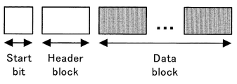
〈CECコマンドフレーム〉
図4にCECコマンドフレームを示し、図5にヘッダ部、図6にデータブロック部のフォーマットを示す。CECコマンドは最大長16×10ビットで、ヘッダ部は送信元および送信先を示すLogical Address、データ部は制御内容を示すオペコード、制御パラメータを示すオペランドから構成される。
<CEC command frame>
FIG. 4 shows a CEC command frame, FIG. 5 shows a header part, and FIG. 6 shows a data block part format. The CEC command has a maximum length of 16 × 10 bits, the header portion includes a logical address indicating a transmission source and a transmission destination, the data portion includes an operation code indicating control contents, and an operand indicating a control parameter.
〈システム動作〉
以上の構成において、映像表示システムの動作について説明する。
<System operation>
With the above configuration, the operation of the video display system will be described.
1.論理アドレス決定処理
まず、映像表示装置100に映像信号出力装置131〜135を接続してから、機器制御するためのLogical Addressが確定するまでの動作について図7、8を用いて説明する。図7は映像信号出力装置131〜135が行う処理のフローチャートであり、図8は映像表示装置100が行う処理のフローチャートである。
1. Logical Address Determination Processing First, operations from when the video
映像表示装置100に映像信号出力装置131を接続すると、映像信号出力装置131は5Vパワー信号を供給する(ステップS701)。
When the video
映像表示装置100は、5Vパワー信号の供給を検出すると(ステップS801)EDIDを初期化し、HPD信号をHighにする(ステップS802、S803)。
When the
映像信号出力装置131はHPD信号がHighになると(ステップS702)、EDIDを読み込み、表示装置の表示性能やHDMI接続端子位置を示すPhysical Addressを取得する(ステップS703)。
When the HPD signal becomes High (Step S702), the video
映像信号出力装置131は、Physical Addressが確定すると、デバイスタイプに対応付けられたLogical Addressを用いてPolling MessageをCECライン上に送信する(ステップS704)。ここでは、映像信号出力装置をカムコーダとすると、図15に従って送信元、送信先をいずれもLogical
Address「4」のPlayback Device1としてCECコマンドを送信する。
When the physical address is determined, the video
The CEC command is transmitted as the
Nack(No Acknowledgement)の場合(S705:NO)には、映像信号出力装置は自身を示すアドレスとしてそのLogical Addressを保持する(ステップS706)。 In the case of Nack (No Acknowledgment) (S705: NO), the video signal output apparatus holds the logical address as an address indicating itself (step S706).
Ack(Acknowledgement)信号が返ってきた場合にはそのアドレスは他の装置が使用済みであることが分かる。このとき、次のアドレスがある場合(S707:YES)には、そのアドレスにPolling Messageを送信する(ステップS708)。具体的には、上記のPlayback Device1をPlayback
Device2に変えて、送信元、送信先をLogical Address「6」とするCECコマンドを送信する。このように、機器種類に応じたLogical Addressに対して1つずつポーリングを実行することで、利用可能な(空いている)Logical Addressを探すことができる。
When an Ack (Acknowledgement) signal is returned, it is understood that the other device has used the address. At this time, if there is a next address (S707: YES), a polling message is transmitted to that address (step S708). Specifically, the above-mentioned
Instead of
一方、同一デバイスタイプを示す全てのLogical AddressにPolling Messageを送信してもアドレスが取得できない場合(S708:NO)は、Logical Addressに空きがないことが分かる。この場合は、映像信号出力装置は、不定アドレスを取得する。 On the other hand, if the address cannot be acquired even if the polling message is transmitted to all the logical addresses indicating the same device type (S708: NO), it is understood that there is no space in the logical address. In this case, the video signal output device acquires an indefinite address.
なお、上記のPolling Messageは、機器側から送信されるLogical Address取得要求と捉えることができる。そして、Nackを取得要求に対する許可応答、Ackを取得要求に対する否定応答と捉えることができる。 Note that the above-mentioned polling message can be regarded as a logical address acquisition request transmitted from the device side. Nack can be regarded as a permission response to the acquisition request, and Ack as a negative response to the acquisition request.
このようにして、映像信号出力装置131は機器制御ライン上でユニークに割り当てられるLogical Addressを取得する。
In this way, the video
ここで、Playback Device3まで送信してLogical Addressが確定できなかった場合、映像信号出力装置131は自身のアドレスを不定アドレスとしてLogical Address(14または15)を取得する。
Here, when the logical address cannot be determined by transmitting up to
一方、映像表示装置100は、CECライン上のPolling Messageを監視する(ステップS804)。接続された装置の端子位置およびLogical Addressが確定するまでの履歴を機器管理テーブルとしてメモリ部118に蓄積する(ステップS805)。
On the other hand, the
上記監視結果により、映像表示装置100は不定アドレスを取得した機器の本来取得する予定であったデバイスタイプを特定できる。
From the monitoring result, the
さらに、映像表示装置100は接続された装置のメーカコードやメニューへの表示名をCECライン経由で取得することも可能である。取得方法については映像表示装置100から映像信号出力装置131に対して問い合わせることも可能であるし、映像信号出力装置131から映像表示装置100に対して通知することも可能である。機器管理テーブル例を図9に示す。
Furthermore, the
図9の例では、機器管理テーブルとして、各デバイスの表示名と、Physical Address、Logical Address、Polling Messageの履歴とデバイスタイプが格納されている。ここでは、「DVDプレーヤ」、「ゲーム機」および「カメラ」は、Playback Deviceに対応したLogical Address(それぞれ、4,8,11)を取得できている。一方、「カムコーダ」は不定アドレス(Logical Address‘15’)を取得している。前者の3つの機器については、取得した論理アドレスからでもデバイスタイプを決定可能であるが、「カムコーダ」については取得した論理アドレスからデバイスタイプは特定できない。そこで、Polling Messageの履歴を参照すると、Playback Deviceに対応したアドレスの取得を行っていたこと分かるため、この機器のデバイスタイプを特定可能である。 In the example of FIG. 9, the device management table stores the display name of each device, the physical address, the logical address, and the polling message history and device type. Here, “DVD player”, “game machine”, and “camera” have acquired Logical Addresses (4, 8, and 11 respectively) corresponding to Playback Device. On the other hand, the “camcorder” has acquired an indefinite address (Logical Address '15'). For the former three devices, the device type can be determined from the acquired logical address, but for “camcorder”, the device type cannot be specified from the acquired logical address. Therefore, referring to the history of the polling message, it can be understood that the address corresponding to the playback device has been acquired, and thus the device type of this device can be specified.
2.論理アドレス再取得処理
次に、ユーザがリモコンボタンを押下してから、不定アドレス機器(Logical Address‘15’を取得している機器)に対してアドレスを再取得させるまでの動作について図10および図11を用いて説明する。
2. Logical Address Reacquisition Processing Next, the operation from when the user presses the remote control button until the indefinite address device (device that has acquired Logical Address '15') reacquires the address is shown in FIGS. 11 will be used for explanation.
ユーザは、まずリモコン1101の機器一覧ボタンを押下する。
The user first presses the device list button on the
映像表示装置100は、機器管理テーブルを参照し接続機器リスト1102を表示する(ステップS1001)。ここで、映像表示装置100は利用可能なLogical Addressを取得した機器だけでなく、機器制御に利用不可能な不定アドレスを取得した機器についてもリスト表示する。つまり、割り当てられているLogical Addressに関係なくリスト表示を行う。
The
接続機器リスト1102には、機器名が取得できた場合には機器名を表示し、機器名の取得できなかった機器についてはLogical Addressに応じたデバイスタイ
プを表示する。また、機器制御に利用不可能な不定アドレスを取得した機器については、Polling Messageの履歴を参照し、その履歴から特定できるデバイスタイプをリスト表示する。
In the
ユーザは、次にリモコン101を操作して接続機器リスト1102上のフォーカス1103を移動し、操作制御したい機器(本発明の第1の機器に相当)を選択する。
Next, the user operates the
映像表示装置100は、機器管理テーブルを参照し、選択された機器のLogical
Addressを確認する(ステップS1002)。ここで、選択された機器が不定アドレスの場合(ステップS1003)、映像表示装置100は該機器が本来取得予定であったデバイスタイプを特定する(ステップS1004)。
The
Address is confirmed (step S1002). If the selected device has an indefinite address (step S1003), the
そして、同一デバイスタイプを持ち、既に制御に利用可能なLogical Addressを取得している機器(本発明の第2の機器に相当)を電気的に切断する(ステップS1005)。この切断処理は、CECライン上に設けられたバススイッチ121〜125を制御部117が制御することで行える。なお、本実施形態においては、制御対象の機器と同一デバイスタイプの機器が複数存在するときは任意の機器を切断状態にする。
Then, a device (corresponding to the second device of the present invention) that has the same device type and has already acquired a logical address that can be used for control is electrically disconnected (step S1005). This disconnection process can be performed by the
なお、HPDをLowにすることにより該機器を切断状態にすることも可能である。その場合、該機器のHPDを一旦Low状態にし、操作制御したい機器から順にHPDをHighに切換える。このように処理することで操作制御したい機器に制御に利用可能なLogical Addressを取得させ、既に制御に利用可能なLogical Addressを取得していた機器に不定アドレスを取得させることができる。 It is also possible to put the device in a disconnected state by setting HPD to Low. In this case, the HPD of the device is temporarily set to the Low state, and the HPD is switched to High in order from the device whose operation is desired to be controlled. By performing processing in this way, it is possible to acquire a logical address that can be used for control by a device that is desired to be controlled, and to acquire an indefinite address from a device that has already acquired a logical address that can be used for control.
ただし、HPDをLowにしただけでは切断状態にならない機器も存在するので、本実施形態では、より確実のためバススイッチを用いてCECラインを完全に切断する構成としている。 However, since there is a device that cannot be disconnected only by setting HPD Low, in this embodiment, the CEC line is completely disconnected using a bus switch for more certainty.
続けて、映像表示装置100は、ユーザの選択した機器が接続される端子のHPDをLowにし、再度HPDをHighにしてアドレスの再取得処理を実行させる(ステップS1006)。
Subsequently, the
なお、この後、ステップS1005で切断された機器を、バススイッチによって接続状態にすることで不定アドレスを取得させることができる。 After that, the indefinite address can be acquired by setting the device disconnected in step S1005 to the connected state by the bus switch.
以上の処理により、制御対象としてユーザに指定された機器(第1の機器)に不定アドレスが割り当てられている場合でも、デバイスタイプに応じたLogical Addressを再取得させ、機器制御を行うことができるようになる。 Through the above processing, even when an indefinite address is assigned to a device (first device) designated by the user as a control target, it is possible to re-acquire the logical address according to the device type and perform device control. It becomes like this.
3.後処理
制御対象としてユーザに指定された機器に対する制御が終了した後は、Logical
Addressを元の状態に戻す後処理を行っても良いし、行わなくても良い。Logical Addressを元の状態に戻すか否かは、ユーザが決定できるようにしても良い。
3. Post-processing After the control for the device specified by the user as the control target is completed,
The post-processing for returning the address to the original state may or may not be performed. The user may be able to determine whether or not to restore the logical address to the original state.
Logical Addressを元の状態に戻す場合には、制御対象だった機器をCECライン上のバススイッチ、またはHPDにより制御終了後に切断し、切断していた機器(第2の機器)を接続状態にする。これにより、切断していた機器が元のLogical Addressを取得することになる。そして、制御対象の機器を接続状態にすることで、この機器が再び不定アドレスを取得することになる。制御対象としてユーザに指定された機器を一時的に制御したい場合は、このような後処理を行い、Logical Addressを元の状態に戻すのが望ましい。 When restoring the logical address to the original state, the control target device is disconnected by the bus switch on the CEC line or the HPD after the control is completed, and the disconnected device (second device) is set to the connection state. . As a result, the device that has been disconnected acquires the original Logical Address. Then, by setting the device to be controlled to the connected state, this device again acquires the indefinite address. When it is desired to temporarily control a device designated by the user as a control target, it is desirable to perform such post-processing and return the Logical Address to the original state.
また、Logical Addressを元の状態に戻さない場合には、機器管理テーブルを更新する。制御対象の機器のLogical Addressを不定アドレスから、取得したアドレスに書き換える。一方、ステップS1005で切断された機器(第2の機器)は不定アドレスを有することになるので、そのように機器管理テーブルを更新する。そして、以降の機器操作処理は、新しい機器管理テーブルに基づいて実行される。 Further, when the logical address is not returned to the original state, the device management table is updated. The logical address of the device to be controlled is rewritten from the indefinite address to the acquired address. On the other hand, since the device (second device) disconnected in step S1005 has an indefinite address, the device management table is updated as such. The subsequent device operation processing is executed based on the new device management table.
〈実施形態の作用・効果〉
以上の構成によれば、不定アドレスのデバイスタイプの特定が可能であり、同じデバイスタイプの機器をいったん退避(切断)することで、Logical Addressに空きを作り、不定アドレス機器の制御が可能となる。あらかじめ定められた上限数以上のデバイスが接続された場合でも、他の機器のユーザが切断したりすることなく制御可能であるので、ユーザの利便性が向上する。
<Operation and effect of the embodiment>
According to the above configuration, it is possible to specify the device type of the indefinite address, and by temporarily saving (disconnecting) the device of the same device type, a logical address is made free and the indefinite address device can be controlled. . Even when more than a predetermined upper limit number of devices are connected, control is possible without disconnecting by the user of another device, so that convenience for the user is improved.
このように不定アドレス機器もCEC制御可能となるため、機器が取得しているLogical Addressの種類に関係なく、制御可能な機器リストとして表示することができる。つまり、ユーザは機器の切断などを行う必要がないだけでなく、機器が不定アドレスを取得しているかなどを考慮する必要自体がなくなる。 In this way, CEC control is also possible for an indefinite address device, so that it can be displayed as a controllable device list regardless of the type of Logical Address acquired by the device. That is, not only does the user need not disconnect the device, but there is no need to consider whether the device has acquired an indefinite address.
(第2実施形態)
以下に、第2の実施形態に係る映像表示装置について説明する。
(Second Embodiment)
The video display apparatus according to the second embodiment will be described below.
第1の実施形態ではユーザから選択された機器と同じデバイスタイプを保持する任意の機器についてCECバスを切断した。第2の実施形態ではユーザの制御頻度に基づいて切断する機器を選択する構成とする。 In the first embodiment, the CEC bus is disconnected for any device that holds the same device type as the device selected by the user. In 2nd Embodiment, it is set as the structure which selects the apparatus cut | disconnected based on a user's control frequency.
図12は第2の実施形態における映像表示システムを示すブロック図である。なお、図において図1と同一または相当する構成要素については同一の符号を用い、その説明を省略する。 FIG. 12 is a block diagram showing a video display system in the second embodiment. In the figure, the same or corresponding components as in FIG. 1 are denoted by the same reference numerals, and the description thereof is omitted.
〈操作管理部〉
図12において操作管理部1201は、制御対象となる機器と、該機器に対する制御頻度を管理する。制御頻度には使用頻度と操作頻度が含まれる。使用頻度は、使用した累積時間に基づいて算出する。ここで、現在時刻に近ければ近いほど高い重み付けをして累積時間を算出することが好適である。操作頻度は機器を選択してから、その機器の操作を終了するまでのユーザのCEC制御による操作回数から求められる。単純化してCECコマンドの送信回数により算出することも可能である。
<Operation Management Department>
In FIG. 12, the
制御頻度を含む機器管理テーブル例を図13に示す。ここでは、使用頻度および操作頻度に加え、機器の動作状態も含む。 An example of the device management table including the control frequency is shown in FIG. Here, in addition to the use frequency and the operation frequency, the operation state of the device is also included.
〈論理アドレス再取得処理〉
次に、ユーザがリモコンボタンを押下してから、不定アドレス機器に対してアドレスを再取得させるまでの動作について図14を用いて説明する。
<Logical address reacquisition processing>
Next, the operation from when the user presses the remote control button until the address is reacquired by the indefinite address device will be described with reference to FIG.
ユーザは、まずリモコン101の機器一覧ボタンを押下する。
The user first presses the device list button on the
映像表示装置1200は、機器管理テーブルを参照し接続機器リスト1102を表示する(ステップS1401)。ここで、映像表示装置は制御可能なLogical Addressを取得した機器だけでなく、制御不可能な不定アドレスを取得した機器についてもリスト表示する。 The video display device 1200 refers to the device management table and displays the connected device list 1102 (step S1401). Here, the video display device displays not only a device that has acquired a controllable Logical Address but also a list of devices that have acquired an uncontrollable indefinite address.
ユーザは、次にリモコンを操作して接続機器リスト上のフォーカス1103を移動し、操作制御したい機器を選択する。
Next, the user operates the remote controller to move the
映像表示装置1200は、機器管理テーブルを参照し、選択された機器のLogica
l Addressを確認する(ステップS1402)。ここで、選択された機器が不定アドレスの場合、映像表示装置1200は該機器のデバイスタイプを特定する(ステップS1403、S1404)。
The video display device 1200 refers to the device management table and the Logica of the selected device
l Address is confirmed (step S1402). Here, when the selected device has an indefinite address, the video display device 1200 identifies the device type of the device (steps S1403 and S1404).
第2の実施形態では制御対象の機器と同じデバイスタイプの機器のうちから切断する機器を選択する(ステップS1405)。 In the second embodiment, a device to be disconnected is selected from devices of the same device type as the device to be controlled (step S1405).
具体的には、まず機器の動作状態を参照する(図13)。例えば、機器がPlayback Deviceで再生動作中の場合、2画面表示などでまだ操作制御する可能性があるので切断対象とはしない。また、機器がRecording Deviceで録画中など操作継続する可能性が高い場合も切断対象としない。一方、スタンバイ状態であれば切断候補機器とする。 Specifically, reference is first made to the operating state of the device (FIG. 13). For example, when the device is in playback operation using Playback Device, it may not be a disconnection target because there is a possibility that the operation may still be controlled by a two-screen display or the like. In addition, even when the device is highly likely to continue the operation such as recording in Recording Device, the device is not targeted for disconnection. On the other hand, if it is in a standby state, it is determined as a disconnection candidate device.
次に、切断候補機器が複数存在する場合、使用頻度、操作頻度を参照する。ここでは、使用頻度および操作頻度が低いものを切断対象とする。本実施例では操作頻度、使用頻度の順で参照することとする。これは、CECによる操作頻度の高いものを残しておくほうがユーザの使い勝手を損なわないためである。 Next, when there are a plurality of disconnection candidate devices, the use frequency and operation frequency are referred to. Here, a cutting object having a low use frequency and low operation frequency is set as a cutting target. In this embodiment, reference is made in the order of operation frequency and use frequency. This is because the user-friendliness is not impaired by leaving the one with a high operation frequency by CEC.
なお、使用頻度および操作頻度が同じ場合は、ユーザが選択した機器を制御することを第1優先に、第1の実施例同様任意の機器を切断するものとする。 If the use frequency and the operation frequency are the same, the control of the device selected by the user is given priority to disconnect any device as in the first embodiment.
以上の判断により切断対象となった機器を電気的に切断する(ステップS1406)。 The device to be disconnected by the above determination is electrically disconnected (step S1406).
続いて、映像表示装置は、ユーザの選択した機器が接続される端子のHPDをLowにし、再度HPDをHighにしてアドレスの再取得処理を実行させる(ステップS1407)。 Subsequently, the video display apparatus sets the HPD of the terminal to which the device selected by the user is connected to Low, sets HPD to High again, and executes address reacquisition processing (step S1407).
なお、映像信号出力装置からの映像信号入力停止、もしくは挿抜や電源オン/オフにより5Vパワー供給が停止した場合、映像表示装置はCECバスの電気的な切断を解除し、切断していた機器に対してアドレスの再取得処理を実行する。 When the video signal input from the video signal output device is stopped, or when the 5V power supply is stopped due to insertion / extraction or power on / off, the video display device cancels the electrical disconnection of the CEC bus and replaces the disconnected device. Address re-acquisition processing is executed.
以上の構成によれば、不定アドレスのデバイスタイプの特定が可能であり、同じデバイスタイプの機器をいったん退避(切断)することで、Logical Addressに空きを作り、不定アドレス機器の制御が可能となる。あらかじめ定められた上限数以上のデバイスが接続された場合でも、他の機器のユーザが切断したりすることなく制御可能であるので、ユーザの利便性が向上する。 According to the above configuration, it is possible to specify the device type of the indefinite address, and by temporarily saving (disconnecting) the device of the same device type, a logical address is made free and the indefinite address device can be controlled. . Even when more than a predetermined upper limit number of devices are connected, control is possible without disconnecting by the user of another device, so that convenience for the user is improved.
さらに、使用頻度や操作頻度に基づいて切断する機器を判断するため、ユーザが利用する可能性の低い機器が切断されるので、ユーザの利便性を損なうことがない。 Furthermore, since the device to be disconnected is determined based on the use frequency and the operation frequency, the device that is unlikely to be used by the user is disconnected, so that the convenience of the user is not impaired.
また、電気的に切断した機器についても、不定アドレス機器の使用を終了する際にアドレスの再取得処理をさせることで、次に使用する場合の利便性を確保することが可能となる。 In addition, even when the device is electrically disconnected, it is possible to ensure the convenience of the next use by performing the address reacquisition process when the use of the indefinite address device is terminated.
(その他)
上記の例では、Playback Device(再生装置)であるカムコーダを例に説明したが、録画装置やチューナなどの他の種類の機器についても、同様にアドレスの割当を行うことで、機器制御を行うことが可能になる。
(Other)
In the above example, a camcorder, which is a playback device, has been described as an example. However, for other types of devices such as a recording device and a tuner, device control is performed by assigning addresses in the same manner. Is possible.
また、上記の例ではHDMIシステムを例に説明したが、上記の技術はHDMIシステ
ムに限定して適用されるものではなく、同様のシステムに対しても適用可能であることは容易に理解できよう。
In the above example, the HDMI system has been described as an example. However, it can be easily understood that the above technique is not limited to the HDMI system and can be applied to a similar system. .
100 映像表示装置
110 HDMI受信部
113 映像表示部
117 制御部
118 メモリ部
121〜125 バススイッチ
204 HDMI送信部
304 5Vライン
305 HPDライン
306 CECライン
307 DDCライン
DESCRIPTION OF
Claims (14)
HDMI規格に対応する通信を前記第1の機器のデバイスタイプと一致するデバイスタイプである第2の機器と行うために前記第2の機器と前記機器制御装置とを接続する第2の接続手段と、
前記第1の機器と前記機器制御装置とが接続されている場合であって、かつ、前記第2の機器と前記機器制御装置とが接続されている場合に、前記第1の機器が前記第1の機器のデバイスタイプに対応する論理アドレスと異なる論理アドレスを取得しているとき、前記第2の機器が取得している論理アドレスを前記第1の機器に取得させるために、前記第2の機器と前記機器制御装置との通信を切断するように前記第2の接続手段を制御し、前記第1の機器のデバイスタイプに対応する論理アドレスを前記第1の機器に取得させるための処理を行う制御手段と
を有することを特徴とする機器制御装置。 A first control unit that connects the first device and the device control device to perform communication corresponding to the High Definition Multimedia Interface (HDMI) standard with the first device;
Second connection means for connecting the second device and the device control device to perform communication corresponding to the HDMI standard with a second device having a device type that matches the device type of the first device; ,
In a case where said first device and the device control apparatus is connected, and, in case that the previous SL second device and the device control apparatus is connected, the first device when trying to get the logical address different from the logical address corresponding to the device type of the first device, in order to acquire a logical address to which the second device is getting the first device, the first For controlling the second connecting means to disconnect communication between the second device and the device control apparatus, and causing the first device to acquire a logical address corresponding to a device type of the first device. device control apparatus characterized by having a <br/> and control means for processing.
るための処理は、前記第1の機器に対応するHPD(Hot Plug Detect)をローからハイに変更する処理を含むことを特徴とする請求項1から5のいずれか1項に記載の機器制御装置。 Causing the first device to obtain a logical address corresponding to the device type of the first device.
Process because the device control according to any one of claims 1 to 5, characterized in that it comprises a process of changing from low to HPD (Hot Plug Detect) corresponding to the first device to the high apparatus.
前記第1の機器と前記機器制御装置とが接続されている場合であって、かつ、前記第2の機器と前記機器制御装置とが接続されている場合に、前記第1の機器が前記第1の機器のデバイスタイプに対応する論理アドレスと異なる論理アドレスを取得しているとき、前記第2の機器が取得している論理アドレスを前記第1の機器に取得させるために、前記第2の機器と前記機器制御装置との通信を切断するように前記第2の接続手段を制御し、前記第1の機器のデバイスタイプに対応する論理アドレスを前記第1の機器に取得させるための処理を行うステップを有することを特徴とする制御方法。 First connection means for connecting the first device to perform communication corresponding to the HDMI (High Definition Multimedia Interface) standard with the first device, and communication corresponding to the HDMI standard for the device of the first device A control method for controlling a device control apparatus having a second device that is a device type that matches a type and a second connection means for connecting the second device to perform,
A case where the first device and the device control apparatus and is Ru connected Tei and before SL when the second device and the device control apparatus and is Ru connected Tei, the first device is the when trying to get the logical address different from the logical address corresponding to the device type of the first device, in order to acquire a logical address to which the second device is getting the first device, the second Processing for controlling the second connection means to disconnect communication between the device and the device control apparatus, and causing the first device to acquire a logical address corresponding to the device type of the first device A control method comprising the steps of:
Priority Applications (4)
| Application Number | Priority Date | Filing Date | Title |
|---|---|---|---|
| JP2008138344A JP5230267B2 (en) | 2008-05-27 | 2008-05-27 | Device control apparatus and control method |
| CN200980119566.3A CN102047613B (en) | 2008-05-27 | 2009-05-18 | Device control apparatus and device control method in video image display system including a plurality of connected devices |
| US12/990,304 US8255579B2 (en) | 2008-05-27 | 2009-05-18 | Device control apparatus and device control method in video image display system including a plurality of connected devices |
| PCT/JP2009/059468 WO2009145121A1 (en) | 2008-05-27 | 2009-05-18 | Device control apparatus and device control method in video image display system including a plurality of connected devices |
Applications Claiming Priority (1)
| Application Number | Priority Date | Filing Date | Title |
|---|---|---|---|
| JP2008138344A JP5230267B2 (en) | 2008-05-27 | 2008-05-27 | Device control apparatus and control method |
Publications (3)
| Publication Number | Publication Date |
|---|---|
| JP2009290322A JP2009290322A (en) | 2009-12-10 |
| JP2009290322A5 JP2009290322A5 (en) | 2011-07-07 |
| JP5230267B2 true JP5230267B2 (en) | 2013-07-10 |
Family
ID=41055276
Family Applications (1)
| Application Number | Title | Priority Date | Filing Date |
|---|---|---|---|
| JP2008138344A Active JP5230267B2 (en) | 2008-05-27 | 2008-05-27 | Device control apparatus and control method |
Country Status (4)
| Country | Link |
|---|---|
| US (1) | US8255579B2 (en) |
| JP (1) | JP5230267B2 (en) |
| CN (1) | CN102047613B (en) |
| WO (1) | WO2009145121A1 (en) |
Families Citing this family (19)
| Publication number | Priority date | Publication date | Assignee | Title |
|---|---|---|---|---|
| JP2010118806A (en) * | 2008-11-12 | 2010-05-27 | Sony Corp | Information processing device and method, program, and recording medium |
| JP5574695B2 (en) * | 2009-12-21 | 2014-08-20 | キヤノン株式会社 | Communication device |
| JP5150653B2 (en) * | 2010-01-08 | 2013-02-20 | 株式会社東芝 | Video / audio processing apparatus and video / audio processing method |
| JP5159801B2 (en) * | 2010-01-12 | 2013-03-13 | 株式会社東芝 | Video / audio processing apparatus and video / audio processing method |
| JP5434630B2 (en) * | 2010-01-27 | 2014-03-05 | 船井電機株式会社 | Electronics |
| WO2011105259A1 (en) * | 2010-02-24 | 2011-09-01 | オリンパスメディカルシステムズ株式会社 | Medical device system |
| JP5590377B2 (en) * | 2010-02-24 | 2014-09-17 | ソニー株式会社 | COMMUNICATION DEVICE, COMMUNICATION CONTROL METHOD, AND PROGRAM |
| JP2012029070A (en) * | 2010-07-23 | 2012-02-09 | Sony Corp | Repeater and control method |
| JP5267533B2 (en) * | 2010-10-05 | 2013-08-21 | 船井電機株式会社 | RECORDING DEVICE, NETWORK SYSTEM, AND METHOD FOR OBTAINING LOGICAL ADDRESS BY RECORDING DEVICE |
| EP2649790A1 (en) * | 2010-12-09 | 2013-10-16 | Thomson Licensing | Method and apparatus for interrupting hdmi cec broadcast messages |
| JP2013055386A (en) * | 2011-09-01 | 2013-03-21 | Canon Inc | Electronic apparatus |
| JP6004628B2 (en) * | 2011-10-19 | 2016-10-12 | キヤノン株式会社 | Electronics |
| CN103259999B (en) * | 2012-02-20 | 2016-06-15 | 联发科技(新加坡)私人有限公司 | HPD signal output control method, HDMI receiving device and system |
| JP5458165B2 (en) * | 2012-11-22 | 2014-04-02 | 株式会社東芝 | Video / audio processing apparatus and video / audio processing method |
| JP6465541B2 (en) * | 2013-08-06 | 2019-02-06 | キヤノン株式会社 | COMMUNICATION DEVICE, REPRODUCTION DEVICE, ITS METHOD, AND PROGRAM |
| US8935433B1 (en) * | 2013-10-15 | 2015-01-13 | Sony Corporation | Connection of more than three playback devices to HDMI CEC link |
| CN111445844B (en) * | 2019-01-17 | 2021-09-21 | 奇景光电股份有限公司 | Cumulative brightness compensation system and organic light emitting diode display |
| CN110430451B (en) * | 2019-08-20 | 2021-09-10 | 北京豆萌信息技术有限公司 | Video playing method, player, server and system |
| CN114631326B (en) * | 2019-11-12 | 2024-07-09 | 索尼集团公司 | Information processing apparatus, information processing method, information processing program, terminal apparatus, and method and program for controlling terminal apparatus |
Family Cites Families (15)
| Publication number | Priority date | Publication date | Assignee | Title |
|---|---|---|---|---|
| JP2002051232A (en) | 2000-08-04 | 2002-02-15 | Canon Inc | Receiver, remote controller, receiving system and device to be controlled |
| US7886332B2 (en) | 2002-03-19 | 2011-02-08 | Canon Kabushiki Kaisha | Television broadcast receiving apparatus |
| JP4408677B2 (en) | 2002-11-29 | 2010-02-03 | キヤノン株式会社 | Receiving apparatus and receiving method |
| JP4298282B2 (en) | 2002-12-13 | 2009-07-15 | キヤノン株式会社 | Display control apparatus and control method thereof |
| JP4497944B2 (en) | 2003-02-05 | 2010-07-07 | キヤノン株式会社 | Receiving apparatus and control method of receiving apparatus |
| JP4458832B2 (en) | 2003-12-05 | 2010-04-28 | キヤノン株式会社 | Program extracting apparatus and control method thereof |
| JP4617167B2 (en) | 2004-02-04 | 2011-01-19 | キヤノン株式会社 | Broadcast receiving apparatus and control method thereof |
| JP4769513B2 (en) | 2005-08-15 | 2011-09-07 | キヤノン株式会社 | Reproduction control method and reproduction control apparatus |
| JP2007078980A (en) | 2005-09-13 | 2007-03-29 | Funai Electric Co Ltd | Image display system |
| JP4565651B2 (en) | 2006-02-13 | 2010-10-20 | キヤノン株式会社 | Image processing apparatus and image processing method |
| WO2008020401A2 (en) * | 2006-08-18 | 2008-02-21 | Koninklijke Philips Electronics N.V. | Decoupled connections |
| KR100855467B1 (en) * | 2006-09-27 | 2008-09-01 | 삼성전자주식회사 | Apparatus and method for mapping of nonvolatile non-volatile memory supporting separated cell type |
| KR20080058740A (en) * | 2006-12-22 | 2008-06-26 | 삼성전자주식회사 | Digital broadcasting receive apparatus and method for syncronization thereof |
| JP2009004877A (en) | 2007-06-19 | 2009-01-08 | Toshiba Corp | Data transmission device and data transmission method |
| KR20090018471A (en) * | 2007-08-17 | 2009-02-20 | 삼성전자주식회사 | Display apparatus and control method of the same |
-
2008
- 2008-05-27 JP JP2008138344A patent/JP5230267B2/en active Active
-
2009
- 2009-05-18 WO PCT/JP2009/059468 patent/WO2009145121A1/en active Application Filing
- 2009-05-18 US US12/990,304 patent/US8255579B2/en not_active Expired - Fee Related
- 2009-05-18 CN CN200980119566.3A patent/CN102047613B/en not_active Expired - Fee Related
Also Published As
| Publication number | Publication date |
|---|---|
| JP2009290322A (en) | 2009-12-10 |
| WO2009145121A1 (en) | 2009-12-03 |
| CN102047613A (en) | 2011-05-04 |
| US8255579B2 (en) | 2012-08-28 |
| US20110066759A1 (en) | 2011-03-17 |
| WO2009145121A4 (en) | 2010-01-21 |
| CN102047613B (en) | 2014-05-21 |
Similar Documents
| Publication | Publication Date | Title |
|---|---|---|
| JP5230267B2 (en) | Device control apparatus and control method | |
| JP4968091B2 (en) | Electronic device, message response method and program | |
| EP2607988B1 (en) | Transmission device, power supply switching method, reception device | |
| US9942605B2 (en) | Devices and methods for transmitting and receiving data of a sink device to change video display resolution based on error counter value detected at the sink device using HDMI | |
| US8698956B2 (en) | Transmitting device, receiving device, and method for transmitting operational information in receiving device | |
| US8525691B2 (en) | Electric equipment with digital interface and method for controlling the same | |
| US10474241B2 (en) | Method and device for transmitting/receiving data using HDMI | |
| US9305516B1 (en) | Electronic device | |
| KR20110042109A (en) | Video control apparatus and control method for video control apparatus | |
| JP2008067024A (en) | Display device and display system | |
| US20080016528A1 (en) | Information-processing device, information-processing method, and computer program | |
| US20100141845A1 (en) | Audio output device connectable with plurality of devices and method of controlling the same | |
| US10162769B2 (en) | Method and apparatus for transmitting and receiving data using HDMI | |
| EP2819404A1 (en) | Video processing system, and video processing method | |
| JP4917452B2 (en) | Display device and display system | |
| CN114830677A (en) | Receiving apparatus, method for controlling the same, and transmitting/receiving system | |
| US20190387183A1 (en) | Audio/video output device | |
| KR20090038660A (en) | Media sink device and method for controlling of the same | |
| JP5618534B2 (en) | Communication device | |
| KR101111648B1 (en) | Digital video apparatus and its in-put selection menu setting method | |
| JP2008219544A (en) | Display device | |
| KR20240029322A (en) | Sink device, source device and method thereof | |
| KR100677235B1 (en) | DISPLAY METHOD FOR CAPTION DATA BASED ON DTVLink |
Legal Events
| Date | Code | Title | Description |
|---|---|---|---|
| A521 | Request for written amendment filed |
Free format text: JAPANESE INTERMEDIATE CODE: A523 Effective date: 20110524 |
|
| A621 | Written request for application examination |
Free format text: JAPANESE INTERMEDIATE CODE: A621 Effective date: 20110524 |
|
| A131 | Notification of reasons for refusal |
Free format text: JAPANESE INTERMEDIATE CODE: A131 Effective date: 20121204 |
|
| A521 | Request for written amendment filed |
Free format text: JAPANESE INTERMEDIATE CODE: A523 Effective date: 20130131 |
|
| TRDD | Decision of grant or rejection written | ||
| A01 | Written decision to grant a patent or to grant a registration (utility model) |
Free format text: JAPANESE INTERMEDIATE CODE: A01 Effective date: 20130219 |
|
| A61 | First payment of annual fees (during grant procedure) |
Free format text: JAPANESE INTERMEDIATE CODE: A61 Effective date: 20130319 |
|
| FPAY | Renewal fee payment (event date is renewal date of database) |
Free format text: PAYMENT UNTIL: 20160329 Year of fee payment: 3 |