JP5228516B2 - Tempo perception device - Google Patents
Tempo perception device Download PDFInfo
- Publication number
- JP5228516B2 JP5228516B2 JP2008031936A JP2008031936A JP5228516B2 JP 5228516 B2 JP5228516 B2 JP 5228516B2 JP 2008031936 A JP2008031936 A JP 2008031936A JP 2008031936 A JP2008031936 A JP 2008031936A JP 5228516 B2 JP5228516 B2 JP 5228516B2
- Authority
- JP
- Japan
- Prior art keywords
- tempo
- pedal
- drive signal
- time
- reaction force
- Prior art date
- Legal status (The legal status is an assumption and is not a legal conclusion. Google has not performed a legal analysis and makes no representation as to the accuracy of the status listed.)
- Expired - Fee Related
Links
Images


Landscapes
- Electrophonic Musical Instruments (AREA)
- Auxiliary Devices For Music (AREA)
Description
本発明は、鍵盤楽器等のペダルを通じて奏者にテンポを知覚させるテンポ知覚装置に関する。 The present invention relates to a tempo perception device that allows a player to perceive a tempo through a pedal such as a keyboard instrument.
楽器の演奏において、通常、演奏の時間的基準となるものが必要であるため、従来、メトロノーム等を用いてテンポを合わせることが行われる。また、テンポを知らせるクリック音等を発生させるメトロノーム機能等が楽器自体に備えられたものもある。 In the performance of musical instruments, since a time standard for performance is usually required, the tempo is conventionally adjusted using a metronome or the like. Some instruments have a metronome function for generating a click sound for informing the tempo.
ところで、鍵盤楽器の鍵に関しては、下記特許文献1の電子楽器に示されるように、ソレノイド等のアクチュエータで、押鍵される鍵に対して与える力覚を制御し、生ピアノに近い押鍵感触を目指したものが知られている。
しかしながら、テンポをメトロノーム機能を用いて知覚させる場合は、クリック音等が一種の雑音となり、演奏の邪魔になることがある。 However, when the tempo is perceived using the metronome function, the click sound or the like becomes a kind of noise, which may interfere with performance.
また、上記特許文献1では、鍵に力覚が付与されるが、演奏のテンポを知覚させる機能は有しない。特に、上記特許文献1では手鍵盤を想定している。そのため、例えば、鍵に振動を与えることで、テンポを知覚させるようなことを考えたとしても、演奏の邪魔になるだけであり、場合によっては、ノイズ発生となる可能性もあり、製品として採用されることは考えにくい。
Further, in
本発明は上記従来技術の問題を解決するためになされたものであり、その目的は、ペダルを通じて奏者に触覚でテンポを知覚させることができるテンポ知覚装置を提供することにある。 The present invention has been made to solve the above-described problems of the prior art, and an object of the present invention is to provide a tempo perception device that allows a player to perceive a tempo through a pedal.
上記目的を達成するために本発明の請求項1のテンポ知覚装置は、楽器のペダル(22)を通じて奏者にテンポを知覚させるテンポ知覚装置であって、テンポを設定するテンポ設定手段(17)と、前記テンポ設定手段により設定されたテンポに同期して、駆動信号を生成して出力する駆動信号生成出力手段(11、15)と、前記駆動信号生成出力手段により出力される駆動信号によって動作し、前記ペダルに対して奏者が触覚で感じるように力覚を付与する力覚付与手段(30)と、前記力覚付与手段によって付与される力覚の時間幅をユーザの指示に従って予め設定すると共に、前記ペダルが変位しているか静止しているかにかかわらず、時間進行に応じて山なりとなって前記時間幅における途中に強さのピークが生じる山形の波形となるように、前記力覚の波形を設定する波形設定手段とを有することを特徴とする。
In order to achieve the above object, a tempo perception apparatus according to
好ましくは、拍子を決定する拍子決定手段(17)を有し、前記駆動信号生成出力手段は、前記拍子決定手段により決定された拍子と前記テンポ設定手段により設定されたテンポとから規定される拍タイミングに合わせて前記駆動信号を生成及び出力する(請求項2)。 Preferably, there is a time signature determining means (17) for determining a time signature, wherein the drive signal generating / outputting means is a beat defined by the time determined by the time signature determining means and the tempo set by the tempo setting means. The drive signal is generated and output in accordance with the timing (claim 2).
好ましくは、自動演奏データを読み出す読み出し手段(11)を有し、前記拍子決定手段により決定される拍子は、前記読み出し手段により読み出された自動演奏データで規定される(請求項3)。 Preferably, it has a reading means (11) for reading automatic performance data, and the time signature determined by the time signature determining means is defined by the automatic performance data read by the reading means (claim 3).
好ましくは、前記拍子決定手段により決定される拍子は、ユーザにより指定される(請求項4)。 Preferably, the time determined by the time determining means is specified by the user.
好ましくは、前記力覚付与手段は、前記駆動信号に応じた電流が流されるソレノイドコイル(32)と、前記ペダルに対して固定状態にされたプランジャ(35)とを備えるソレノイドであり、さらに、前記プランジャの位置を検出する位置検出手段(42)を有し、前記駆動信号生成出力手段は、前記ソレノイドコイルに流すべき電流値が前記位置検出手段により検出された前記プランジャの位置に応じた値となるように、前記駆動信号を生成する(請求項5)。 Preferably, the force sense applying means is a solenoid including a solenoid coil (32) through which a current corresponding to the drive signal flows, and a plunger (35) fixed to the pedal, It has position detection means (42) for detecting the position of the plunger, and the drive signal generation output means is a value corresponding to the position of the plunger at which the current value to be passed through the solenoid coil is detected by the position detection means. The drive signal is generated so as to satisfy (Claim 5).
好ましくは、前記力覚付与手段によって付与される力覚の時間幅を設定する時間幅設定手段(17)を有する(請求項6)。 Preferably, it has time width setting means (17) for setting a time width of the force sense given by the force sense giving means.
好ましくは、前記力覚付与手段によって付与される力覚の強さを設定する強さ設定手段(17)を有する(請求項7)。 Preferably, the apparatus has strength setting means (17) for setting the strength of the force sense given by the force sense giving means.
なお、上記括弧内の符号は例示である。 In addition, the code | symbol in the said parenthesis is an illustration.
本発明の請求項1によれば、ペダルを通じて奏者に触覚でテンポを知覚させることができる。 According to the first aspect of the present invention, the player can perceive the tempo through the pedal.
請求項2によれば、拍タイミングを知覚させることができる。 According to claim 2, the beat timing can be perceived.
請求項3によれば、自動演奏データの曲の演奏練習に役立てることができる。 According to the third aspect, it can be used for practice of music performance of automatic performance data.
請求項4によれば、奏者の希望する拍子での演奏練習に役立てることができる。 According to the fourth aspect, it is possible to use it for performance practice at a time signature desired by the player.
請求項5によれば、ソレノイドに、ペダルの踏み込み深さに応じた駆動力を発揮させ、例えば、ペダルの踏み込み深さによらず一定の強さの力覚を付与することができる。 According to the fifth aspect of the invention, the solenoid can exhibit a driving force according to the depth of depression of the pedal, and for example, a force sense having a constant strength can be given regardless of the depth of depression of the pedal.
請求項6によれば、力覚を奏者の所望の感度に調節することができる。 According to the sixth aspect, the sense of force can be adjusted to the player's desired sensitivity.
請求項7によれば、力覚を奏者の所望の感度に調節することができる。 According to the seventh aspect, the sense of force can be adjusted to the player's desired sensitivity.
以下、本発明の実施の形態を図面を参照して説明する。 Hereinafter, embodiments of the present invention will be described with reference to the drawings.
図1は、本発明の一実施の形態に係るテンポ知覚装置が適用される電子鍵盤楽器の全体構成を示すブロック図である。図2は、テンポ知覚装置の要部の断面図である。 FIG. 1 is a block diagram showing an overall configuration of an electronic keyboard instrument to which a tempo perception device according to an embodiment of the present invention is applied. FIG. 2 is a cross-sectional view of a main part of the tempo sensing device.
本鍵盤楽器は、図1に示すように、タイマ12、記憶部13、各種インターフェイス14、ソレノイド駆動部15、演奏操作部16、設定操作部17、表示部18、楽音発生部19及び位置センサ42が、バス10を介してCPU11にそれぞれ接続されて構成される。
As shown in FIG. 1, the keyboard instrument includes a
演奏操作部16には、音高情報を入力するための不図示の鍵盤、各種演奏操作子、及び足で演奏操作するためのペダル22(図2参照)が含まれる。設定操作部17には、各種情報を入力するための複数の各種スイッチ(図示せず)が含まれる。表示部18は、楽譜や文字等の各種情報を表示する。楽音発生部19は、それぞれ図示しない音源回路、効果回路、サウンドシステムを含み、演奏操作部16で入力された演奏データや予め設定された演奏データ等を楽音信号(演奏信号)に変換し、各種効果を付与して音響に変換する。
The
CPU11は、本テンポ知覚装置を含む電子鍵盤楽器全体の制御を司る。記憶部13には、CPU11が実行する制御プログラムや各種テーブルデータ等を記憶するROMのほか、演奏データ、テキストデータ等の各種入力情報、各種フラグやバッファデータ及び演算結果等を一時的に記憶するRAM等が含まれる。記憶部13には、後述するduty比マップ21も記憶されている。タイマ12は、タイマ割り込み処理における割り込み時間等の各種時間を計時する。各種インターフェイス14には、MIDI(Musical Instrument Digital Interface)I/F、有線または無線の通信I/F等が含まれる。
The
テンポ知覚装置のメカ機構は、図2に示すように、鍵盤楽器本体20とペダル22との間に介在して配設される。ペダル22は下方に踏み込み操作される。同図において、初期状態である非踏み込み状態を実線で示し、踏み込み状態を2点鎖線で示している。ペダル22は、例えば、ダンパペダルとして機能するペダルである。
As shown in FIG. 2, the mechanical mechanism of the tempo perception device is disposed between the
テンポ知覚装置のメカ機構は、主に、鍵盤楽器本体20の下部(例えば、不図示の棚板の下面)に設けられるペダルボックス40内に構成されるが、配設箇所は問わず、ペダル22に対して力覚を付与できるような部位に配置されればよい。ここで、本実施の形態では、ペダル22に付与する力覚は、一例として、ペダル22に対して踏み込みに抗する力(反力)を付与するものとする。特に、いずれの踏み込み深さにおいても、ペダル22に対して初期状態に戻す方向に反力が作用するように構成する。
The mechanical mechanism of the tempo perception device is mainly configured in the
ペダル22は、支点23にて先端(図2の左端)が上下に揺動自在にされている。ペダル22の後端部に設けられた回動軸25を介して、鉛直方向に延びたロッド26が連結され、ペダル22の踏み込み操作に連動して、ロッド26が上下移動するようになっている。ペダル22の後端部の下方には、ペダル22の後端部と当接してペダル22の非踏み込み位置を規制するストッパ24が設けられている。
The front end of the pedal 22 (left end in FIG. 2) is swingable up and down at a
ペダルボックス40内において、固定部41の上に、ソレノイド本体30が配設固定される。ソレノイド本体30において、ボビン31の内側に、プランジャ35が上下方向に移動自在に配設され、ボビン31の周りにソレノイドコイル32が巻回され、上下にヨーク33、34が配設される。プランジャ35は、ロッド26の上端に連結固定されており、ペダル22に連動して上下動するようになっている。なお、プランジャ35は、ペダル22に対して連動して動作するように構成されればよく、ロッド26に対して直接または間接に固定状態にされるかを問わない。
In the
固定部41の下方には、バネ受け部37が設けられ、バネ受け部37と固定部41の下部とに復帰用のコイルバネ36が接続されている。コイルバネ36は圧縮状態で介装されており、ペダル22の後端部を常に下方に付勢している。そのため、ペダル22の非踏み込み状態においては、ペダル22の後端部が下方に付勢されて、ストッパ24に当接している。
A
ペダルボックス40内において、ロッド26の上下方向の位置を検出する位置センサ42が設けられている。位置センサ42は、例えば、ロッド26の位置を光学的に検出するものであるが、その検出信号は、ペダル22の踏み込み方向における位置を示すものでもあるし、プランジャ35の上下方向の位置を示すものでもある。なお、プランジャ35の上下方向の位置を検出できるものであれば、位置センサ42の構成(フォトリフレクタ型やフォトインタラプタ型等の光学式、接触式、磁気式等)や配設位置は問わない。ただし、プランジャ35に近接して設ける場合は、ソレノイドコイル32の影響を考慮し、磁気式は避けるのがよい。
A
ソレノイド駆動部15(図1参照)は、CPU11による制御に従って、駆動信号をソレノイド本体30に供給する。それによって、プランジャ35が下方に付勢され、ロッド26を介してペダル22に踏み込みに抗する方向に力を与える。上記駆動信号は、ソレノイド本体30のソレノイドコイル32に流すべき電流の目標値に応じたduty(デューティ)比(%)となるようにパルス幅変調を施したPWM信号である。
The solenoid drive unit 15 (see FIG. 1) supplies a drive signal to the
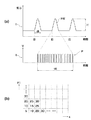
図3(a)は、ソレノイド本体30によりペダル22に対して与えられる反力の推移の一例を示す波形(I)と、1つの波形に対応するduty波形を示した図(II)である。本実施の形態では、同図(a)に示すように、力覚として、拍タイミング毎に、パルス状に反力が与えられる。1回の反力については、拍タイミングの時点で反力が立ち上がり、反力強さHをピークとして、反力時間幅tBが経過すると反力が0となる。1つの反力波形を「FW」で表す。
FIG. 3A is a waveform (I) showing an example of the transition of the reaction force applied to the pedal 22 by the
この反力波形FWを、図3(a)のIに示すように、矩形波ではなくやや山形にしたのは、足への刺激がきつすぎないようにするためと、反力強さHを強くした場合でもテンポ知覚装置から大きなノイズが発生しにくくするためである。1つの反力波形FWを出力するために、図3(a)のIIに示すようなPWM波形Pで駆動するのがよい。PWM波形Pの図(II)において、縦軸は、電圧(または電流でもよい)で、横軸が時間である。 The reaction force waveform FW, as indicated by I in FIG. 3 (a), is not a rectangular wave, but rather a mountain shape. This is because the reaction force strength H is set so that the stimulation to the foot is not too tight. This is to prevent a large amount of noise from being generated from the tempo perception device even when the strength is increased. In order to output one reaction force waveform FW, it is preferable to drive with a PWM waveform P as indicated by II in FIG. In the diagram (II) of the PWM waveform P, the vertical axis is voltage (or current), and the horizontal axis is time.
このPWM波形Pは、拍の先頭タイミングではduty比が小さく、徐々に大きくなって、次の拍の先頭タイミングとの真ん中で最大となり、その後、徐々に小さくなっていく。反力時間幅tB内のdutyの波の数は任意であり、例えば、8〜1000としてもよい。 The PWM waveform P has a small duty ratio at the beginning timing of the beat and gradually increases, reaches the maximum in the middle of the beginning timing of the next beat, and then gradually decreases. The number of duty waves within the reaction force time width tB is arbitrary, and may be, for example, 8 to 1000.
図3(b)は、duty比マップ21(図1参照)の一例を示す概念図である。このduty比マップ21は、プランジャ35の移動量xと反力強さ指示値F1とに対して、駆動信号のduty比を対応付けたものである。移動量xは、位置センサ42の検出信号から把握される、プランジャ35の初期位置からの上方への変位量である。反力強さ指示値F1は、反力強さHを決定するためのパラメータであり、設定操作部17を介してユーザによって指定される。
FIG. 3B is a conceptual diagram showing an example of the duty ratio map 21 (see FIG. 1). The
例えば、図3(b)中の「30」という値は、所定の基準値(例えば、100)に対する比率(%)である。図3(a)のIIでは、複雑な制御を例示したが、仮に単純に、反力時間幅tB内に1つのduty波形しかないような場合を考えると、「30」という値に対して「5」という値は、1/6の幅のduty波形、すなわち、「30」より1/6細かいパルスで制御することを意味する。
For example, the value “30” in FIG. 3B is a ratio (%) to a predetermined reference value (for example, 100). In FIG. 3 (a) II, complicated control is exemplified. However, simply considering a case where there is only one duty waveform within the reaction force time width tB, the value "30" A value of “5” means that control is performed with a duty waveform having a width of 1/6, that is, a
図3(a)のIIのような、duty比が徐々に変化するような制御も含めて考えれば、「30」という値は、反力時間幅tBに対するオン時間の集合が100に対して「30」であることを意味し、「5」であれば、「30」の1/6の細かいパルス群(時間とともに変化するモードは同じ)で制御されることになる。 Considering the control such as II in FIG. 3A in which the duty ratio is gradually changed, the value of “30” indicates that the set of on-time with respect to the reaction force time width tB is “100”. 30 ”means that if it is“ 5 ”, it is controlled by a pulse group that is 1/6 finer than“ 30 ”(modes that change with time are the same).
反力強さHは、ペダル22に対して与えられる反力の強さであり、奏者が足で感じる抗力である。これは、駆動信号のduty比とは必ずしも比例しない。すなわち、duty比が同じであっても、プランジャ35の位置によって、ソレノイド本体30のソレノイドコイル32がプランジャ35に与える推力は変化し、初期位置から離れている(ペダル22が深く踏み込まれている)ほど、推力が小さくなる。
The reaction strength H is the strength of the reaction force applied to the
これを是正して、同じ反力強さ指示値F1であれば、どのペダル踏み込み深さにおいても、同じ強さの反力がペダル22に与えられるようにするため、duty比マップ21を用いてduty比を決定するようにしている。従って、duty比マップ21においては、移動量xが大きいほど、duty比は大きい値に設定されている。また、ユーザ毎の好みの反力強さを実現するために、力覚反力強さ指示値F1が大きいほどduty比は大きい値に設定されている。駆動信号のduty比が高いほど、反力強さH(図3(a)参照)が大きく(波形が高く)なる。
In order to correct this and use the
拍タイミングは、小節の先頭拍を含む各表拍のタイミングである。例えば、4/4拍子においては、1小節に4回生じる。拍タイミングを規定するに当たって、本実施の形態では、自動演奏データに基づく演奏練習を行う場合は、自動演奏データの曲で規定される拍子と、ユーザが設定するテンポとによって、拍タイミングが規定されるようにする。自動演奏を行う場合において、自動演奏データに従った楽音を発生させるかどうかは、ユーザが任意に設定できる。また、自動演奏データを用いず、単にユーザが所望の拍子での演奏練習を行う場合は、拍子とテンポの双方をユーザが設定し、それらによって、拍タイミングが規定されるようにする。 The beat timing is the timing of each table beat including the first beat of the measure. For example, in 4/4 time, it occurs four times in one bar. In defining the beat timing, in this embodiment, when performing performance practice based on automatic performance data, the beat timing is defined by the time signature defined by the song of the automatic performance data and the tempo set by the user. So that In performing an automatic performance, the user can arbitrarily set whether or not to generate a musical sound according to the automatic performance data. In addition, when the user simply performs performance practice with a desired time signature without using the automatic performance data, the user sets both the time signature and the tempo so that the beat timing is defined by them.
あるいは、図3(a)に示す信号を得るために、次のようなことも考えられる。例えば、先生と生徒の間で演奏練習をする場合において、先生が使用する親楽器にMIDI接続された子楽器を生徒が使用するとする。親楽器から子楽器に送られるMIDI信号をもとに、タイミング信号を子楽器側で生成するようにしてもよい。例えば、親楽器では、ペダル信号(例えば、ダンパペダル踏み込みにより発生する信号)を検出してMIDIアウトするようにする。ダンパペダルに対応したMIDI信号のうちのオン/オフ信号の部分の送受信によって、図3(a)の反力波形FWのトリガーとなる信号を子楽器側で受け、それがダンパペダル用の駆動信号となるようにすればよい。 Alternatively, in order to obtain the signal shown in FIG. For example, when a performance practice is performed between a teacher and a student, the student uses a child musical instrument that is MIDI-connected to the parent musical instrument used by the teacher. The timing signal may be generated on the child instrument side based on the MIDI signal sent from the parent instrument to the child instrument. For example, the parent musical instrument detects a pedal signal (for example, a signal generated when the damper pedal is depressed) and performs MIDI out. By transmitting / receiving the on / off signal portion of the MIDI signal corresponding to the damper pedal, a signal that triggers the reaction force waveform FW in FIG. 3A is received on the child instrument side, and this becomes a drive signal for the damper pedal. What should I do?
図4は、本実施の形態におけるメイン処理のフローチャートを示す図である。本処理は、鍵盤楽器本体20の電源のオン時に開始される。
FIG. 4 is a diagram showing a flowchart of the main processing in the present embodiment. This process is started when the power of the
まず、初期化を実行する。すなわち所定プログラムの実行を開始し、各種レジスタに初期値を設定して初期設定を行う(ステップS101)。次いで、演奏操作部16(図1参照)の操作をスキャンする演奏操作部処理を実行する(ステップS102)。 First, initialization is executed. That is, execution of a predetermined program is started, initial values are set in various registers, and initial settings are made (step S101). Next, a performance operation unit process for scanning the operation of the performance operation unit 16 (see FIG. 1) is executed (step S102).
次に、設定操作部処理を実行する(ステップS103)。すなわち、ユーザから、設定操作部17(図1参照)で各種操作や指示を受け付け、指示に基づく設定等の処理を実行する。ここでは、例えば、必要に応じて、選曲(自動演奏データの選択)、拍子の設定、テンポの設定等がなされる。また、反力強さ指示値F1、反力時間幅tBもここで設定される。反力時間幅tBは、例えば、0〜0.5秒の間で設定される。また、音色設定、自動演奏を実行するか否かの設定、自動演奏のスタート/ストップの指示等も行える。さらに、ペダル22に対してテンポを知覚させるための力覚を付与するか否かの指示、すなわち、反力付与のオン/オフの指示も行える。また、反力付与におけるモード設定も行える。 Next, a setting operation unit process is executed (step S103). That is, various operations and instructions are received from the user by the setting operation unit 17 (see FIG. 1), and processing such as setting based on the instructions is executed. Here, for example, music selection (automatic performance data selection), time signature setting, tempo setting, and the like are made as necessary. Further, the reaction force strength instruction value F1 and the reaction force time width tB are also set here. The reaction force time width tB is set, for example, between 0 and 0.5 seconds. It is also possible to set timbres, set whether or not to perform automatic performance, and give instructions to start / stop automatic performance. Further, it is possible to instruct the pedal 22 whether or not to give a force sense for perceiving the tempo, that is, to turn on / off the reaction force. It is also possible to set a mode for applying reaction force.
上記モード設定においては、演奏練習における反力付与を行うに当たって、曲なしでテンポ知覚のみを行うモード(第1モード)、曲を用いるが、曲の楽音発生はしないでテンポ知覚のみを行うモード(第2モード)、曲の自動再生(楽音発生)と並行してテンポ知覚を行うモード(第3モード)が設定可能である。 In the above mode setting, when applying reaction force in performance practice, a mode in which only the tempo is perceived without a song (first mode), a song is used, but a mode in which only the tempo is perceived without generating musical sound ( In the second mode, a mode (third mode) for performing tempo perception in parallel with automatic music reproduction (musical tone generation) can be set.
次に、反力付与の指示がオンになっているか否かを判別し(ステップS104)、オンでない場合は、反力付与の有無及びモードを示すためのフラグFGを「0」に設定して(ステップS105)、ステップS111に進む。一方、反力付与の指示がオンである場合は、モードが、第1〜第3モードのいずれに設定されているかを判別し(ステップS106)、第1、第2、第3モードに応じて、それぞれ処理をステップS107、S108、S109に移行させる。 Next, it is determined whether or not the reaction force application instruction is turned on (step S104). If not, the flag FG indicating the presence / absence of reaction force application and the mode is set to “0”. (Step S105), the process proceeds to Step S111. On the other hand, if the reaction force application instruction is on, it is determined which mode is set to the first to third modes (step S106), and the first, second, and third modes are selected. , The process proceeds to steps S107, S108, and S109, respectively.
まず、第1モードの場合は、ステップS107で、手動拍子決定、または拍子変更を行うと共に、FG←1とする。すなわち、前記ステップS103で拍子が設定されている場合は、その拍子を反力付与における拍子として決定し、前記ステップS103で拍子が設定されていない場合は、設定操作部17(図1参照)で拍子の設定を新たに受け付ける。また、拍子が既に設定されている場合であっても、拍子を変更することはできる。 First, in the first mode, in step S107, manual time signature determination or time signature change is performed, and FG ← 1 is set. That is, when the time signature is set in step S103, the time signature is determined as a time signature for reaction force application. When the time signature is not set in step S103, the setting operation unit 17 (see FIG. 1) is used. Accepts a new time signature. Even when the time signature is already set, the time signature can be changed.
第2モードの場合は、FG←2とし(ステップS108)、ステップS110に進む。第3モードの場合は、FG←3とし(ステップS109)、ステップS110に進む。ステップS110では、前記ステップS103で選曲がなされていない場合は、設定操作部17(図1参照)で曲の選択を新たに受け付ける。また、選曲が既になされている場合であっても、曲を変更することはできる。そして、選曲された自動演奏データを記憶部13から読み出し、該自動演奏データで規定される拍子を反力付与における拍子として決定する。
In the case of the second mode, FG ← 2 is set (step S108), and the process proceeds to step S110. In the third mode, FG ← 3 is set (step S109), and the process proceeds to step S110. In step S110, if no music selection has been made in step S103, the setting operation unit 17 (see FIG. 1) newly accepts a song selection. Even if a song has already been selected, the song can be changed. Then, the selected automatic performance data is read from the
前記ステップS107またはステップS110の処理後は、ステップS111に進み、自動演奏による楽音再生の実行が指示されていて且つFG=0またはFG=3である場合に限り、選曲されている自動演奏データに応じた演奏信号を生成する。 After the processing of step S107 or step S110, the process proceeds to step S111, and only when the execution of musical tone reproduction by automatic performance is instructed and FG = 0 or FG = 3, the selected automatic performance data is added. A corresponding performance signal is generated.
次に、その他処理を実行して(ステップS112)、前記ステップS102に戻る。この「その他処理」には、通常の演奏のための処理、すなわちリアルタイム演奏処理が含まれる。例えば、演奏者が演奏操作部16で押鍵操作をした場合は、押鍵された鍵に対応するキーコード、ベロシティ、及びキーオン/オフの信号が検出され、その検出信号が楽音発生部19に送信され、そのとき指定されている音色の楽音が再生される。
Next, other processing is executed (step S112), and the process returns to step S102. This “other processing” includes processing for normal performance, that is, real-time performance processing. For example, when a performer performs a key pressing operation on the
図5は、タイマインタラプト処理のフローチャートである。本処理は、図4のメイン処理の実行中において、1tick間隔毎に実行される。ここで、tickを単位として1小節毎にリセットされる変数がテンポクロックTCLである。4分音符が480tickに相当し、4/4拍子なら、1920tickで1小節分となる。1tickの実際の時間長は、設定されるテンポによって定まる。 FIG. 5 is a flowchart of the timer interrupt process. This process is executed at every tick interval during the execution of the main process of FIG. Here, a variable that is reset for each measure in units of tick is the tempo clock TCL. If a quarter note is equivalent to 480 ticks and a 4/4 time signature, 1920 ticks will be one bar. The actual time length of 1 tick is determined by the set tempo.
まず、今回のTCL値を取得すると共に、選曲された自動演奏データに基づき、今回のTCL値が示すタイミングにおいて発音すべき音があれば発音する(ステップS201)。すなわち、自動演奏データに応じて生成されている演奏信号で今回のTCL値に対応しているものが、楽音発生部19から音響とされ、従って、自動演奏データの進行に従って楽音が発生し得る。
First, the current TCL value is acquired, and if there is a sound to be generated at the timing indicated by the current TCL value based on the selected automatic performance data, a sound is generated (step S201). That is, the performance signal generated according to the automatic performance data and corresponding to the current TCL value is set as the sound from the musical
次に、今回のTCL値が拍タイミング(表拍)を示すか否かを判別する(ステップS202)。1小節のtick数は、拍子によって異なる。従って、このステップでは、例えば、4/4拍子であれば、TCL値が479、959、1439、1919のいずれかに達した時点で、拍タイミングを示すと判別される。その判別の結果、TCL値が拍タイミング示す場合は、FG=0であるか否かを判別し(ステップS203)、FG=1、2、3のいずれかである場合に限り、ステップS206〜S209の反力付与の処理を実行してからステップS204に進む。一方、拍タイミングでない場合やFG=0である場合は、反力付与の処理を実行することなくステップS204に進む。 Next, it is determined whether or not the current TCL value indicates a beat timing (table beat) (step S202). The number of ticks in one bar varies depending on the time signature. Therefore, in this step, for example, in the case of 4/4 time signature, it is determined that the beat timing is indicated when the TCL value reaches any one of 479, 959, 1439, and 1919. If the TCL value indicates the beat timing as a result of the determination, it is determined whether or not FG = 0 (step S203). Only when FG = 1, 2, or 3 is satisfied, steps S206 to S209 are performed. Then, the process proceeds to step S204. On the other hand, if it is not the beat timing or if FG = 0, the process proceeds to step S204 without executing the reaction force application process.
この反力付与の処理では、まず、位置センサ42の検出信号を取り込み(ステップS206)、その検出信号から、プランジャ35の移動量xを算出する(ステップS207)。そして、duty比マップ21(図3(b)参照)を参照し、指定された反力強さ指示値F1と算出した移動量xとに対応するduty比を決定し、該duty比の駆動信号を生成する(ステップS208)。そして、ソレノイド駆動部15(図1参照)から、上記決定したduty比の駆動信号をソレノイド本体30に対して出力する(ステップS209)。これにより、奏者は、ペダル22に足を置いていれば、拍タイミングを認識することができる。その後、ステップS204に進む。
In this reaction force application process, first, the detection signal of the
ステップS204では、今回のテンポクロックTCLの値が小節先頭を示すか否かを判別する。このステップでは、TCL値が「1小節分のtick数−1」の値(例えば、4/4拍子であれば1919)に達したとき、小節先頭を示すと判別される。そして、小節先頭を示さない場合は、TCL←TCL+1として(ステップS210)、本処理を終了する。一方、小節先頭を示す場合は、TCL←0とすると共に、小節番号を示す変数BARを、「1」だけインクリメントして小節を進めて(ステップS205)、本処理を終了する。 In step S204, it is determined whether or not the value of the current tempo clock TCL indicates the beginning of a measure. In this step, when the TCL value reaches the value of “number of ticks for one measure minus 1” (for example, 1919 for 4/4 time signature), it is determined that the start of the measure is indicated. If the beginning of the bar is not indicated, TCL ← TCL + 1 is set (step S210), and this process ends. On the other hand, when indicating the beginning of a measure, TCL ← 0 is set, and the variable BAR indicating the measure number is incremented by “1” to advance the measure (step S205), and this processing is terminated.
本実施の形態によれば、テンポに同期して、力覚として反力がペダル22に付与されるので、ペダル22を通じて奏者に触覚でテンポを知覚させることができる。特に、拍タイミングに合わせて駆動信号が生成及び出力されるので、拍タイミングを知覚させることができる。しかも、メトロノームのクリック音等の雑音が発生しないので、音に関し演奏の邪魔になることがない。
According to the present embodiment, the reaction force is applied to the pedal 22 as a force sensation in synchronization with the tempo, so that the player can perceive the tempo with a tactile sense through the
また、ソレノイド本体30の駆動に関与する拍子は、自動演奏データで規定するか、ユーザである奏者が指定するかをモードによって選択できるので、状況に応じて、自動演奏データの曲の演奏練習、奏者の希望する拍子での演奏練習のいずれにも役立てることができる。
In addition, since the time involved in driving the
また、ソレノイドコイル32に流すべき電流値がプランジャ35の位置に応じた値となるように、駆動信号を生成するので、ソレノイド本体30に、ペダル22の踏み込み深さに応じた駆動力を発揮させることができる。従って、反力強さ指示値F1(図3(b)参照)が同じであれば、ペダル22の踏み込み深さによらず一定の強さの力覚を付与することができる。
Further, since the drive signal is generated so that the current value to be passed through the
また、反力時間幅tB及び反力強さ指示値F1をユーザである奏者が指定できるので、力覚を奏者の所望の感度に調節することができる。なお、感度調節の観点からは、反力時間幅tBまたは反力強さ指示値F1のいずれか一方のみを指定可能に構成してもよい。 Further, since the player who is the user can designate the reaction force time width tB and the reaction force intensity instruction value F1, the sense of force can be adjusted to the player's desired sensitivity. From the viewpoint of sensitivity adjustment, only one of the reaction force time width tB and the reaction force strength instruction value F1 may be specified.
なお、ペダル22への力覚付与は、テンポを知覚させることができる態様であればよいので、テンポに同期していればよく、毎回の拍タイミングに合わせたものに限られない。例えば、毎小節の先頭拍のみ、あるいは、複数小節に1回、力覚を付与するものであってもよい。また、本装置を設けた楽器からみて、外部からのMIDI信号(ペダル信号)によって力覚を付与するものであってもよい。 It should be noted that the force sensation imparted to the pedal 22 may be any aspect that allows the tempo to be perceived. Therefore, the force sensation may be synchronized with the tempo and is not limited to the timing of each beat. For example, a force sense may be applied only to the first beat of each measure or once to a plurality of measures. Further, as viewed from the musical instrument provided with the present apparatus, a force sense may be given by an external MIDI signal (pedal signal).
また、力覚付与のための反力の波形として図3(a)に示したものは一例であって、これに限られない。反力強さH、反力時間幅tBを変えれば、波形はいかようにも変えることができる。 Moreover, what was shown to Fig.3 (a) as a waveform of the reaction force for force sense provision is an example, Comprising: It is not restricted to this. The waveform can be changed in any way by changing the reaction force strength H and the reaction force time width tB.
なお、ペダル22に力覚を付与する機構としては、ソレノイド本体30に限られず、与えられる駆動信号によって動作して、ペダル22に何らかの力覚を与えるものであればよい。力覚も、奏者が触覚で感じるものであればよいので、ペダル22に対する反力に限られず、引力であってもよいし、水平方向への微少な動きであってもよい。あるいは、振動であってもよい。
The mechanism for giving a force sensation to the
なお、対象となるペダルの種類は、ダンパペダルに限られず、他のペダル(ソステヌートペダル、ソフトペダル等)でもよい。また、上記他のペダルを含めた複数種類のペダルのうち2つ以上のペダルを同時に対象としてもよい。さらに、本発明が適用される楽器は、演奏操作子としてのペダルを有するものであればよく、鍵盤楽器に限られない。例えば、ギター等におけるフットペダルを力覚付与の対象としてもよい。 The type of the target pedal is not limited to the damper pedal, and other pedals (sostenuto pedal, soft pedal, etc.) may be used. Further, two or more pedals among a plurality of types of pedals including the other pedals may be simultaneously targeted. Furthermore, the musical instrument to which the present invention is applied only needs to have a pedal as a performance operator, and is not limited to a keyboard musical instrument. For example, a foot pedal in a guitar or the like may be the target of force sense.
11 CPU(駆動信号生成出力手段、読み出し手段)、 15 ソレノイド駆動部(駆動信号生成出力手段)、 17 設定操作部(テンポ設定手段、拍子決定手段、時間幅設定手段、強さ設定手段)、 22 ペダル、 30 ソレノイド本体(力覚付与手段)、 32 ソレノイドコイル、 35 プランジャ、 42 位置センサ(位置検出手段) 11 CPU (drive signal generation output means, read means), 15 Solenoid drive section (drive signal generation output means), 17 Setting operation section (tempo setting means, time signature determination means, time width setting means, strength setting means), 22 Pedal, 30 Solenoid body (force applying means), 32 Solenoid coil, 35 Plunger, 42 Position sensor (position detecting means)
Claims (5)
テンポを設定するテンポ設定手段と、
前記テンポ設定手段により設定されたテンポに同期して、駆動信号を生成して出力する駆動信号生成出力手段と、
前記駆動信号生成出力手段により出力される駆動信号によって動作し、前記ペダルに対して奏者が触覚で感じるように力覚を付与する力覚付与手段と、
前記力覚付与手段によって付与される力覚の時間幅をユーザの指示に従って予め設定すると共に、前記ペダルが変位しているか静止しているかにかかわらず、時間進行に応じて山なりとなって前記時間幅における途中に強さのピークが生じる山形の波形となるように、前記力覚の波形を設定する波形設定手段とを有することを特徴とするテンポ知覚装置。 A tempo perception device that allows a player to perceive a tempo through a pedal of an instrument,
Tempo setting means for setting the tempo;
Drive signal generation and output means for generating and outputting a drive signal in synchronization with the tempo set by the tempo setting means;
A force sense imparting means that operates according to the drive signal output by the drive signal generation output means, and imparts a force sense so that a player feels by touching the pedal;
A time width of the force sense given by the force sense imparting means is set in advance according to a user's instruction , and becomes a mountain as time progresses regardless of whether the pedal is displaced or stationary. A tempo perception apparatus , comprising: waveform setting means for setting the waveform of the force sense so as to form a mountain-shaped waveform in which a peak of intensity occurs in the middle of the time width.
Priority Applications (1)
| Application Number | Priority Date | Filing Date | Title |
|---|---|---|---|
| JP2008031936A JP5228516B2 (en) | 2008-02-13 | 2008-02-13 | Tempo perception device |
Applications Claiming Priority (1)
| Application Number | Priority Date | Filing Date | Title |
|---|---|---|---|
| JP2008031936A JP5228516B2 (en) | 2008-02-13 | 2008-02-13 | Tempo perception device |
Publications (3)
| Publication Number | Publication Date |
|---|---|
| JP2009192718A JP2009192718A (en) | 2009-08-27 |
| JP2009192718A5 JP2009192718A5 (en) | 2010-11-11 |
| JP5228516B2 true JP5228516B2 (en) | 2013-07-03 |
Family
ID=41074808
Family Applications (1)
| Application Number | Title | Priority Date | Filing Date |
|---|---|---|---|
| JP2008031936A Expired - Fee Related JP5228516B2 (en) | 2008-02-13 | 2008-02-13 | Tempo perception device |
Country Status (1)
| Country | Link |
|---|---|
| JP (1) | JP5228516B2 (en) |
Families Citing this family (1)
| Publication number | Priority date | Publication date | Assignee | Title |
|---|---|---|---|---|
| KR101554828B1 (en) * | 2014-09-05 | 2015-09-21 | 김정한 | Device for matching rhythm |
Family Cites Families (12)
| Publication number | Priority date | Publication date | Assignee | Title |
|---|---|---|---|---|
| JPS62229196A (en) * | 1986-03-29 | 1987-10-07 | ヤマハ株式会社 | Automatic performance system |
| JPH0799475B2 (en) * | 1989-12-29 | 1995-10-25 | ヤマハ株式会社 | Electronic musical instrument keyboard device |
| JPH0594793U (en) * | 1992-05-28 | 1993-12-24 | カシオ計算機株式会社 | Electronic metronome |
| JP2932132B2 (en) * | 1993-03-17 | 1999-08-09 | 株式会社河合楽器製作所 | How to control the pronunciation of electronic keyboard instruments |
| JP3642114B2 (en) * | 1996-07-03 | 2005-04-27 | ヤマハ株式会社 | Keyboard instrument |
| JP4131278B2 (en) * | 1996-10-18 | 2008-08-13 | ヤマハ株式会社 | Force control device for keyboard instruments |
| JP3653900B2 (en) * | 1996-12-05 | 2005-06-02 | ヤマハ株式会社 | Keyboard device |
| JPH11119771A (en) * | 1997-10-15 | 1999-04-30 | Yamaha Corp | Keyboard musical instrument |
| JP3891440B2 (en) * | 1999-09-24 | 2007-03-14 | ヤマハ株式会社 | Keyboard device |
| JP4134624B2 (en) * | 2002-07-24 | 2008-08-20 | ヤマハ株式会社 | Playback control information creation device and program |
| JP4403832B2 (en) * | 2004-03-04 | 2010-01-27 | ヤマハ株式会社 | Ensemble system |
| JP2006308650A (en) * | 2005-04-26 | 2006-11-09 | Yamaha Corp | Singing support device |
-
2008
- 2008-02-13 JP JP2008031936A patent/JP5228516B2/en not_active Expired - Fee Related
Also Published As
| Publication number | Publication date |
|---|---|
| JP2009192718A (en) | 2009-08-27 |
Similar Documents
| Publication | Publication Date | Title |
|---|---|---|
| JP5223490B2 (en) | Force control device for pedal of electronic keyboard instrument | |
| JP4748011B2 (en) | Electronic keyboard instrument | |
| JP5287118B2 (en) | Pedal device and electronic keyboard instrument | |
| JP2004251926A (en) | Electronic musical instrument | |
| JP6149354B2 (en) | Electronic keyboard instrument, method and program | |
| JP5228667B2 (en) | Electronic keyboard instrument | |
| JP2006243584A (en) | Keyboard device and electronic musical instrument | |
| JP5228516B2 (en) | Tempo perception device | |
| US8878044B2 (en) | Processing device and method for displaying a state of tone generation apparatus | |
| JP5272439B2 (en) | Force sensor | |
| JP5212024B2 (en) | Electronic keyboard instrument | |
| CN112150994A (en) | Electronic organ blank shooting and sound inserting auxiliary device, tone switching signal generation method and computer readable storage medium | |
| JP6492373B2 (en) | GAME SYSTEM AND COMPUTER PROGRAM THEREOF | |
| US20240119918A1 (en) | Automatic performing apparatus and automatic performing program | |
| JP5169576B2 (en) | Electronic keyboard instrument | |
| JP5572941B2 (en) | Force controller for electronic keyboard instrument | |
| JP6700891B2 (en) | Control device for pedal operator | |
| JP5056078B2 (en) | Electronic keyboard instrument and program for realizing the control method | |
| JP2007052339A (en) | Electronic keyboard musical instrument | |
| JP2006292954A (en) | Electronic musical instrument | |
| JP6379903B2 (en) | Electronic keyboard instrument, driving method and program | |
| JP5533077B2 (en) | Electronic keyboard instrument | |
| JP5228668B2 (en) | Electronic keyboard instrument | |
| JP6650101B2 (en) | Music sound generating apparatus, music sound generating method, program and electronic musical instrument | |
| JP2004258050A (en) | Automatic musical performance apparatus and automatic musical performance method |
Legal Events
| Date | Code | Title | Description |
|---|---|---|---|
| A521 | Written amendment |
Free format text: JAPANESE INTERMEDIATE CODE: A523 Effective date: 20100922 |
|
| A621 | Written request for application examination |
Free format text: JAPANESE INTERMEDIATE CODE: A621 Effective date: 20101220 |
|
| A977 | Report on retrieval |
Free format text: JAPANESE INTERMEDIATE CODE: A971007 Effective date: 20120709 |
|
| A131 | Notification of reasons for refusal |
Free format text: JAPANESE INTERMEDIATE CODE: A131 Effective date: 20120724 |
|
| A521 | Written amendment |
Free format text: JAPANESE INTERMEDIATE CODE: A523 Effective date: 20120914 |
|
| A131 | Notification of reasons for refusal |
Free format text: JAPANESE INTERMEDIATE CODE: A131 Effective date: 20121127 |
|
| A521 | Written amendment |
Free format text: JAPANESE INTERMEDIATE CODE: A523 Effective date: 20130110 |
|
| TRDD | Decision of grant or rejection written | ||
| A01 | Written decision to grant a patent or to grant a registration (utility model) |
Free format text: JAPANESE INTERMEDIATE CODE: A01 Effective date: 20130219 |
|
| A61 | First payment of annual fees (during grant procedure) |
Free format text: JAPANESE INTERMEDIATE CODE: A61 Effective date: 20130304 |
|
| FPAY | Renewal fee payment (event date is renewal date of database) |
Free format text: PAYMENT UNTIL: 20160329 Year of fee payment: 3 |
|
| R150 | Certificate of patent or registration of utility model |
Ref document number: 5228516 Country of ref document: JP Free format text: JAPANESE INTERMEDIATE CODE: R150 Free format text: JAPANESE INTERMEDIATE CODE: R150 |
|
| LAPS | Cancellation because of no payment of annual fees |