JP5228154B2 - Shaft sealing assembly and method for isolating bearings - Google Patents
Shaft sealing assembly and method for isolating bearings Download PDFInfo
- Publication number
- JP5228154B2 JP5228154B2 JP2008520236A JP2008520236A JP5228154B2 JP 5228154 B2 JP5228154 B2 JP 5228154B2 JP 2008520236 A JP2008520236 A JP 2008520236A JP 2008520236 A JP2008520236 A JP 2008520236A JP 5228154 B2 JP5228154 B2 JP 5228154B2
- Authority
- JP
- Japan
- Prior art keywords
- shaft
- stator
- sealing
- labyrinth
- assembly
- Prior art date
- Legal status (The legal status is an assumption and is not a legal conclusion. Google has not performed a legal analysis and makes no representation as to the accuracy of the status listed.)
- Expired - Fee Related
Links
Images


Classifications
-
- F—MECHANICAL ENGINEERING; LIGHTING; HEATING; WEAPONS; BLASTING
- F16—ENGINEERING ELEMENTS AND UNITS; GENERAL MEASURES FOR PRODUCING AND MAINTAINING EFFECTIVE FUNCTIONING OF MACHINES OR INSTALLATIONS; THERMAL INSULATION IN GENERAL
- F16J—PISTONS; CYLINDERS; SEALINGS
- F16J15/00—Sealings
- F16J15/44—Free-space packings
- F16J15/443—Free-space packings provided with discharge channels
-
- F—MECHANICAL ENGINEERING; LIGHTING; HEATING; WEAPONS; BLASTING
- F16—ENGINEERING ELEMENTS AND UNITS; GENERAL MEASURES FOR PRODUCING AND MAINTAINING EFFECTIVE FUNCTIONING OF MACHINES OR INSTALLATIONS; THERMAL INSULATION IN GENERAL
- F16J—PISTONS; CYLINDERS; SEALINGS
- F16J15/00—Sealings
- F16J15/16—Sealings between relatively-moving surfaces
- F16J15/18—Sealings between relatively-moving surfaces with stuffing-boxes for elastic or plastic packings
- F16J15/187—Self-aligning stuffing-boxes
-
- F—MECHANICAL ENGINEERING; LIGHTING; HEATING; WEAPONS; BLASTING
- F16—ENGINEERING ELEMENTS AND UNITS; GENERAL MEASURES FOR PRODUCING AND MAINTAINING EFFECTIVE FUNCTIONING OF MACHINES OR INSTALLATIONS; THERMAL INSULATION IN GENERAL
- F16J—PISTONS; CYLINDERS; SEALINGS
- F16J15/00—Sealings
- F16J15/16—Sealings between relatively-moving surfaces
- F16J15/40—Sealings between relatively-moving surfaces by means of fluid
- F16J15/406—Sealings between relatively-moving surfaces by means of fluid by at least one pump
-
- F—MECHANICAL ENGINEERING; LIGHTING; HEATING; WEAPONS; BLASTING
- F16—ENGINEERING ELEMENTS AND UNITS; GENERAL MEASURES FOR PRODUCING AND MAINTAINING EFFECTIVE FUNCTIONING OF MACHINES OR INSTALLATIONS; THERMAL INSULATION IN GENERAL
- F16J—PISTONS; CYLINDERS; SEALINGS
- F16J15/00—Sealings
- F16J15/54—Other sealings for rotating shafts
Landscapes
- Engineering & Computer Science (AREA)
- General Engineering & Computer Science (AREA)
- Mechanical Engineering (AREA)
- Sealing Using Fluids, Sealing Without Contact, And Removal Of Oil (AREA)
- Sealing Devices (AREA)
Description
1.発明の分野
本発明は多数の実施形態を備えた軸封止組立体に関する。軸受ハウジング等のハブ組立体の軸受キャビティ内に潤滑液を保持し、回転軸に適用されて汚染物を軸受キャビティから締め出すラビリンス封止装置が開示され、特許請求される。他の実施形態では、軸封止組立体は製品容器及びその中の軸間の製品封止装置として使用することができる。
1. The present invention relates to a shaft seal assembly having a number of embodiments. A labyrinth sealing device is disclosed and claimed which retains lubricating fluid in a bearing cavity of a hub assembly such as a bearing housing and is applied to a rotating shaft to lock out contaminants from the bearing cavity. In other embodiments, the shaft sealing assembly can be used as a product sealing device between the product container and the shaft therein.
関連出願の相互参照(不適用)
本出願は、参照することにより本書に組み込まれる、係属中の2002年6月21日に出願された非仮実用特許出願第10,177,067号、及び2005年7月9日に出願された仮実用特許出願第60,697,434号に基づく優先権を主張する。
Cross-reference of related applications (not applicable)
This application was filed on Jul. 9, 2005, and pending non-provisional utility patent application No. 10,177,067, filed June 21, 2002, which is incorporated herein by reference. Claims priority based on provisional utility patent application 60,697,434.
連邦政府の後援による研究又は開発に関する陳述
本書の発明を創造又は開発するために連邦政府の資金は使用されなかった。
配列リスト、表、又はコンピュータプログラムのリストのコンパクトディスク付属物の参照(不適用)
2.従来技術の説明
何年もの間、回転軸が角度的に心ずれしたときに満足できる封止装置を提供する多数の試み及び考えがあったが、軸の振れを引き起こしていた。提示された解決法は一般に、適切な封止を提供し、同時に動作時軸の受け入れ可能な心ずれを許容することに失敗した。軸が心ずれをはらむ可能性が最大になりうる製品封止装置で問題は特に深刻である。先行技術の一般の解決法は、回転軸とシール部材間の動作隙間を増大させて”ゆるい”隙間又は動作条件をつくることである。しかしながら、動作条件、特にステータ又は静止部材との軸の心ずれに適応又は応答するための”ゆるい”作動は一般に封止部材の効率及び有効性を低減又は低下させる。
Federally sponsored research or development statement No federal funds were used to create or develop the invention of this document.
Referencing compact disc attachments in sequence listings, tables, or lists of computer programs (not applicable)
2. 2. Description of the Prior Art For many years, there have been numerous attempts and ideas to provide a satisfactory sealing device when the rotational axis is angularly misaligned, which has caused shaft runout. The presented solutions have generally failed to provide an adequate seal while at the same time allowing an acceptable misalignment of the operating axis. The problem is particularly acute with product sealing devices where the possibility of shaft misalignment is maximized. A common prior art solution is to increase the operating clearance between the rotating shaft and the seal member to create a “loose” clearance or operating condition. However, “loose” operation to accommodate or respond to operating conditions, particularly axial misalignment with the stator or stationary member, generally reduces or reduces the efficiency and effectiveness of the sealing member.
例えばラビリンス封止装置は回転軸を封止することに適用されて多年の間常用されてきた。接触封止装置に対するラビリンス封止装置のいくつかの利点は、使用時における増大した耐摩耗性、延長した動作寿命及び低減した電力消費量である。しかしながら、ラビリンス封止装置はまた、正しく機能するため回転軸との狭い、規定された隙間に依存する。軸の心ずれはまた、封止装置と心ずれした軸との接触が一般により大きな磨耗を引き起こすので、”接触”封止装置の問題である。製品の摩損性はまた接触封止装置の磨耗パターン及び有効寿命に影響する。 For example, labyrinth sealing devices have been used routinely for many years as applied to sealing rotating shafts. Some advantages of labyrinth sealing devices over contact sealing devices are increased wear resistance in use, extended operating life and reduced power consumption. However, the labyrinth sealing device also relies on a narrow, defined gap with the axis of rotation to function correctly. Axial misalignment is also a problem of “contact” encapsulating devices, as contact between the encapsulating device and the off-centered shaft generally causes greater wear. Product friability also affects the wear pattern and useful life of the contact sealing device.
液体及び固体材料の両方を封止するためラビリンス封止装置又は接触封止装置と組み合わせて流体圧力(蒸気又は液体のいずれか)を使用する先行の試みは完全には満足できるものではない。それは、封止装置と、封止装置の他方の側の製品との間に必須の差圧をつくるのに必要な”きつい”又は低い隙間のため(すなわち、封止がきつければきついほど、材料の外圧に対し封止を維持するのに必須の流体量は少なくなるため)である。先行技術のもう1つの弱点は、多くの製品封止装置では製品封止装置のかみ合った移動可能な封止面又は表面が製品に曝され、侵略的な磨耗と乏しい信頼性を引き起こすことである。さらに、一定の用途では、製品が封止面又は表面に暴露されているので洗浄のために製品封止装置を軸封止組立体から完全に取り除く必要がある。 Prior attempts to use fluid pressure (either vapor or liquid) in combination with a labyrinth sealing device or contact sealing device to seal both liquid and solid materials are not entirely satisfactory. It is because of the "tight" or low gap necessary to create the required differential pressure between the sealing device and the product on the other side of the sealing device (ie, the tighter the seal, the more material This is because the amount of fluid essential for maintaining the seal against the external pressure of the pressure decreases. Another weakness of the prior art is that in many product sealing devices, the interlocking movable sealing surface or surface of the product sealing device is exposed to the product, causing invasive wear and poor reliability. . Furthermore, in certain applications, the product sealing device must be completely removed from the shaft seal assembly for cleaning because the product is exposed to the sealing surface or surface.
先行技術は、有効な封止のために封止部材及び静止部材間の”きつい”作動隙間と、動作条件、特にステータ又は静止部材との回転軸の心ずれに適応又は応答するための”ゆるい”作動隙間の両方を許容する解決法を提供することに失敗した。 The prior art provides a “tight” working gap between the sealing member and the stationary member for effective sealing and “loose” to accommodate or respond to operating conditions, particularly the misalignment of the rotational axis of the stator or stationary member. “Failed to provide a solution that allows both working gaps.
本技術は先行技術に対し改善された軸封止及び製品封止性能を申し出る。ここに開示され特許請求される軸封止組立体による解決法は、封止部材及び静止部材間のきつい又は低い作動隙間と、動作条件、特にステータ又は静止部材との回転軸の心ずれに適応又は応答するためのゆるい作動隙間の両方を許容する。 This technology offers improved shaft sealing and product sealing performance over the prior art. The shaft sealing assembly solution disclosed and claimed herein is adapted to tight or low working clearances between the sealing member and the stationary member, and to operating conditions, particularly the misalignment of the rotating shaft with the stator or stationary member. Or allow both loose working gaps to respond.
ここに開示されるように、本技術は、ラビリンス封止装置が軸の半径方向、軸方向及び角度方向の移動に適応するのを許容し、同時に所望の軸とラビリンス装置との隙間を維持することにより、改善された機能を提供し、説明する。本技術はまた、ガス抜きを可能にすることによりラビリンスパターンの全体にわたる均圧、従って現在利用できる設計物に対し改善された機能を可能にする。また、封止流体(空気、スチーム、気体又は液体)圧力をベント又はポート場所を通じて適用し、構内又は構外の圧力より大きい内部封止圧力を確立(超過加圧)することができる。これによりラビリンス装置は、封止装置の構内側及び構外側の間に存在しうる差圧を封止することができる。軸封止組立体の内部の加圧は、設計によりまた加圧流体バリヤーと組み合わせて軸封止組立体の移動又は係合面を製品との接触から効果的に隔離する。 As disclosed herein, the present technology allows the labyrinth sealing device to accommodate radial, axial, and angular movement of the shaft while maintaining a desired clearance between the shaft and the labyrinth device. Provide and explain improved functionality. The technology also allows for equalization over the labyrinth pattern by allowing degassing and thus improved functionality for currently available designs. Also, sealing fluid (air, steam, gas or liquid) pressure can be applied through the vent or port location to establish (overpressurize) an internal sealing pressure that is greater than the on-premises or off-site pressure. Thereby, the labyrinth device can seal the differential pressure that may exist between the inner side and the outer side of the sealing device. Pressurization within the shaft seal assembly effectively isolates the movement or engagement surface of the shaft seal assembly from contact with the product by design and in combination with a pressurized fluid barrier.
従って、本発明の1つの目的は、ハウジングと係合し、軸に軸方向、角度方向又は半径方向の力を適用すると同時に前記軸との封止一体性を維持する軸封止組立体を提供することである。 Accordingly, one object of the present invention is to provide a shaft seal assembly that engages a housing and applies axial, angular or radial forces to the shaft while maintaining seal integrity with the shaft. It is to be.
本発明のもう1つの目的は、容器壁部に取り付けられて軸と係合でき、前記軸の軸方向、角度方向又は半径方向力の移動時又は移動に応じて軸との封止一体性を維持する軸封止組立体を提供することである。 Another object of the present invention is to be attached to the container wall and engage with the shaft, and seal integrity with the shaft when the axial, angular or radial force of the shaft moves or according to the movement. It is to provide a shaft seal assembly that maintains.
本発明の他の目的及び特徴は以下の詳細な説明を添付図面を参照して読むことにより明らかとなろう。 Other objects and features of the present invention will become apparent from the following detailed description when read in conjunction with the accompanying drawings.
図1〜5は、さまざまな潤滑液を軸受ハウジング30内に封止することを許容する軸封止組立体25の第1の実施形態を示す。図6及び7は封止流体が使用される軸封止組立体25の別の実施形態を示す。出願人はここで封止流体を液体及び蒸気の両方を含むものと規定する。出願人は、空気、窒素、水及びスチームはもちろん、他の任意の流体であって、提案する軸封止組立体と共働し、ここに開示する任意の及びすべての実施形態のために加圧流体バリヤーを提供できるものも本開示の範囲内にあると考える。選ばれた気体又は流体は封止される製品との加工適性に基づく。
FIGS. 1-5 illustrate a first embodiment of a
図1は軸封止組立体25の外面斜視図であり、軸封止組立体25の固定ステータ2を貫いて挿入された軸1と係合配列される。図2は軸1が軸封止組立体25内で心合せされた状態の軸封止組立体の外端図である。
FIG. 1 is an external perspective view of the
図3は、図2に示す軸封止組立体25の第1の実施形態の断面図であり、潤滑液をハウジング30の軸受キャビティ32内に保持するラビリンス封止装置としての軸封止組立体25を図示する。図3に示す軸1は、回転時固定ステータ2の固定ステータ要素又は部分に対し半径方向、角度方向又は軸方向運動を行うことができるタイプのものである。軸封止組立体25の固定ステータ部分は他の手段によりハウジング30にフランジ取付又はプレス嵌め又は組み付けることができる。本発明はまた回転ハウジング及び静止軸(図示せず)と機能することもできる。特定の用途で必須とされるように、軸1は軸封止組立体25との関連で軸方向への自由な移動が許容される。
FIG. 3 is a cross-sectional view of the first embodiment of the
内面を有するラビリンス封止装置3は軸1と係合する。前記ラビリンス封止装置3の内面と軸1の間には規定された隙間6が存在する。前記ラビリンス封止装置3の内面と反対側には前記ラビリンス封止装置3のアール付の表面3aがある。ラビリンス封止装置3のアール付の表面3aと浮動ステータ4の内面とは球状界面11を形成する。Oリングチャネル15及びOリング7は、前記ラビリンス封止装置3の前記アール付の表面3aと協働して、係合したラビリンス封止装置3及び浮動ステータ4の中の、間の及びこれらに沿う流体の移行を封止(又は捕捉)し、同時にラビリンス封止装置3と浮動ステータ4間の限られた相対的な回転運動(関節接合)を許容する球状界面11を維持するよう配置される。Oリングチャネル15は、図示のように、浮動ステータ4に機械加工され、ラビリンス封止装置3との球状界面11に位置決めされる。Oリングチャネル15はラビリンス封止装置3との関連で環状であり連続する。Oリングチャネル15及びOリング7はまた球状界面11に隣接してラビリンス封止装置3に設けることもできる。Oリング7は封止される製品及び選ばれた好ましい封止流体の両方と両立できる材料で作られるべきである。Oリングチャネル15及びOリング7は特許請求の範囲に記載のように軸封止組立体25内で使用できる封止手段の一つの可能な組合せである。回転防止溝10中に戦略的に設けられた回転防止ピン(単数又は複数)12は、ラビリンス封止装置3と浮動ステータとの相対的な回転運動を限定する。複数の回転防止溝10及びピン12を軸1のアールの周りに設けることができる。軸封止組立体25を封止流体と組み合わせて使用するのであれば、戦略的な回転防止ピン12を取り除き、対応する回転防止溝10をベント9及び潤滑剤もどし5を通る流体通路として役立たせることができる(図7参照)。また、回転防止ピン12と回転防止溝10の直径の関係は、軸1の角度の多少の心ずれを許容するよう選択することができる。大径の回転防止溝10と共に小径の回転防止ピン12を使用すれば、軸1の角度の心ずれに応じて浮動ステータ4との関連でラビリンス封止装置3のより大きな相対運動を許容することになる。ラビリンス封止装置3は特許請求の範囲に記載のように軸封止組立体25内で軸1に隣接して使用できる封止手段の一つの可能な実施形態である。
A
連続する環状チャネルが固定ステータ2内に形成され、軸封止組立体25の前記浮動ステータ4の外面と前記固定ステータ2の前記内面との間に許容された隙間20及び21によって規定される。固定ステータ2の環状チャネルは図2のA−A’として強調されている。固定ステータの環状チャネルは前記軸1と実質的に垂直の内面を有する。固定ステータ2の環状チャネル内に実質的に取り囲まれた浮動ステータ4の外面は、固定ステータ2の第1及び第2の垂直の内面と協働係合する。内側環状界面が、浮動ステータ4の第1の(軸封止組立体の構内側の)垂直面と係合する固定ステータ2の第1の(構内側の)環状チャネル垂直面によって形成される。外側環状界面が、浮動ステータ4の第2の(軸封止組立体の構外側の)垂直面と係合する固定ステータ2の第2の(構外側の)環状チャネル垂直内面によって形成される。Oリングチャネル19及びその中に配置されたOリング13は、軸1との関連で垂直な浮動ステータ4の表面と協働し、係合した浮動ステータ4との間の及びこれに沿う流体の移行を封止(又は捕捉)し、同時に浮動ステータ4及び固定ステータ2間の限られた相対的な回転運動を許容する。浮動ステータ4及び固定ステータ2は、特許請求の範囲に記載のように軸封止組立体25内でラビリンス封止装置3と組み合わせて使用できる協働係合形封止手段の1つの可能な実施形態である。
A continuous annular channel is formed in the
Oリングチャネル19は軸1との関連で環状であり連続する。Oリングチャネル19とOリング13は固定ステータ2の代わりに浮動ステータ4の本体に設けることもできる(図示せず)が、同様に基部に近い関係で設けなければならない。Oリング13は封止される製品及び選ばれた好ましい封止流体の両方と両立できる材料で作られるべきである。Oリングチャネル19とOリング13は特許請求の範囲に記載のように軸封止組立体25内で使用できる封止手段の1つの可能な組合せである。
The O-
回転防止溝(単数又は複数)16中に戦略的に設けられた回転防止ピン(単数又は複数)8は、浮動ステータ4と固定ステータ2の内側との相対的な半径方向及び回転運動の両方を限定する。複数の回転防止溝16及びピン8を軸1のアールの周りに設けることができる。回転防止ピン8及び回転防止溝16の直径の関係はまた軸の角度の多少の心ずれを許容するよう選択することができる。小径の回転防止ピン8と、大径の固定ステータの回転防止溝とは、軸1の角度の心ずれに応じてより大きなラビリンス封止装置3の相対運動を許容する。
Anti-rotation pin (s) 8 strategically provided in the anti-rotation groove (s) 16 provide both relative radial and rotational movement between the floating stator 4 and the inside of the
ラビリンスパターン封止溝14は、1つ又は複数のベント9を通じてガス抜きをすることにより均圧することができる。所望により、ベントに加圧封止流体を供給し、ラビリンス領域14及び、軸と封止装置との隙間6を超過加圧して軸封止組立体25の有効性を増大することができる。ラビリンス封止装置3と浮動ステータ4との球状界面11は軸1及び固定ステータ2間の角度の心ずれを許容する。Oリングチャネル19は軸1と共に環状であり、図示のように、固定ステータ2に機械加工され、固定ステータ2と浮動ステータ4との界面に位置決めされる。Oリングチャネル19はまた浮動ステータ4に設けて固定ステータ2と封止接触させることもできる。
The labyrinth pattern sealing groove 14 can be equalized by venting through one or more vents 9. If desired, pressurized sealing fluid can be supplied to the vent to overpressurize the labyrinth region 14 and the gap 6 between the shaft and the sealing device to increase the effectiveness of the
図3Aは軸の心が角度及び半径方向において合った時の封止装置と軸の一体性を図示する。この図は、ラビリンス封止装置3の軸方向の面17と浮動ステータ4の軸方向の面18とが整合していることを強調する。浮動ステータ4とラビリンス装置3との球状界面11での軸方向の面17及び18の整合に特に注目されたい。図3Bは、軸の心が角度及び半径方向において合っているときの、図3Aに示すのとは反対の表面での軸と封止装置との一体性を図示する。この図は、図3Aに示すのとは反対の軸封止組立体25の部分について、ラビリンス封止装置3及び浮動ステータ4の各々の軸方向の面17及び18が整合していることを強調する。軸1と軸封止組立体25は円の形状及び性質のものであり、そのような表面が軸1の周囲360度で示されることは、当業者は理解しよう。ラビリンス封止装置3と浮動ステータ4との球状界面11での軸方向の面17及び18の整合に再び注目されたい。図3A及び3Bはまた、浮動ステータ4及び固定ステータ2間の第1の規定された隙間20と、浮動ステータ4及び固定ステータ2間の、第1の規定された隙間20とは反対側の第2の規定された隙間21とを図示する。
FIG. 3A illustrates the integrity of the sealing device and shaft when the shaft centers are aligned in angle and radial direction. This figure emphasizes that the
図2、3、3A及び3Bにおいて、軸1は半径方向、角度方向又は軸方向に移動しておらず、規定された隙間20及び21の実質的に等しい幅は、浮動ステータ4に移動又は心ずれがほとんどないことを示す。
2, 3, 3A and 3B, the
図4は回転軸1が心ずれした状態の軸封止組立体25の外端図である。図5は、軸1の角度及び半径方向における心ずれを適用した状態の、図3に示す軸封止組立体25の第1の実施形態の断面図である。図5に示す軸1はまた軸封止組立体25の固定ステータ2の部分に対し半径方向、角度方向又は軸方向に移動することができる型のものである。
FIG. 4 is an outer end view of the
図5に示すように、ラビリンス封止装置3と軸1との規定された半径方向の隙間6は軸の心ずれ角度31が変化したにもかかわらず維持されている。軸1は、軸の心ずれ角度31が変化したにもかかわらずなお軸方向に自由に移動することを許容される。軸封止組立体25の配列により、ラビリンス封止装置3は前記軸1の半径方向の移動が導入されると同時に浮動ステータ4と共に移動することを許容される。ラビリンス封止装置3及び浮動ステータ4は1つ又は複数の圧縮されたOリング7により互いに固定される。浮動ステータ4内でのラビリンス封止装置3の回転は、ねじ、ピン又は回転を抑制する同様な装置12を含む回転防止手段により防止される。固定ステータ2内でのラビリンス封止装置3及び浮動ステータ4の組立体は、回転防止ピン8によって回転が防止される。図3、3A、3B、5、6及び7に示すピンは特許請求の範囲に記載のようにラビリンス封止装置3及び浮動ステータ4の回転を防止する1つの手段である。ラビリンス封止装置3により封止される潤滑剤又は他の媒体は、一連の1つ又は複数の任意のドレン又は潤滑剤もどし路5を通じて集められ、排水される。ラビリンス封止装置3は1つ又は複数のベント9を通じてガス抜きすることにより均圧することができる。所望により、ベント9に加圧空気又は他の気体又は流体媒体を供給し、ラビリンス封止装置3を超過加圧して封止の有効性を増大させることができる。軸封止組立体25の協働係合した機械部分間の精密許容差と、加圧封止流体との組合せにより、製品及び汚染物が軸封止組立体25の内部と接触するのを抑制する。ラビリンス封止装置3と浮動ステータ4との球状界面11は軸1及び固定ステータ2間の角度の心ずれを許容する。Oリングチャネル19とその中に配置されたOリング13は、軸1と実質的に垂直関係にある浮動ステータ4の対向面と協働して、係合した浮動ステータ4との間の及びこれに沿う流体の移行を封止(又は捕捉)し、同時にステータ4及び固定ステータ2間の限られた相対的な半径方向(縦方向)の移動を許容する。
As shown in FIG. 5, the defined radial gap 6 between the
図5Aは、軸の角度及び半径方向における心ずれ時に軸封止組立体25により許容された封止装置と軸との一体性を図示する。この図は、軸封止組立体25の第1の部分に関し、ラビリンス封止装置の軸方向の面17が浮動ステータ4の軸方向の面18との関連で片寄り又は関節接合することを強調する。ラビリンス封止装置3と浮動ステータ4との球状界面11での軸方向の面17及び18の片寄りに特に注目されたい。
FIG. 5A illustrates the seal and shaft integrity allowed by the
図5Bは、図5Aに示す第1の表面とは反対側の第2の表面に関し、軸の角度及び半径方向における心ずれ時の封止装置と軸との一体性を図示する。この図は、軸1の心ずれ時、ラビリンス封止装置3及び浮動ステータ4の各々の軸方向の面17及び18は整合せず、互いに移動(関節接合)することを強調する。軸と封止装置との隙間6は軸の心ずれに応じて維持され、封止装置全体の一体性は損なわれない。それは、固定ステータ2に対する浮動ステータ4と、ラビリンス封止装置3に対する浮動ステータ4の封止装置の一体性が軸の心ずれ時に維持されるからである。軸1及び軸封止組立体25は円の形状及び性質のものであり、そのような表面が軸1の周囲360度で示されることは、当業者は理解しよう。
FIG. 5B illustrates the integrity of the sealing device and shaft in the event of shaft misalignment in the angular and radial directions for the second surface opposite to the first surface shown in FIG. 5A. This figure emphasizes that when the
図5A及び5Bはまた、浮動ステータ4及び固定ステータ2間の第1の隙間又は空隙20と、浮動ステータ4及び固定ステータ2間の、第1の隙間又は空隙20とは反対側の第2の隙間又は空隙21とを図示する。
5A and 5B also show a first gap or
図4、5、5A及び5Bにおいて、軸1は軸1の回転時半径方向、角度方向又は軸方向に移動し、空隙又は隙間20及び21の幅は前記半径方向、角度方向又は軸方向の移動に応じて変化している(図3、3A及び3Bと比較せよ)。隙間20及び21の幅の変化は浮動ステータ4が軸1の移動又は角度の心ずれに応じて移動したことを表示する。軸封止組立体25は、軸方向の面17及び18間の関節接合と、球状界面11の維持と、第1及び第2の隙間20及び21の各々の半径方向の移動とを許容し、同時に軸と封止装置との隙間6を維持する。
4, 5, 5 </ b> A, and 5 </ b> B, the
図6は、別のラビリンス封止パターン溝14を用いて超過加圧するための、図2に示す軸封止組立体25の第2の実施形態の断面図である。この図ではラビリンス封止パターン溝14は軸1に対し狭い隙間を形成するポリテトラフルオロエチレン(PTFE)等の減摩物質で構成される。PTFEはしばしばテフロン(登録商標)とも呼ばれ、これはデュポン社(Dupont)により製造販売される。PTFEは、高い耐薬品性、低及び高温性能、耐候性、低摩擦、電気絶縁及び断熱性、及び”滑りやすさ”を備えたプラスチックである。材料の”滑りやすさ”は、滑らかさ又は材料に滑らかな種類の特性を加えることとも規定される。PTFEの代わりに炭素又は他の材料を用いてラビリンス封止パターン溝14に必要な封止特性及び滑らかな特性を提供することもできる。
FIG. 6 is a cross-sectional view of the second embodiment of the
加圧封止流体を供給して図6に示す滑らかなラビリンスパターン26を超過加圧する。加圧封止流体は1つ又は複数の入口を通じて絞り26の環状溝23に入り込む。絞り26は当業者によって”心合せスケート”とも呼ばれる。絞り26はラビリンス封止装置3が軸1の心ずれに起因する軸の移動に応答するのを許容する。加圧封止流体は、軸1と、絞り26を有するラビリンス封止装置3の間に形成された狭い隙間を通って逃げる。絞り26が軸1に近接していることはまた、軸1上の封止流体の流れに対し抵抗をつくり、環状溝23内の圧力を高めることになる。環状溝23と接続され協働する浮動環状溝27はまた、余分な封止流体が軸封止組立体25から”出血”する出口を供給して、動作時均圧を行い又は軸封止組立体25に対する連続的な流体パージを維持する。軸封止組立体25のこの側面による利点は、”定置洗浄”による製品封止装置の汚染除去作業が好ましい又は必須の用途に適用できることである。そのような例には食品用の用途が含まれる。
A pressurized sealing fluid is supplied to overpressurize the
図7は、入口の視覚化を改善するため回転防止ピン12を取り除いた軸封止組立体25を図示する。これらは一般に軸封止組立体25の円周の周りの一連のポート、入口又は通路として存在するが、これらに限られない。図7はまたラビリンス封止装置3の形状及びパターンを変更しうることを示す。絞り26の形状は、絞り溝22において円型26のほかに四角の輪郭で示すように変更することもできる。また、軸1との直接接触が望ましくない場合、軸封止組立体25は、さまざまな手段で軸1に組み付けることができる別個のスリーブ24と組み合わせて使用することに注意されたい。
FIG. 7 illustrates the
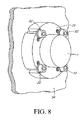
図8は、軸封止組立体25を容器壁部34に装着させた本発明の他の実施形態を示す。軸封止組立体25は、取付ボルト33等の固着手段を通じて容器壁部34に装着し、軸1が角度の心ずれを受ける場合の改善された封止を確保することができる。軸封止組立体25の外面を貫く取付ボルト33及びスロット(番号を付さず)は特許請求の範囲に記載のように軸封止組立体25を取り付ける1つの手段である。
FIG. 8 shows another embodiment of the present invention in which the
本発明の好ましい実施の形態を説明したが、本発明の他の特徴は、図示した本発明の実施形態の数多くの改変や変更、それらはすべて本発明の精神及び範囲を逸脱することなく達成できるものであるが、と同様、当業者には疑いようもなく明らかとなろう。 Although preferred embodiments of the present invention have been described, other features of the present invention can be achieved without departing from the spirit and scope of the present invention as illustrated by numerous modifications and alterations of the illustrated embodiments of the present invention. However, as will be obvious to those skilled in the art.
1・・・・・・軸
2・・・・・・固定ステータ
2a・・・・・固定ステータ(部品線)
3 ・・・・・ラビリンス封止装置
3a・・・・・アール付の面
4・・・・・・浮動ステータ
5・・・・・・流体もどし路
6・・・・・・軸と封止装置との隙間
7・・・・・・第1のOリング
8・・・・・・回転防止ピン
9・・・・・・ベント
10・・・・・回転防止溝(浮動ステータ)
11・・・・・球状界面
12・・・・・回転防止ピン
13・・・・・第2のOリング
14・・・・・ラビリンス封止パターン溝
15・・・・・第1のOリングチャネル
16・・・・・回転防止装置用キャビティ(固定ステータ)
17・・・・・ラビリンス封止装置の軸方向の面
18・・・・・浮動ステータの軸方向の面
19・・・・・第2のOリングチャネル
20・・・・・浮動ステータ/固定ステータ間の第1の隙間
21・・・・・浮動ステータ/固定ステータ間の第2の隙間
22・・・・・絞り溝
23・・・・・ラビリンスパターン環状溝
24・・・・・スリーブ
25・・・・・軸封止組立体
26・・・・・絞り(心合せスケート)
27・・・・・浮動ステータの環状溝
28・・・・・ラビリンス封止装置の通路
29・・・・・浮動ステータの通路
30・・・・・ハウジング
31・・・・・心ずれ角度
32・・・・・軸受及び軸受キャビティ
33・・・・・取付ボルト
34・・・・・容器壁部
1 ···
3... Labyrinth sealing device 3 a... Rounded surface 4... Floating
DESCRIPTION OF SYMBOLS 11 ... Spherical interface 12 ...
17 ...
27... Floating stator annular groove 28... Labyrinth sealing
Claims (26)
a.ハウジング(30)内に固定され、かつその半径方向内面に沿って環状チャネルを形成された固定ステータ(2)と、
b.前記固定ステータ(2)の前記環状チャネルに適合する軸封止装置(3)であって、第1及び第2の反対表面を有する軸封止装置(3、4)にして、前記軸封止装置(3)は、
(i) 浮動ステータ(4)であって、該浮動ステータ(4)の半径方向外面は、前記固定ステータ(2)の環状チャネルから半径方向に所定寸法だけ離れ、前記固定ステータ(2)の半径方向内面は実質的に凹形状をしている前記浮動ステータ(4)と、
(ii) ラビリンス封止装置(3)であって、該ラビリンス封止装置(3)は実質的に凸形状の半径方向外面を有し、該凸形状は該浮動ステータ(4)の半径方向内面に対応して球状界面を形成し、該ラビリンス封止装置(3)は、複数のラビリンスパターンの環状チャネルを有する半径方向内面を有し、且つ該ラビリンス封止装置(3)の半径方向内面は、軸(1)に対して隣接するが接触することなく、該軸(1)は前記ラビリンス封止装置(3)に対して自由に回転可能である前記ラビリンス封止装置(3)とを備える、軸封止組立体。 A shaft seal assembly (25) comprising:
a. A fixed stator (2) fixed in the housing (30) and formed with an annular channel along its radially inner surface;
b. A shaft sealing device (3) adapted to the annular channel of the fixed stator (2), the shaft sealing device (3, 4) having first and second opposite surfaces, wherein the shaft sealing Device (3)
(I) A floating stator (4), wherein a radial outer surface of the floating stator (4) is radially separated from an annular channel of the fixed stator (2) by a predetermined dimension, and the radius of the fixed stator (2) The floating stator (4) having a substantially concave inner surface,
(Ii) a labyrinth sealing device (3), the labyrinth sealing device (3) having a substantially convex radially outer surface, the convex shape being a radially inner surface of the floating stator (4) The labyrinth sealing device (3) has a radially inner surface with a plurality of labyrinth pattern annular channels, and the labyrinth sealing device (3) has a radially inner surface The labyrinth sealing device (3), which is adjacent to the shaft (1) but without contact, is freely rotatable with respect to the labyrinth sealing device (3). , Shaft sealing assembly.
一つのOリング(7、13)が、前記第1及び第2のOリングチャネル(15、19)内に配置された、軸封止組立体。 4. A shaft seal assembly according to claim 3, wherein the first and second O-ring channels are provided through the first and second radially oriented interfaces in the fixed stator (2). (15, 19)
A shaft seal assembly in which an O-ring (7, 13) is disposed in the first and second O-ring channels (15, 19).
前記ラビリンス封止装置(3)内に設けられた第1の流体戻し通路と、
前記浮動ステータ(4)内に設けられた第2の流体戻し通路と、
前記固定ステータ(2)内に設けられた第3の流体戻し通路とを更に備え、
前記第1、第2及び第3の流体戻し通路は互いに流体的連通している、軸封止組立体。 A shaft seal assembly (25) according to claim 1,
A first fluid return passage provided in the labyrinth sealing device (3);
A second fluid return passage provided in the floating stator (4);
A third fluid return passage provided in the fixed stator (2),
The shaft seal assembly, wherein the first, second and third fluid return passages are in fluid communication with each other.
a.前記ラビリンスシール装置(3)の半径方向内面内に設けられた一つの環状封止流体溝と、
b.前記固定ステータ(2)の半径方向外面内に設けられたに封止流体入口と、
c.前記浮動ステータ(4)内に設けられた第1の通路であって、該第1の通路は前記封止流体入口と流体的連通している前記第1の通路と、
d.前記ラビリンスシール装置(3)内に設けられた第1の通路であって、前記ラビリンスシール装置(3)内の該第1の通路は、前記浮動ステータ(4)内の前記第1の通路及び前記環状封止流体溝と流体的連通している前記第1の通路と、
e.前記固定ステータ(2)の前記半径方向外面内に設けられたに封止流体出口と、
f.前記浮動ステータ(4)内に設けられた第2の通路であって、該第2の通路は前記封止流体出口と流体的連通している前記第2の通路と、
g.前記ラビリンスシール装置(3)内に設けられた第2の通路であって、前記ラビリンスシール装置(3)内の該第2の通路は、前記浮動ステータ(4)内の前記第2の通路及び前記環状封止流体溝と流体的連通している前記第2の通路とを、
備える、軸封止組立体。 A shaft seal assembly (25) according to claim 1, comprising:
a. One annular sealing fluid groove provided in the radially inner surface of the labyrinth sealing device (3);
b. A sealing fluid inlet provided in a radially outer surface of the fixed stator (2);
c. A first passage provided in the floating stator (4), wherein the first passage is in fluid communication with the sealing fluid inlet;
d. A first passage provided in the labyrinth seal device (3), wherein the first passage in the labyrinth seal device (3) includes the first passage in the floating stator (4) and The first passage in fluid communication with the annular sealing fluid groove;
e. A sealing fluid outlet provided in the radially outer surface of the stationary stator (2);
f. A second passage provided in the floating stator (4), wherein the second passage is in fluid communication with the sealing fluid outlet;
g. A second passage provided in the labyrinth seal device (3), wherein the second passage in the labyrinth seal device (3) includes the second passage in the floating stator (4) and The second passage in fluid communication with the annular sealing fluid groove;
A shaft sealing assembly.
a. 軸封止組立体の固定ステータ(2)をハウジング(30)へ固定するステップであって、前記軸(1)はハウジング(30)に前記軸受けを介して枢動可能に取付けられ、軸封止組立体は前記軸受けに隣接して且つ軸受けの構外側に配置され、前記固定ステータ(2)は環状チャネルをその半径方向内面に沿って形成された、前記固定ステータ(2)を固定するステップと、
b. 前記軸封止組立体の軸封止部材を前記固定ステータ(2)の前記環状チャネル内に配置するステップであって、前記軸封止部材は前記環状チャネル内で前記固定ステータ(2)に対して半径方向に移動可能である、前記軸封止部材を配置するステップと、
c. 前記軸封止部材を、浮動ステータ(4)及びラビリンス封止装置(3)を有する形態にするステップであって、前記浮動ステータ(4)は凹状の半径方向内面を形成され、且つ前記ラビリンス封止装置(3)は凸状の半径方向外面を形成され、該凹状の半径方向内面及び凸状の半径方向外面が互いに界面を形成する前記形態ステップと、
d. 前記ラビリンス封止装置(3)を使用して、汚染物が前記軸受けに近づくのを防止し、且つ潤滑剤が、前記ラビリンス封止装置(3)と前記軸(1)との間の界面を介して前記軸受け上に存在するのを防止し、前記軸(1)は前記浮動ステータ(4)及び前記ラビリンス封止装置(3)に対して自由に回転する前記防止ステップと、
e. 前記軸(1)が、前記固定ステータ(2)及び前記軸封止部材の相対位置を介して半径方向へ移動するのを許容するステップと、
f. 前記軸(1)が、前記浮動ステータ(4)及び前記ラビリンス封止装置(3)の間の前記界面を介して角度的に移動するのを許容するステップと、
g. 前記軸(1)が、前記ラビリンス封止装置(3)及び前記軸(1)の間の前記界面を介して軸方向に移動するのを許容するステップとを備える、
前記軸受けを隔離する方法。 In a method of isolating a bearing during a shaft misalignment period, the method comprises:
a. Fixing the fixed stator (2) of the shaft seal assembly to the housing (30), wherein the shaft (1) is pivotally attached to the housing (30) via the bearing, Fixing the fixed stator (2), wherein the assembly is arranged adjacent to the bearing and outside the bearing, and the fixed stator (2) is formed with an annular channel along its radially inner surface; ,
b. Disposing a shaft sealing member of the shaft sealing assembly in the annular channel of the stationary stator (2), wherein the shaft sealing member is located in the annular channel with respect to the stationary stator (2); Disposing the shaft sealing member movable in a radial direction
c. Forming the shaft sealing member into a form having a floating stator (4) and a labyrinth sealing device (3), wherein the floating stator (4) has a concave radial inner surface and the labyrinth seal; The form step wherein the stop device (3) is formed with a convex radial outer surface, the concave radial inner surface and the convex radial outer surface forming an interface with each other;
d. The labyrinth sealing device (3) is used to prevent contaminants from approaching the bearing, and the lubricant creates an interface between the labyrinth sealing device (3) and the shaft (1). The shaft (1) is free to rotate with respect to the floating stator (4) and the labyrinth sealing device (3);
e. Allowing the shaft (1) to move radially via a relative position of the fixed stator (2) and the shaft sealing member;
f. Allowing the shaft (1) to move angularly through the interface between the floating stator (4) and the labyrinth sealing device (3);
g. Allowing the shaft (1) to move axially through the interface between the labyrinth sealing device (3) and the shaft (1),
A method of isolating the bearing.
a. 前記軸封止組立体の内部に加圧流体を導入するステップと、
b. 前記軸封止組立体の外部から加圧流体を集めるステップとを備える、
前記軸受けを隔離する方法。 The method of claim 25, further comprising:
a. Introducing a pressurized fluid into the shaft seal assembly;
b. Collecting pressurized fluid from the exterior of the shaft seal assembly.
A method of isolating the bearing.
Applications Claiming Priority (5)
| Application Number | Priority Date | Filing Date | Title |
|---|---|---|---|
| US69743405P | 2005-07-09 | 2005-07-09 | |
| US60/697,434 | 2005-07-09 | ||
| US11/405,207 US7396017B2 (en) | 2002-06-21 | 2006-04-17 | Shaft seal assembly |
| US11/405,207 | 2006-04-17 | ||
| PCT/US2006/014805 WO2007008270A1 (en) | 2005-07-09 | 2006-04-20 | Shaft seal assembly |
Publications (3)
| Publication Number | Publication Date |
|---|---|
| JP2009500578A JP2009500578A (en) | 2009-01-08 |
| JP2009500578A5 JP2009500578A5 (en) | 2009-06-18 |
| JP5228154B2 true JP5228154B2 (en) | 2013-07-03 |
Family
ID=37637455
Family Applications (1)
| Application Number | Title | Priority Date | Filing Date |
|---|---|---|---|
| JP2008520236A Expired - Fee Related JP5228154B2 (en) | 2005-07-09 | 2006-04-20 | Shaft sealing assembly and method for isolating bearings |
Country Status (12)
| Country | Link |
|---|---|
| US (4) | US7396017B2 (en) |
| EP (1) | EP1904771B9 (en) |
| JP (1) | JP5228154B2 (en) |
| AU (1) | AU2006269712B2 (en) |
| BR (1) | BRPI0612716A2 (en) |
| CA (1) | CA2614548C (en) |
| DK (1) | DK1904771T3 (en) |
| ES (1) | ES2402273T3 (en) |
| MX (1) | MX2007010692A (en) |
| PL (1) | PL1904771T3 (en) |
| PT (1) | PT1904771E (en) |
| WO (1) | WO2007008270A1 (en) |
Families Citing this family (54)
| Publication number | Priority date | Publication date | Assignee | Title |
|---|---|---|---|---|
| US8979093B2 (en) | 2002-06-21 | 2015-03-17 | Inpro/Seal, LLC | Pressure balanced shaft seal assembly |
| US7726661B2 (en) * | 2002-06-21 | 2010-06-01 | Inpro/Seal Llc | Pressure balanced shaft seal assembly |
| US9004491B2 (en) | 2002-06-21 | 2015-04-14 | Inpro/Seal Llc | Shaft seal assembly |
| US20160245410A1 (en) * | 2002-06-21 | 2016-08-25 | Inpro/Seal Llc | Shaft seal assembly |
| US8172232B2 (en) * | 2003-05-01 | 2012-05-08 | Advanced Technologies Group, Inc. | Non-contact seal for a gas turbine engine |
| US20050146096A1 (en) * | 2004-01-02 | 2005-07-07 | Swisher James A. | Trunnion assembly |
| US8604653B2 (en) | 2005-06-25 | 2013-12-10 | Inpro/Seal, LLC | Current diverter ring |
| US20110204734A1 (en) | 2005-06-25 | 2011-08-25 | Orlowski David C | Motor Grounding Seal |
| US20070040335A1 (en) * | 2005-08-22 | 2007-02-22 | General Electric Company | Axially adjustable sealing ring |
| US7828482B2 (en) * | 2006-08-28 | 2010-11-09 | Roller Bearing Company Of America, Inc. | Tungsten carbide enhanced bearing |
| US20080063330A1 (en) * | 2006-09-07 | 2008-03-13 | Orlowski David C | Bearing monitoring method |
| KR100947667B1 (en) | 2007-11-09 | 2010-03-12 | 장대웅 | Impeller Shaft supporting Structure Of Vertical Waltman Type Flowmeter |
| US8083235B2 (en) | 2008-02-28 | 2011-12-27 | A.W. Chesterton Company | Dynamic sealing |
| US20100201072A1 (en) * | 2009-02-06 | 2010-08-12 | Wians Jeffrey A | One piece shaft seal apparatus and method |
| PL2409055T3 (en) | 2009-03-16 | 2016-12-30 | Adjustable mechanical seal | |
| JP5593518B2 (en) * | 2009-03-17 | 2014-09-24 | エックステック インコーポレイティッド | Rolling equipment with oil recirculation system with pneumatic characteristics |
| GB201000062D0 (en) * | 2010-01-05 | 2010-02-17 | Cooper Roller Bearings Company | Bearing |
| US20110254231A1 (en) * | 2010-04-19 | 2011-10-20 | Isenberg Timothy J | Clean-In-Place Seal Assembly |
| KR101377540B1 (en) * | 2010-05-31 | 2014-03-26 | 주식회사 엘지화학 | Annealing apparatus and method for float glass ribbon |
| US20110138963A1 (en) * | 2010-06-29 | 2011-06-16 | Pischel Klaus | Active sealing-draining device |
| US8393796B2 (en) * | 2010-07-29 | 2013-03-12 | Ontario Drive & Gear Limited | Heavy duty bearing support system for ATV |
| US8727630B2 (en) * | 2010-12-23 | 2014-05-20 | Spyraflo, Inc. | Self-aligning miniature ball bearings with press-fit and self-clinching capabilities |
| US8932001B2 (en) * | 2011-09-06 | 2015-01-13 | General Electric Company | Systems, methods, and apparatus for a labyrinth seal |
| TW201338356A (en) | 2011-12-08 | 2013-09-16 | Inpro Seal Llc | Current diverter ring |
| WO2013103732A2 (en) | 2012-01-03 | 2013-07-11 | New Way Machine Components, Inc. | Air bearing for use as seal |
| US10598222B2 (en) | 2012-01-03 | 2020-03-24 | New Way Machine Components, Inc. | Air bearing for use as seal |
| WO2013126229A2 (en) | 2012-02-10 | 2013-08-29 | Orion Engineered Seals, Llc | Labyrinth seal |
| WO2014007971A1 (en) * | 2012-06-14 | 2014-01-09 | Inpro/Seal Llc | Shaft seal assembly |
| US9831739B2 (en) | 2012-06-18 | 2017-11-28 | Inpro/Seal Llc | Explosion-proof current diverting device |
| TWI600257B (en) | 2012-06-18 | 2017-09-21 | 英普羅密封有限責任公司 | Current diverter ring |
| WO2014042085A1 (en) * | 2012-09-11 | 2014-03-20 | イーグル工業株式会社 | Mechanical seal |
| AU2013348004B2 (en) | 2012-11-20 | 2017-12-21 | New Way Machine Components, Inc. | Air bearing for use as seal |
| WO2014100515A1 (en) * | 2012-12-19 | 2014-06-26 | Inpro/Seal Llc | Shaft seal assembly |
| US9188162B2 (en) | 2013-10-08 | 2015-11-17 | Kice Industries, Inc. | Bearing assembly with spacer for locating a seal sleeve |
| US9574610B2 (en) | 2013-10-08 | 2017-02-21 | Kice Industries, Inc. | Bearing assembly with outboard bearing support cartridge |
| WO2015054482A1 (en) | 2013-10-10 | 2015-04-16 | Weir Slurry Group, Inc. | Shaft seal assembly with contaminant detection system |
| US9709172B2 (en) | 2013-12-02 | 2017-07-18 | Farrel Corporation | Rotor shaft seal assembly |
| EP3183415B1 (en) * | 2014-08-18 | 2019-09-25 | Weatherford Technology Holdings, LLC | Pivot joint |
| US10100932B2 (en) * | 2014-09-29 | 2018-10-16 | New Way Machine Components, Inc. | Thrust bearing as a seal |
| EP3002487B1 (en) * | 2014-10-03 | 2018-12-12 | General Electric Technology GmbH | Sealing system |
| US10927961B2 (en) | 2015-04-21 | 2021-02-23 | Inpro/Seal Llc | Shaft seal assembly |
| CN107735605A (en) | 2015-04-21 | 2018-02-23 | 益保密封有限公司 | Shaft seal assembly |
| WO2016205789A1 (en) | 2015-06-18 | 2016-12-22 | Inpro/Seal Llc | Shaft seal assembly |
| US10236746B2 (en) * | 2015-12-15 | 2019-03-19 | Regal Beloit America, Inc. | Electric machine, lock and associated method |
| WO2017180658A1 (en) * | 2016-04-11 | 2017-10-19 | Prippell Technologies, Llc | Dynamic fluid seal |
| US10473222B2 (en) | 2016-04-11 | 2019-11-12 | Prippell Technologies, Llc | Dynamic fluid seal |
| CA2989756A1 (en) * | 2016-12-22 | 2018-06-22 | Harnischfeger Technologies, Inc. | Equalizer with lubrication |
| DE102018000935B4 (en) * | 2017-11-28 | 2022-12-22 | Carl Freudenberg Kg | sealing arrangement |
| CN108443503A (en) * | 2018-04-09 | 2018-08-24 | 中国船舶重工集团公司第七0三研究所 | A kind of small angle of cut gear train assembly sound combined sealing structure |
| DE102018205979A1 (en) * | 2018-04-19 | 2019-10-24 | Eagleburgmann Germany Gmbh & Co. Kg | FLOATING RING SEAL |
| TWI735960B (en) * | 2018-09-28 | 2021-08-11 | 美商英普羅密封有限責任公司 | Shaft seal assembly |
| US11608894B1 (en) | 2018-11-14 | 2023-03-21 | S. E. Yandle, II | Rescue mechanical seal and method |
| CN109854618A (en) * | 2019-03-26 | 2019-06-07 | 洛阳新强联回转支承股份有限公司 | A kind of low friction spherical joint bearing of super-large diameter |
| USD980069S1 (en) | 2020-07-14 | 2023-03-07 | Ball Corporation | Metallic dispensing lid |
Family Cites Families (24)
| Publication number | Priority date | Publication date | Assignee | Title |
|---|---|---|---|---|
| DE1054795B (en) * | 1956-07-10 | 1959-04-09 | Zoellner & Co | Labyrinth seal for water brakes and other gyroscopic machines that are only occasionally filled with water |
| US3240502A (en) * | 1962-09-14 | 1966-03-15 | Boeing Co | Self-aligning cable seal |
| US3243212A (en) * | 1962-11-16 | 1966-03-29 | Schaeffler Ohg Industriewerk | Ball and socket joint having an outer ring cracked radially |
| FR1535570A (en) * | 1967-06-20 | 1968-08-09 | Advanced self-centering bearing and method for its manufacture | |
| JPS6118281Y2 (en) * | 1979-09-03 | 1986-06-03 | ||
| US4305592A (en) * | 1979-10-23 | 1981-12-15 | Transamerica Delaval, Inc. | Gas seal bushing |
| JPS5674958U (en) * | 1979-11-14 | 1981-06-19 | ||
| JPS56106232U (en) * | 1980-01-18 | 1981-08-18 | ||
| JPS576162A (en) * | 1980-06-13 | 1982-01-13 | Mitsubishi Electric Corp | Noncontact seal ring shaft sealling device |
| US4402514A (en) * | 1981-09-10 | 1983-09-06 | General Electric Company | Fluid-cooled oil deflector |
| JPH0446149Y2 (en) * | 1986-03-06 | 1992-10-29 | ||
| DE3608782A1 (en) * | 1986-03-15 | 1987-09-24 | Thyssen Industrie | SWIVEL JOINT WITH FLOW CHANNELS |
| SE502274E (en) * | 1994-01-24 | 1999-04-21 | Kvaerner Pulping Tech | Diffuser and packing box intended to receive a rod for raising and lowering a strainer pack of such a diffuser |
| US5799950A (en) * | 1996-09-26 | 1998-09-01 | Caterpillar Inc. | Lubricated joint with equalizing pressure zone |
| US6004037A (en) * | 1998-06-04 | 1999-12-21 | Rexnord Corporation | Bearing assembly with spherical bearing surfaces |
| US6145843A (en) * | 1998-10-19 | 2000-11-14 | Stein Seal Company | Hydrodynamic lift seal for use with compressible fluids |
| US6168163B1 (en) * | 1998-11-18 | 2001-01-02 | Mixer Systems, Inc. | Shaft seal for mixers |
| AUPP908899A0 (en) * | 1999-03-10 | 1999-04-01 | Cherny Holdings Limited | Self-aligning shaft support |
| JP2000329097A (en) * | 1999-05-18 | 2000-11-28 | Mitsubishi Heavy Ind Ltd | Shaft seal device for turbo type compressor |
| US6648336B1 (en) * | 2000-08-01 | 2003-11-18 | Reliance Electric Technologies, Llc | Multi-function seal assembly for rotating shafts |
| JP2002228010A (en) * | 2000-10-25 | 2002-08-14 | Teijin Seiki Co Ltd | Vacuum sealing mechanism and vacuum sealing apparatus |
| US6592127B1 (en) * | 2002-01-23 | 2003-07-15 | Phlaver Inc. | Air purged shaft seal assembly |
| US7090403B2 (en) * | 2002-06-21 | 2006-08-15 | Isotech Of Illinois, Inc. | Articulated seal |
| JP4090392B2 (en) * | 2003-06-23 | 2008-05-28 | ホソカワミクロン株式会社 | Shaft seal structure and stirring device using the same |
-
2006
- 2006-04-17 US US11/405,207 patent/US7396017B2/en not_active Expired - Lifetime
- 2006-04-20 MX MX2007010692A patent/MX2007010692A/en active IP Right Grant
- 2006-04-20 PL PL06758424T patent/PL1904771T3/en unknown
- 2006-04-20 WO PCT/US2006/014805 patent/WO2007008270A1/en active Application Filing
- 2006-04-20 AU AU2006269712A patent/AU2006269712B2/en active Active
- 2006-04-20 JP JP2008520236A patent/JP5228154B2/en not_active Expired - Fee Related
- 2006-04-20 ES ES06758424T patent/ES2402273T3/en active Active
- 2006-04-20 BR BRPI0612716-9A patent/BRPI0612716A2/en active Search and Examination
- 2006-04-20 CA CA2614548A patent/CA2614548C/en active Active
- 2006-04-20 PT PT67584243T patent/PT1904771E/en unknown
- 2006-04-20 EP EP06758424.3A patent/EP1904771B9/en active Active
- 2006-04-20 DK DK06758424.3T patent/DK1904771T3/en active
-
2008
- 2008-05-30 US US12/156,476 patent/US7631878B1/en active Active
-
2009
- 2009-11-04 US US12/612,244 patent/US20100109251A1/en not_active Abandoned
-
2011
- 2011-04-11 US US13/084,309 patent/US20110187055A1/en not_active Abandoned
Also Published As
| Publication number | Publication date |
|---|---|
| US7631878B1 (en) | 2009-12-15 |
| JP2009500578A (en) | 2009-01-08 |
| ES2402273T3 (en) | 2013-04-30 |
| AU2006269712B2 (en) | 2012-04-19 |
| DK1904771T3 (en) | 2013-04-08 |
| CA2614548A1 (en) | 2007-01-18 |
| US7396017B2 (en) | 2008-07-08 |
| US20110187055A1 (en) | 2011-08-04 |
| US20100109251A1 (en) | 2010-05-06 |
| EP1904771B1 (en) | 2012-12-26 |
| CA2614548C (en) | 2014-11-25 |
| PT1904771E (en) | 2013-04-01 |
| EP1904771A1 (en) | 2008-04-02 |
| EP1904771B9 (en) | 2013-05-15 |
| BRPI0612716A2 (en) | 2010-11-30 |
| WO2007008270A1 (en) | 2007-01-18 |
| EP1904771A4 (en) | 2009-11-11 |
| AU2006269712A1 (en) | 2007-01-18 |
| PL1904771T3 (en) | 2013-06-28 |
| US20070241514A1 (en) | 2007-10-18 |
| MX2007010692A (en) | 2007-11-08 |
Similar Documents
| Publication | Publication Date | Title |
|---|---|---|
| JP5228154B2 (en) | Shaft sealing assembly and method for isolating bearings | |
| CA2695267C (en) | Pressure balanced shaft seal assembly | |
| US8979093B2 (en) | Pressure balanced shaft seal assembly | |
| US9004491B2 (en) | Shaft seal assembly | |
| TW201530025A (en) | Shaft seal assembly | |
| US20150345643A1 (en) | Shaft Seal Assembly | |
| US20140232071A1 (en) | Shaft Seal Assembly | |
| US7055826B2 (en) | Seal and bearing assembly | |
| JP4442461B2 (en) | Liquid lubricated foil type hydrodynamic bearing | |
| WO2014007971A1 (en) | Shaft seal assembly | |
| AU2002329686A1 (en) | Seal and bearing assembly | |
| CA2876871A1 (en) | Shaft seal assembly |
Legal Events
| Date | Code | Title | Description |
|---|---|---|---|
| A521 | Request for written amendment filed |
Free format text: JAPANESE INTERMEDIATE CODE: A523 Effective date: 20090420 |
|
| A621 | Written request for application examination |
Free format text: JAPANESE INTERMEDIATE CODE: A621 Effective date: 20090420 |
|
| A977 | Report on retrieval |
Free format text: JAPANESE INTERMEDIATE CODE: A971007 Effective date: 20111007 |
|
| A131 | Notification of reasons for refusal |
Free format text: JAPANESE INTERMEDIATE CODE: A131 Effective date: 20111013 |
|
| A601 | Written request for extension of time |
Free format text: JAPANESE INTERMEDIATE CODE: A601 Effective date: 20120112 |
|
| A602 | Written permission of extension of time |
Free format text: JAPANESE INTERMEDIATE CODE: A602 Effective date: 20120119 |
|
| A521 | Request for written amendment filed |
Free format text: JAPANESE INTERMEDIATE CODE: A523 Effective date: 20120216 |
|
| A131 | Notification of reasons for refusal |
Free format text: JAPANESE INTERMEDIATE CODE: A131 Effective date: 20120723 |
|
| A521 | Request for written amendment filed |
Free format text: JAPANESE INTERMEDIATE CODE: A523 Effective date: 20120726 |
|
| A01 | Written decision to grant a patent or to grant a registration (utility model) |
Free format text: JAPANESE INTERMEDIATE CODE: A01 Effective date: 20121126 |
|
| A711 | Notification of change in applicant |
Free format text: JAPANESE INTERMEDIATE CODE: A711 Effective date: 20121225 |
|
| A61 | First payment of annual fees (during grant procedure) |
Free format text: JAPANESE INTERMEDIATE CODE: A61 Effective date: 20121225 |
|
| A521 | Request for written amendment filed |
Free format text: JAPANESE INTERMEDIATE CODE: A821 Effective date: 20121225 |
|
| A521 | Request for written amendment filed |
Free format text: JAPANESE INTERMEDIATE CODE: A523 Effective date: 20130214 |
|
| FPAY | Renewal fee payment (event date is renewal date of database) |
Free format text: PAYMENT UNTIL: 20160329 Year of fee payment: 3 |
|
| R150 | Certificate of patent or registration of utility model |
Free format text: JAPANESE INTERMEDIATE CODE: R150 |
|
| LAPS | Cancellation because of no payment of annual fees |