JP5227954B2 - Chain tensioning device that connects two strands of chain drive - Google Patents
Chain tensioning device that connects two strands of chain drive Download PDFInfo
- Publication number
- JP5227954B2 JP5227954B2 JP2009509983A JP2009509983A JP5227954B2 JP 5227954 B2 JP5227954 B2 JP 5227954B2 JP 2009509983 A JP2009509983 A JP 2009509983A JP 2009509983 A JP2009509983 A JP 2009509983A JP 5227954 B2 JP5227954 B2 JP 5227954B2
- Authority
- JP
- Japan
- Prior art keywords
- chain
- tensioner
- guide element
- chain guide
- groove
- Prior art date
- Legal status (The legal status is an assumption and is not a legal conclusion. Google has not performed a legal analysis and makes no representation as to the accuracy of the status listed.)
- Expired - Fee Related
Links
- 238000002485 combustion reaction Methods 0.000 claims description 10
- 238000013016 damping Methods 0.000 claims description 6
- 230000005540 biological transmission Effects 0.000 description 16
- 239000000463 material Substances 0.000 description 7
- 230000033001 locomotion Effects 0.000 description 5
- 239000004677 Nylon Substances 0.000 description 2
- NIXOWILDQLNWCW-UHFFFAOYSA-N acrylic acid group Chemical group C(C=C)(=O)O NIXOWILDQLNWCW-UHFFFAOYSA-N 0.000 description 2
- 229910045601 alloy Inorganic materials 0.000 description 2
- 239000000956 alloy Substances 0.000 description 2
- 239000002131 composite material Substances 0.000 description 2
- 230000007246 mechanism Effects 0.000 description 2
- 229920001778 nylon Polymers 0.000 description 2
- 239000004033 plastic Substances 0.000 description 2
- 239000011347 resin Substances 0.000 description 2
- 229920005989 resin Polymers 0.000 description 2
- 230000007704 transition Effects 0.000 description 2
- 229910000639 Spring steel Inorganic materials 0.000 description 1
- 230000006835 compression Effects 0.000 description 1
- 238000007906 compression Methods 0.000 description 1
- 230000009977 dual effect Effects 0.000 description 1
- 230000000694 effects Effects 0.000 description 1
- 230000009191 jumping Effects 0.000 description 1
- 230000007774 longterm Effects 0.000 description 1
- 230000002265 prevention Effects 0.000 description 1
Images


Classifications
-
- F—MECHANICAL ENGINEERING; LIGHTING; HEATING; WEAPONS; BLASTING
- F16—ENGINEERING ELEMENTS AND UNITS; GENERAL MEASURES FOR PRODUCING AND MAINTAINING EFFECTIVE FUNCTIONING OF MACHINES OR INSTALLATIONS; THERMAL INSULATION IN GENERAL
- F16H—GEARING
- F16H7/00—Gearings for conveying rotary motion by endless flexible members
- F16H7/08—Means for varying tension of belts, ropes, or chains
-
- F—MECHANICAL ENGINEERING; LIGHTING; HEATING; WEAPONS; BLASTING
- F16—ENGINEERING ELEMENTS AND UNITS; GENERAL MEASURES FOR PRODUCING AND MAINTAINING EFFECTIVE FUNCTIONING OF MACHINES OR INSTALLATIONS; THERMAL INSULATION IN GENERAL
- F16H—GEARING
- F16H7/00—Gearings for conveying rotary motion by endless flexible members
- F16H7/18—Means for guiding or supporting belts, ropes, or chains
-
- F—MECHANICAL ENGINEERING; LIGHTING; HEATING; WEAPONS; BLASTING
- F16—ENGINEERING ELEMENTS AND UNITS; GENERAL MEASURES FOR PRODUCING AND MAINTAINING EFFECTIVE FUNCTIONING OF MACHINES OR INSTALLATIONS; THERMAL INSULATION IN GENERAL
- F16H—GEARING
- F16H7/00—Gearings for conveying rotary motion by endless flexible members
- F16H7/08—Means for varying tension of belts, ropes, or chains
- F16H2007/0802—Actuators for final output members
- F16H2007/0804—Leaf springs
-
- F—MECHANICAL ENGINEERING; LIGHTING; HEATING; WEAPONS; BLASTING
- F16—ENGINEERING ELEMENTS AND UNITS; GENERAL MEASURES FOR PRODUCING AND MAINTAINING EFFECTIVE FUNCTIONING OF MACHINES OR INSTALLATIONS; THERMAL INSULATION IN GENERAL
- F16H—GEARING
- F16H7/00—Gearings for conveying rotary motion by endless flexible members
- F16H7/08—Means for varying tension of belts, ropes, or chains
- F16H2007/0863—Finally actuated members, e.g. constructional details thereof
- F16H2007/0874—Two or more finally actuated members
-
- F—MECHANICAL ENGINEERING; LIGHTING; HEATING; WEAPONS; BLASTING
- F16—ENGINEERING ELEMENTS AND UNITS; GENERAL MEASURES FOR PRODUCING AND MAINTAINING EFFECTIVE FUNCTIONING OF MACHINES OR INSTALLATIONS; THERMAL INSULATION IN GENERAL
- F16H—GEARING
- F16H7/00—Gearings for conveying rotary motion by endless flexible members
- F16H7/08—Means for varying tension of belts, ropes, or chains
- F16H7/0829—Means for varying tension of belts, ropes, or chains with vibration damping means
- F16H7/0831—Means for varying tension of belts, ropes, or chains with vibration damping means of the dry friction type
Description
関連出願の参照
これは、本出願が優先権を主張する、2003年10月15日に出願され、2005年4月21日に米国特許出願公開第2005/0085322A1号明細書として発行された、同時係属原特許出願第10/685,849号明細書の一部継続出願である。上述した出願は、その開示内容が参照により本明細書に援用される。
REFERENCE TO RELATED APPLICATIONS This is a concurrent application filed on October 15, 2003 and issued as US Patent Application Publication No. 2005 / 0085322A1 on April 21, 2005, to which this application claims priority. This is a continuation-in-part application of pending original patent application No. 10 / 685,849. The above application is hereby incorporated by reference in its entirety.
本発明は、内燃機関で適用される閉ループチェーン駆動テンショナの分野に関する。より詳細には、本発明は、単一取付点を中心に枢動するデュアルテンショナに関する。 The present invention relates to the field of closed loop chain drive tensioners applied in internal combustion engines. More particularly, the present invention relates to a dual tensioner that pivots about a single attachment point.
チェーンが内燃機関の動作軸に連結される複数のスプロケット間を走行する際に、閉ループ動力伝達チェーンを制御するために、緊張装置が使用される。このシステムでは、チェーンは、動力を、駆動軸からカムシャフト等の従動軸に伝達し、それにより、常に、チェーンの一部が張られている一方で一部が緩んでいる可能性がある。歯付きチェーン駆動システムの場合のように、歯の雑音、すべりまたは噛合い不良を防止するために、チェーンにある程度の緊張を付与し維持することが重要である。かかるすべりの防止は、特に、内燃機関のチェーン駆動カムシャフトの場合に重要である。それは、歯の飛びによってカムシャフトのタイミングが狂うこととなり、エンジンに対する損傷がもたらされるかまたはエンジンが完全に機能しなくなるためである。 A tensioning device is used to control the closed loop power transmission chain as the chain travels between a plurality of sprockets connected to the operating shaft of the internal combustion engine. In this system, the chain transmits power from the drive shaft to a driven shaft, such as a camshaft, so that it is always possible that a portion of the chain is tensioned while a portion is loose. As in the case of a toothed chain drive system, it is important to apply and maintain some tension on the chain to prevent tooth noise, slippage or poor meshing. Such slippage prevention is particularly important in the case of a chain drive camshaft of an internal combustion engine. This is because tooth jumping can cause camshaft timing to be out of order, resulting in damage to the engine or failure of the engine.
しかしながら、内燃機関の過酷な環境では、多くの要因によって、チェーンのいずれの部分においても緊張が変動する。たとえば、過度な温度変動、およびエンジンのさまざまな部分の間の熱膨張係数の相違により、チェーン緊張が過度に高いレベルと非常に低いレベルとの間で変化する可能性がある。長期間の使用の間に、動力伝達システムの部品に対する摩損により、チェーン緊張が着実に低減する可能性がある。さらに、カムシャフトおよびクランクシャフトが引き起こす捩り振動により、チェーン緊張が著しく変動する。たとえば、エンジンの停止中かまたはエンジン始動時の失敗で発生するエンジンの逆回転によってもまた、チェーン緊張が著しく変動する可能性がある。これらの理由により、チェーンの張り側における過度な緊張力を除去すると同時に、チェーンの緩み側に適当な緊張が確実に加わるようにする機構が望まれる。 However, in the harsh environment of an internal combustion engine, the tension varies throughout the chain due to many factors. For example, excessive temperature fluctuations and differences in thermal expansion coefficients between various parts of the engine can cause chain tension to vary between excessively high and very low levels. During long-term use, chain tension can steadily decrease due to wear on the components of the power transmission system. In addition, torsional vibrations caused by camshafts and crankshafts cause significant fluctuations in chain tension. For example, chain tension can also fluctuate significantly due to reverse rotation of the engine that occurs when the engine is stopped or due to a failure at engine start. For these reasons, it is desirable to have a mechanism that removes excessive tension on the tight side of the chain while ensuring that proper tension is applied to the loose side of the chain.
液圧テンショナは、適当なチェーン緊張を維持する一般的な方法である。一般に、これら機構は、チェーンの動力伝達システムの緩み側を押すレバーアームを採用する。液圧によってピストンがレバーアームに対して付勢され、それにより、レバーアームが強制的にチェーンに係合し、緩み状態の間にその張りを強化する。 Hydraulic tensioners are a common way to maintain proper chain tension. Generally, these mechanisms employ lever arms that push the loose side of the chain's power transmission system. The hydraulic pressure biases the piston against the lever arm, thereby forcing the lever arm to engage the chain and strengthens its tension during the loose state.
1つまたは複数のばねに過度に応力をかけるほど荷重変動が厳しくないチェーンまたはベルトを制御するためには、一般に、ブレードテンショナが使用される。従来のブレードスプリングテンショナは、湾曲したチェーン摺動面を有するブレードシューを含み、そのチェーン摺動面は、それが係合されるチェーンのストランドとの接触を維持する。チェーンに加えられる緊張力の量を増大させるために、ブレードシューとチェーン摺動面との間に少なくとも1つのブレードスプリングが取り付けられる。ブラケットがブレードシューおよびチェーン摺動面を収容する。ブラケットは、ボルト、リベットまたは他のかかる手段によりエンジンに固定取付される。変化する緊張荷重に応じてブラケットが枢動することができるようにする取付手段は1つしかない可能性がある。枢支点は、要求に応じてブラケットの端部にあっても中央にあってもよい。あるいは、ブラケットを、テンショナのいかなる枢動動作をも有効に妨げる2つ以上の取付手段によりエンジンに固定取付してもよい。いずれの場合も、取付手段は、テンショナが係合されるチェーンのストランドに隣接して位置する。取付手段は、チェーンループ自体の外側に位置することが多い。 Blade tensioners are typically used to control chains or belts that are not subject to load fluctuations that are excessively stressed on one or more springs. A conventional blade spring tensioner includes a blade shoe having a curved chain sliding surface that maintains contact with the strand of the chain with which it is engaged. In order to increase the amount of tension applied to the chain, at least one blade spring is mounted between the blade shoe and the chain sliding surface. A bracket houses the blade shoe and the chain sliding surface. The bracket is fixedly attached to the engine by bolts, rivets or other such means. There may be only one attachment means that allows the bracket to pivot in response to changing tension loads. The pivot point may be at the end of the bracket or at the center as required. Alternatively, the bracket may be fixedly attached to the engine by two or more attachment means that effectively prevent any pivoting movement of the tensioner. In either case, the attachment means is located adjacent to the strand of the chain with which the tensioner is engaged. The attachment means is often located outside the chain loop itself.
図1は、ブレードテンショナおよびガイドを有する従来技術によるチェーン駆動システムを示す。閉ループチェーン8が、駆動スプロケット12と従動スプロケット10とを取り囲んでいる。各スプロケット10および12は、前進運動を維持しながら独立して加速し減速する。チェーンの張りストランドにおいてブラケット7に固定ガイド14が取り付けられている。チェーンの緩みストランドにおいて、テンショナ16がガイド14に対向しており、テンショナ16は、ブラケット7に少なくとも幾分堅く固定されており、チェーンの張りストランドに向かって付勢されている。ボルト18が、テンショナ16およびガイド14を含むブラケットをエンジンブロック(図示せず)に締結している。
FIG. 1 shows a prior art chain drive system having a blade tensioner and a guide. A closed
駆動スプロケット12が加速するかまたは従動スプロケット10が減速するとき、チェーンの張りストランドにエネルギー波または高い局部荷重がもたらされ、それは、速度が変化したスプロケットから他方のスプロケットに向かって移動する。チェーン8は、開始スプロケットに接触しているチェーンのリンクから他方のスプロケットに接触しているチェーンのリンクまでの距離を、あり得る最短距離、すなわち直線でわたろうとする。エネルギーは、エネルギーを吸収するガイド14の端部に達するまで、チェーンの自由ストランドにおいてリンクを通して移動する。高い局部荷重を常に吸収する結果、ガイド14の端部は著しく摩耗する。エネルギー波もまた存在する可能性があり、緩みストランドに向けられた場合同様の結果をもたらす可能性がある。しかしながら、これらエネルギー波の影響は、テンショナがチェーンをいかに緩ませないかに応じて、まったく発生しない可能性もある。
As the drive sprocket 12 accelerates or the driven
米国特許第5,967,922号明細書は、第1スライドブロックおよび第2スライドブロックが、チェーンの緩み側の両側にあるように取り付けられているテンションレバーを含む緊張装置を開示している。第1スライドブロックは、チェーンの張り側においてガイドレールに枢動可能に取付されている。第2スライドブロックは、圧縮ばねおよびピストンを備えたテンション要素により、チェーンの緩み側の両側のうちの一方に対して付勢されている。 U.S. Pat. No. 5,967,922 discloses a tensioning device that includes a tension lever that is mounted such that the first slide block and the second slide block are on opposite sides of the chain. The first slide block is pivotally attached to the guide rail on the chain tension side. The second slide block is biased against one of the two sides on the slack side of the chain by a tension element including a compression spring and a piston.
米国特許第6,322,470号明細書は、同じチェーンの2つの別個のストランドに同時に張力をかけるように使用される一対の枢動アームを含むテンショナを開示している。2つのストランドの間に、固定ピンを備えたレバーが位置している。アームは、固定ピンに枢支取付されており、チェーンのストランドの外側に延在している。それらは、チェーンの外側部分と接触するシューを含む。レバーの回転により、固定ピンが横方向に移動しアームを引き寄せることにより、チェーンの別個のストランドに同時に緊張を加える。 U.S. Pat. No. 6,322,470 discloses a tensioner that includes a pair of pivot arms that are used to simultaneously tension two separate strands of the same chain. A lever with a fixing pin is located between the two strands. The arm is pivotally attached to the fixed pin and extends outside the strand of the chain. They include a shoe that contacts the outer part of the chain. The rotation of the lever causes the fixing pin to move laterally and pull the arms together, thereby simultaneously tensioning the separate strands of the chain.
特開2003−074652号公報は、2つのスプロケットを連結する中心線に支持部材が枢動可能に位置しているテンショナを開示している。チェーンの両側において支持部材に押圧部材が取り付けられている。チェーンの緩みストランドおよび張りストランドに与えられる減衰は、各ストランドに対して個別であり、それは、押圧部材の各々がチェーンに対して浮遊するためである。2つの押圧部材の間には1つの枢軸しかないが、一方に対する荷重が他方に影響しようとし、押圧部材がチェーンの上で前後に波打つ。 Japanese Patent Application Laid-Open No. 2003-074652 discloses a tensioner in which a support member is pivotally positioned at a center line connecting two sprockets. A pressing member is attached to the support member on both sides of the chain. The damping imparted to the slack and tension strands of the chain is individual for each strand because each of the pressing members floats against the chain. There is only one pivot between the two pressing members, but the load on one tries to affect the other, and the pressing member undulates back and forth on the chain.
図2を参照すると、米国特許出願公開第2005/0085322A1号明細書に開示されているようなチェーンテンショナ組立体が示されている。チェーンテンショナ組立体は、テンショナ116とチェーンガイド114とからなり、それらはともにブラケット136に固定されている。テンショナ116はチェーン108の一方のストランドに係合し、チェーンガイド114はチェーンの他方のストランドに係合している。ブラケットは、枢支手段120においてエンジンハウジングに枢支取付されており、枢支手段120は、チェーンの2つのストランドの間で、かつ駆動スプロケット112の中心軸と従動スプロケット110の中心軸との間に形成される中心線に沿った、穴128に位置する。ブラケットは、チェーンのいずれかのストランドにもたらされる緩みおよび張りの両緊張状態に応じて、枢支手段120を中心に右回り方向または左回り方向のいずれかに枢動することができる。
Referring to FIG. 2, a chain tensioner assembly as disclosed in US Patent Application Publication No. 2005 / 0085322A1 is shown. The chain tensioner assembly includes a
通常の閉ループチェーン駆動動力伝達システムでは、一方のストランドが、動作中の時間の大部分は張られており、他方のストランドが大部分の時間緩んでいることになる。従来技術によるテンショナは、単にガイド要素を張りストランドに隣接して配置する一方で、緊張装置を大部分は緩んでいるストランドに接触して配置することにより、この状態に対処する。これら装置は、優勢的な緊張状態から、張りストランドが緩み緩みストランドが張られる反対の緊張状態へ、平滑に遷移することができないことが多い。チェーンシステム全体を通して一貫して緊張が平衡するように、チェーンの優勢的な緊張状態において逆転状態に平滑に適合することができるテンショナがあることが望ましい。 In a typical closed loop chain drive power transmission system, one strand will be stretched for most of the time during operation and the other strand will be loose for most of the time. Prior art tensioners address this situation by simply placing the guide element adjacent to the tensioned strand while placing the tensioning device in contact with the strand that is largely loose. These devices often cannot smoothly transition from a prevailing tension state to an opposite tension state where the tension strands loosen and loose strands are tensioned. It is desirable to have a tensioner that can smoothly adapt to the reverse state in the dominant tension state of the chain so that the tension is consistently balanced throughout the chain system.
本発明は、内燃機関で使用される閉ループチェーン駆動システム用のテンショナである。それを、駆動軸と少なくとも1つのカムシャフトとの間の閉ループ動力伝達システムで、または駆動軸とバランスシャフトとの間のバランスシャフトシステムで利用してもよい。テンショナは、閉ループチェーンのストランドの間に位置するブラケットと、ブラケットと一体化した2つの緊張装置と、を含み、各緊張装置は、チェーンの2つのストランドのうちの一方の長さの一部に摺動可能に係合する細長いコンプライアントチェーンガイド要素を有する。ブラケットは、そのブラケットがストランドの一方または両方の緊張の変動に応じて取付点を中心に枢動するのを可能にするために、エンジンハウジングの単一点に取り付けられる。枢支点は、コンプライアントチェーンガイド要素の各々の長さに沿ったおよそ中間点から等距離であり、それにより、実質的に二等辺三角形を形成する。枢支点は、駆動スプロケットの軸と従動スプロケットの軸との間に存在する擬似中心線に沿って位置することが好ましい。 The present invention is a tensioner for a closed loop chain drive system used in an internal combustion engine. It may be utilized in a closed loop power transmission system between the drive shaft and at least one camshaft or in a balance shaft system between the drive shaft and the balance shaft. The tensioner includes a bracket positioned between the strands of the closed loop chain and two tensioning devices integral with the bracket, each tensioning device being part of the length of one of the two strands of the chain. It has an elongated compliant chain guide element that slidably engages. The bracket is attached to a single point on the engine housing to allow the bracket to pivot about the attachment point in response to variations in tension on one or both strands. The pivot points are equidistant from approximately the midpoint along the length of each of the compliant chain guide elements, thereby forming a substantially isosceles triangle. The pivot point is preferably located along a pseudo centerline that exists between the axis of the drive sprocket and the axis of the driven sprocket.
チェーンに対する追加の付勢力を、ブラケットとコンプライアントチェーンガイド要素との間に少なくとも1つのブレードスプリングを挿入することによって提供してもよい。エンジン作動中にチェーンの各ストランドの緊張が変動すると、ブラケットが枢支点を中心に枢動し、それにより、緊張装置の一方が、緩んできているチェーンのストランドに対する緊張を増大させることができ、同時に、張られてきている他方のストランドに過剰に張力をかけない。これにより、チェーンの緊張における迅速に変動する弛みモードと張りモードとの間の遷移が平滑になる。 Additional biasing force on the chain may be provided by inserting at least one blade spring between the bracket and the compliant chain guide element. As the tension of each strand of the chain fluctuates during engine operation, the bracket pivots about the pivot point so that one of the tensioning devices can increase the tension on the loose strand of the chain, At the same time, it does not over tension the other strand that is being stretched. This smoothes the transition between the rapidly changing slack and tension modes in chain tension.
図3は、本発明のテンショナの第1実施形態を示す。テンショナ210は、内燃機関の閉ループチェーン駆動システムに取り付けられている。第1実施形態に関連する図面によって例示するように、動力伝達システムを示す。動力伝達システムは、連続したチェーンによって少なくとも1つのカムシャフトに動作可能に連結された駆動軸からなる。しかしながら、本発明はまた、駆動軸が閉ループチェーンによってバランスシャフトに連結される閉ループバランスシャフトシステムにも適用可能である。 FIG. 3 shows a first embodiment of the tensioner of the present invention. The tensioner 210 is attached to the closed loop chain drive system of the internal combustion engine. A power transmission system is shown as illustrated by the drawings associated with the first embodiment. The power transmission system consists of a drive shaft operably connected to at least one camshaft by a continuous chain. However, the present invention is also applicable to a closed loop balance shaft system in which the drive shaft is connected to the balance shaft by a closed loop chain.
図3に示す動力伝達チェーン駆動システムは、チェーン200によって少なくとも1つの従動スプロケット204に動作可能に連結される、駆動軸(図示せず)に取り付けられている駆動スプロケット202によって具現化される。従動スプロケット204は、カムシャフト(図示せず)の一端に連結されている。内燃機関は、エンジン設計に応じて、1つ(添付図面に示すように)、2つまたは4つのカムシャフトを有する場合がある。以下、単一カムシャフトに関して、テンショナ210の第1実施形態について説明する。しかしながら、テンショナ210を、2つ以上のカムシャフトを有する動力伝達システムで使用してもよい、ということが理解されるべきである。
The power transmission chain drive system shown in FIG. 3 is embodied by a
テンショナ210は、外面214および内面215(ここで図4を参照)を有するブラケット212を含む。テンショナ210は、枢支取付具219をもたらす、たとえばボルト、リベットまたはピン等の取付手段により、エンジン(図示せず)のハウジングに枢支取付されている。枢支取付具219は、ブラケット212の底部に近接して配置されている枢支穴218に挿入されている。枢支取付具219は、チェーン緊張の小さい変動によってもたらされる可能性のある最小エネルギー入力を吸収するために十分なトルクで、ブラケット212をエンジンハウジングに固定する、捩り減衰手段を含む。捩り減衰を、枢支点においてブラケットに所定の荷重を加えることによって提供してもよい。たとえば、ブラケットとエンジンとの間に所望の量の摩擦力をもたらすように、枢支取付具(ファスナ)とブラケットとの間でばね座金を圧縮させてもよい。エンジンに対するブラケットのいかなる回転運動も、ブラケットとエンジンとの間の摩擦力によって抵抗される。この摩擦減衰力を、枢支点において加えられる力を変更することにより、ブラケットとエンジンとの間の接触配置を変更することにより(たとえば部品の構成または接触面積の量を変更することにより)、またはブラケットとエンジンとの間の所望の摩擦係数をもたらすブラケット材料を選択することにより等、多くの方法で調整することができる。
Tensioner 210 includes a
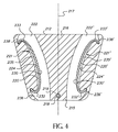
図4を参照すると、ブラケット212の内面215が示されている。内面215は、緊張装置221および221’を収容し、それらは各々、チェーン200の2つのストランド(図示せず)のうちの一方に動作可能に係合されている。緊張装置221および221’は、それぞれ、コンプライアントチェーンガイド要素220および220’を含む。図5を参照すると、コンプライアントチェーンガイド要素220(220’)は、細長いチェーン摺動面230(230’)からなり、それは実質的にその全長に沿ってチェーン200の単一ストランドとの連続した摺動面を維持する。
Referring to FIG. 4, the
枢支穴218が、それぞれのコンプライアントチェーンガイド要素220および220’の各々の細長いチェーン摺動面230および230’の長さに沿ったおよそ中間点から実質的に等距離に位置することにより、実質的に二等辺三角形を形成している。好ましい実施形態では、枢支穴218は、駆動スプロケット202の軸を従動スプロケット204の軸に連結する擬似垂直中心線217(図3および図4を参照されたい)に沿って位置している。2つ以上の従動スプロケットがある場合、従動スプロケットの各々の軸の間の等距離の点が、擬似垂直中心線217に垂直に交差する。
The
図5を参照すると、コンプライアントチェーンガイド要素220(220’)のチェーン摺動面230(230’)とは反対側に、内面235(235’)がある。チェーン摺動面230(230’)に垂直に、かつコンプライアントチェーンガイド要素220(220’)の両縁に沿って長手方向に、ガイドレール234(234’)が配置されており、それは、チェーンがチェーン摺動面230(230’)に配置され続けるようにする。コンプライアントチェーンガイド要素220(220’)は、近位端232(232’)と遠位端233(233’)とを有する。近位端232(232’)および遠位端233(233’)は、コンプライアントチェーンガイド要素の中間部分に向かって戻るように湾曲し、実質的にフック型端部を形成している。 Referring to FIG. 5, there is an inner surface 235 (235 ') on the opposite side of the compliant chain guide element 220 (220') from the chain sliding surface 230 (230 '). Guide rails 234 (234 ') are arranged perpendicular to the chain sliding surface 230 (230') and longitudinally along both edges of the compliant chain guide element 220 (220 '), which Continue to be disposed on the chain sliding surface 230 (230 ′). The compliant chain guide element 220 (220 ') has a proximal end 232 (232') and a distal end 233 (233 '). Proximal end 232 (232 ') and distal end 233 (233') are curved back toward the middle portion of the compliant chain guide element, forming a substantially hook-shaped end.
再び図4を参照すると、各コンプライアントチェーンガイド要素220および220’は、それぞれ溝222および222’内に取り付けられており、溝222および222’は、ブラケット212の内面215において構造リブ216と溝壁224および224’それぞれとの間に形成されている。構造リブ216は、図4に示すように、内面215において幅狭の長手方向構成を備えてもよく、またははるかに狭い面積を含んでもよい。リブ216の設計は、種々のチェーン駆動構成によってテンショナ210に加えられる可能性のある機械的応力によって確定される。各溝222および222’は、チェーン200の単一ストランド用のガイドとして作用する。
Referring again to FIG. 4, each compliant
コンプライアントチェーンガイド要素220の近位端232は、近位溝凹部236において突起の周囲に非永久的に係合され、遠位端233もまた、遠位溝凹部238の突起の周囲に非永久的に係合されている。コンプライアントチェーンガイド要素220の内面235は、溝壁224に面している。コンプライアントチェーンガイド要素220は、それが細長いばねのように作用するのを可能にする、半可撓性コンプライアント材料からなる。それは、処理合金、ナイロン合成物、アクリルベース材料または樹脂充填プラスチック材料であってもよい。コンプライアントチェーンガイド要素220は、その自由状態で、遠位端233および近位端232が互いに向かってカールしようとするように製造され処理されている。コンプライアントチェーンガイド要素220は、溝222に取り付けられると、近位端232および遠位端233がそれらのそれぞれの溝凹部236および238内で突起に非永久的に当接するように、緊張状態にある。コンプライアントチェーンガイド要素220は、緊張状態にあるため、溝壁224から離れる方向に曲がる。テンショナ210が閉ループ動力伝達システムに取り付けられると、コンプライアントチェーンガイド要素220は、溝222内においてチェーン200のストランドに向かって付勢される。このように、チェーン摺動面230は、チェーン摺動面230の実質的に全長に沿ってチェーン200との連続的な接触を維持する。チェーン緊張が緩み状態と張り状態との間で変動すると、コンプライアントチェーンガイド要素220は、これら変動を安定化させようとして、チェーン200の移動に応じて、抵抗する付勢力により溝壁224に向かって撓む。
The
特に緊張装置221に関して示すように、緊張装置221’に対しても同様の構造がある。コンプライアントチェーンガイド要素220’の近位端232’は、近位溝凹部236’において突起の周囲に非永久的に係合され、遠位端233’もまた、遠位溝凹部238’において突起の周囲に非永久的に係合されている。コンプライアントチェーンガイド要素220’の内面235’は、溝壁224’に面している。コンプライアントチェーンガイド要素220’もまた、それが細長いばねのように作用するのを可能にする半可撓性コンプライアント材料からなる。コンプライアントチェーンガイド要素220と同様に、それは、処理合金、ナイロン合成物、アクリルベース材料または樹脂充填プラスチック材料であってもよい。コンプライアントチェーンガイド要素220’は、その自由状態において、遠位端233’および近位端232’が互いに向かってカールしようとするように製造され処理されている。コンプライアントチェーンガイド要素220’は、溝222’に取り付けられると、近位端232’および遠位端233’がそれぞれの溝凹部236’および238’内で突起に半永久的に当接するように緊張状態にある。上述したように、コンプライアントチェーンガイド要素220’は緊張状態にあるため、溝壁224’から離れる方向に曲がる。テンショナ210が閉ループ動力伝達システムに取り付けられると、コンプライアントチェーンガイド要素220’は、溝222’内でチェーン200のそのそれぞれのストランドに向かって付勢される。このように、チェーン摺動面230’は、実質的にチェーン摺動面230’の全長に沿ってチェーン200との連続的な接触を維持する。チェーン緊張が緩み状態と張り状態との間で変動すると、コンプライアントチェーンガイド要素220’は、これら変動を安定化させようとして、チェーン200のそのそれぞれのストランドの移動に応じて、抵抗する付勢力により溝壁224’に向かって撓む。
There is a similar structure for the tensioning device 221 ', particularly as shown for the
図6を参照すると、チェーン200(図示せず)との接触を維持するためにより多くの力が必要である場合、それぞれの緊張装置221および221’に少なくとも1つのブレードスプリング240および240’を追加してもよい。ブレードスプリング240および240’は、ばね鋼等の材料のような細長い矩形ばねからなり、それらの自由状態において、それらの端部が互いに向かってカールしようとするように製造され処理されている。ブレードスプリング240および240’は、緊張状態でそれぞれの溝壁224および224’とそれらの対応する内面235および235’との間に取り付けられ、それにより、コンプライアントチェーンガイド要素220および220’のチェーンのそれらのそれぞれのストランドの方向における付勢力を増大させる力を提供することができる。あるいは、溝壁224とコンプライアントチェーンガイド要素220との間かまたは溝壁224’とチェーンガイド要素220’との間に、2つ以上のブレードスプリングを取り付けてもよい。コンプライアントチェーンガイド要素220および220’の各々の長さに沿って、追加のブレードスプリングを「直列に」取り付けることができ、またはそれらを、それぞれのチェーンガイド要素220および220’の内面235および235’との単一接触点において積み重ねてもよい。特定のエンジンまたは動力伝達システムの種々の設計特徴によって必要とされるように、チェーン200の異なるストランドに異なる緊張を加えることが望ましい場合もある。代替実施形態は、ブレードスプリングの使用および数に対する変形を含んでもよい。たとえば、緊張装置221は、1つまたは複数のブレードスプリング240を利用してもよく、緊張装置221’は、ブレードスプリングを採用しなくてもよい。もしくは、緊張装置221’は少なくとも1つのブレードスプリングを使用してもよく、緊張装置221は使用しなくてもよい。別の変形では、緊張装置の一方に、他方の緊張装置に取り付けられるブレードスプリングより高い付勢力を提供するように製造されたブレードスプリングを使用することを含む。
Referring to FIG. 6, if more force is required to maintain contact with the chain 200 (not shown), at least one
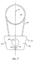
図7および図8を参照すると、本発明の第2実施形態が示されている。ここに示す連続ループチェーン駆動装置は、いくつかの内燃機関設計に必要であり得るもののような、バランスシャフトシステムである。しかしながら、本実施形態を、駆動軸が少なくとも1つのカムシャフトに連結されるタイミングシステム等の動力伝達駆動システムで使用してもよい、ということが理解されるべきである。特に図7を参照すると、テンショナ310はブラケット312を含む。外面314は、このシステムのバランスシャフト等のシャフトのうちの1つのスプロケット(図示せず)を覆う。外面314の隆起部345が、スプロケットを収容するためにブラケット312の下に空間を提供する。図8を参照すると、本実施形態のボルト、ピンまたはリベット等の枢支取付具319が、スプロケットのテンショナ221および221’とは反対側の枢支穴318に位置している。構造リブ316が溝322’から溝322を分離する。チェーン200の一方のストランドが、各溝322および322’内を走行する。第1実施形態と同様に、重要な設計特徴は、枢支穴318が、実質的に二等辺三角形を形成するように、緊張装置221および221’の各々の長さに沿ったおよそ中間点から実質的に等距離に位置する、ということである。枢支取付具319は、2つのスプロケットの軸の間の擬似垂直中心線217に沿って位置することが好ましい。第1実施形態に関して上述したように、枢支取付具319もまた減衰を提供する。
Referring to FIGS. 7 and 8, a second embodiment of the present invention is shown. The continuous loop chain drive shown here is a balanced shaft system, such as may be necessary for some internal combustion engine designs. However, it should be understood that this embodiment may be used in a power transmission drive system such as a timing system in which the drive shaft is coupled to at least one camshaft. With particular reference to FIG. 7, the
動力伝達タイミングシステムかまたはバランスシャフトシステムのいずれであっても、スプロケットの各々は、前進運動を維持しながら他方から独立して加速し減速する。駆動スプロケットが加速するか、または従動スプロケットが減速するとき、そこにわたっているストランドにおいてエネルギー波が形成され、減速したスプロケットから発して他方のスプロケットに向かって移動する。チェーンは、エネルギー波の開始スプロケットに噛み合うチェーンのリンクから他方のスプロケットに噛み合うチェーンのリンクまでの距離を、あり得る最短距離、すなわち直線でわたるようにする。エネルギーは、テンショナのチェーン摺動面の端部に達するまで、チェーンの自由ストランドを一度に1リンクで移動し、そのテンショナは、エネルギー波によって影響を受け、ストランドから離れる方向に枢動することによって強制的にそのエネルギーを吸収し、他方のテンショナは、他方のストランド内に枢動することにより、エネルギー波によってもたらされる弛みを巻き取り、それにより、チェーンの長さにわたって荷重を平衡化する。 Either the power transmission timing system or the balance shaft system, each of the sprockets accelerates and decelerates independently of the other while maintaining forward motion. As the drive sprocket accelerates or the driven sprocket decelerates, energy waves are formed in the strands across it, moving from the decelerated sprocket and moving toward the other sprocket. The chain causes the distance from the link of the chain that engages the starting sprocket of the energy wave to the link of the chain that engages the other sprocket to be the shortest possible distance, i.e. a straight line. The energy travels one chain at a time through the free strand of the chain until it reaches the end of the chain sliding surface of the tensioner, and the tensioner is affected by the energy wave and pivots away from the strand. The energy is forced to be absorbed, and the other tensioner pivots into the other strand to take up the slack caused by the energy wave and thereby balance the load over the length of the chain.
テンショナブラケット212または312は、特定の実施形態により、チェーン波エネルギーに応じてそのそれぞれの枢支穴を中心に枢動する。たとえば、緊張装置221’は、チェーンの隣接するストランドの緊張が増大することによってより高い力を受けている場合、強制的にチェーンから離れる傾向がある。ブラケットの枢動動作により、他方の緊張装置221が、強制的にチェーンの緩んだストランド方向に付勢し、閉ループチェーンシステムにおける緊張荷重全体が均衡を平衡化することができる。
The
内燃機関の停止中に発生する可能性のある捩りまたは逆回転による荷重反転の場合、緩みストランドと張りストランドとが反転し、テンショナ210または310は緩みストランドに張力をかけることによって応答し、それにより、通常のチェーン回転が再開されるまで、従動スプロケットにおけるチェーンの束化および歯飛びの可能性が防止される。2つの緊張装置221および221’およびそれぞれのテンショナブラケット212または312の枢支取付具219または319の三角形構成により、チェーン緊張の過度な変動の時にチェーン200の実質的に一様な緊張がもたらされる。
In the case of a load reversal due to torsion or counter-rotation that can occur while the internal combustion engine is stopped, the slack strands and tension strands are reversed, and the
したがって、本明細書で説明した本発明の実施形態は、本発明の原理の適用を単に例示するものであるということが理解される。本明細書における例示した実施形態の詳細に対する言及は、特許請求の範囲を限定するようには意図されておらず、特許請求の範囲自体が、本発明に必須であるとみなされる特徴を列挙している。 Accordingly, it is understood that the embodiments of the invention described herein are merely illustrative of the application of the principles of the present invention. References to details of illustrated embodiments herein are not intended to limit the scope of the claims, and the claims themselves enumerate features that are considered essential to this invention. ing.
Claims (15)
a)外面(214、314)および内面(215)を有するブラケット(212、312)と、
b)前記ブラケット(212、312)の前記内面(215)の第1溝(222、322)に位置する第1緊張装置(221)であって、前記第1溝(222、322)が、前記内面(215)の構造リブ(216、316)と第1溝壁(224)との間に位置し、第1可撓性チェーンガイド要素(220)が、長手方向チェーン摺動面(230)と、前記第1溝壁(224)に面する、前記チェーン摺動面(230)に対向する前記可撓性チェーンガイド要素(220)の内面(235)と、前記可撓性チェーンガイド要素(220)のフック型近位端(232)と、前記可撓性チェーンガイド要素(220)のフック型遠位端(233)と、を有し、前記フック型近位端(232)が、前記第1溝(222、322)の近位凹部(236)内で突起の周囲に半永久的に係合され、前記フック型遠位端(233)が、前記第1溝(222、322)の遠位凹部(238)内で突起の周囲に半永久的に係合される、第1緊張装置と、
c)第2溝(222’、322’)に配置される第2緊張装置(221’)であって、前記第2溝(222’、322’)が、前記ブラケット(212、312)の前記内面(215)の前記構造リブ(216、316)と第2溝壁(224’)との間に位置し、第2可撓性チェーンガイド要素(220’)が、長手方向チェーン摺動面(230’)と、前記第2溝壁(224’)に面する、前記チェーン摺動面(230’)に対向する前記可撓性チェーンガイド要素(220’)の内面(235’)と、前記可撓性チェーンガイド要素(220’)のフック型近位端(232’)と、前記可撓性チェーンガイド要素(220’)のフック型遠位端(233’)と、を有し、前記フック型近端(232’)が、前記第2溝(222’、322’)の近位凹部(236’)内で突起の周囲に半永久的に係合され、前記フック型遠位端(233’)が、前記第2溝(222’、322’)の遠位凹部(238’)内で突起の周囲に半永久的に係合される、第2緊張装置と、
d)前記ブラケット(212、312)をエンジンハウジングに固定する単一枢支取付具(219、319)であって、前記第1可撓性チェーンガイド要素(221)の前記長手方向チェーン摺動面(230)に沿ったおよそ中間点と、前記第2チェーンガイド要素(221’)の前記長手方向チェーン摺動面(230’)に沿ったおよそ中間点と、から、等距離に配置される、単一枢支取付具(219、319)と、
を備える、テンショナ。 In a closed loop chain drive system for an internal combustion engine having a drive sprocket (202) operably connected to a drive shaft and at least one driven sprocket (204) operably connected to at least one driven shaft. Tensioners (210, 310) that apply tension to the chain (200),
a) brackets (212, 312) having an outer surface (214, 314) and an inner surface (215);
b) a first tensioning device (221) located in a first groove (222, 322) of the inner surface (215) of the bracket (212, 312), wherein the first groove (222, 322) is Located between the structural ribs (216, 316) of the inner surface (215) and the first groove wall (224), the first flexible chain guide element (220) is connected to the longitudinal chain sliding surface (230). An inner surface (235) of the flexible chain guide element (220) facing the first groove wall (224) and facing the chain sliding surface (230); and the flexible chain guide element (220). ) Hook-type proximal end (232) and the flexible chain guide element (220) hook-type distal end (233), the hook-type proximal end (232) being Proximal recess (236) of one groove (222, 322) And the hook-type distal end (233) is semi-permanently engaged around the protrusion within the distal recess (238) of the first groove (222, 322). Combined with a first tensioning device;
c) a second tensioning device (221 ′) disposed in a second groove (222 ′, 322 ′), wherein the second groove (222 ′, 322 ′) is a part of the bracket (212, 312); Located between the structural ribs (216, 316) and the second groove wall (224 ′) of the inner surface (215), the second flexible chain guide element (220 ′) is a longitudinal chain sliding surface ( 230 ′), the inner surface (235 ′) of the flexible chain guide element (220 ′) facing the second sliding wall (224 ′) and facing the chain sliding surface (230 ′), A hook-type proximal end (232 ') of the flexible chain guide element (220') and a hook-type distal end (233 ') of the flexible chain guide element (220'); A hook-type proximal end (232 ′) is a proximal recess (236 ′) of the second groove (222 ′, 322 ′). And the hook-shaped distal end (233 ') is semi-permanently around the protrusion within the distal recess (238') of the second groove (222 ', 322'). A second tensioning device,
d) a single pivot attachment (219, 319) for securing the bracket (212, 312) to the engine housing, the longitudinal chain sliding surface of the first flexible chain guide element (221); Approximately equidistant from the intermediate point along (230) and approximately the intermediate point along the longitudinal chain sliding surface (230 ′) of the second chain guide element (221 ′). A single pivot attachment (219, 319);
A tensioner.
前記枢支取付具(219、319)と、各チェーンガイド要素(220、220’)の各チェーン摺動面(230、230’)の各中間点と、が、実質的に二等辺三角形を形成する、テンショナ。 The tensioner according to claim 1, wherein
The pivot support (219, 319) and the midpoint of each chain sliding surface (230, 230 ') of each chain guide element (220, 220') substantially form an isosceles triangle. Tensioner.
前記枢支取付具(219、319)が、前記閉ループチェーン駆動システムの周辺部内の前記駆動スプロケット(202)と前記少なくとも1つの従動スプロケット(204)との間に位置する、テンショナ。 A tensioner according to claim 2, wherein
A tensioner, wherein the pivot fitting (219, 319) is located between the drive sprocket (202) and the at least one driven sprocket (204) in the periphery of the closed loop chain drive system.
前記枢支取付具(219、319)が、前記駆動スプロケット(202)の下方かつ前記閉ループチェーン駆動システムの周辺部外に位置する、テンショナ。 A tensioner according to claim 2, wherein
A tensioner in which the pivot fitting (219, 319) is located below the drive sprocket (202) and outside the periphery of the closed loop chain drive system.
前記従動シャフトがカムシャフトである、テンショナ。 The tensioner according to claim 1, wherein
A tensioner, wherein the driven shaft is a camshaft.
前記従動シャフトがバランスシャフトである、テンショナ。 The tensioner according to claim 1, wherein
A tensioner, wherein the driven shaft is a balance shaft.
前記第1可撓性チェーンガイド要素(220)の前記チェーン摺動面(230)が、前記チェーン(200)の第1ストランドに、その長手方向面に沿って強制的に係合し、前記第2可撓性チェーンガイド要素(220’)の前記チェーン摺動面(230’)が、前記チェーン(200)の第2ストランドに、その長手方向面に沿って強制的に係合する、テンショナ。 The tensioner according to claim 1, wherein
The chain sliding surface (230) of the first flexible chain guide element (220) is forcibly engaged with the first strand of the chain (200) along its longitudinal surface, 2 A tensioner in which the chain sliding surface (230 ') of the flexible chain guide element (220') is forcibly engaged with the second strand of the chain (200) along its longitudinal surface.
前記第1溝壁(222、322)と前記第1チェーンガイド要素(221)の前記内面(235)との間に配置された少なくとも1つのブレードスプリング(240)をさらに備える、テンショナ。 The tensioner according to claim 1, wherein
A tensioner further comprising at least one blade spring (240) disposed between the first groove wall (222, 322) and the inner surface (235) of the first chain guide element (221).
前記第2溝壁(222’、322’)と前記第2チェーンガイド要素(221’)の前記内面(235’)との間に配置された少なくとも1つのブレードスプリング(240’)をさらに備える、テンショナ。 The tensioner according to claim 1, wherein
And at least one blade spring (240 ′) disposed between the second groove wall (222 ′, 322 ′) and the inner surface (235 ′) of the second chain guide element (221 ′). Tensioner.
前記第1溝壁(222、322)と前記第1チェーンガイド要素(221)の前記内面(235)との間に配置された少なくとも1つのブレードスプリング(240)と、前記第2溝壁(222’、322’)と前記第2チェーンガイド要素(221’)の前記内面(235’)との間に配置された少なくとも1つのブレードスプリング(240’)と、をさらに備える、テンショナ。 The tensioner according to claim 1, wherein
At least one blade spring (240) disposed between the first groove wall (222, 322) and the inner surface (235) of the first chain guide element (221); and the second groove wall (222). ', 322') and at least one blade spring (240 ') disposed between the inner surface (235') of the second chain guide element (221 ').
前記枢支取付具(219、319)が、捩り減衰を含む、テンショナ。 The tensioner according to claim 1, wherein
A tensioner wherein the pivot fitting (219, 319) includes torsional damping.
前記枢支取付具(219、319)が、前記駆動スプロケット(202)の軸と前記従動スプロケット(204)の軸との間に形成された仮想垂直中心線に位置する、テンショナ。 The tensioner according to claim 1, wherein
A tensioner in which the pivot fixture (219, 319) is located on a virtual vertical centerline formed between the axis of the drive sprocket (202) and the axis of the driven sprocket (204).
前記枢支取付具(219、319)が、前記閉ループチェーン駆動システムの前記周辺部内の前記駆動スプロケット(202)と前記従動スプロケット(204)との間に位置する、テンショナ。 A tensioner according to claim 12,
A tensioner in which the pivot fitting (219, 319) is located between the drive sprocket (202) and the driven sprocket (204) in the periphery of the closed loop chain drive system.
前記枢支取付具(219、319)が、前記閉ループチェーン駆動システムの前記周辺部の外側に位置する、テンショナ。 A tensioner according to claim 12,
A tensioner in which the pivot attachment (219, 319) is located outside the periphery of the closed loop chain drive system.
前記枢支取付具(219、319)が前記駆動スプロケット(202)または前記従動スプロケット(204)の下方に位置する、テンショナ。 The tensioner according to claim 14, wherein
A tensioner in which the pivot attachment (219, 319) is located below the drive sprocket (202) or the driven sprocket (204).
Applications Claiming Priority (3)
| Application Number | Priority Date | Filing Date | Title |
|---|---|---|---|
| US11/382,730 | 2006-05-11 | ||
| US11/382,730 US7537533B2 (en) | 2003-10-15 | 2006-05-11 | Chain tensioning device linking two strands of a chain drive |
| PCT/US2007/067727 WO2007133919A1 (en) | 2006-05-11 | 2007-04-30 | Chain tensioning device linking two strands of a chain drive |
Publications (2)
| Publication Number | Publication Date |
|---|---|
| JP2009537000A JP2009537000A (en) | 2009-10-22 |
| JP5227954B2 true JP5227954B2 (en) | 2013-07-03 |
Family
ID=38515672
Family Applications (1)
| Application Number | Title | Priority Date | Filing Date |
|---|---|---|---|
| JP2009509983A Expired - Fee Related JP5227954B2 (en) | 2006-05-11 | 2007-04-30 | Chain tensioning device that connects two strands of chain drive |
Country Status (7)
| Country | Link |
|---|---|
| US (1) | US7537533B2 (en) |
| EP (1) | EP2016307B1 (en) |
| JP (1) | JP5227954B2 (en) |
| KR (1) | KR101318131B1 (en) |
| CN (1) | CN101438080B (en) |
| DE (1) | DE602007001888D1 (en) |
| WO (1) | WO2007133919A1 (en) |
Families Citing this family (14)
| Publication number | Priority date | Publication date | Assignee | Title |
|---|---|---|---|---|
| DE202006012966U1 (en) * | 2006-08-23 | 2007-12-27 | JOH. WINKLHOFER & SÖHNE GMBH & Co. KG | Clamping rail for a chain drive with a bridging guide channel section as pressing area |
| JP5166473B2 (en) * | 2010-03-31 | 2013-03-21 | ジヤトコ株式会社 | Chain type continuously variable transmission and assembly method thereof |
| WO2012030702A1 (en) * | 2010-08-30 | 2012-03-08 | Cloyes Gear And Products, Inc. | Blade tensioner and bracket for blade tensioner including pocket pivot feature |
| US20130150192A1 (en) * | 2011-12-09 | 2013-06-13 | Chrysler Group Llc | Compliant guide device |
| CN104662333B (en) * | 2012-07-17 | 2016-08-10 | 舍弗勒技术股份两合公司 | For boring the guiding mechanism of the band device of dribbling actuating device |
| DE102013106930B3 (en) * | 2013-07-02 | 2014-06-26 | Pierburg Gmbh | Traction mechanism and camshaft actuator with such Zugmittelgetriebe |
| DE102015008877A1 (en) * | 2015-07-08 | 2016-08-04 | Iwis Motorsysteme Gmbh & Co. Kg | Modular sliding or tensioning rail |
| US10156290B2 (en) * | 2015-02-06 | 2018-12-18 | FLIR Belgium BVBA | Belt drive tensioning system |
| CN107407380A (en) * | 2015-03-09 | 2017-11-28 | 克劳伊斯传动装置产品有限公司 | There is the chain tensioning device plastic blade of improved structural rigidity in the spring end reaction surface of blade |
| JP6906840B2 (en) * | 2017-04-07 | 2021-07-21 | 株式会社椿本チエイン | Chain guide mechanism |
| US20200116124A1 (en) * | 2018-10-12 | 2020-04-16 | Gates Corporation | Wind Turbine Belt Drive Pitch Control |
| EP3931467A1 (en) * | 2019-02-25 | 2022-01-05 | BorgWarner Sweden AB | Chain tensioning of a hybrid drive module |
| JP2022109518A (en) * | 2021-01-15 | 2022-07-28 | 株式会社椿本チエイン | Chain guide mechanism |
| CN114012979A (en) * | 2021-12-01 | 2022-02-08 | 伊维氏传动系统(平湖)有限公司 | Guide rail assembly process and structure |
Family Cites Families (23)
| Publication number | Priority date | Publication date | Assignee | Title |
|---|---|---|---|---|
| JPS5256180U (en) * | 1975-10-20 | 1977-04-22 | ||
| US4069719A (en) | 1976-06-18 | 1978-01-24 | Cancilla Philip S | Chain tensioner for chain drives |
| JPS5466071U (en) * | 1977-10-19 | 1979-05-10 | ||
| JPS5745484Y2 (en) * | 1978-06-07 | 1982-10-06 | ||
| IT1135351B (en) * | 1981-02-06 | 1986-08-20 | Catene Calibrate Regina | TENSIONER FOR TRANSMISSION BODIES OF A MOTORCYCLE, SUCH AS ROLLER CHAINS, BELTS AND SIMILAR |
| DE3326319A1 (en) | 1983-07-21 | 1985-01-31 | Dr.Ing.H.C. F. Porsche Ag, 7000 Stuttgart | CHAIN DRIVE OF A PISTON PISTON INTERNAL COMBUSTION ENGINE |
| US4869708A (en) * | 1988-04-15 | 1989-09-26 | Borg-Warner Transmission And Engine Components Corporation | Sprocket retention/chain guide assembly |
| US5221236A (en) | 1990-07-10 | 1993-06-22 | Raymer Matthew C | Belt tensioning device for belt driven bicycle |
| DE19536643A1 (en) | 1995-09-30 | 1997-04-03 | Schaeffler Waelzlager Kg | Clamping device for a control drive |
| DE19607819A1 (en) * | 1996-03-01 | 1997-09-04 | Bayerische Motoren Werke Ag | Chain drive unit for the camshaft drive of an internal combustion engine |
| US5797818A (en) * | 1996-04-02 | 1998-08-25 | Cloyes Gear And Products, Inc. | Chain tensioner with damping feature |
| EP0892193A1 (en) | 1997-07-14 | 1999-01-20 | Morse Tec Europe S.p.A. | A device for take-up of tolerance in a chain drive |
| JP3113224B2 (en) | 1997-10-14 | 2000-11-27 | 株式会社椿本チエイン | Tensioner guide |
| US6155941A (en) * | 1998-12-15 | 2000-12-05 | Borgwarner Inc. | Hydraulic tensioner having a flexible blade arm |
| US6358169B1 (en) * | 2000-05-02 | 2002-03-19 | Borgwarner Inc. | Chain tensioner system having a pivoting tensioner arm |
| US6322470B1 (en) | 2000-05-17 | 2001-11-27 | Borgwarner Inc. | Pivoting dual arm chain tensioner system for contacting multiple chain strands |
| JP2002039295A (en) * | 2000-07-26 | 2002-02-06 | Nissan Motor Co Ltd | Ratchet type tensioner |
| WO2002033288A2 (en) * | 2000-10-17 | 2002-04-25 | Cloyes Gear And Products, Inc. | Blade-type mechanical chain tensioner with external strengthening rib |
| JP2003074652A (en) | 2001-08-31 | 2003-03-12 | Daido Steel Co Ltd | Tensioner |
| DE20120656U1 (en) * | 2001-12-20 | 2003-04-30 | Winklhofer & Soehne Gmbh | Pre-assembled propellant unit |
| JP3926182B2 (en) * | 2002-03-27 | 2007-06-06 | 株式会社椿本チエイン | Ratchet hydraulic tensioner |
| US6945889B2 (en) * | 2002-10-04 | 2005-09-20 | Borgwarner Inc. | Hydraulic chain tensioner |
| US7097579B2 (en) * | 2003-10-15 | 2006-08-29 | Borgwarner Inc. | Pivoting chain guide and tensioner assembly |
-
2006
- 2006-05-11 US US11/382,730 patent/US7537533B2/en active Active
-
2007
- 2007-04-30 JP JP2009509983A patent/JP5227954B2/en not_active Expired - Fee Related
- 2007-04-30 KR KR1020087028438A patent/KR101318131B1/en active IP Right Grant
- 2007-04-30 WO PCT/US2007/067727 patent/WO2007133919A1/en active Application Filing
- 2007-04-30 DE DE602007001888T patent/DE602007001888D1/en active Active
- 2007-04-30 EP EP07761542A patent/EP2016307B1/en active Active
- 2007-04-30 CN CN2007800165591A patent/CN101438080B/en not_active Expired - Fee Related
Also Published As
| Publication number | Publication date |
|---|---|
| WO2007133919A1 (en) | 2007-11-22 |
| EP2016307A1 (en) | 2009-01-21 |
| JP2009537000A (en) | 2009-10-22 |
| DE602007001888D1 (en) | 2009-09-17 |
| CN101438080A (en) | 2009-05-20 |
| KR20090007603A (en) | 2009-01-19 |
| US20060247080A1 (en) | 2006-11-02 |
| EP2016307B1 (en) | 2009-08-05 |
| KR101318131B1 (en) | 2013-10-16 |
| CN101438080B (en) | 2011-08-24 |
| US7537533B2 (en) | 2009-05-26 |
Similar Documents
| Publication | Publication Date | Title |
|---|---|---|
| JP5227954B2 (en) | Chain tensioning device that connects two strands of chain drive | |
| US7476168B2 (en) | Pivoting mechanical tensioner with cross strand damping | |
| US7479077B2 (en) | Pivoting mechanical tensioner with compliant blade spring | |
| EP2057389B1 (en) | Two way damper | |
| US7641577B2 (en) | Mechanical chain tensioner with compliant blade spring | |
| US8066600B2 (en) | Ratchet mechanism for a chain drive | |
| US7597640B2 (en) | Long mechanical tensioner with a compliant blade spring | |
| US6849015B2 (en) | Ratcheting pivot arm tensioner with backlash | |
| US8025599B2 (en) | Pivot arm tensioner with sliding ratchet mechanism |
Legal Events
| Date | Code | Title | Description |
|---|---|---|---|
| A621 | Written request for application examination |
Free format text: JAPANESE INTERMEDIATE CODE: A621 Effective date: 20100119 |
|
| A977 | Report on retrieval |
Free format text: JAPANESE INTERMEDIATE CODE: A971007 Effective date: 20120613 |
|
| A131 | Notification of reasons for refusal |
Free format text: JAPANESE INTERMEDIATE CODE: A131 Effective date: 20120619 |
|
| TRDD | Decision of grant or rejection written | ||
| A01 | Written decision to grant a patent or to grant a registration (utility model) |
Free format text: JAPANESE INTERMEDIATE CODE: A01 Effective date: 20130219 |
|
| A61 | First payment of annual fees (during grant procedure) |
Free format text: JAPANESE INTERMEDIATE CODE: A61 Effective date: 20130318 |
|
| R150 | Certificate of patent or registration of utility model |
Ref document number: 5227954 Country of ref document: JP Free format text: JAPANESE INTERMEDIATE CODE: R150 Free format text: JAPANESE INTERMEDIATE CODE: R150 |
|
| FPAY | Renewal fee payment (event date is renewal date of database) |
Free format text: PAYMENT UNTIL: 20160322 Year of fee payment: 3 |
|
| R250 | Receipt of annual fees |
Free format text: JAPANESE INTERMEDIATE CODE: R250 |
|
| R250 | Receipt of annual fees |
Free format text: JAPANESE INTERMEDIATE CODE: R250 |
|
| R250 | Receipt of annual fees |
Free format text: JAPANESE INTERMEDIATE CODE: R250 |
|
| R250 | Receipt of annual fees |
Free format text: JAPANESE INTERMEDIATE CODE: R250 |
|
| LAPS | Cancellation because of no payment of annual fees |