JP5225747B2 - Electric vehicle and battery control device storage method - Google Patents
Electric vehicle and battery control device storage method Download PDFInfo
- Publication number
- JP5225747B2 JP5225747B2 JP2008128434A JP2008128434A JP5225747B2 JP 5225747 B2 JP5225747 B2 JP 5225747B2 JP 2008128434 A JP2008128434 A JP 2008128434A JP 2008128434 A JP2008128434 A JP 2008128434A JP 5225747 B2 JP5225747 B2 JP 5225747B2
- Authority
- JP
- Japan
- Prior art keywords
- battery
- control device
- vehicle
- center tunnel
- battery control
- Prior art date
- Legal status (The legal status is an assumption and is not a legal conclusion. Google has not performed a legal analysis and makes no representation as to the accuracy of the status listed.)
- Expired - Fee Related
Links
Images


Classifications
-
- Y—GENERAL TAGGING OF NEW TECHNOLOGICAL DEVELOPMENTS; GENERAL TAGGING OF CROSS-SECTIONAL TECHNOLOGIES SPANNING OVER SEVERAL SECTIONS OF THE IPC; TECHNICAL SUBJECTS COVERED BY FORMER USPC CROSS-REFERENCE ART COLLECTIONS [XRACs] AND DIGESTS
- Y02—TECHNOLOGIES OR APPLICATIONS FOR MITIGATION OR ADAPTATION AGAINST CLIMATE CHANGE
- Y02E—REDUCTION OF GREENHOUSE GAS [GHG] EMISSIONS, RELATED TO ENERGY GENERATION, TRANSMISSION OR DISTRIBUTION
- Y02E60/00—Enabling technologies; Technologies with a potential or indirect contribution to GHG emissions mitigation
- Y02E60/30—Hydrogen technology
- Y02E60/50—Fuel cells
-
- Y—GENERAL TAGGING OF NEW TECHNOLOGICAL DEVELOPMENTS; GENERAL TAGGING OF CROSS-SECTIONAL TECHNOLOGIES SPANNING OVER SEVERAL SECTIONS OF THE IPC; TECHNICAL SUBJECTS COVERED BY FORMER USPC CROSS-REFERENCE ART COLLECTIONS [XRACs] AND DIGESTS
- Y02—TECHNOLOGIES OR APPLICATIONS FOR MITIGATION OR ADAPTATION AGAINST CLIMATE CHANGE
- Y02T—CLIMATE CHANGE MITIGATION TECHNOLOGIES RELATED TO TRANSPORTATION
- Y02T10/00—Road transport of goods or passengers
- Y02T10/60—Other road transportation technologies with climate change mitigation effect
- Y02T10/70—Energy storage systems for electromobility, e.g. batteries
Landscapes
- Arrangement Or Mounting Of Propulsion Units For Vehicles (AREA)
- Battery Mounting, Suspending (AREA)
- Electric Propulsion And Braking For Vehicles (AREA)
- Fuel Cell (AREA)
Description
本発明は、電気自動車に関する。詳しくは、バッテリボックスおよびバッテリ制御装置が車両のフロアパネルよりも下方に配置された電気自動車に関する。 The present invention relates to an electric vehicle. More specifically, the present invention relates to an electric vehicle in which a battery box and a battery control device are disposed below a vehicle floor panel.
従来より、車輪を駆動する駆動モータと、この駆動モータに電力を供給するバッテリと、このバッテリを制御する制御装置と、を備えた電気自動車が知られている。
この電気自動車では、車両の車室内のスペースを広く確保するとともに、車両の乗員の安全性を向上させるために、バッテリを車室の床面を構成するフロアパネルよりも下方の車室外に配置することが提案されている(例えば、特許文献1参照)。このような電気自動車では、バッテリとともに、このバッテリを制御するバッテリ制御装置もフロアパネルよりも下方に配置される。
2. Description of the Related Art Conventionally, an electric vehicle including a drive motor that drives wheels, a battery that supplies electric power to the drive motor, and a control device that controls the battery is known.
In this electric vehicle, in order to secure a wide space in the vehicle interior of the vehicle and improve the safety of the vehicle occupant, the battery is disposed outside the vehicle compartment below the floor panel constituting the floor surface of the vehicle interior. Has been proposed (see, for example, Patent Document 1). In such an electric vehicle, a battery control device for controlling the battery is also disposed below the floor panel together with the battery.
特許文献1で提案された電気自動車によれば、バッテリ制御装置をバッテリとともにフロアパネルよりも下方に配置したので、バッテリとバッテリ制御装置とを接続する接続ハーネスを短くして、接続ハーネスで発生するノイズを低減でき、その結果、バッテリ制御装置に対するノイズの影響を軽減できる。
しかしながら、特許文献1で提案された電気自動車では、バッテリ制御装置がフロアパネルよりも下方に配置されているため、濡れた路面を車両が走行すると、車輪により水や水滴が跳ね上げられて、この跳ね上げられた水や水滴が車体内部に浸入し、このバッテリ制御装置に水や水滴が付着する、という問題があった。
However, in the electric vehicle proposed in
本発明は、バッテリ制御装置に水や水滴が付着するのを抑制でき、かつ、このバッテリ制御装置に対するノイズの影響を軽減できる電気自動車を提供することを目的とする。 An object of this invention is to provide the electric vehicle which can suppress that water and a water droplet adhere to a battery control apparatus, and can reduce the influence of the noise with respect to this battery control apparatus.
本発明の電気自動車(例えば、後述の燃料電池車両1)は、駆動モータに電力を供給するバッテリ(例えば、後述のバッテリ21)と、当該バッテリを収納するバッテリボックス(例えば、後述のバッテリボックス22)と、前記バッテリの充放電状態を制御するバッテリ制御装置(例えば、後述のバッテリ制御装置23)と、前記バッテリボックスと前記バッテリ制御装置とを接続する接続ハーネス(例えば、後述の接続ハーネス24)と、を備え、前記バッテリボックスおよび前記バッテリ制御装置は、フロアパネル(例えば、後述のフロアパネル40)よりも下方に配置される電気自動車であって、前記フロアパネルは、上方に突出して形成されたセンタートンネル部(例えば、後述のセンタートンネル部42)と、当該センタートンネル部の両側から外方に延出するフロア部(例えば、後述のフロア部41)と、で構成され、前記バッテリ制御装置は、前記バッテリボックスの上面に固定されて、かつ、前記センタートンネル部内に収納され、前記バッテリボックスは、前記フロア部に亘って配置され、前記センタートンネル部を下方から覆い、前記接続ハーネスは、前記バッテリ制御装置の車両後方側と前記バッテリボックスの車両後方側とを接続することを特徴とする。
An electric vehicle (for example, a
この発明によれば、バッテリ制御装置をバッテリボックスの上面に固定してセンタートンネル部内に収納するとともに、このバッテリボックスでセンタートンネル部を下方から覆った。これにより、車体内部に浸入した水や水滴は、バッテリボックスに遮られて、バッテリ制御装置まで到達しない。よって、バッテリ制御装置に水や水滴が付着するのを防止するために、別途遮蔽板を設ける必要がなく、簡単な構成でバッテリ制御装置に水や水滴が付着するのを抑制できる。
また、バッテリボックスにより、水や水滴だけでなく跳ね上げられた小石や砂などの異物も遮蔽できるので、これらの異物が衝突することによりバッテリ制御装置が破損するのを防止できる。
According to the present invention, the battery control device is fixed to the upper surface of the battery box and accommodated in the center tunnel portion, and the center tunnel portion is covered with the battery box from below. Thereby, the water and water droplets that have entered the vehicle body are blocked by the battery box and do not reach the battery control device. Therefore, in order to prevent water and water droplets from adhering to the battery control device, it is not necessary to provide a separate shielding plate, and it is possible to suppress water and water droplets from adhering to the battery control device with a simple configuration.
In addition, since the battery box can shield not only water and water droplets but also foreign objects such as pebbles and sand that are splashed up, the battery control device can be prevented from being damaged by collision of these foreign objects.
また、バッテリ制御装置をセンタートンネル部で覆ったので、センタートンネル部がバッテリ制御装置を遮蔽することになり、バッテリ制御装置に対するノイズの影響を軽減できる。 Further, since the battery control device is covered with the center tunnel portion, the center tunnel portion shields the battery control device, and the influence of noise on the battery control device can be reduced.
また、車両が走行すると、車輪により跳ね上げられた水や水滴は、車両後方側に向かって移動することになる。
そこで、この発明によれば、バッテリ制御装置の車両後方側とバッテリボックスの車両後方側とを接続ハーネスで接続した。よって、跳ね上げられた水や水滴が接続ハーネスに付着するのを抑制でき、接続ハーネスが被水するのを防止できる。
Further, when the vehicle travels, water and water droplets splashed by the wheels move toward the vehicle rear side.
Therefore, according to the present invention, the vehicle rear side of the battery control device and the vehicle rear side of the battery box are connected by the connection harness. Therefore, it is possible to suppress the splashed water and water droplets from adhering to the connection harness, and to prevent the connection harness from getting wet.
また、センタートンネル部内にバッテリ制御装置を収納したので車室内のスペースを広く確保できる。
また、バッテリ制御装置をバッテリとともにフロアパネルよりも下方の車室外に配置して、バッテリ制御装置とバッテリとを接続ハーネスで接続した。よって、接続ハーネスを短くできるので、構造を簡素化できるとともに、バッテリ制御装置に対するノイズの影響を軽減できる。
Further, since the battery control device is housed in the center tunnel portion, a large space in the vehicle compartment can be secured.
Moreover, the battery control device was disposed outside the vehicle compartment below the floor panel together with the battery, and the battery control device and the battery were connected by a connection harness. Therefore, since the connection harness can be shortened, the structure can be simplified and the influence of noise on the battery control device can be reduced.
この場合、前記バッテリは、複数のバッテリセル(例えば、後述のバッテリセル211)を備え、当該複数のバッテリセルのそれぞれの端子は、車両後方側を向いて配置されることが好ましい。
In this case, it is preferable that the battery includes a plurality of battery cells (for example, a
この発明によれば、複数のバッテリセルのそれぞれの端子を、車両後方側に向けて配置した。これにより、バッテリセルの端子と接続ハーネスとを車両後方側で容易に接続できるので、この接続ハーネスの防水対策を容易に行える。 According to this invention, each terminal of the plurality of battery cells is arranged toward the vehicle rear side. Thereby, since the terminal of a battery cell and a connection harness can be easily connected by the vehicle rear side, the waterproof measure of this connection harness can be performed easily.
この場合、前記バッテリボックスは、サブフレーム(例えば、後述のサブフレーム50)上に固定され、当該サブフレームは、車体を構成するフレーム(例えば、後述のフレーム60)に接続されることが好ましい。
In this case, it is preferable that the battery box is fixed on a subframe (for example, a
この発明によれば、バッテリボックスをサブフレーム上に固定し、このサブフレームを、車体を構成するフレームに接続した。このように、サブフレームを車体に接続することで、バッテリボックスを車体に容易に取り付けられるとともに、バッテリ制御装置を容易に防水できる。 According to the present invention, the battery box is fixed on the subframe, and the subframe is connected to the frame constituting the vehicle body. Thus, by connecting the sub frame to the vehicle body, the battery box can be easily attached to the vehicle body, and the battery control device can be easily waterproofed.
この場合、前記バッテリボックスの車両幅方向の両端部は、前記センタートンネル部の車両幅方向の両端部よりも外側に位置していることが好ましい。 In this case, it is preferable that both ends of the battery box in the vehicle width direction are located outside both ends of the center tunnel portion in the vehicle width direction.
この発明によれば、バッテリボックスの車両幅方向の両端部を、センタートンネル部の車両幅方向の両端部よりも外側に位置させた。これにより、センタートンネル部の下方は、このセンタートンネル部の車両幅方向の両端部間に亘ってバッテリボックスにより覆われる。よって、センタートンネル部の内部に水や水滴が侵入するのを確実に防止できるので、バッテリ制御装置の防水性をさらに向上できる。 According to the present invention, the both ends of the battery box in the vehicle width direction are positioned outside the both ends of the center tunnel portion in the vehicle width direction. Thereby, the lower part of a center tunnel part is covered with a battery box over the both ends of the vehicle width direction of this center tunnel part. Therefore, it is possible to reliably prevent water and water droplets from entering the center tunnel portion, so that the waterproofness of the battery control device can be further improved.
この場合、前記センタートンネル部の車両前方側および車両後方側のうち少なくとも一方には、前記バッテリ制御装置を遮蔽する遮蔽部(例えば、後述の遮蔽部70)が設けられることが好ましい。
In this case, it is preferable that at least one of the vehicle front side and the vehicle rear side of the center tunnel portion is provided with a shielding portion (for example, a
この発明によれば、前記センタートンネル部の車両前方側および車両後方側のうち少なくとも一方に遮蔽部を設けた。これにより、燃料電池などのセンタートンネル部の内部に設けられた高電圧機器でノイズが発生しても、このノイズは遮蔽部によって遮蔽されるので、バッテリ制御装置がノイズの影響を受けるのを抑制できる。
また、センタートンネル部の内部に水や水滴が侵入しても、これら水や水滴は、遮蔽部によって遮蔽されるので、バッテリ制御装置の防水性を向上できる。
According to this invention, the shielding part is provided on at least one of the vehicle front side and the vehicle rear side of the center tunnel part. As a result, even if noise is generated in a high-voltage device installed inside the center tunnel part such as a fuel cell, the noise is shielded by the shielding part, so that the battery control device is prevented from being affected by the noise. it can.
Even if water or water droplets enter the center tunnel portion, the water and water droplets are shielded by the shielding portion, so that the waterproofness of the battery control device can be improved.
この場合、前記遮蔽部は、前記フロアパネルの一部が湾曲されて形成されることが好ましい。 In this case, it is preferable that the shielding portion is formed by bending a part of the floor panel.
この場合、前記遮蔽部は、前記センタートンネル部に取り付けられた遮蔽板であることが好ましい。 In this case, the shielding part is preferably a shielding plate attached to the center tunnel part.
本発明のバッテリ制御装置収納方法は、駆動モータに電力を供給するバッテリ(例えば、後述のバッテリ21)と、当該バッテリを収納するバッテリボックス(例えば、後述のバッテリボックス22)と、前記バッテリの充放電状態を制御するバッテリ制御装置(例えば、後述のバッテリ制御装置23)と、前記バッテリボックスと前記バッテリ制御装置とを接続する接続ハーネス(例えば、後述の接続ハーネス24)と、を備える電気自動車について、前記バッテリ制御装置をフロアパネル(例えば、後述のフロアパネル40)よりも下方に配置するバッテリ制御装置収納方法であって、前記バッテリ制御装置を、前記バッテリボックスの上面に固定するとともに、前記フロアパネルに上方に突出して形成されたセンタートンネル部(例えば、後述のセンタートンネル部42)内に収納し、前記バッテリボックスを、前記センタートンネル部の両側から外方に延出するフロア部(例えば、後述のフロア部41)に亘って配置して、前記センタートンネル部を下方から覆い、前記接続ハーネスにより、前記バッテリ制御装置の車両後方側と前記バッテリボックスの車両後方側とを接続することを特徴とする。
The battery control device storage method of the present invention includes a battery (for example, a
この発明によれば、上述と同様の効果がある。 According to the present invention, there are the same effects as described above.
この発明によれば、バッテリ制御装置をバッテリボックスの上面に固定してセンタートンネル部内に収納するとともに、このバッテリボックスでセンタートンネル部を下方から覆った。これにより、車体内部に浸入した水や水滴は、バッテリボックスに遮られて、バッテリ制御装置まで到達しない。よって、バッテリ制御装置に水や水滴が付着するのを防止するために、別途遮蔽板を設ける必要がなく、簡単な構成でバッテリ制御装置に水や水滴が付着するのを抑制できる。また、バッテリボックスにより、水や水滴だけでなく跳ね上げられた小石や砂などの異物も遮蔽できるので、これらの異物が衝突することによりバッテリ制御装置が破損するのを防止できる。また、バッテリ制御装置をセンタートンネル部で覆ったので、センタートンネル部がバッテリ制御装置を遮蔽することになり、バッテリ制御装置に対するノイズの影響を軽減できる。 According to the present invention, the battery control device is fixed to the upper surface of the battery box and accommodated in the center tunnel portion, and the center tunnel portion is covered with the battery box from below. Thereby, the water and water droplets that have entered the vehicle body are blocked by the battery box and do not reach the battery control device. Therefore, in order to prevent water and water droplets from adhering to the battery control device, it is not necessary to provide a separate shielding plate, and it is possible to suppress water and water droplets from adhering to the battery control device with a simple configuration. In addition, since the battery box can shield not only water and water droplets but also foreign objects such as pebbles and sand that are splashed up, the battery control device can be prevented from being damaged by collision of these foreign objects. Further, since the battery control device is covered with the center tunnel portion, the center tunnel portion shields the battery control device, and the influence of noise on the battery control device can be reduced.
以下、本発明の各実施形態を図面に基づいて説明する。
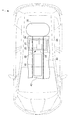
図1は、本発明の一実施形態に係る電気自動車が適用された燃料電池車両1の概略構成を示す車両長さ方向の縦断面図であり、図2は、燃料電池車両1の横断面図である。
Hereinafter, each embodiment of the present invention will be described with reference to the drawings.
FIG. 1 is a longitudinal sectional view in the vehicle length direction showing a schematic configuration of a
燃料電池車両1は、燃料電池10と、この燃料電池10の後方に配置されるバッテリシステム20と、このバッテリシステム20の後方に配置され燃料電池10に供給する水素ガスを貯留する水素タンク30と、を備える。
The
これら燃料電池10およびバッテリシステム20は、燃料電池車両1の車室の床となるフロアパネル40よりも下方、すなわち車室外に設けられる。
具体的には、フロアパネル40には、センタートンネル43が形成されている。燃料電池10は、車両の前後方向に長い箱状であり、フロアパネル40のセンタートンネル43に収容されている。また、バッテリシステム20の一部は、フロアパネル40のセンタートンネル43の燃料電池10よりも後方に収容されている。
The
Specifically, a
この燃料電池10には、図示しない反応ガス供給装置により、アノード電極(陽極)側に水素タンク30から水素ガスが供給され、カソード電極(陰極)側に酸素を含むエアが供給されると、電気化学反応により発電する。この燃料電池10で発電した電力により、図示しない駆動モータを駆動して、燃料電池車両1を走行させる。
When this
図3は、バッテリシステム20の斜視図であり、図4は、バッテリシステム20の上面図である。図5は、バッテリシステム20の側面図である。
バッテリシステム20は、バッテリ21と、このバッテリ21を収納する箱状のバッテリボックス22と、このバッテリボックス22の上面に配置される箱状のバッテリ制御装置23と、を備える。
FIG. 3 is a perspective view of the
The
バッテリ21は、燃料電池10で発電した電力や、減速時における駆動モータからの回生電力などを蓄電する。また、このバッテリ21に蓄電された電力は、運転状態に応じて駆動モータに適宜供給される。
バッテリボックス22は、車両の幅方向に長い形状である。
The
The
バッテリ21は、図5に示すように、複数の円筒状のバッテリセル211を備えており、これらバッテリセル211は、正極端子が車両の後方側を向いた状態で、車両の前後方向に沿って配置されている。
バッテリボックス22の後面側には、端子板221が収納されており、これらバッテリセル211のうち最後方に位置するものの正極端子は、この端子板221に接続されている。
As shown in FIG. 5, the
A
バッテリ制御装置23は、バッテリ21の温度や電圧を検出して、このバッテリ21を制御する。
The
バッテリボックス22の後面とバッテリ制御装置23の後面とは、接続ハーネス24で接続される。この接続ハーネス24のバッテリボックス22側の端部は、図示しないバスバーを介してバッテリボックス22内の端子板221に接続される。
バッテリボックス22の後面には、車両の前方側に設けられる図示しない統括制御装置に向かって延びる接続ハーネス25が設けられている。この接続ハーネス25は、バッテリボックス22内のバッテリ21に接続されている。
The rear surface of the
A
以上のバッテリシステム20は、サブフレーム50に固定されている。
サブフレーム50は、車両の前後方向に沿って互いに略平行に延びる一対の第1サブフレーム51と、車両の幅方向に沿って互いに略平行に延びて前記一対の第1サブフレーム51を連結する一対の第2サブフレーム52と、を備える。
一対の第1サブフレーム51は、バッテリボックス22の下面の車両幅方向の両側縁近傍を支持し、バッテリボックス22よりも前後方向に延出している。
一対の第2サブフレーム52は、バッテリボックス22の下面の車両前後方向の両側縁近傍を支持する。
The
The
The pair of
The pair of second sub frames 52 support the vicinity of both side edges in the vehicle front-rear direction of the lower surface of the
図6は、センタートンネル部42のバッテリシステム20が収容される部分の車両幅方向の縦断面図であり、図7は、センタートンネル部42のバッテリシステム20が収容される部分の車両前後方向の縦断面図である。
FIG. 6 is a longitudinal sectional view in the vehicle width direction of a portion where the
フロアパネル40は、一対のフロア部41と、この一対のフロア部41の間に設けられるセンタートンネル部42と、で構成される。
一対のフロア部41は、車両の幅方向に隣接して設けられる一対の座席それぞれの床を構成する。
センタートンネル部42は、フロア部41よりも上方に突出しており、車両の前後方向に連続している。このセンタートンネル部42で囲まれた空間は、上述のセンタートンネル43となっている。
The
The pair of
The
また、バッテリボックス22の車両の幅方向の寸法は、センタートンネル部42の幅方向の寸法よりも大きくなっている。このバッテリボックス22は、センタートンネル部42の車幅方向両側のフロア部41に亘って配置されて、センタートンネル部42を下方から覆っている。これにより、バッテリボックス22の車幅方向の両端部は、センタートンネル部42の車両幅方向の両端部よりも外側に位置している。
また、バッテリ制御装置23は、バッテリボックス22の上面に配置されているため、センタートンネル43に収納される。
Further, the size of the
Further, since the
センタートンネル43のバッテリ制御装置23の前方には、フロアパネル40の一部が湾曲されて形成された遮蔽部70が設けられる。この遮蔽部70により、バッテリ制御装置23は、燃料電池10から遮蔽される。
In front of the
サブフレーム50の一対の第1サブフレーム51それぞれの前端側は、フロアパネル40の下面側にボルト53で固定される。
また、一対の第1サブフレーム51それぞれの後端側は、車体を構成するフレーム60の下面側にボルト54で固定される。これにより、バッテリシステム20は、車体に固定される。
The front end sides of the pair of
The rear end sides of each of the pair of first sub frames 51 are fixed to the lower surface side of the
本実施形態の燃料電池車両1によれば、以下の効果を奏する。
(1)バッテリ制御装置23をバッテリボックス22の上面に固定してセンタートンネル43に収納するとともに、このバッテリボックス22でセンタートンネル部42を下方から覆った。これにより、車体内部に浸入した水や水滴は、バッテリボックス22に遮られて、バッテリ制御装置23まで到達しない。よって、バッテリ制御装置23に水や水滴が付着するのを防止するために、別途遮蔽板を設ける必要がなく、簡単な構成でバッテリ制御装置23に水や水滴が付着するのを抑制できる。
(2)バッテリボックス22により、水や水滴だけでなく跳ね上げられた小石や砂などの異物も遮蔽できるので、これらの異物が衝突することによりバッテリ制御装置23が破損するのを防止できる。
According to the
(1) The
(2) Since the
(3)バッテリ制御装置23をセンタートンネル部42で覆ったので、センタートンネル部42がバッテリ制御装置23を遮蔽することになり、バッテリ制御装置23に対するノイズの影響を軽減できる。
(3) Since the
(4)車両が走行すると、車輪により跳ね上げられた水や水滴は、車両後方側に向かって移動することになる。よって、バッテリ制御装置23の車両後方側とバッテリボックス22の車両後方側とを接続ハーネス24で接続したので、跳ね上げられた水や水滴が接続ハーネス24に付着するのを抑制でき、接続ハーネス24が被水するのを防止できる。
(4) When the vehicle travels, water and water droplets splashed by the wheels move toward the vehicle rear side. Therefore, since the vehicle rear side of the
(5)センタートンネル43にバッテリ制御装置23を収納したので車室内のスペースを広く確保できる。
(6)バッテリ制御装置23をバッテリ21とともにフロアパネル40よりも下方の車室外に配置して、バッテリ制御装置23とバッテリ21とを接続ハーネスで接続した。よって、接続ハーネス24を短くできるので、構造を簡素化できるとともに、バッテリ制御装置23に対するノイズの影響を軽減できる。
(5) Since the
(6) The
(7)複数のバッテリセル211のそれぞれの端子を、車両後方側に向けて配置したので、バッテリセル211の端子と接続ハーネス24とを車両後方側で容易に接続できる。よって、この接続ハーネス24の防水対策を容易に行える。
(7) Since the terminals of the plurality of
(8)バッテリボックス22をサブフレーム50上に固定し、このサブフレーム50を、車体を構成するフレーム60に接続したので、バッテリボックス22を車体に容易に取り付けられるとともに、バッテリ制御装置23を容易に防水できる。
(8) Since the
(9)バッテリボックス22の車両幅方向の両端部を、センタートンネル部42の車両幅方向の両端部よりも外側に位置させたので、センタートンネル部42の下方は、このセンタートンネル部42の車両幅方向の両端部間に亘ってバッテリボックス22により覆われる。よって、センタートンネル部42の内部に水や水滴が侵入するのを確実に防止できるので、バッテリ制御装置23の防水性をさらに向上できる。
(9) Since both ends of the
(10)センタートンネル部42の車両前方側に遮蔽部70を設けた。これにより、センタートンネル43に設けられた燃料電池10でノイズが発生しても、このノイズは遮蔽部70によって遮蔽されるので、バッテリ制御装置23がノイズの影響を受けるのを抑制できる。
(10) The shielding
(11)センタートンネル43に水や水滴が侵入しても、これら水や水滴は、遮蔽部70によって遮蔽されるので、バッテリ制御装置23の防水性を向上できる。
(11) Even if water or water droplets enter the
なお、本発明は前記実施形態に限定されるものではなく、本発明の目的を達成できる範囲での変形、改良などは本発明に含まれるものである。 It should be noted that the present invention is not limited to the above-described embodiment, and modifications, improvements and the like within a scope that can achieve the object of the present invention are included in the present invention.
例えば、本実施形態では、遮蔽部70を、センタートンネル部42の車両前方側に設けたが、これに限らない。遮蔽部は、センタートンネル部42の車両後方側に設けてもよい。
また、本実施形態では、遮蔽部70を、フロアパネル40の一部を湾曲させて形成したが、これに限らない。すなわち、図8に示すように、遮蔽部70Aを、センタートンネル部42Aの内面に取り付けた遮蔽板で構成してもよい。
For example, in this embodiment, the shielding
Moreover, in this embodiment, although the shielding
1 燃料電池車両(電気自動車)
10 燃料電池
20 バッテリシステム
21 バッテリ
22 バッテリボックス
23 バッテリ制御装置
24 接続ハーネス
40 フロアパネル
41 フロア部
42 センタートンネル部
50 サブフレーム
60 フレーム
70 遮蔽部
211 バッテリセル
1 Fuel cell vehicle (electric vehicle)
DESCRIPTION OF
Claims (8)
当該バッテリを収納するバッテリボックスと、
前記バッテリの充放電状態を制御するバッテリ制御装置と、
前記バッテリボックスと前記バッテリ制御装置とを接続する接続ハーネスと、を備え、
前記バッテリボックスおよび前記バッテリ制御装置は、フロアパネルよりも下方に配置される電気自動車であって、
前記フロアパネルは、上方に突出して形成されたセンタートンネル部と、当該センタートンネル部の両側から外方に延出するフロア部と、で構成され、
前記バッテリ制御装置は、その車両後方側の面が前記バッテリボックスの車両後方側の面よりも車両前方側になるように当該バッテリボックスの上面に固定されて、かつ、前記センタートンネル部内に収納され、
前記バッテリボックスは、前記フロア部に亘って配置され、前記センタートンネル部を下方から覆い、
前記接続ハーネスは、前記バッテリボックスの上面かつ前記センタートンネル部内に設けられ、その一端側が前記バッテリ制御装置の車両後方側の面に接続され、他端側が前記バッテリボックスの車両後方側の面に接続され、
前記複数のバッテリセルのそれぞれの端子は、車両後方側を向いて配置され、
前記バッテリボックス内のうち車両側方から視て前記バッテリ制御装置より車両後方側には、前記複数のバッテリセルの端子が接続される端子板が設けられることを特徴とする電気自動車。 A battery having a plurality of battery cells and supplying power to the drive motor;
A battery box for storing the battery;
A battery control device for controlling a charge / discharge state of the battery;
A connection harness connecting the battery box and the battery control device,
The battery box and the battery control device are electric vehicles arranged below a floor panel,
The floor panel is composed of a center tunnel portion that protrudes upward, and a floor portion that extends outward from both sides of the center tunnel portion,
The battery control device is fixed to the upper surface of the battery box so that the surface on the vehicle rear side is closer to the vehicle front side than the surface on the vehicle rear side of the battery box, and is stored in the center tunnel portion. ,
The battery box is disposed over the floor portion, covers the center tunnel portion from below,
The connection harness is provided in the upper surface of the battery box and in the center tunnel portion, and one end side thereof is connected to a vehicle rear side surface of the battery control device, and the other end side is connected to a vehicle rear side surface of the battery box. And
Each terminal of the plurality of battery cells is arranged facing the vehicle rear side,
An electric vehicle, wherein a terminal plate to which terminals of the plurality of battery cells are connected is provided on the rear side of the battery control device as viewed from the side of the vehicle in the battery box .
当該サブフレームは、車体を構成するフレームに接続されることを特徴とする請求項1または1に記載の電気自動車。 The battery box is fixed on the subframe,
The subframe is an electric vehicle according to claim 1 or 1, characterized in that it is connected to a frame constituting a vehicle body.
前記燃料電池は、前記センタートンネル部内のうち前記バッテリ制御装置よりも車両前方側に収納され、The fuel cell is housed on the vehicle front side of the battery control device in the center tunnel portion,
前記センタートンネル部の前記燃料電池と前記バッテリ制御装置との間には、前記バッテリ制御装置を遮蔽する遮蔽部が設けられることを特徴とする請求項1から6の何れかに記載の電気自動車。The electric vehicle according to any one of claims 1 to 6, wherein a shielding portion that shields the battery control device is provided between the fuel cell of the center tunnel portion and the battery control device.
前記バッテリ制御装置をフロアパネルよりも下方に配置するバッテリ制御装置収納方法であって、
前記バッテリ制御装置を、その車両後方側の面が前記バッテリボックスの車両後方側の面よりも車両前方側になるように当該バッテリボックスの上面に固定するとともに、前記フロアパネルに上方に突出して形成されたセンタートンネル部内に収納し、
前記バッテリボックスを、前記センタートンネル部の両側から外方に延出するフロア部に亘って配置して、前記センタートンネル部を下方から覆い、
前記接続ハーネスを前記バッテリボックスの上面かつ前記センタートンネル部内に設け、その一端側を前記バッテリ制御装置の車両後方側の面に接続し、他端側を前記バッテリボックスの車両後方側の面に接続し、
前記複数のバッテリセルのそれぞれの端子を、車両後方側に向けて配置し、
前記バッテリボックス内のうち車両側方から視て前記バッテリ制御装置より車両後方側に、前記複数のバッテリセルの端子が接続される端子板を設けることを特徴とするバッテリ制御装置収納方法。 A battery that includes a plurality of battery cells and supplies power to the drive motor, a battery box that stores the battery, a battery control device that controls a charge / discharge state of the battery, and the battery box and the battery control device are connected to each other. An electric vehicle including a connection harness
A battery control device storage method for arranging the battery control device below a floor panel,
The battery control device is fixed to the upper surface of the battery box so that the rear surface of the battery is closer to the front side of the vehicle than the rear surface of the battery box, and is formed to protrude upward on the floor panel. Stored in the center tunnel section,
The battery box is disposed over a floor portion extending outward from both sides of the center tunnel portion, and covers the center tunnel portion from below,
The connection harness is provided in the upper surface of the battery box and in the center tunnel portion, and one end side thereof is connected to a vehicle rear side surface of the battery control device, and the other end side is connected to a vehicle rear side surface of the battery box. And
The terminals of the plurality of battery cells are arranged toward the vehicle rear side,
A battery control device accommodation method comprising: providing a terminal plate to which the terminals of the plurality of battery cells are connected to the rear side of the battery control device as viewed from the side of the vehicle in the battery box .
Priority Applications (1)
| Application Number | Priority Date | Filing Date | Title |
|---|---|---|---|
| JP2008128434A JP5225747B2 (en) | 2008-05-15 | 2008-05-15 | Electric vehicle and battery control device storage method |
Applications Claiming Priority (1)
| Application Number | Priority Date | Filing Date | Title |
|---|---|---|---|
| JP2008128434A JP5225747B2 (en) | 2008-05-15 | 2008-05-15 | Electric vehicle and battery control device storage method |
Publications (2)
| Publication Number | Publication Date |
|---|---|
| JP2009274615A JP2009274615A (en) | 2009-11-26 |
| JP5225747B2 true JP5225747B2 (en) | 2013-07-03 |
Family
ID=41440427
Family Applications (1)
| Application Number | Title | Priority Date | Filing Date |
|---|---|---|---|
| JP2008128434A Expired - Fee Related JP5225747B2 (en) | 2008-05-15 | 2008-05-15 | Electric vehicle and battery control device storage method |
Country Status (1)
| Country | Link |
|---|---|
| JP (1) | JP5225747B2 (en) |
Families Citing this family (3)
| Publication number | Priority date | Publication date | Assignee | Title |
|---|---|---|---|---|
| JP6020028B2 (en) * | 2012-10-18 | 2016-11-02 | 三菱自動車工業株式会社 | Vehicle electrical equipment mounting structure |
| JP7155536B2 (en) * | 2018-02-26 | 2022-10-19 | マツダ株式会社 | electric drive vehicle structure |
| JP7677234B2 (en) * | 2022-05-30 | 2025-05-15 | トヨタ自動車株式会社 | Fuel Cell Vehicles |
Family Cites Families (4)
| Publication number | Priority date | Publication date | Assignee | Title |
|---|---|---|---|---|
| JP3070353B2 (en) * | 1993-09-20 | 2000-07-31 | 日産自動車株式会社 | Body floor structure |
| JP3199296B2 (en) * | 1993-12-06 | 2001-08-13 | 本田技研工業株式会社 | Assembly structure of electric vehicle |
| JPH10138956A (en) * | 1996-11-08 | 1998-05-26 | Suzuki Motor Corp | Body structure of electric vehicle |
| JP4984404B2 (en) * | 2005-03-03 | 2012-07-25 | 日産自動車株式会社 | Vehicle power supply unit |
-
2008
- 2008-05-15 JP JP2008128434A patent/JP5225747B2/en not_active Expired - Fee Related
Also Published As
| Publication number | Publication date |
|---|---|
| JP2009274615A (en) | 2009-11-26 |
Similar Documents
| Publication | Publication Date | Title |
|---|---|---|
| JP5966824B2 (en) | Track-type electric vehicle frame structure | |
| CN107848386B (en) | Vehicle with a steering wheel | |
| JP7327246B2 (en) | vehicle undercarriage | |
| CN102802988B (en) | hybrid vehicle | |
| CN102556240B (en) | Electric vehicle | |
| JP5884699B2 (en) | Charging connector housing device for truck electric vehicle | |
| CN103987552B (en) | The carrying structure of electrical storage device | |
| US8205700B2 (en) | Power storage device | |
| JP5729207B2 (en) | Vehicle power supply support structure | |
| JP5760992B2 (en) | Vehicle battery mounting structure | |
| JP7322790B2 (en) | vehicle undercarriage | |
| CN108367660A (en) | The loading structure of high voltage control device unit | |
| JP2020026159A (en) | Vehicle lower part structure | |
| CN111465521A (en) | Motor vehicle with drive battery | |
| CN103213509A (en) | Vehicle power supply system | |
| JP2014113910A (en) | Vehicle | |
| US20180056768A1 (en) | Vehicle | |
| JP4727323B2 (en) | Fuel cell vehicle structure | |
| JP2024524067A (en) | Motor vehicle having a vehicle body and a drive energy storage unit | |
| JP4789596B2 (en) | Harness wiring structure | |
| JP2013014276A (en) | Battery support structure of electric vehicle | |
| JP5225747B2 (en) | Electric vehicle and battery control device storage method | |
| JP7348851B2 (en) | electric vehicle | |
| JP4757552B2 (en) | Fuel cell vehicle structure | |
| JP5786818B2 (en) | Power storage device mounting structure |
Legal Events
| Date | Code | Title | Description |
|---|---|---|---|
| A621 | Written request for application examination |
Free format text: JAPANESE INTERMEDIATE CODE: A621 Effective date: 20101125 |
|
| A977 | Report on retrieval |
Free format text: JAPANESE INTERMEDIATE CODE: A971007 Effective date: 20120719 |
|
| A131 | Notification of reasons for refusal |
Free format text: JAPANESE INTERMEDIATE CODE: A131 Effective date: 20120724 |
|
| A521 | Request for written amendment filed |
Free format text: JAPANESE INTERMEDIATE CODE: A523 Effective date: 20120924 |
|
| TRDD | Decision of grant or rejection written | ||
| A01 | Written decision to grant a patent or to grant a registration (utility model) |
Free format text: JAPANESE INTERMEDIATE CODE: A01 Effective date: 20130219 |
|
| A61 | First payment of annual fees (during grant procedure) |
Free format text: JAPANESE INTERMEDIATE CODE: A61 Effective date: 20130313 |
|
| R150 | Certificate of patent or registration of utility model |
Ref document number: 5225747 Country of ref document: JP Free format text: JAPANESE INTERMEDIATE CODE: R150 Free format text: JAPANESE INTERMEDIATE CODE: R150 |
|
| FPAY | Renewal fee payment (event date is renewal date of database) |
Free format text: PAYMENT UNTIL: 20160322 Year of fee payment: 3 |
|
| LAPS | Cancellation because of no payment of annual fees |