JP5225551B2 - Turbine component and manufacturing method thereof - Google Patents
Turbine component and manufacturing method thereof Download PDFInfo
- Publication number
- JP5225551B2 JP5225551B2 JP2006093435A JP2006093435A JP5225551B2 JP 5225551 B2 JP5225551 B2 JP 5225551B2 JP 2006093435 A JP2006093435 A JP 2006093435A JP 2006093435 A JP2006093435 A JP 2006093435A JP 5225551 B2 JP5225551 B2 JP 5225551B2
- Authority
- JP
- Japan
- Prior art keywords
- ceramic
- turbine
- gel
- metal oxide
- corrosion resistant
- Prior art date
- Legal status (The legal status is an assumption and is not a legal conclusion. Google has not performed a legal analysis and makes no representation as to the accuracy of the status listed.)
- Expired - Fee Related
Links
- 238000004519 manufacturing process Methods 0.000 title claims description 4
- 239000000919 ceramic Substances 0.000 claims abstract description 92
- 238000000576 coating method Methods 0.000 claims abstract description 76
- 239000011248 coating agent Substances 0.000 claims abstract description 67
- 230000007797 corrosion Effects 0.000 claims abstract description 66
- 238000005260 corrosion Methods 0.000 claims abstract description 66
- 229910052751 metal Inorganic materials 0.000 claims abstract description 45
- 239000002184 metal Substances 0.000 claims abstract description 45
- 239000000758 substrate Substances 0.000 claims abstract description 44
- 229910044991 metal oxide Inorganic materials 0.000 claims abstract description 37
- 150000004706 metal oxides Chemical class 0.000 claims abstract description 37
- MCMNRKCIXSYSNV-UHFFFAOYSA-N Zirconium dioxide Chemical compound O=[Zr]=O MCMNRKCIXSYSNV-UHFFFAOYSA-N 0.000 claims abstract description 32
- 238000000034 method Methods 0.000 claims abstract description 26
- 239000000203 mixture Substances 0.000 claims abstract description 24
- 241000588731 Hafnia Species 0.000 claims abstract description 15
- CJNBYAVZURUTKZ-UHFFFAOYSA-N hafnium(IV) oxide Inorganic materials O=[Hf]=O CJNBYAVZURUTKZ-UHFFFAOYSA-N 0.000 claims abstract description 15
- 239000012702 metal oxide precursor Substances 0.000 claims abstract description 7
- 238000000151 deposition Methods 0.000 claims abstract description 6
- 238000010438 heat treatment Methods 0.000 claims abstract description 4
- 238000010304 firing Methods 0.000 claims abstract description 3
- CPLXHLVBOLITMK-UHFFFAOYSA-N Magnesium oxide Chemical compound [Mg]=O CPLXHLVBOLITMK-UHFFFAOYSA-N 0.000 claims description 6
- CMIHHWBVHJVIGI-UHFFFAOYSA-N gadolinium(iii) oxide Chemical compound [O-2].[O-2].[O-2].[Gd+3].[Gd+3] CMIHHWBVHJVIGI-UHFFFAOYSA-N 0.000 claims description 6
- RUDFQVOCFDJEEF-UHFFFAOYSA-N yttrium(III) oxide Inorganic materials [O-2].[O-2].[O-2].[Y+3].[Y+3] RUDFQVOCFDJEEF-UHFFFAOYSA-N 0.000 claims description 5
- 238000003980 solgel method Methods 0.000 claims description 4
- 230000000087 stabilizing effect Effects 0.000 claims description 4
- ODINCKMPIJJUCX-UHFFFAOYSA-N Calcium oxide Chemical compound [Ca]=O ODINCKMPIJJUCX-UHFFFAOYSA-N 0.000 claims description 3
- 241000968352 Scandia <hydrozoan> Species 0.000 claims description 3
- 239000000292 calcium oxide Substances 0.000 claims description 3
- 235000012255 calcium oxide Nutrition 0.000 claims description 3
- GEZAXHSNIQTPMM-UHFFFAOYSA-N dysprosium(3+);oxygen(2-) Chemical compound [O-2].[O-2].[O-2].[Dy+3].[Dy+3] GEZAXHSNIQTPMM-UHFFFAOYSA-N 0.000 claims description 3
- AEBZCFFCDTZXHP-UHFFFAOYSA-N europium(3+);oxygen(2-) Chemical compound [O-2].[O-2].[O-2].[Eu+3].[Eu+3] AEBZCFFCDTZXHP-UHFFFAOYSA-N 0.000 claims description 3
- -1 india Chemical compound 0.000 claims description 3
- 239000000395 magnesium oxide Substances 0.000 claims description 3
- PLDDOISOJJCEMH-UHFFFAOYSA-N neodymium(3+);oxygen(2-) Chemical compound [O-2].[O-2].[O-2].[Nd+3].[Nd+3] PLDDOISOJJCEMH-UHFFFAOYSA-N 0.000 claims description 3
- HJGMWXTVGKLUAQ-UHFFFAOYSA-N oxygen(2-);scandium(3+) Chemical compound [O-2].[O-2].[O-2].[Sc+3].[Sc+3] HJGMWXTVGKLUAQ-UHFFFAOYSA-N 0.000 claims description 3
- FKTOIHSPIPYAPE-UHFFFAOYSA-N samarium(iii) oxide Chemical compound [O-2].[O-2].[O-2].[Sm+3].[Sm+3] FKTOIHSPIPYAPE-UHFFFAOYSA-N 0.000 claims description 3
- 239000011159 matrix material Substances 0.000 claims description 2
- 241000003832 Lantana Species 0.000 claims 2
- 239000002356 single layer Substances 0.000 claims 2
- 239000010410 layer Substances 0.000 claims 1
- 238000005240 physical vapour deposition Methods 0.000 abstract description 6
- PXHVJJICTQNCMI-UHFFFAOYSA-N Nickel Chemical compound [Ni] PXHVJJICTQNCMI-UHFFFAOYSA-N 0.000 description 10
- 229910000601 superalloy Inorganic materials 0.000 description 10
- 239000007789 gas Substances 0.000 description 9
- 239000002245 particle Substances 0.000 description 9
- 239000010408 film Substances 0.000 description 8
- 239000000126 substance Substances 0.000 description 8
- 239000002585 base Substances 0.000 description 7
- 238000005507 spraying Methods 0.000 description 7
- 229910045601 alloy Inorganic materials 0.000 description 6
- 239000000956 alloy Substances 0.000 description 6
- 238000005229 chemical vapour deposition Methods 0.000 description 6
- 239000000463 material Substances 0.000 description 6
- 238000007750 plasma spraying Methods 0.000 description 5
- 150000003839 salts Chemical class 0.000 description 5
- 235000002639 sodium chloride Nutrition 0.000 description 5
- 238000004544 sputter deposition Methods 0.000 description 5
- VYZAMTAEIAYCRO-UHFFFAOYSA-N Chromium Chemical compound [Cr] VYZAMTAEIAYCRO-UHFFFAOYSA-N 0.000 description 4
- 229910052782 aluminium Inorganic materials 0.000 description 4
- XAGFODPZIPBFFR-UHFFFAOYSA-N aluminium Chemical compound [Al] XAGFODPZIPBFFR-UHFFFAOYSA-N 0.000 description 4
- 238000005422 blasting Methods 0.000 description 4
- 239000003518 caustics Substances 0.000 description 4
- 229910052804 chromium Inorganic materials 0.000 description 4
- 239000011651 chromium Substances 0.000 description 4
- 239000000428 dust Substances 0.000 description 4
- 238000005516 engineering process Methods 0.000 description 4
- 229910052759 nickel Inorganic materials 0.000 description 4
- 239000003513 alkali Substances 0.000 description 3
- PNEYBMLMFCGWSK-UHFFFAOYSA-N aluminium oxide Inorganic materials [O-2].[O-2].[O-2].[Al+3].[Al+3] PNEYBMLMFCGWSK-UHFFFAOYSA-N 0.000 description 3
- 230000008901 benefit Effects 0.000 description 3
- 239000010941 cobalt Substances 0.000 description 3
- GUTLYIVDDKVIGB-UHFFFAOYSA-N cobalt atom Chemical compound [Co] GUTLYIVDDKVIGB-UHFFFAOYSA-N 0.000 description 3
- 239000000567 combustion gas Substances 0.000 description 3
- 238000009792 diffusion process Methods 0.000 description 3
- 230000003647 oxidation Effects 0.000 description 3
- 238000007254 oxidation reaction Methods 0.000 description 3
- XLYOFNOQVPJJNP-UHFFFAOYSA-N water Substances O XLYOFNOQVPJJNP-UHFFFAOYSA-N 0.000 description 3
- KRHYYFGTRYWZRS-UHFFFAOYSA-N Fluorane Chemical compound F KRHYYFGTRYWZRS-UHFFFAOYSA-N 0.000 description 2
- VEXZGXHMUGYJMC-UHFFFAOYSA-N Hydrochloric acid Chemical compound Cl VEXZGXHMUGYJMC-UHFFFAOYSA-N 0.000 description 2
- XEEYBQQBJWHFJM-UHFFFAOYSA-N Iron Chemical compound [Fe] XEEYBQQBJWHFJM-UHFFFAOYSA-N 0.000 description 2
- VYPSYNLAJGMNEJ-UHFFFAOYSA-N Silicium dioxide Chemical class O=[Si]=O VYPSYNLAJGMNEJ-UHFFFAOYSA-N 0.000 description 2
- QAOWNCQODCNURD-UHFFFAOYSA-L Sulfate Chemical compound [O-]S([O-])(=O)=O QAOWNCQODCNURD-UHFFFAOYSA-L 0.000 description 2
- QAOWNCQODCNURD-UHFFFAOYSA-N Sulfuric acid Chemical compound OS(O)(=O)=O QAOWNCQODCNURD-UHFFFAOYSA-N 0.000 description 2
- RTAQQCXQSZGOHL-UHFFFAOYSA-N Titanium Chemical compound [Ti] RTAQQCXQSZGOHL-UHFFFAOYSA-N 0.000 description 2
- 150000004649 carbonic acid derivatives Chemical class 0.000 description 2
- 150000001805 chlorine compounds Chemical class 0.000 description 2
- 229910017052 cobalt Inorganic materials 0.000 description 2
- 239000004567 concrete Substances 0.000 description 2
- 230000032798 delamination Effects 0.000 description 2
- 238000004880 explosion Methods 0.000 description 2
- 239000010881 fly ash Substances 0.000 description 2
- 230000006870 function Effects 0.000 description 2
- 230000013011 mating Effects 0.000 description 2
- 238000002844 melting Methods 0.000 description 2
- 229910001092 metal group alloy Inorganic materials 0.000 description 2
- 238000007789 sealing Methods 0.000 description 2
- 238000009718 spray deposition Methods 0.000 description 2
- LSNNMFCWUKXFEE-UHFFFAOYSA-L sulfite Chemical class [O-]S([O-])=O LSNNMFCWUKXFEE-UHFFFAOYSA-L 0.000 description 2
- 150000003467 sulfuric acid derivatives Chemical class 0.000 description 2
- 239000010936 titanium Substances 0.000 description 2
- 238000010290 vacuum plasma spraying Methods 0.000 description 2
- 229910001233 yttria-stabilized zirconia Inorganic materials 0.000 description 2
- MIMUSZHMZBJBPO-UHFFFAOYSA-N 6-methoxy-8-nitroquinoline Chemical compound N1=CC=CC2=CC(OC)=CC([N+]([O-])=O)=C21 MIMUSZHMZBJBPO-UHFFFAOYSA-N 0.000 description 1
- 229910000951 Aluminide Inorganic materials 0.000 description 1
- ZOXJGFHDIHLPTG-UHFFFAOYSA-N Boron Chemical compound [B] ZOXJGFHDIHLPTG-UHFFFAOYSA-N 0.000 description 1
- OKTJSMMVPCPJKN-UHFFFAOYSA-N Carbon Chemical compound [C] OKTJSMMVPCPJKN-UHFFFAOYSA-N 0.000 description 1
- BVKZGUZCCUSVTD-UHFFFAOYSA-L Carbonate Chemical compound [O-]C([O-])=O BVKZGUZCCUSVTD-UHFFFAOYSA-L 0.000 description 1
- VEXZGXHMUGYJMC-UHFFFAOYSA-M Chloride anion Chemical compound [Cl-] VEXZGXHMUGYJMC-UHFFFAOYSA-M 0.000 description 1
- 229910000531 Co alloy Inorganic materials 0.000 description 1
- 229910000640 Fe alloy Inorganic materials 0.000 description 1
- 244000075898 Lantana strigocamara Species 0.000 description 1
- ZOKXTWBITQBERF-UHFFFAOYSA-N Molybdenum Chemical compound [Mo] ZOKXTWBITQBERF-UHFFFAOYSA-N 0.000 description 1
- 229910000990 Ni alloy Inorganic materials 0.000 description 1
- GRYLNZFGIOXLOG-UHFFFAOYSA-N Nitric acid Chemical compound O[N+]([O-])=O GRYLNZFGIOXLOG-UHFFFAOYSA-N 0.000 description 1
- XUIMIQQOPSSXEZ-UHFFFAOYSA-N Silicon Chemical compound [Si] XUIMIQQOPSSXEZ-UHFFFAOYSA-N 0.000 description 1
- 229910000831 Steel Inorganic materials 0.000 description 1
- LSNNMFCWUKXFEE-UHFFFAOYSA-N Sulfurous acid Chemical compound OS(O)=O LSNNMFCWUKXFEE-UHFFFAOYSA-N 0.000 description 1
- WGLPBDUCMAPZCE-UHFFFAOYSA-N Trioxochromium Chemical compound O=[Cr](=O)=O WGLPBDUCMAPZCE-UHFFFAOYSA-N 0.000 description 1
- QCWXUUIWCKQGHC-UHFFFAOYSA-N Zirconium Chemical compound [Zr] QCWXUUIWCKQGHC-UHFFFAOYSA-N 0.000 description 1
- 230000009471 action Effects 0.000 description 1
- 230000002411 adverse Effects 0.000 description 1
- 239000000443 aerosol Substances 0.000 description 1
- 150000004703 alkoxides Chemical class 0.000 description 1
- 230000004888 barrier function Effects 0.000 description 1
- 230000015572 biosynthetic process Effects 0.000 description 1
- 229910052796 boron Inorganic materials 0.000 description 1
- 229910052799 carbon Inorganic materials 0.000 description 1
- 238000006243 chemical reaction Methods 0.000 description 1
- 229910000423 chromium oxide Inorganic materials 0.000 description 1
- 238000004140 cleaning Methods 0.000 description 1
- 150000001875 compounds Chemical class 0.000 description 1
- 238000005520 cutting process Methods 0.000 description 1
- 230000008021 deposition Effects 0.000 description 1
- QDOXWKRWXJOMAK-UHFFFAOYSA-N dichromium trioxide Chemical compound O=[Cr]O[Cr]=O QDOXWKRWXJOMAK-UHFFFAOYSA-N 0.000 description 1
- 238000002845 discoloration Methods 0.000 description 1
- 238000001035 drying Methods 0.000 description 1
- 230000000694 effects Effects 0.000 description 1
- 238000010894 electron beam technology Methods 0.000 description 1
- 230000003628 erosive effect Effects 0.000 description 1
- 238000011156 evaluation Methods 0.000 description 1
- 239000000446 fuel Substances 0.000 description 1
- 238000007749 high velocity oxygen fuel spraying Methods 0.000 description 1
- 239000012535 impurity Substances 0.000 description 1
- 229910001026 inconel Inorganic materials 0.000 description 1
- 238000007689 inspection Methods 0.000 description 1
- 238000001659 ion-beam spectroscopy Methods 0.000 description 1
- 229910052742 iron Inorganic materials 0.000 description 1
- 238000010329 laser etching Methods 0.000 description 1
- 238000001755 magnetron sputter deposition Methods 0.000 description 1
- 230000000873 masking effect Effects 0.000 description 1
- 230000008018 melting Effects 0.000 description 1
- 229910000000 metal hydroxide Inorganic materials 0.000 description 1
- 150000004692 metal hydroxides Chemical class 0.000 description 1
- 150000002739 metals Chemical class 0.000 description 1
- 238000005459 micromachining Methods 0.000 description 1
- 238000012986 modification Methods 0.000 description 1
- 230000004048 modification Effects 0.000 description 1
- 239000012768 molten material Substances 0.000 description 1
- 229910052750 molybdenum Inorganic materials 0.000 description 1
- 239000011733 molybdenum Substances 0.000 description 1
- 230000008450 motivation Effects 0.000 description 1
- 229910001235 nimonic Inorganic materials 0.000 description 1
- 229910052758 niobium Inorganic materials 0.000 description 1
- 239000010955 niobium Substances 0.000 description 1
- GUCVJGMIXFAOAE-UHFFFAOYSA-N niobium atom Chemical compound [Nb] GUCVJGMIXFAOAE-UHFFFAOYSA-N 0.000 description 1
- 229910017604 nitric acid Inorganic materials 0.000 description 1
- 230000035515 penetration Effects 0.000 description 1
- 230000002093 peripheral effect Effects 0.000 description 1
- 238000005498 polishing Methods 0.000 description 1
- 238000001556 precipitation Methods 0.000 description 1
- 239000002243 precursor Substances 0.000 description 1
- 230000002028 premature Effects 0.000 description 1
- 238000002203 pretreatment Methods 0.000 description 1
- 230000008569 process Effects 0.000 description 1
- 239000011253 protective coating Substances 0.000 description 1
- 238000005546 reactive sputtering Methods 0.000 description 1
- 230000002829 reductive effect Effects 0.000 description 1
- 230000008439 repair process Effects 0.000 description 1
- 239000010703 silicon Substances 0.000 description 1
- HBMJWWWQQXIZIP-UHFFFAOYSA-N silicon carbide Chemical compound [Si+]#[C-] HBMJWWWQQXIZIP-UHFFFAOYSA-N 0.000 description 1
- 229910010271 silicon carbide Inorganic materials 0.000 description 1
- 229910052814 silicon oxide Inorganic materials 0.000 description 1
- 239000010959 steel Substances 0.000 description 1
- GUVRBAGPIYLISA-UHFFFAOYSA-N tantalum atom Chemical compound [Ta] GUVRBAGPIYLISA-UHFFFAOYSA-N 0.000 description 1
- 229910001936 tantalum oxide Inorganic materials 0.000 description 1
- 239000012720 thermal barrier coating Substances 0.000 description 1
- 238000007751 thermal spraying Methods 0.000 description 1
- 239000010409 thin film Substances 0.000 description 1
- 229910052719 titanium Inorganic materials 0.000 description 1
- OGIDPMRJRNCKJF-UHFFFAOYSA-N titanium oxide Inorganic materials [Ti]=O OGIDPMRJRNCKJF-UHFFFAOYSA-N 0.000 description 1
- WFKWXMTUELFFGS-UHFFFAOYSA-N tungsten Chemical compound [W] WFKWXMTUELFFGS-UHFFFAOYSA-N 0.000 description 1
- 229910052721 tungsten Inorganic materials 0.000 description 1
- 239000010937 tungsten Substances 0.000 description 1
- 238000005406 washing Methods 0.000 description 1
- 229910052726 zirconium Inorganic materials 0.000 description 1
Images


Classifications
-
- C—CHEMISTRY; METALLURGY
- C23—COATING METALLIC MATERIAL; COATING MATERIAL WITH METALLIC MATERIAL; CHEMICAL SURFACE TREATMENT; DIFFUSION TREATMENT OF METALLIC MATERIAL; COATING BY VACUUM EVAPORATION, BY SPUTTERING, BY ION IMPLANTATION OR BY CHEMICAL VAPOUR DEPOSITION, IN GENERAL; INHIBITING CORROSION OF METALLIC MATERIAL OR INCRUSTATION IN GENERAL
- C23C—COATING METALLIC MATERIAL; COATING MATERIAL WITH METALLIC MATERIAL; SURFACE TREATMENT OF METALLIC MATERIAL BY DIFFUSION INTO THE SURFACE, BY CHEMICAL CONVERSION OR SUBSTITUTION; COATING BY VACUUM EVAPORATION, BY SPUTTERING, BY ION IMPLANTATION OR BY CHEMICAL VAPOUR DEPOSITION, IN GENERAL
- C23C18/00—Chemical coating by decomposition of either liquid compounds or solutions of the coating forming compounds, without leaving reaction products of surface material in the coating; Contact plating
- C23C18/02—Chemical coating by decomposition of either liquid compounds or solutions of the coating forming compounds, without leaving reaction products of surface material in the coating; Contact plating by thermal decomposition
- C23C18/12—Chemical coating by decomposition of either liquid compounds or solutions of the coating forming compounds, without leaving reaction products of surface material in the coating; Contact plating by thermal decomposition characterised by the deposition of inorganic material other than metallic material
- C23C18/125—Process of deposition of the inorganic material
- C23C18/1283—Control of temperature, e.g. gradual temperature increase, modulation of temperature
-
- C—CHEMISTRY; METALLURGY
- C23—COATING METALLIC MATERIAL; COATING MATERIAL WITH METALLIC MATERIAL; CHEMICAL SURFACE TREATMENT; DIFFUSION TREATMENT OF METALLIC MATERIAL; COATING BY VACUUM EVAPORATION, BY SPUTTERING, BY ION IMPLANTATION OR BY CHEMICAL VAPOUR DEPOSITION, IN GENERAL; INHIBITING CORROSION OF METALLIC MATERIAL OR INCRUSTATION IN GENERAL
- C23C—COATING METALLIC MATERIAL; COATING MATERIAL WITH METALLIC MATERIAL; SURFACE TREATMENT OF METALLIC MATERIAL BY DIFFUSION INTO THE SURFACE, BY CHEMICAL CONVERSION OR SUBSTITUTION; COATING BY VACUUM EVAPORATION, BY SPUTTERING, BY ION IMPLANTATION OR BY CHEMICAL VAPOUR DEPOSITION, IN GENERAL
- C23C18/00—Chemical coating by decomposition of either liquid compounds or solutions of the coating forming compounds, without leaving reaction products of surface material in the coating; Contact plating
- C23C18/02—Chemical coating by decomposition of either liquid compounds or solutions of the coating forming compounds, without leaving reaction products of surface material in the coating; Contact plating by thermal decomposition
- C23C18/12—Chemical coating by decomposition of either liquid compounds or solutions of the coating forming compounds, without leaving reaction products of surface material in the coating; Contact plating by thermal decomposition characterised by the deposition of inorganic material other than metallic material
- C23C18/1204—Chemical coating by decomposition of either liquid compounds or solutions of the coating forming compounds, without leaving reaction products of surface material in the coating; Contact plating by thermal decomposition characterised by the deposition of inorganic material other than metallic material inorganic material, e.g. non-oxide and non-metallic such as sulfides, nitrides based compounds
- C23C18/1208—Oxides, e.g. ceramics
-
- C—CHEMISTRY; METALLURGY
- C23—COATING METALLIC MATERIAL; COATING MATERIAL WITH METALLIC MATERIAL; CHEMICAL SURFACE TREATMENT; DIFFUSION TREATMENT OF METALLIC MATERIAL; COATING BY VACUUM EVAPORATION, BY SPUTTERING, BY ION IMPLANTATION OR BY CHEMICAL VAPOUR DEPOSITION, IN GENERAL; INHIBITING CORROSION OF METALLIC MATERIAL OR INCRUSTATION IN GENERAL
- C23C—COATING METALLIC MATERIAL; COATING MATERIAL WITH METALLIC MATERIAL; SURFACE TREATMENT OF METALLIC MATERIAL BY DIFFUSION INTO THE SURFACE, BY CHEMICAL CONVERSION OR SUBSTITUTION; COATING BY VACUUM EVAPORATION, BY SPUTTERING, BY ION IMPLANTATION OR BY CHEMICAL VAPOUR DEPOSITION, IN GENERAL
- C23C18/00—Chemical coating by decomposition of either liquid compounds or solutions of the coating forming compounds, without leaving reaction products of surface material in the coating; Contact plating
- C23C18/02—Chemical coating by decomposition of either liquid compounds or solutions of the coating forming compounds, without leaving reaction products of surface material in the coating; Contact plating by thermal decomposition
- C23C18/12—Chemical coating by decomposition of either liquid compounds or solutions of the coating forming compounds, without leaving reaction products of surface material in the coating; Contact plating by thermal decomposition characterised by the deposition of inorganic material other than metallic material
- C23C18/1225—Deposition of multilayers of inorganic material
-
- C—CHEMISTRY; METALLURGY
- C23—COATING METALLIC MATERIAL; COATING MATERIAL WITH METALLIC MATERIAL; CHEMICAL SURFACE TREATMENT; DIFFUSION TREATMENT OF METALLIC MATERIAL; COATING BY VACUUM EVAPORATION, BY SPUTTERING, BY ION IMPLANTATION OR BY CHEMICAL VAPOUR DEPOSITION, IN GENERAL; INHIBITING CORROSION OF METALLIC MATERIAL OR INCRUSTATION IN GENERAL
- C23C—COATING METALLIC MATERIAL; COATING MATERIAL WITH METALLIC MATERIAL; SURFACE TREATMENT OF METALLIC MATERIAL BY DIFFUSION INTO THE SURFACE, BY CHEMICAL CONVERSION OR SUBSTITUTION; COATING BY VACUUM EVAPORATION, BY SPUTTERING, BY ION IMPLANTATION OR BY CHEMICAL VAPOUR DEPOSITION, IN GENERAL
- C23C18/00—Chemical coating by decomposition of either liquid compounds or solutions of the coating forming compounds, without leaving reaction products of surface material in the coating; Contact plating
- C23C18/02—Chemical coating by decomposition of either liquid compounds or solutions of the coating forming compounds, without leaving reaction products of surface material in the coating; Contact plating by thermal decomposition
- C23C18/12—Chemical coating by decomposition of either liquid compounds or solutions of the coating forming compounds, without leaving reaction products of surface material in the coating; Contact plating by thermal decomposition characterised by the deposition of inorganic material other than metallic material
- C23C18/1229—Composition of the substrate
- C23C18/1241—Metallic substrates
-
- C—CHEMISTRY; METALLURGY
- C23—COATING METALLIC MATERIAL; COATING MATERIAL WITH METALLIC MATERIAL; CHEMICAL SURFACE TREATMENT; DIFFUSION TREATMENT OF METALLIC MATERIAL; COATING BY VACUUM EVAPORATION, BY SPUTTERING, BY ION IMPLANTATION OR BY CHEMICAL VAPOUR DEPOSITION, IN GENERAL; INHIBITING CORROSION OF METALLIC MATERIAL OR INCRUSTATION IN GENERAL
- C23C—COATING METALLIC MATERIAL; COATING MATERIAL WITH METALLIC MATERIAL; SURFACE TREATMENT OF METALLIC MATERIAL BY DIFFUSION INTO THE SURFACE, BY CHEMICAL CONVERSION OR SUBSTITUTION; COATING BY VACUUM EVAPORATION, BY SPUTTERING, BY ION IMPLANTATION OR BY CHEMICAL VAPOUR DEPOSITION, IN GENERAL
- C23C18/00—Chemical coating by decomposition of either liquid compounds or solutions of the coating forming compounds, without leaving reaction products of surface material in the coating; Contact plating
- C23C18/02—Chemical coating by decomposition of either liquid compounds or solutions of the coating forming compounds, without leaving reaction products of surface material in the coating; Contact plating by thermal decomposition
- C23C18/12—Chemical coating by decomposition of either liquid compounds or solutions of the coating forming compounds, without leaving reaction products of surface material in the coating; Contact plating by thermal decomposition characterised by the deposition of inorganic material other than metallic material
- C23C18/125—Process of deposition of the inorganic material
- C23C18/1254—Sol or sol-gel processing
-
- C—CHEMISTRY; METALLURGY
- C23—COATING METALLIC MATERIAL; COATING MATERIAL WITH METALLIC MATERIAL; CHEMICAL SURFACE TREATMENT; DIFFUSION TREATMENT OF METALLIC MATERIAL; COATING BY VACUUM EVAPORATION, BY SPUTTERING, BY ION IMPLANTATION OR BY CHEMICAL VAPOUR DEPOSITION, IN GENERAL; INHIBITING CORROSION OF METALLIC MATERIAL OR INCRUSTATION IN GENERAL
- C23C—COATING METALLIC MATERIAL; COATING MATERIAL WITH METALLIC MATERIAL; SURFACE TREATMENT OF METALLIC MATERIAL BY DIFFUSION INTO THE SURFACE, BY CHEMICAL CONVERSION OR SUBSTITUTION; COATING BY VACUUM EVAPORATION, BY SPUTTERING, BY ION IMPLANTATION OR BY CHEMICAL VAPOUR DEPOSITION, IN GENERAL
- C23C26/00—Coating not provided for in groups C23C2/00 - C23C24/00
-
- C—CHEMISTRY; METALLURGY
- C23—COATING METALLIC MATERIAL; COATING MATERIAL WITH METALLIC MATERIAL; CHEMICAL SURFACE TREATMENT; DIFFUSION TREATMENT OF METALLIC MATERIAL; COATING BY VACUUM EVAPORATION, BY SPUTTERING, BY ION IMPLANTATION OR BY CHEMICAL VAPOUR DEPOSITION, IN GENERAL; INHIBITING CORROSION OF METALLIC MATERIAL OR INCRUSTATION IN GENERAL
- C23C—COATING METALLIC MATERIAL; COATING MATERIAL WITH METALLIC MATERIAL; SURFACE TREATMENT OF METALLIC MATERIAL BY DIFFUSION INTO THE SURFACE, BY CHEMICAL CONVERSION OR SUBSTITUTION; COATING BY VACUUM EVAPORATION, BY SPUTTERING, BY ION IMPLANTATION OR BY CHEMICAL VAPOUR DEPOSITION, IN GENERAL
- C23C28/00—Coating for obtaining at least two superposed coatings either by methods not provided for in a single one of groups C23C2/00 - C23C26/00 or by combinations of methods provided for in subclasses C23C and C25C or C25D
- C23C28/04—Coating for obtaining at least two superposed coatings either by methods not provided for in a single one of groups C23C2/00 - C23C26/00 or by combinations of methods provided for in subclasses C23C and C25C or C25D only coatings of inorganic non-metallic material
- C23C28/042—Coating for obtaining at least two superposed coatings either by methods not provided for in a single one of groups C23C2/00 - C23C26/00 or by combinations of methods provided for in subclasses C23C and C25C or C25D only coatings of inorganic non-metallic material including a refractory ceramic layer, e.g. refractory metal oxides, ZrO2, rare earth oxides
-
- C—CHEMISTRY; METALLURGY
- C23—COATING METALLIC MATERIAL; COATING MATERIAL WITH METALLIC MATERIAL; CHEMICAL SURFACE TREATMENT; DIFFUSION TREATMENT OF METALLIC MATERIAL; COATING BY VACUUM EVAPORATION, BY SPUTTERING, BY ION IMPLANTATION OR BY CHEMICAL VAPOUR DEPOSITION, IN GENERAL; INHIBITING CORROSION OF METALLIC MATERIAL OR INCRUSTATION IN GENERAL
- C23C—COATING METALLIC MATERIAL; COATING MATERIAL WITH METALLIC MATERIAL; SURFACE TREATMENT OF METALLIC MATERIAL BY DIFFUSION INTO THE SURFACE, BY CHEMICAL CONVERSION OR SUBSTITUTION; COATING BY VACUUM EVAPORATION, BY SPUTTERING, BY ION IMPLANTATION OR BY CHEMICAL VAPOUR DEPOSITION, IN GENERAL
- C23C28/00—Coating for obtaining at least two superposed coatings either by methods not provided for in a single one of groups C23C2/00 - C23C26/00 or by combinations of methods provided for in subclasses C23C and C25C or C25D
- C23C28/30—Coatings combining at least one metallic layer and at least one inorganic non-metallic layer
- C23C28/32—Coatings combining at least one metallic layer and at least one inorganic non-metallic layer including at least one pure metallic layer
- C23C28/322—Coatings combining at least one metallic layer and at least one inorganic non-metallic layer including at least one pure metallic layer only coatings of metal elements only
-
- C—CHEMISTRY; METALLURGY
- C23—COATING METALLIC MATERIAL; COATING MATERIAL WITH METALLIC MATERIAL; CHEMICAL SURFACE TREATMENT; DIFFUSION TREATMENT OF METALLIC MATERIAL; COATING BY VACUUM EVAPORATION, BY SPUTTERING, BY ION IMPLANTATION OR BY CHEMICAL VAPOUR DEPOSITION, IN GENERAL; INHIBITING CORROSION OF METALLIC MATERIAL OR INCRUSTATION IN GENERAL
- C23C—COATING METALLIC MATERIAL; COATING MATERIAL WITH METALLIC MATERIAL; SURFACE TREATMENT OF METALLIC MATERIAL BY DIFFUSION INTO THE SURFACE, BY CHEMICAL CONVERSION OR SUBSTITUTION; COATING BY VACUUM EVAPORATION, BY SPUTTERING, BY ION IMPLANTATION OR BY CHEMICAL VAPOUR DEPOSITION, IN GENERAL
- C23C28/00—Coating for obtaining at least two superposed coatings either by methods not provided for in a single one of groups C23C2/00 - C23C26/00 or by combinations of methods provided for in subclasses C23C and C25C or C25D
- C23C28/30—Coatings combining at least one metallic layer and at least one inorganic non-metallic layer
- C23C28/34—Coatings combining at least one metallic layer and at least one inorganic non-metallic layer including at least one inorganic non-metallic material layer, e.g. metal carbide, nitride, boride, silicide layer and their mixtures, enamels, phosphates and sulphates
- C23C28/345—Coatings combining at least one metallic layer and at least one inorganic non-metallic layer including at least one inorganic non-metallic material layer, e.g. metal carbide, nitride, boride, silicide layer and their mixtures, enamels, phosphates and sulphates with at least one oxide layer
- C23C28/3455—Coatings combining at least one metallic layer and at least one inorganic non-metallic layer including at least one inorganic non-metallic material layer, e.g. metal carbide, nitride, boride, silicide layer and their mixtures, enamels, phosphates and sulphates with at least one oxide layer with a refractory ceramic layer, e.g. refractory metal oxide, ZrO2, rare earth oxides or a thermal barrier system comprising at least one refractory oxide layer
-
- C—CHEMISTRY; METALLURGY
- C23—COATING METALLIC MATERIAL; COATING MATERIAL WITH METALLIC MATERIAL; CHEMICAL SURFACE TREATMENT; DIFFUSION TREATMENT OF METALLIC MATERIAL; COATING BY VACUUM EVAPORATION, BY SPUTTERING, BY ION IMPLANTATION OR BY CHEMICAL VAPOUR DEPOSITION, IN GENERAL; INHIBITING CORROSION OF METALLIC MATERIAL OR INCRUSTATION IN GENERAL
- C23C—COATING METALLIC MATERIAL; COATING MATERIAL WITH METALLIC MATERIAL; SURFACE TREATMENT OF METALLIC MATERIAL BY DIFFUSION INTO THE SURFACE, BY CHEMICAL CONVERSION OR SUBSTITUTION; COATING BY VACUUM EVAPORATION, BY SPUTTERING, BY ION IMPLANTATION OR BY CHEMICAL VAPOUR DEPOSITION, IN GENERAL
- C23C30/00—Coating with metallic material characterised only by the composition of the metallic material, i.e. not characterised by the coating process
-
- F—MECHANICAL ENGINEERING; LIGHTING; HEATING; WEAPONS; BLASTING
- F01—MACHINES OR ENGINES IN GENERAL; ENGINE PLANTS IN GENERAL; STEAM ENGINES
- F01D—NON-POSITIVE DISPLACEMENT MACHINES OR ENGINES, e.g. STEAM TURBINES
- F01D25/00—Component parts, details, or accessories, not provided for in, or of interest apart from, other groups
- F01D25/007—Preventing corrosion
-
- F—MECHANICAL ENGINEERING; LIGHTING; HEATING; WEAPONS; BLASTING
- F01—MACHINES OR ENGINES IN GENERAL; ENGINE PLANTS IN GENERAL; STEAM ENGINES
- F01D—NON-POSITIVE DISPLACEMENT MACHINES OR ENGINES, e.g. STEAM TURBINES
- F01D5/00—Blades; Blade-carrying members; Heating, heat-insulating, cooling or antivibration means on the blades or the members
- F01D5/12—Blades
- F01D5/28—Selecting particular materials; Particular measures relating thereto; Measures against erosion or corrosion
- F01D5/286—Particular treatment of blades, e.g. to increase durability or resistance against corrosion or erosion
-
- F—MECHANICAL ENGINEERING; LIGHTING; HEATING; WEAPONS; BLASTING
- F01—MACHINES OR ENGINES IN GENERAL; ENGINE PLANTS IN GENERAL; STEAM ENGINES
- F01D—NON-POSITIVE DISPLACEMENT MACHINES OR ENGINES, e.g. STEAM TURBINES
- F01D5/00—Blades; Blade-carrying members; Heating, heat-insulating, cooling or antivibration means on the blades or the members
- F01D5/12—Blades
- F01D5/28—Selecting particular materials; Particular measures relating thereto; Measures against erosion or corrosion
- F01D5/288—Protective coatings for blades
-
- F—MECHANICAL ENGINEERING; LIGHTING; HEATING; WEAPONS; BLASTING
- F05—INDEXING SCHEMES RELATING TO ENGINES OR PUMPS IN VARIOUS SUBCLASSES OF CLASSES F01-F04
- F05D—INDEXING SCHEME FOR ASPECTS RELATING TO NON-POSITIVE-DISPLACEMENT MACHINES OR ENGINES, GAS-TURBINES OR JET-PROPULSION PLANTS
- F05D2230/00—Manufacture
- F05D2230/30—Manufacture with deposition of material
- F05D2230/31—Layer deposition
- F05D2230/314—Layer deposition by chemical vapour deposition
-
- F—MECHANICAL ENGINEERING; LIGHTING; HEATING; WEAPONS; BLASTING
- F05—INDEXING SCHEMES RELATING TO ENGINES OR PUMPS IN VARIOUS SUBCLASSES OF CLASSES F01-F04
- F05D—INDEXING SCHEME FOR ASPECTS RELATING TO NON-POSITIVE-DISPLACEMENT MACHINES OR ENGINES, GAS-TURBINES OR JET-PROPULSION PLANTS
- F05D2230/00—Manufacture
- F05D2230/90—Coating; Surface treatment
-
- F—MECHANICAL ENGINEERING; LIGHTING; HEATING; WEAPONS; BLASTING
- F05—INDEXING SCHEMES RELATING TO ENGINES OR PUMPS IN VARIOUS SUBCLASSES OF CLASSES F01-F04
- F05D—INDEXING SCHEME FOR ASPECTS RELATING TO NON-POSITIVE-DISPLACEMENT MACHINES OR ENGINES, GAS-TURBINES OR JET-PROPULSION PLANTS
- F05D2260/00—Function
- F05D2260/95—Preventing corrosion
-
- F—MECHANICAL ENGINEERING; LIGHTING; HEATING; WEAPONS; BLASTING
- F05—INDEXING SCHEMES RELATING TO ENGINES OR PUMPS IN VARIOUS SUBCLASSES OF CLASSES F01-F04
- F05D—INDEXING SCHEME FOR ASPECTS RELATING TO NON-POSITIVE-DISPLACEMENT MACHINES OR ENGINES, GAS-TURBINES OR JET-PROPULSION PLANTS
- F05D2300/00—Materials; Properties thereof
- F05D2300/20—Oxide or non-oxide ceramics
- F05D2300/21—Oxide ceramics
- F05D2300/2118—Zirconium oxides
-
- F—MECHANICAL ENGINEERING; LIGHTING; HEATING; WEAPONS; BLASTING
- F05—INDEXING SCHEMES RELATING TO ENGINES OR PUMPS IN VARIOUS SUBCLASSES OF CLASSES F01-F04
- F05D—INDEXING SCHEME FOR ASPECTS RELATING TO NON-POSITIVE-DISPLACEMENT MACHINES OR ENGINES, GAS-TURBINES OR JET-PROPULSION PLANTS
- F05D2300/00—Materials; Properties thereof
- F05D2300/60—Properties or characteristics given to material by treatment or manufacturing
- F05D2300/611—Coating
-
- Y—GENERAL TAGGING OF NEW TECHNOLOGICAL DEVELOPMENTS; GENERAL TAGGING OF CROSS-SECTIONAL TECHNOLOGIES SPANNING OVER SEVERAL SECTIONS OF THE IPC; TECHNICAL SUBJECTS COVERED BY FORMER USPC CROSS-REFERENCE ART COLLECTIONS [XRACs] AND DIGESTS
- Y02—TECHNOLOGIES OR APPLICATIONS FOR MITIGATION OR ADAPTATION AGAINST CLIMATE CHANGE
- Y02T—CLIMATE CHANGE MITIGATION TECHNOLOGIES RELATED TO TRANSPORTATION
- Y02T50/00—Aeronautics or air transport
- Y02T50/60—Efficient propulsion technologies, e.g. for aircraft
Landscapes
- Chemical & Material Sciences (AREA)
- Engineering & Computer Science (AREA)
- Mechanical Engineering (AREA)
- Materials Engineering (AREA)
- Inorganic Chemistry (AREA)
- Organic Chemistry (AREA)
- Metallurgy (AREA)
- Chemical Kinetics & Catalysis (AREA)
- General Chemical & Material Sciences (AREA)
- Thermal Sciences (AREA)
- Physics & Mathematics (AREA)
- General Engineering & Computer Science (AREA)
- Ceramic Engineering (AREA)
- Dispersion Chemistry (AREA)
- Turbine Rotor Nozzle Sealing (AREA)
- Other Surface Treatments For Metallic Materials (AREA)
- Structures Of Non-Positive Displacement Pumps (AREA)
- Chemically Coating (AREA)
Abstract
Description
本発明は、広くは、その上にセラミック耐食皮膜を有する、タービンディスク、タービンシール及び他の固定構成部品のような、翼形部以外のタービン構成部品に関する。本発明はさらに、広くは、タービン構成部品上にそのような皮膜を形成する方法に関する。 The present invention relates generally to turbine components other than airfoils, such as turbine disks, turbine seals, and other stationary components having a ceramic corrosion resistant coating thereon. The invention further relates generally to a method of forming such a coating on a turbine component.
航空機ガスタービンエンジンにおいて、空気は、エンジン前部に引き込まれ、シャフト支持圧縮機によって加圧され、燃料と混合される。混合物は燃焼され、高温排気ガスが、同一シャフト上に取付けられたタービンを通って流れる。燃焼ガスの流れは、タービンブレードの翼形部セクションに対して衝突することによってタービンを回転させ、それによって、シャフトを回転させて圧縮機に動力を供給する。高温排気ガスはエンジン後部から流出して、エンジン及び航空機を前方に推し進める。燃焼ガス及び排気ガスが高温になればなるほど、ジェットエンジンの作動効率がより高くなる。従って、燃焼ガス温度を上昇させることに対する動機付けがある。 In an aircraft gas turbine engine, air is drawn into the front of the engine, pressurized by a shaft supported compressor, and mixed with fuel. The mixture is combusted and hot exhaust gas flows through a turbine mounted on the same shaft. The flow of combustion gas rotates the turbine by impinging on the airfoil section of the turbine blade, thereby rotating the shaft and powering the compressor. The hot exhaust gas flows out from the rear of the engine and pushes the engine and aircraft forward. The higher the temperature of the combustion gas and exhaust gas, the higher the operating efficiency of the jet engine. Therefore, there is a motivation for raising the combustion gas temperature.
タービンエンジンの圧縮機及びタービンは、タービンディスク(「タービンロータ」と呼ばれることもある)又はタービンシャフトとタービンディスク/シャフトに取付けられかつそこから半径方向外向きにガス流路内に延びる多数のブレードとを含むことができる。タービンエンジン内にはまた回転及び固定シール要素が含まれ、シール要素は、タービンブレード及びベーンのような一部の構成部品を冷却するのに用いる空気流を導く。タービンエンジンの最高作動温度が上昇するにつれて、タービンディスク/シャフト及びシール要素は、より高い温度に曝される。その結果、ディスク/シャフト及びシール要素の酸化及び腐食が、より大きな関心事となってきた。 Turbine engine compressors and turbines may be attached to a turbine disk (sometimes referred to as a “turbine rotor”) or turbine shaft and turbine disk / shaft and from there a number of blades extending radially outwardly into a gas flow path. Can be included. Also included in the turbine engine are rotating and stationary sealing elements that direct the air flow used to cool some components such as turbine blades and vanes. As the maximum operating temperature of the turbine engine increases, the turbine disk / shaft and seal elements are exposed to higher temperatures. As a result, oxidation and corrosion of the disc / shaft and seal elements has become a greater concern.
吸い込んだ埃、フライアッシュ、コンクリートダスト、砂、海塩などから生じたアルカリ硫酸塩、亜硫酸塩、塩化物、炭酸塩、酸化物及びその他の腐食性塩付着物のような金属塩が、腐食の主要な原因であるが、侵食性の抽気環境(例えば、エンジンの高温構成部品を冷却するために圧縮機から抽出した空気)内の他の要素もまた、腐食を加速させる。関心のある温度範囲及び大気領域内のアルカリ硫酸塩腐食は、一般的にほぼ1200°F(649℃)あたりから始まる温度においてタービンディスク/シャフト及びシール要素の基体に孔食を引き起こす。この孔食は、臨界タービンディスク/シャフト及びシール要素で発生することが判っている。酸化及び腐食損傷は、損傷を軽減又は補修しなければ、ディスク/シャフト及びシール要素の早期廃棄及び交換を招くことになる。 Metal salts such as alkali sulfate, sulfite, chloride, carbonate, oxide and other corrosive salt deposits generated from inhaled dust, fly ash, concrete dust, sand, sea salt, etc. Although a major cause, other elements within the erosive bleed environment (eg, air extracted from the compressor to cool the high temperature components of the engine) also accelerate corrosion. Alkali sulfate corrosion in the temperature range of interest and in the atmospheric region typically causes pitting on the turbine disk / shaft and seal element substrate at temperatures beginning around 1200 ° F. (649 ° C.). This pitting corrosion has been found to occur in critical turbine disks / shafts and seal elements. Oxidation and corrosion damage can lead to premature disposal and replacement of the disk / shaft and sealing elements unless the damage is reduced or repaired.
最高作動温度で使用するタービンディスク/シャフト及びシール要素は一般的に、優れた高温強靭性及び耐疲労性で選択したニッケル基超合金で作られる。これらの超合金は、酸化及び腐食損傷への耐性はあるが、その耐性は、今やガスタービンエンジンが達するますます高くなる作動温度において超合金を保護するには不十分である。最新世代の合金で作られたディスク及び他のロータ構成部品はまた、低レベルのアルミニウム及び/又はクロムを含み、従って腐食侵食をますます受けやすくなるおそれがある。 Turbine disk / shaft and seal elements used at the highest operating temperature are typically made of a nickel-base superalloy selected for superior high temperature toughness and fatigue resistance. Although these superalloys are resistant to oxidation and corrosion damage, the resistance is now insufficient to protect the superalloys at the increasingly higher operating temperatures reached by gas turbine engines. Disks and other rotor components made from the latest generation of alloys also contain low levels of aluminum and / or chromium and may therefore become increasingly susceptible to corrosion attack.
耐食拡散皮膜はまた、アルミニウム又はクロム、或いはそれぞれの酸化物(すなわち、アルミナ又はクロミア)で形成することができる。例えば、1994年11月29日に登録された同一出願人による米国特許第5,368,888号(Rigney)(アルミナイド拡散皮膜)及び2001年9月4日に登録された同一出願人による米国特許第6,283,715号(Nagaraj他)(クロム拡散皮膜)を参照されたい。また、タービンディスク/シャフト及びシール要素に使用するものとして、多くの耐食皮膜が考えられてきた。例えば、2004年1月22日に公開された米国特許出願第2004/0013802号(Ackerman他)を参照されたく、この米国特許出願は、保護皮膜を形成するためのタービンディスク及びシール要素へのアルミニウム、シリコン、タンタル、チタン又はクロム酸化物の有機金属化学気相蒸着(MOCVD)を開示している。これら従来の耐食皮膜は幾つかの欠点を有する可能性があり、それら欠点には、(1)それら従来の皮膜は下にある金属基体中に拡散するので、タービンディスク/シャフト及びシール要素の疲労寿命に悪影響を及ぼす可能性があること、(2)皮膜と下にある金属基体との間の熱膨張率(CTE)不一致により、皮膜が剥離する傾向がより強くなるおそれがあること、及び(3)金属基体上に耐食皮膜を被着させる処理(例えば、化学気相蒸着)がより複雑かつ高価であることが含まれる。
従って、(1)特により高い又は上昇した温度での耐食性をもたらし、(2)下にある金属基体の他の機械特性に影響するか或いは剥離のような他の望ましくない作用を引き起こす可能性がなく、かつ(3)比較的複雑でなくかつ安価な方法によって形成することができる、タービンディスク、タービンシャフト、タービンシール要素及び他の非翼形部タービン構成部品の皮膜に対する必要性が依然として存在する。 Thus, it may (1) provide corrosion resistance, particularly at higher or elevated temperatures, and (2) affect other mechanical properties of the underlying metal substrate or cause other undesirable effects such as delamination. There is still a need for coatings of turbine discs, turbine shafts, turbine seal elements and other non-airfoil turbine components that can be formed by a relatively uncomplicated and inexpensive method. .
本発明の実施形態は、広くは、金属基体と該金属基体を覆うセラミック耐食皮膜とを有する、タービン翼形部以外のタービン構成部品を含む物品に関し、このセラミック耐食皮膜は、最大約5ミル(127ミクロン)までの厚さを有し、かつジルコニア、ハフニア及びそれらの混合物からなる群から選択されたセラミック金属酸化物を含む。 Embodiments of the present invention generally relate to an article comprising a turbine component other than a turbine airfoil having a metal substrate and a ceramic corrosion resistant coating covering the metal substrate, the ceramic corrosion resistant coating having a maximum of about 5 mils ( And a ceramic metal oxide selected from the group consisting of zirconia, hafnia and mixtures thereof.
本発明の別の実施形態は、広くは、タービン構成部品の下にある金属基体上にこのセラミック耐食皮膜を形成する方法に関する。本方法の1つの実施形態は、
金属基体を含む、タービン翼形部以外のタービン構成部品を準備するステップと、
セラミック金属酸化物前駆体を含むゲル形成溶液を準備するステップと、
ゲル形成溶液を第1の予め選択した時間にわたって第1の予め選択した温度に加熱してゲルを形成するステップと、
ゲルを金属基体上に被着させるステップと、
被着したゲルを第1の予め選択した温度よりも高い第2の予め選択した温度で焼成して、ジルコニア、ハフニア及びそれらの混合物からなる群から選択されたセラミック金属酸化物を含むセラミック耐食皮膜を形成するステップと、
を含む。
Another embodiment of the present invention generally relates to a method of forming this ceramic corrosion resistant coating on a metal substrate underlying a turbine component. One embodiment of the method is:
Providing a turbine component other than a turbine airfoil that includes a metal substrate;
Providing a gel-forming solution comprising a ceramic metal oxide precursor;
Heating the gel forming solution to a first preselected temperature for a first preselected time to form a gel;
Depositing the gel on a metal substrate;
A ceramic corrosion resistant coating comprising a ceramic metal oxide selected from the group consisting of zirconia, hafnia and mixtures thereof by firing the deposited gel at a second preselected temperature that is higher than the first preselected temperature. Forming a step;
including.
この皮膜を形成する本方法の別の実施形態は、
(a)金属基体を含む、翼形部以外のタービン構成部品を準備するステップと、
(b)セラミック金属酸化物を含むセラミック組成物を物理気相蒸着によって金属基体上に被着させて、ジルコニア、ハフニア及びそれらの混合物からなる群から選択されたセラミック金属酸化物を含みかつ歪み耐性円柱状組織を有するセラミック耐食皮膜を形成するステップと、
を含む。
Another embodiment of the method for forming this film is:
(A) providing a turbine component other than the airfoil, including a metal substrate;
(B) A ceramic composition comprising a ceramic metal oxide is deposited on a metal substrate by physical vapor deposition, comprising a ceramic metal oxide selected from the group consisting of zirconia, hafnia and mixtures thereof and strain resistant. Forming a ceramic corrosion resistant coating having a cylindrical structure;
including.
この皮膜を形成する本方法のさらに別の実施形態は、
(a)金属基体を含む、翼形部以外のタービン構成部品を準備するステップと、
(b)セラミック金属酸化物を含むセラミック組成物を金属基体上に溶射して、ジルコニア、ハフニア及びそれらの混合物からなる群から選択されたセラミック金属酸化物を含むセラミック耐食皮膜を形成するステップと、
を含む。
Yet another embodiment of the method of forming this film is:
(A) providing a turbine component other than the airfoil, including a metal substrate;
(B) spraying a ceramic composition comprising a ceramic metal oxide onto a metal substrate to form a ceramic corrosion resistant coating comprising a ceramic metal oxide selected from the group consisting of zirconia, hafnia and mixtures thereof;
including.
本発明のセラミック耐食皮膜は、幾つかの大きな利益及び利点をもたらす。セラミック耐食皮膜は、セラミック金属酸化物としてジルコニア及び/又はハフニアを含むので、下にある金属基体中に拡散しない。その結果、セラミック耐食皮膜は、被覆したタービンディスク/シャフト、シール要素及び他のタービン構成部品の疲労特性に悪影響を及ぼさない。 The ceramic corrosion resistant coating of the present invention provides several significant benefits and advantages. Since the ceramic corrosion resistant coating contains zirconia and / or hafnia as the ceramic metal oxide, it does not diffuse into the underlying metal substrate. As a result, the ceramic corrosion resistant coating does not adversely affect the fatigue properties of the coated turbine disk / shaft, seal elements and other turbine components.
セラミック金属酸化物と下にある金属基体との間の熱膨張率のより大きな一致が得られるので、本発明のセラミック耐食皮膜は、基体へのより大きな密着性、従って剥離に対するより大きな耐性をもたらす。また、この増大した密着性はさらに、皮膜の厚さを通して金属基体中に割れが伝播するのに抗することによって、被覆タービンディスク/シャフト、シール要素及び他のタービン構成部品の疲労特性を改善する。 The ceramic corrosion resistant coating of the present invention provides greater adhesion to the substrate, and thus greater resistance to delamination, because a greater match in the coefficient of thermal expansion between the ceramic metal oxide and the underlying metal substrate is obtained. . This increased adhesion also improves the fatigue properties of coated turbine disks / shafts, seal elements and other turbine components by resisting crack propagation in the metal substrate through the thickness of the coating. .
これらセラミック耐食皮膜は、比較的複雑でなくかつ安価な本発明の方法の実施形態によって形成することができる。加えて、セラミック耐食皮膜は、本発明の方法の実施形態によって金属基体上に比較的薄い層として形成することができる。 These ceramic corrosion resistant coatings can be formed by embodiments of the method of the present invention that are relatively uncomplicated and inexpensive. In addition, the ceramic corrosion resistant coating can be formed as a relatively thin layer on the metal substrate according to embodiments of the method of the present invention.
本明細書で用いる場合、「セラミック金属酸化物」という用語は、ジルコニア、ハフニア、又はジルコニアとハフニアとの組合せ(すなわち、それらの混合物)を意味する。これらのセラミック金属酸化物は、物品の下にある金属基体への熱流量を減少させる、すなわち断熱層を形成することができ、典型的には少なくとも約2600°F(1426℃)、より典型的には約3450°〜約4980°F(約1900°〜約2750℃)の範囲にある融点を有する断熱皮膜においてこれ迄は用いられていた。セラミック金属酸化物は、100モル%のジルコニア、100モル%のハフニア、又は所望のジルコニアとハフニアとのあらゆるパーセンテージの混合物を含むことができる。一般的に、セラミック金属酸化物は、約85〜100モル%のジルコニアと0〜約15モル%のハフニアと、より典型的には約95〜100モル%のジルコニアと0〜約5モル%のハフニアとを含む。 As used herein, the term “ceramic metal oxide” means zirconia, hafnia, or a combination of zirconia and hafnia (ie, a mixture thereof). These ceramic metal oxides can reduce the heat flow to the underlying metal substrate, i.e. form a thermal barrier, typically at least about 2600 ° F (1426 ° C), more typically Has previously been used in thermal barrier coatings having melting points in the range of about 3450 ° to about 4980 ° F. (about 1900 ° to about 2750 ° C.). The ceramic metal oxide can comprise 100 mole percent zirconia, 100 mole percent hafnia, or any percentage mixture of the desired zirconia and hafnia. Generally, the ceramic metal oxide is about 85-100 mole percent zirconia and 0 to about 15 mole percent hafnia, more typically about 95-100 mole percent zirconia and 0 to about 5 mole percent. Including hafnia.
本明細書で用いる場合、「セラミック金属酸化物前駆体」という用語は、例えばセラミック耐食皮膜の形成までの及び形成を含むあらゆる時点でそれぞれのセラミック金属水酸化物からセラミック金属酸化物に転換されるか又はセラミック金属酸化物を形成するあらゆる組成物、化合物、分子などを意味する。 As used herein, the term “ceramic metal oxide precursor” is converted from a respective ceramic metal hydroxide to a ceramic metal oxide at any point in time, including, for example, and before the formation of a ceramic corrosion resistant coating. Or any composition, compound, molecule, etc. that forms a ceramic metal oxide.
本明細書で用いる場合、「セラミック耐食皮膜」という用語は、吸い込んだ埃、フライアッシュ、コンクリートダスト、砂、海塩などから生じた金属(アルカリ)硫酸塩、亜硫酸塩、塩化物、炭酸塩、酸化物及びその他の腐食性塩付着物を含む様々な腐食性物質によって引き起こされる腐食に対して、典型的には少なくとも約1000°F(538℃)、より典型的には少なくとも約1200°F(649℃)の温度で耐性をもたらし、かつセラミック金属酸化物を含む本発明の皮膜を意味する。本発明のセラミック耐食皮膜は通常、少なくとも約60モル%のセラミック金属酸化物を、典型的には約60〜約98モル%のセラミック金属酸化物を、より典型的には約94〜約97モル%のセラミック金属酸化物を含む。本発明のセラミック耐食皮膜はさらに、一般的にセラミック金属酸化物のための安定量の安定化金属酸化物を含む。これら安定化金属酸化物は、イットリア、カルシア、スカンジア、マグネシア、インジア、ガドリニア、ネオジミア、サマリア、ジスプロシア、エルビア、イッテルビア、ユウロピア、プラセオジミア、ランタナ、タンタラなど及びそれらの混合物からなる群から選択することができる。「安定化」させるこの安定化金属酸化物の特定の量は、用いる安定化金属酸化物、用いるセラミック金属酸化物などを含む様々な要因に応じて決まることになる。一般的に、安定化金属酸化物は、約2〜約40モル%、より典型的には約3〜約6モル%のセラミック耐食皮膜を含む。本明細書で用いるセラミック耐食皮膜は一般的に、安定化金属酸化物としてイットリアを含む。本発明のセラミック耐食皮膜に用いることができる適当なイットリア安定化ジルコニア含有セラミック組成物の説明については、例えばKirk−Othmer’s Encyclopedia of Chemical Technology第3版24巻882−883ページ(1984年)を参照されたい。 As used herein, the term “ceramic corrosion resistant coating” refers to metal (alkali) sulfates, sulfites, chlorides, carbonates generated from inhaled dust, fly ash, concrete dust, sand, sea salt, etc. For corrosion caused by various corrosive materials including oxides and other corrosive salt deposits, typically at least about 1000 ° F. (538 ° C.), more typically at least about 1200 ° F. ( Means a coating of the present invention that provides resistance at a temperature of 649 ° C.) and includes a ceramic metal oxide. The ceramic corrosion resistant coatings of the present invention typically have at least about 60 mole percent ceramic metal oxide, typically about 60 to about 98 mole percent ceramic metal oxide, more typically about 94 to about 97 moles. % Ceramic metal oxide. The ceramic corrosion resistant coating of the present invention further generally includes a stable amount of stabilizing metal oxide for the ceramic metal oxide. These stabilizing metal oxides may be selected from the group consisting of yttria, calcia, scandia, magnesia, india, gadolinia, neodymia, samaria, dysprosia, elvia, ytterbia, europia, praseodymia, lantana, tantala, and mixtures thereof. it can. The particular amount of this stabilized metal oxide that is “stabilized” will depend on various factors, including the stabilized metal oxide used, the ceramic metal oxide used, and the like. Generally, the stabilized metal oxide comprises about 2 to about 40 mole percent, more typically about 3 to about 6 mole percent of a ceramic corrosion resistant coating. As used herein, ceramic corrosion resistant coatings generally include yttria as a stabilizing metal oxide. For a description of suitable yttria-stabilized zirconia-containing ceramic compositions that can be used in the ceramic corrosion resistant coating of the present invention, see, for example, Kirk-Othmer's Encyclopedia of Chemical Technology 3rd Edition, Volume 24 pages 882-883 (1984) Please refer.
本明細書で用いる場合、「セラミック組成物」という用語は、本発明のセラミック耐食皮膜を形成するのに用いられ、かつセラミック金属酸化物、任意選択的であるが一般的には安定化金属酸化物などを含む組成物を意味する。 As used herein, the term “ceramic composition” is used to form the ceramic corrosion resistant coating of the present invention and is a ceramic metal oxide, optionally but generally a stabilized metal oxide. It means a composition containing things.
本明細書で用いる場合、「翼形部以外のタービン構成部品」という用語は、金属又は金属合金で形成された翼形部(例えば、ブレード、ベーンなど)ではないタービン構成部品であって、タービンディスク(「タービンロータ」と呼ばれることもある)、タービンシャフト、回転又は固定のいずれかである前部、段間及び後部タービンシールを含むタービンシール要素、タービンブレードリテーナ、他の固定タービン構成部品などを含むタービン構成部品を意味する。本発明のセラミック耐食皮膜が特に有利になるタービン構成部品は、少なくとも約1000°F(538℃)、より典型的には少なくとも約1200°F(649℃)、典型的には約1000°〜約1600°F(約538°〜約871℃)の範囲の実使用作動温度を受けることになる構成部品である。これら構成部品は通常、該構成部品の表面上に付着する可能性がある吸い込んだ腐食性成分、典型的には金属硫酸塩、亜硫酸塩、塩化物、炭酸塩などを有するタービン抽気(例えば、エンジン内の高温構成部品を冷却するために圧縮機から抽出された空気)に曝される。本発明のセラミック耐食皮膜は、タービンディスク/シャフト及びタービンシール要素の表面のような構成部品の表面の全て又は選択部分上に形成される場合に特に有用である。例えば、タービンディスクのハブの中間から外側までの部分は、本発明のセラミック耐食皮膜を有することができるが、ボア領域、ハブの内側部分及びブレードスロットはこの皮膜を有することができる場合と有することができない場合とがある。加えて、ディスクポスト圧力面(すなわち、ディスクポストとタービンブレードダブテールとの間の合わせ面)及びディスクとシールとの間の接触点のようなこれら構成部品間の接触点又は合わせ面は、製造寸法として所望又は指定した状態に保つためにセラミック耐食皮膜を欠いた状態又はセラミック耐食皮膜が全くない状態にする場合がある。 As used herein, the term “turbine component other than an airfoil” refers to a turbine component that is not an airfoil (eg, blade, vane, etc.) formed of a metal or metal alloy, Discs (sometimes referred to as “turbine rotors”), turbine shafts, turbine seal elements including front, interstage and rear turbine seals that are either rotating or stationary, turbine blade retainers, other stationary turbine components, etc. Turbine components including Turbine components in which the ceramic corrosion resistant coating of the present invention is particularly advantageous are at least about 1000 ° F. (538 ° C.), more typically at least about 1200 ° F. (649 ° C.), typically from about 1000 ° to about A component that will be subjected to an actual service operating temperature in the range of 1600 ° F (about 538 ° to about 871 ° C). These components are typically turbine bleeds (eg engine engines) that have inhaled corrosive components that can deposit on the surface of the component, typically metal sulfates, sulfites, chlorides, carbonates, etc. Exposed to the air extracted from the compressor to cool the hot components inside. The ceramic corrosion resistant coating of the present invention is particularly useful when formed on all or selected portions of the surface of a component, such as the surface of a turbine disk / shaft and turbine seal element. For example, the middle to the outer part of the hub of the turbine disk can have the ceramic corrosion resistant coating of the present invention, while the bore region, the inner part of the hub and the blade slot have and can have this coating. There are cases where it is not possible. In addition, contact points or mating surfaces between these components, such as the disk post pressure surface (ie, the mating surface between the disk post and the turbine blade dovetail) and the contact point between the disk and the seal, are manufactured dimensions. In order to maintain a desired or designated state, the ceramic corrosion resistant film may be absent or the ceramic corrosion resistant film may be completely absent.
本明細書で用いる場合、「含む」という用語は、様々な皮膜、組成物、金属酸化物、構成部品、層、ステップなどが、本発明で一緒に使用することができることを意味する。従って、「含む」という用語は、より限定的な用語「本質的に〜からなる」及び「〜からなる」を含む。 As used herein, the term “comprising” means that various coatings, compositions, metal oxides, components, layers, steps, etc. can be used together in the present invention. Thus, the term “comprising” includes the more restrictive terms “consisting essentially of” and “consisting of”.
本明細書で用いる全ての量、部、比率及びパーセンテージは、他に特定しない場合はモル%によるものである。 All amounts, parts, ratios and percentages used herein are by mole% unless otherwise specified.
本発明のセラミック耐食皮膜を有するタービン構成部品の様々な実施形態を、以下に記載するように図面を参照してさらに説明する。図1を参照すると、タービンエンジンロータ構成部品30を示しており、このタービンエンジンロータ構成部品30は、例えばタービンディスク32又はタービンシール要素34のようなあらゆる実施可能なタイプのものとすることができる。図1は、第1段タービンディスク36、タービンディスク36に取付けられた第1段タービンブレード38、第2段タービンディスク40、タービンディスク40に取付けられた第2段タービンブレード42、ブレード38の前部ブレードリテーナとしても機能する前部タービンシール44、後部タービンシール46、ブレード42の前部ブレードリテーナとしても機能する段間タービンシール48、シール48によって所定位置に保持されたブレード38の後部ブレードリテーナ50、及びブレード42の後部ブレードリテーナ52を概略的に示す。これらタービンディスク32(例えば、第1段タービンディスク36及び第2段タービンディスク40)、タービンシール要素34(例えば、前部タービンシール44、後部タービンシール46及び段間タービンシール48)及び/又はブレードリテーナ50/52のいずれか又は全て、或いはそれらの何らかの選択部分には、腐食が予想されるか又は観察されるかどうかに応じて、本発明のセラミック耐食皮膜を設けることができる。
Various embodiments of turbine components having a ceramic corrosion resistant coating of the present invention will be further described with reference to the drawings as described below. Referring to FIG. 1, a turbine
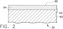
図2を参照すると、タービンエンジンロータ構成部品30の金属基体60は、様々な金属、或いはより典型的にはニッケル、コバルト及び/又は鉄合金をベースにしたものを含む金属合金のいずれかを含むことができる。基体60は一般的に、ニッケル、コバルト及び/又は鉄をベースにした超合金を含む。そのような超合金は、例えば、1990年9月18日に登録された同一出願人による米国特許第4,957,567号(Krueger他)、及び2003年2月18に登録された米国特許第6,521,175号(Mourer他)などの様々な参考文献に開示されており、これら特許の関連部分は参考文献として本明細書に組み入れている。超合金はまた、Kirk−Othmer’s Encyclopedia of Chemical Technology第3版12巻417−479ページ(1980年)及び15巻787−800ページ(1981年)に全体的に記載されている。実例的なニッケル基超合金は、商品名Inconel(登録商標)、Nimonic(登録商標)、Rene(登録商標)(例えば、Rene(登録商標)88、Rene(登録商標)104、ReneN5合金)及びUdimet(登録商標)によって指定される。
Referring to FIG. 2, the
基体60は、より典型的にはニッケル基合金、より具体的にはあらゆる他の元素よりも多いニッケルを有するニッケル基超合金を含む。ニッケル基超合金は、ガンマプライム又は関連相の析出によって強化することができる。本発明のセラミック耐食皮膜が特に有用であるニッケル基超合金は、商品名Rene88によって入手可能であり、それは、重量で13%のコバルト、16%のクロム、4%のモリブデン、3.7%のチタン、2.1%のアルミニウム、4%のタングステン、0.70%のニオブ、0.015%のホウ素、0.03%のジルコニウム及び0.03%の炭素と、残部のニッケル及び微量の不純物を含む公称組成を有する。
The
本発明のセラミック耐食皮膜64を金属基体60の表面62上に形成する際に、表面62は一般的に、機械的、化学的又はその両方で前処理してその表面が皮膜64をより受けやすくなるようにする。適当な前処理方法には、グリットブラストを受けない表面をマスキングした状態又はマスキングしない状態でのグリットブラスト(1998年3月3日に登録されたNiagara他の米国特許第5,723,078号の特に第4欄46−66行を参照されたく、この特許は、参考文献として本明細書に組み入れている)、ミクロ機械加工、レーザエッチング(1998年3月3日に登録されたNagaraj他の米国特許第5,723,078号の特に第4欄67行から第5欄3行まで及び第5欄14−17行を参照されたく、この特許は、参考文献として本明細書に組み入れている)、塩酸、フッ酸、硝酸、重フッ化アンモニウム及びそれらの混合物を含む化学エッチング液のような化学エッチング液を用いる処理(例えば、1998年3月3日に登録されたNagaraj他の米国特許第5,723,078号の特に第5欄3−10行、1986年1月7日に登録されたAdinolfi他の米国特許第4,563,239号の特に第2欄67行から第3欄7行まで、1982年10月12日に登録されたFishter他の米国特許第4,353,780号の特に第1欄50−58行、及び1983年10月25日に登録されたFishter他の米国特許第4,411,730号の特に第2欄40−51行を参照されたく、これら特許は全て参考文献として本明細書に組み入れている)、研磨粒子を加えた状態又は加えない状態での圧力下の水を用いる処理(すなわち、水噴射処理)、並びにそれら方法の様々な組合せが含まれる。一般的に、金属基体60の表面62は、該表面62が炭化ケイ素粒子、スチール粒子、アルミナ粒子又は他のタイプの研磨粒子の研磨作用を受けるようにグリッドブラストによって前処理される。グリッドブラストに用いるこれら粒子は一般的に、アルミナ粒子であり、典型的には約600〜約35メッシュ(約25〜約500マイクロメートル)、より典型的には約400〜約300メッシュ(約38〜約50マイクロメートル)の粒子サイズを有する。
In forming the ceramic corrosion
金属基体60上にセラミック耐食皮膜64を形成する本発明の方法の実施形態は、ソル・ゲル法の使用によるものである。2004年4月29日に公開された同一出願人による米国特許出願第2004/0081767号(Pfaendtner他)を参照されたく、この特許出願は参考文献として本明細書に組み入れている。ソル・ゲル法は、セラミック酸化物(例えば、ジルコニア)を生成する化学溶液法である。一般的にはアルコキシド前駆体又は金属塩を含む化学ゲル形成溶液は、セラミック金属酸化物前駆体材料及び何らかの安定化金属酸化物前駆体材料などと混合される。ゲル形成溶液を僅かにそれを乾燥させるように第1の予め選択した時間にわたって第1の予め選択した温度で加熱すると、ゲルが形成される。ゲルは次に、金属基体60の表面62を覆って塗布される。セラミック金属酸化物前駆体材料を適当に加えかつ適当に乾燥させることにより、表面62を覆って連続フィルムが形成される。ソル・ゲルは、あらゆる都合のよい方法によって基体60の表面62に塗布することができる。例えばソル・ゲルは、少なくとも1つの薄層、例えば単一の薄層、又はより典型的には薄膜を皮膜64の所望の厚さまで堆積させるような複数の薄層をスプレイすることによって塗布することができる。ゲルは次に、第2の予め選択した時間にわたって第1の上昇温度以上の第2の予め選択した上昇温度で焼成されて皮膜64を形成する。セラミック耐食皮膜64は、最大約5ミル(127ミクロン)まで、典型的には約0.01〜約1ミル(約0.2〜約25ミクロン)、より典型的には約0.04〜約0.5ミル(約1〜約13ミクロン)の厚さを有する緻密マトリックスを含む。任意選択的に、不活性酸化物充填粒子をソル・ゲル溶液に加えて、基体に施工される層ごとの厚さをより大きくことが可能になるようにすることができる。
An embodiment of the method of the present invention for forming a ceramic corrosion
セラミック耐食皮膜64を形成する別の方法は、電子ビームPVD(EB−PVD)、フィルタアーク蒸着などの物理気相蒸着(PVD)によるか、又はスパッタリングによるものである。本明細書で用いる適当なスパッタリング法には、それに限定されないが、直流ダイオードスパッタリング、高周波スパッタリング、イオンビームスパッタリング、反応性スパッタリング、マグネトロンスパッタリング及びステアードアークスパッタリングが含まれる。PVD法は、垂直マイクロクラック組織のような耐歪み性又は耐性ミクロ組織を有するセラミック耐食皮膜64を形成することができる。EB−PVD法は、高い耐歪み性があって皮膜密着性をさらに高める円柱状組織を形成することができる。これらの耐歪み性又は耐性組織は、皮膜表面66と基体60との間に直接経路を有するが、この経路は、部分溶融又は高粘性腐食性塩が、垂直マイクロクラック組織の割れ又は円柱状組織の円柱ギャップに全く侵入しない又は最小限度の侵入しかしないほど十分に狭い。
Another method of forming the ceramic corrosion
これらセラミック耐食皮膜を形成する別の適当な方法には、溶射、エアゾールスプレイ、化学気相蒸着(CVD)及びパックセメンテーションが含まれる。本明細書で用いる場合、「溶射」という用語は、被覆皮膜材料を加熱しかつ一般的にその被覆皮膜材料を少なくとも部分的に又は完全に熱溶融させるステップと一般的に加熱ガス流内の同伴によって加熱/溶融材料を被覆対象の金属基体上に被着させるステップとを含む、セラミック組成物を溶射し、施工し又は他の方法で被着させるあらゆる方法を意味する。適当な溶射被着法には、空気プラズマ溶射(APS)及び真空プラズマ溶射(VPS)などのプラズマ溶射、高速ガス式(HVOF)溶射、爆発溶射、線爆溶射など並びにそれらの方法の組合せが含まれる。本明細書で用いる場合の特に適当な溶射被着法は、プラズマ溶射である。適当なプラズマ溶射法は、当業者にはよく知られている。例えばKirk−Othmer Encyclopedia of Chemical Technology第3版15巻255ページ及びその中に記載された参考文献、並びに1994年7月26日に登録された米国特許第5,332,598号(Kawasaki他)、1991年9月10に登録された米国特許第5,047,612号(Savkar他)及び1998年5月3日に登録された米国特許第4,741,286号(Itoh他)(これらは参考文献として本明細書に組み入れている)を参照されたく、これらは本明細書で用いるのに適したプラズマ溶射の様々な態様に関して非常に役立つ。 Other suitable methods for forming these ceramic corrosion resistant coatings include thermal spraying, aerosol spraying, chemical vapor deposition (CVD) and pack cementation. As used herein, the term “spraying” refers to the steps of heating a coating material and generally at least partially or completely heat-melting the coating material and generally entraining in a heated gas stream. Means by which the ceramic composition is thermally sprayed, applied or otherwise applied, including the step of depositing the heated / molten material onto the metal substrate to be coated. Suitable thermal spray deposition methods include plasma spraying such as air plasma spraying (APS) and vacuum plasma spraying (VPS), high velocity gas (HVOF) spraying, explosion spraying, line explosion spraying and combinations of these methods. It is. A particularly suitable thermal spray deposition method for use herein is plasma spraying. Suitable plasma spraying methods are well known to those skilled in the art. For example, Kirk-Othmer Encyclopedia of Chemical Technology, 3rd edition, Volume 15, page 255 and references described therein, and US Pat. No. 5,332,598 (Kawasaki et al.) Registered on July 26, 1994, US Pat. No. 5,047,612 (Savkar et al.) Registered on September 10, 1991 and US Pat. No. 4,741,286 (Itoh et al.) Registered on May 3, 1998 (these are for reference only) (Incorporated herein by reference), which are very helpful with respect to various aspects of plasma spraying suitable for use herein.
化学気相蒸着及び/又はパックセメンテーションを実施する適当な方法は、例えば、1970年11月17日に登録された同一出願による米国特許第3,540,878号(Levine他)、1971年8月10日に登録された同一出願人による米国特許第3,598,638号(Levine)、及び1972年6月6日に登録された同一出願人による米国特許第3,667,985号(Levine他)に開示されており、これら特許の関連する開示内容は参考文献として本明細書に組み入れている。有機金属化学気相蒸着(MOCVD)法もまた本明細書で用いることができる。2004年1月22日に公開された同一出願による米国特許出願第2004/0013802号(Ackerman他)を参照されたく、この特許出願の関連する開示内容は参考文献として本明細書に組み入れている。 Suitable methods for performing chemical vapor deposition and / or pack cementation are described, for example, in US Pat. No. 3,540,878 (Levine et al.), 1971 8 by the same application registered on November 17, 1970. US Pat. No. 3,598,638 (Levine) filed on the 10th of the month and US Pat. No. 3,667,985 (Levine) filed on 6/6/1972. The relevant disclosures of these patents are incorporated herein by reference. Metalorganic chemical vapor deposition (MOCVD) methods can also be used herein. See commonly-assigned US Patent Application No. 2004/0013802 (Ackerman et al.) Published Jan. 22, 2004, the relevant disclosure of which is incorporated herein by reference.
図3に示すように、一般的に、これらタービンディスク/シャフト、シール及び/又はブレードリテーナの表面の一部分のみに、本発明のセラミック耐食皮膜64が設けられる。図3は、符号74で示したほぼ円形の内側ハブ部分及び符号78で示したほぼ円形の外周又は外径と、符号38、42などのタービンブレードの根元部分を受けるための符号86で示した複数の円周方向に間隙を置いて配置されたスロットを備えた符号82で示した周辺部とを有するタービンディスク32を示す。セラミック耐食皮膜64は、ディスク70の表面全体に施工することができるが、一般的には外径78の表面上にのみ必要とされる。
As shown in FIG. 3, in general, only a portion of the surface of the turbine disk / shaft, seal and / or blade retainer is provided with the ceramic corrosion
上記の実施形態は、タービンエンジンディスクを被覆することに関して説明してきたが、上述のように、本発明を用いて、圧縮機ディスク、シール及びシャフトを含む様々なタービンエンジンロータ構成部品の表面上にセラミック耐食皮膜64を形成することができ、構成部品は次に、高温で腐食性要素に露出させることができる。本発明のセラミック耐食皮膜はまた、構成部品の最初の製造(すなわち、OEM構成部品)の時に、構成部品をある期間作動させた後に、構成部品から他の皮膜を除去した後に(例えば、補修状況時)、構成部品を組み立てている間に、又は構成部品を分解した後などに施工することができる。
Although the above embodiments have been described with respect to coating turbine engine disks, as described above, the present invention can be used on the surface of various turbine engine rotor components including compressor disks, seals and shafts. A ceramic corrosion
以下の実施例は、本発明のセラミック耐食皮膜をソル・ゲル法によって金属基体上に形成する実施形態及びそれによって得られる利点を示す。 The following examples show embodiments of the ceramic corrosion resistant coating of the present invention formed on a metal substrate by the sol-gel method and the advantages obtained thereby.
ReneN5合金の1インチ円形試料は、ソル・ゲルにより被着させた7重量%のイットリア安定化ジルコニアの約5ミクロンの層で被覆されている。硫酸含有腐食性物質(腐食剤)を皮膜の表面に塗布し、1300°F(704℃)において2時間サイクルでテストを行う。2時間サイクルの最初の1時間は、還元性雰囲気を用いて腐食剤と被覆試料の表面との間に反応を引き起こさせることを試みる一方、次の1時間は、空気を用いて腐食スケール成長を引き起こさせる。水洗浄によって腐食剤を除去し、次に被覆試料は損傷を検査される。この腐食剤塗布、熱露出、洗浄及び検査のサイクルは、被覆試料が損傷の兆候を示すまで反復される。8サイクル後に、被覆試料上には明らかな損傷は全く見られない。10サイクル後に、皮膜は依然として合金に密着しているが、変色が見られ、被覆試料は評価のため切断される。切断後に、皮膜の下には約10ミクロン厚さの腐食生成層が見られる。ちなみに、これは、裸の合金試料(すなわち、皮膜してない)のこのようなテストの約2サイクル後の典型的な状態である。 A 1 inch circular sample of ReneN5 alloy is coated with an approximately 5 micron layer of 7 wt% yttria stabilized zirconia deposited by Sol Gel. A sulfuric acid-containing corrosive substance (corrosive) is applied to the surface of the film and tested at 1300 ° F. (704 ° C.) with a two hour cycle. The first hour of the 2 hour cycle attempts to cause a reaction between the corrosive agent and the surface of the coated sample using a reducing atmosphere, while the next hour uses air to cause corrosion scale growth. Cause. The corrosive agent is removed by water washing, and the coated sample is then inspected for damage. This cycle of caustic application, heat exposure, cleaning and inspection is repeated until the coated sample shows signs of damage. After 8 cycles, no obvious damage is seen on the coated sample. After 10 cycles, the coating is still in close contact with the alloy, but discoloration is seen and the coated sample is cut for evaluation. After cutting, a corrosion-generating layer about 10 microns thick is seen under the coating. Incidentally, this is a typical condition after about two cycles of such a test on a bare alloy sample (ie, uncoated).
本発明の特定の実施形態を説明してきたが、特許請求の範囲に記載した本発明の技術思想及び技術的範囲から逸脱することなく、実施形態に対する様々な変更を加えることができることは当業者には明らかであろう。 While specific embodiments of the present invention have been described, it will be apparent to those skilled in the art that various modifications can be made to the embodiments without departing from the spirit and scope of the invention as set forth in the claims. Will be clear.
30 タービンエンジンロータ構成部品
32 タービンディスク
34 タービンシール要素
36 第1段タービンディスク
38 第1段タービンブレード
40 第2段タービンディスク
42 第2段タービンブレード
44 前部タービンシール
46 後部タービンシール
48 段間タービンシール
52 ブレードリテーナ
60 基体
62 基体60の表面
64 セラミック耐食皮膜
66 皮膜64の表面
74 ディスク32の内側ハブ
78 ディスク32の外周又は外径
82 ディスク32の周辺部
86 ブレード38、42の根元を受けるための複数のスロット
30 Turbine
38 First
Claims (8)
前記セラミック耐食皮膜(64)が0.2〜13ミクロンの厚さを有し、かつジルコニア、ハフニア及びそれらの混合物からなる群から選択されるセラミック金属酸化物60〜98モル%と、イットリア、カルシア、スカンジア、マグネシア、インジア、ガドリニア、ネオジミア、サマリア、ジスプロシア、エルビア、イッテルビア、ユウロピア、プラセオジミア、ランタナ、タンタラ及びそれらの混合物からなる群から選択される安定化金属酸化物2〜40モル%とからなる、物品。 Single layer ceramic corrosion resistant coating provided directly on the surface (62) of a turbine airfoil (38, 42) other than the turbine component (30) to the metal substrate (60) and said metal substrate (60) (64) An article comprising a turbine component (30) having
60 to 98 mol% of a ceramic metal oxide selected from the group consisting of zirconia, hafnia and a mixture thereof, wherein the ceramic corrosion resistant coating (64) has a thickness of 0.2 to 13 microns, yttria, calcia A stabilized metal oxide selected from the group consisting of: scandia, magnesia, india, gadolinia, neodymia, samaria, dysprosia, elvia, ytterbia, europia, praseodymia, lantana, tantala, and mixtures thereof. , Goods.
(b)セラミック金属酸化物前駆体を含むゲル形成溶液を準備するステップと、
(c)前記ゲル形成溶液を第1の予め選択した時間にわたって第1の予め選択した温度に加熱してゲルを形成するステップと、
(d)前記ゲルを前記金属基体(60)の表面(62)上に直接被着させるステップと、
(e)前記被着したゲルを前記第1の予め選択した温度よりも高い第2の予め選択した温度で焼成して、ジルコニア、ハフニア及びそれらの混合物からなる群から選択されるセラミック金属酸化物60〜98モル%と、イットリア、カルシア、スカンジア、マグネシア、インジア、ガドリニア、ネオジミア、サマリア、ジスプロシア、エルビア、イッテルビア、ユウロピア、プラセオジミア、ランタナ、タンタラ及びそれらの混合物からなる群から選択される安定化金属酸化物2〜40モル%とからなる厚さ0.2〜13ミクロンの単一層セラミック耐食皮膜(64)を形成するステップと、
を具備するタービン構成部品の製造方法。 (A) providing a turbine component (30) comprising a metal substrate (60), other than a turbine airfoil (38, 42);
(B) providing a gel-forming solution comprising a ceramic metal oxide precursor;
(C) heating the gel-forming solution to a first preselected temperature for a first preselected time to form a gel;
(D) depositing the gel directly on the surface (62) of the metal substrate (60);
(E) a ceramic metal oxide selected from the group consisting of zirconia, hafnia and mixtures thereof by firing the deposited gel at a second preselected temperature higher than the first preselected temperature. 60 to 98 mol% and a stabilizing metal selected from the group consisting of yttria, calcia, scandia, magnesia, india, gadolinia, neodymia, samaria, dysprosia, elvia, ytterbia, europia, praseodymia, lantana, tantala and mixtures thereof Forming a 0.2 to 13 micron thick single layer ceramic corrosion resistant coating (64) comprising 2 to 40 mole percent oxide;
A method for manufacturing a turbine component comprising:
Applications Claiming Priority (2)
| Application Number | Priority Date | Filing Date | Title |
|---|---|---|---|
| US11/094,351 | 2005-03-31 | ||
| US11/094,351 US7666515B2 (en) | 2005-03-31 | 2005-03-31 | Turbine component other than airfoil having ceramic corrosion resistant coating and methods for making same |
Publications (3)
| Publication Number | Publication Date |
|---|---|
| JP2006283759A JP2006283759A (en) | 2006-10-19 |
| JP2006283759A5 JP2006283759A5 (en) | 2009-04-30 |
| JP5225551B2 true JP5225551B2 (en) | 2013-07-03 |
Family
ID=36570571
Family Applications (1)
| Application Number | Title | Priority Date | Filing Date |
|---|---|---|---|
| JP2006093435A Expired - Fee Related JP5225551B2 (en) | 2005-03-31 | 2006-03-30 | Turbine component and manufacturing method thereof |
Country Status (3)
| Country | Link |
|---|---|
| US (3) | US7666515B2 (en) |
| EP (1) | EP1710398A1 (en) |
| JP (1) | JP5225551B2 (en) |
Families Citing this family (23)
| Publication number | Priority date | Publication date | Assignee | Title |
|---|---|---|---|---|
| US20090239061A1 (en) * | 2006-11-08 | 2009-09-24 | General Electric Corporation | Ceramic corrosion resistant coating for oxidation resistance |
| US9644273B2 (en) * | 2007-02-09 | 2017-05-09 | Honeywell International Inc. | Protective barrier coatings |
| EP2143884A1 (en) * | 2008-07-11 | 2010-01-13 | Siemens Aktiengesellschaft | Rotor disc for a turbomachine |
| JP5610698B2 (en) * | 2009-03-26 | 2014-10-22 | 三菱重工業株式会社 | Thermal barrier coating material, thermal barrier coating, turbine component and gas turbine |
| EP2233600B1 (en) | 2009-03-26 | 2020-04-29 | Ansaldo Energia Switzerland AG | Method for the protection of a thermal barrier coating system and a method for the renewal of such a protection |
| EP2416037B1 (en) * | 2009-03-30 | 2013-09-04 | Eagle Industry Co., Ltd. | Bellows type mechanical seal |
| US9568108B2 (en) * | 2009-03-30 | 2017-02-14 | Eagle Industry Co., Ltd. | Bellows type mechanical seal |
| GB0907278D0 (en) * | 2009-04-29 | 2009-06-10 | Rolls Royce Plc | A seal arrangement and a method of repairing a seal arrangement |
| CA2715958A1 (en) * | 2009-10-12 | 2011-04-12 | General Electric Company | Process of forming a coating system, coating system formed thereby, and components coated therewith |
| US20110280716A1 (en) * | 2010-05-17 | 2011-11-17 | Douglas Gerard Konitzer | Gas turbine engine compressor components comprising thermal barriers, thermal barrier systems, and methods of using the same |
| JP5815837B2 (en) | 2011-04-13 | 2015-11-17 | ロールス−ロイス コーポレイション | Interfacial diffusion barrier layer containing iridium on metal substrate |
| WO2014027162A1 (en) * | 2012-08-14 | 2014-02-20 | Snecma | Method for measuring the temperature reached by a part, in particular of a turbomachine |
| US20140094356A1 (en) * | 2012-09-28 | 2014-04-03 | General Electric Company | Treatment process, oxide-forming treatment composition, and treated component |
| US9764989B2 (en) | 2013-03-13 | 2017-09-19 | Rolls-Royce Corporation | Reactive fiber interface coatings for improved environmental stability |
| BR112015022549A2 (en) | 2013-03-13 | 2017-07-18 | Gen Electric | turbine and gas turbine component |
| EP2918705B1 (en) | 2014-03-12 | 2017-05-03 | Rolls-Royce Corporation | Coating including diffusion barrier layer including iridium and oxide layer and method of coating |
| US10280770B2 (en) | 2014-10-09 | 2019-05-07 | Rolls-Royce Corporation | Coating system including oxide nanoparticles in oxide matrix |
| US10047614B2 (en) | 2014-10-09 | 2018-08-14 | Rolls-Royce Corporation | Coating system including alternating layers of amorphous silica and amorphous silicon nitride |
| US11085116B2 (en) * | 2017-03-22 | 2021-08-10 | The Boeing Company | Engine shaft assembly and method |
| US11162457B2 (en) * | 2017-08-11 | 2021-11-02 | General Electric Company | Turbine fan system and method |
| US11555241B2 (en) * | 2018-07-03 | 2023-01-17 | Raytheon Technologies Corporation | Coating system having synthetic oxide layers |
| FR3111157B1 (en) * | 2020-06-05 | 2022-07-22 | Safran Aircraft Engines | Motor comprising a sealing member between two rotor elements |
| US12012870B1 (en) * | 2022-11-29 | 2024-06-18 | Rtx Corporation | Machinable coating for CMC and metal interface in a turbine section |
Family Cites Families (48)
| Publication number | Priority date | Publication date | Assignee | Title |
|---|---|---|---|---|
| US3248251A (en) * | 1963-06-28 | 1966-04-26 | Teleflex Inc | Inorganic coating and bonding composition |
| US3248250A (en) * | 1963-06-28 | 1966-04-26 | Teleflex Inc | Coating and bonding composition |
| US3248249A (en) * | 1963-06-28 | 1966-04-26 | Telefiex Inc | Inorganic coating and bonding composition |
| US3540878A (en) * | 1967-12-14 | 1970-11-17 | Gen Electric | Metallic surface treatment material |
| US3667985A (en) * | 1967-12-14 | 1972-06-06 | Gen Electric | Metallic surface treatment method |
| US3598638A (en) * | 1968-11-29 | 1971-08-10 | Gen Electric | Diffusion metallic coating method |
| US4411730A (en) * | 1980-10-01 | 1983-10-25 | United Technologies Corporation | Selective chemical milling of recast surfaces |
| US4353780A (en) * | 1980-10-01 | 1982-10-12 | United Technologies Corporation | Chemical milling of high tungsten content superalloys |
| US4563239A (en) * | 1984-10-16 | 1986-01-07 | United Technologies Corporation | Chemical milling using an inert particulate and moving vessel |
| JPS61259777A (en) * | 1985-05-13 | 1986-11-18 | Onoda Cement Co Ltd | Single-torch type plasma spraying method and apparatus |
| US4946710A (en) * | 1987-06-02 | 1990-08-07 | National Semiconductor Corporation | Method for preparing PLZT, PZT and PLT sol-gels and fabricating ferroelectric thin films |
| US5015502A (en) * | 1988-11-03 | 1991-05-14 | Allied-Signal Inc. | Ceramic thermal barrier coating with alumina interlayer |
| US4957567A (en) * | 1988-12-13 | 1990-09-18 | General Electric Company | Fatigue crack growth resistant nickel-base article and alloy and method for making |
| US5221354A (en) * | 1991-11-04 | 1993-06-22 | General Electric Company | Apparatus and method for gas phase coating of hollow articles |
| JPH0693404A (en) * | 1991-12-04 | 1994-04-05 | Ngk Insulators Ltd | Production of lanthanum chromite film and lanthanum chromite coating |
| DE4417405A1 (en) * | 1994-05-18 | 1995-11-23 | Inst Neue Mat Gemein Gmbh | Process for the production of structured inorganic layers |
| US5660885A (en) * | 1995-04-03 | 1997-08-26 | General Electric Company | Protection of thermal barrier coating by a sacrificial surface coating |
| US5824423A (en) * | 1996-02-07 | 1998-10-20 | N.V. Interturbine | Thermal barrier coating system and methods |
| US5723078A (en) | 1996-05-24 | 1998-03-03 | General Electric Company | Method for repairing a thermal barrier coating |
| US5753078A (en) * | 1996-06-07 | 1998-05-19 | Cartons St-Laurent, Inc./St. Laurent Paperboard, Inc. | Method of making surface coated or impregnated paper or paperboard |
| US6924040B2 (en) * | 1996-12-12 | 2005-08-02 | United Technologies Corporation | Thermal barrier coating systems and materials |
| JPH10195629A (en) * | 1996-12-27 | 1998-07-28 | Mitsubishi Heavy Ind Ltd | Gas turbine blade and method for forming film thereon |
| US6057047A (en) * | 1997-11-18 | 2000-05-02 | United Technologies Corporation | Ceramic coatings containing layered porosity |
| US6521175B1 (en) * | 1998-02-09 | 2003-02-18 | General Electric Co. | Superalloy optimized for high-temperature performance in high-pressure turbine disks |
| US6641907B1 (en) * | 1999-12-20 | 2003-11-04 | Siemens Westinghouse Power Corporation | High temperature erosion resistant coating and material containing compacted hollow geometric shapes |
| US6106959A (en) * | 1998-08-11 | 2000-08-22 | Siemens Westinghouse Power Corporation | Multilayer thermal barrier coating systems |
| US6146692A (en) * | 1998-12-14 | 2000-11-14 | General Electric Company | Caustic process for replacing a thermal barrier coating |
| US6296447B1 (en) * | 1999-08-11 | 2001-10-02 | General Electric Company | Gas turbine component having location-dependent protective coatings thereon |
| US6224673B1 (en) * | 1999-08-11 | 2001-05-01 | General Electric Company | Apparatus for masking turbine components during vapor phase diffusion coating |
| US6270318B1 (en) * | 1999-12-20 | 2001-08-07 | United Technologies Corporation | Article having corrosion resistant coating |
| JP2003075326A (en) * | 2001-08-31 | 2003-03-12 | Mitsubishi Heavy Ind Ltd | Evaluation method and evaluation device for heat insulating coating film |
| US6821641B2 (en) * | 2001-10-22 | 2004-11-23 | General Electric Company | Article protected by thermal barrier coating having a sintering inhibitor, and its fabrication |
| US20030118873A1 (en) * | 2001-12-21 | 2003-06-26 | Murphy Kenneth S. | Stabilized zirconia thermal barrier coating with hafnia |
| US6682821B2 (en) * | 2001-12-28 | 2004-01-27 | Kyocera Corporation | Corrosion-resistant ceramics |
| US20030138658A1 (en) * | 2002-01-22 | 2003-07-24 | Taylor Thomas Alan | Multilayer thermal barrier coating |
| US20030152814A1 (en) * | 2002-02-11 | 2003-08-14 | Dinesh Gupta | Hybrid thermal barrier coating and method of making the same |
| US6616978B1 (en) * | 2002-05-09 | 2003-09-09 | General Electric Company | Protecting a substrate with a multilayer oxide/phosphate coating having a temperature-stepped cure |
| US6746783B2 (en) * | 2002-06-27 | 2004-06-08 | General Electric Company | High-temperature articles and method for making |
| US6926928B2 (en) * | 2002-07-19 | 2005-08-09 | General Electric Company | Protection of a gas turbine component by a vapor-deposited oxide coating |
| US6884476B2 (en) * | 2002-10-28 | 2005-04-26 | General Electric Company | Ceramic masking material and application method for protecting turbine airfoil component surfaces during vapor phase aluminiding |
| US6933061B2 (en) * | 2002-12-12 | 2005-08-23 | General Electric Company | Thermal barrier coating protected by thermally glazed layer and method for preparing same |
| US20040115470A1 (en) * | 2002-12-12 | 2004-06-17 | Ackerman John Frederick | Thermal barrier coating protected by infiltrated alumina and method for preparing same |
| US6893750B2 (en) * | 2002-12-12 | 2005-05-17 | General Electric Company | Thermal barrier coating protected by alumina and method for preparing same |
| US6905730B2 (en) * | 2003-07-08 | 2005-06-14 | General Electric Company | Aluminide coating of turbine engine component |
| US7455890B2 (en) | 2003-08-05 | 2008-11-25 | General Electric Company | Ion implantation of turbine engine rotor component |
| US6887595B1 (en) * | 2003-12-30 | 2005-05-03 | General Electric Company | Thermal barrier coatings having lower layer for improved adherence to bond coat |
| US6869703B1 (en) * | 2003-12-30 | 2005-03-22 | General Electric Company | Thermal barrier coatings with improved impact and erosion resistance |
| US7654645B2 (en) * | 2005-04-04 | 2010-02-02 | Silverbrook Research Pty Ltd | MEMS bubble generator |
-
2005
- 2005-03-31 US US11/094,351 patent/US7666515B2/en active Active
-
2006
- 2006-03-23 EP EP06251560A patent/EP1710398A1/en not_active Ceased
- 2006-03-30 JP JP2006093435A patent/JP5225551B2/en not_active Expired - Fee Related
-
2009
- 2009-04-09 US US12/421,149 patent/US20090191347A1/en not_active Abandoned
- 2009-04-09 US US12/421,190 patent/US20090191353A1/en not_active Abandoned
Also Published As
| Publication number | Publication date |
|---|---|
| US20090191353A1 (en) | 2009-07-30 |
| EP1710398A1 (en) | 2006-10-11 |
| US7666515B2 (en) | 2010-02-23 |
| JP2006283759A (en) | 2006-10-19 |
| US20090191347A1 (en) | 2009-07-30 |
| US20060222884A1 (en) | 2006-10-05 |
Similar Documents
| Publication | Publication Date | Title |
|---|---|---|
| JP5225551B2 (en) | Turbine component and manufacturing method thereof | |
| JP5160194B2 (en) | Ceramic corrosion resistant coating for oxidation resistance | |
| JP4191427B2 (en) | Improved plasma sprayed thermal bond coat system | |
| EP1595977B1 (en) | Superalloy article having corrosion resistant coating thereon | |
| US6365281B1 (en) | Thermal barrier coatings for turbine components | |
| US7604867B2 (en) | Particulate corrosion resistant coating composition, coated turbine component and method for coating same | |
| JP3258599B2 (en) | Insulation barrier coating system | |
| US20100126014A1 (en) | Repair method for tbc coated turbine components | |
| EP1752559A2 (en) | Method for restoring portion of turbine component | |
| EP1627862A1 (en) | Ceramic compositions for thermal barrier coatings with improved mechanical properties | |
| JP2005199419A (en) | Method for mending parts using environment-resistant bond membrane, and resulting mended parts | |
| JP2010043351A (en) | Thermal barrier coating and method for production thereof | |
| US20090123722A1 (en) | Coating system | |
| JP3579262B2 (en) | Bonding coat for thermal barrier coating system | |
| US20100279148A1 (en) | Nickel-based alloys and turbine components | |
| US20040247789A1 (en) | Method of globally repairing a part covered with a thermal barrier | |
| US20110293963A1 (en) | Coatings, turbine engine components, and methods for coating turbine engine components | |
| EP3012343B1 (en) | Coating system for internally-cooled component and process therefor | |
| Stolle | Conventional and advanced coatings for turbine airfoils | |
| EP2423347A1 (en) | Method for forming a thermal barrier coating and a turbine component with the thermal barrier coating | |
| US11274562B2 (en) | Gas turbine components and methods of assembling the same |
Legal Events
| Date | Code | Title | Description |
|---|---|---|---|
| A521 | Request for written amendment filed |
Free format text: JAPANESE INTERMEDIATE CODE: A523 Effective date: 20090312 |
|
| A621 | Written request for application examination |
Free format text: JAPANESE INTERMEDIATE CODE: A621 Effective date: 20090312 |
|
| RD02 | Notification of acceptance of power of attorney |
Free format text: JAPANESE INTERMEDIATE CODE: A7422 Effective date: 20090313 |
|
| RD04 | Notification of resignation of power of attorney |
Free format text: JAPANESE INTERMEDIATE CODE: A7424 Effective date: 20090313 |
|
| A131 | Notification of reasons for refusal |
Free format text: JAPANESE INTERMEDIATE CODE: A131 Effective date: 20101214 |
|
| A601 | Written request for extension of time |
Free format text: JAPANESE INTERMEDIATE CODE: A601 Effective date: 20110314 |
|
| A602 | Written permission of extension of time |
Free format text: JAPANESE INTERMEDIATE CODE: A602 Effective date: 20110317 |
|
| A521 | Request for written amendment filed |
Free format text: JAPANESE INTERMEDIATE CODE: A523 Effective date: 20110610 |
|
| A131 | Notification of reasons for refusal |
Free format text: JAPANESE INTERMEDIATE CODE: A131 Effective date: 20110712 |
|
| A601 | Written request for extension of time |
Free format text: JAPANESE INTERMEDIATE CODE: A601 Effective date: 20111011 |
|
| A602 | Written permission of extension of time |
Free format text: JAPANESE INTERMEDIATE CODE: A602 Effective date: 20111014 |
|
| A131 | Notification of reasons for refusal |
Free format text: JAPANESE INTERMEDIATE CODE: A131 Effective date: 20120313 |
|
| A601 | Written request for extension of time |
Free format text: JAPANESE INTERMEDIATE CODE: A601 Effective date: 20120613 |
|
| A602 | Written permission of extension of time |
Free format text: JAPANESE INTERMEDIATE CODE: A602 Effective date: 20120618 |
|
| TRDD | Decision of grant or rejection written | ||
| A01 | Written decision to grant a patent or to grant a registration (utility model) |
Free format text: JAPANESE INTERMEDIATE CODE: A01 Effective date: 20130212 |
|
| A61 | First payment of annual fees (during grant procedure) |
Free format text: JAPANESE INTERMEDIATE CODE: A61 Effective date: 20130313 |
|
| R150 | Certificate of patent or registration of utility model |
Ref document number: 5225551 Country of ref document: JP Free format text: JAPANESE INTERMEDIATE CODE: R150 Free format text: JAPANESE INTERMEDIATE CODE: R150 |
|
| FPAY | Renewal fee payment (event date is renewal date of database) |
Free format text: PAYMENT UNTIL: 20160322 Year of fee payment: 3 |
|
| R250 | Receipt of annual fees |
Free format text: JAPANESE INTERMEDIATE CODE: R250 |
|
| R250 | Receipt of annual fees |
Free format text: JAPANESE INTERMEDIATE CODE: R250 |
|
| R250 | Receipt of annual fees |
Free format text: JAPANESE INTERMEDIATE CODE: R250 |
|
| R250 | Receipt of annual fees |
Free format text: JAPANESE INTERMEDIATE CODE: R250 |
|
| R250 | Receipt of annual fees |
Free format text: JAPANESE INTERMEDIATE CODE: R250 |
|
| R250 | Receipt of annual fees |
Free format text: JAPANESE INTERMEDIATE CODE: R250 |
|
| R250 | Receipt of annual fees |
Free format text: JAPANESE INTERMEDIATE CODE: R250 |
|
| LAPS | Cancellation because of no payment of annual fees |