JP5225242B2 - Target positioning method and target positioning system with adaptive resolution - Google Patents
Target positioning method and target positioning system with adaptive resolution Download PDFInfo
- Publication number
- JP5225242B2 JP5225242B2 JP2009220184A JP2009220184A JP5225242B2 JP 5225242 B2 JP5225242 B2 JP 5225242B2 JP 2009220184 A JP2009220184 A JP 2009220184A JP 2009220184 A JP2009220184 A JP 2009220184A JP 5225242 B2 JP5225242 B2 JP 5225242B2
- Authority
- JP
- Japan
- Prior art keywords
- resolution
- position signal
- positioning
- low
- resolution position
- Prior art date
- Legal status (The legal status is an assumption and is not a legal conclusion. Google has not performed a legal analysis and makes no representation as to the accuracy of the status listed.)
- Expired - Fee Related
Links
Images


Classifications
-
- G—PHYSICS
- G01—MEASURING; TESTING
- G01S—RADIO DIRECTION-FINDING; RADIO NAVIGATION; DETERMINING DISTANCE OR VELOCITY BY USE OF RADIO WAVES; LOCATING OR PRESENCE-DETECTING BY USE OF THE REFLECTION OR RERADIATION OF RADIO WAVES; ANALOGOUS ARRANGEMENTS USING OTHER WAVES
- G01S5/00—Position-fixing by co-ordinating two or more direction or position line determinations; Position-fixing by co-ordinating two or more distance determinations
- G01S5/18—Position-fixing by co-ordinating two or more direction or position line determinations; Position-fixing by co-ordinating two or more distance determinations using ultrasonic, sonic, or infrasonic waves
-
- G—PHYSICS
- G01—MEASURING; TESTING
- G01S—RADIO DIRECTION-FINDING; RADIO NAVIGATION; DETERMINING DISTANCE OR VELOCITY BY USE OF RADIO WAVES; LOCATING OR PRESENCE-DETECTING BY USE OF THE REFLECTION OR RERADIATION OF RADIO WAVES; ANALOGOUS ARRANGEMENTS USING OTHER WAVES
- G01S5/00—Position-fixing by co-ordinating two or more direction or position line determinations; Position-fixing by co-ordinating two or more distance determinations
- G01S5/02—Position-fixing by co-ordinating two or more direction or position line determinations; Position-fixing by co-ordinating two or more distance determinations using radio waves
- G01S5/0252—Radio frequency fingerprinting
- G01S5/02521—Radio frequency fingerprinting using a radio-map
- G01S5/02524—Creating or updating the radio-map
- G01S5/02525—Gathering the radio frequency fingerprints
-
- G—PHYSICS
- G01—MEASURING; TESTING
- G01S—RADIO DIRECTION-FINDING; RADIO NAVIGATION; DETERMINING DISTANCE OR VELOCITY BY USE OF RADIO WAVES; LOCATING OR PRESENCE-DETECTING BY USE OF THE REFLECTION OR RERADIATION OF RADIO WAVES; ANALOGOUS ARRANGEMENTS USING OTHER WAVES
- G01S5/00—Position-fixing by co-ordinating two or more direction or position line determinations; Position-fixing by co-ordinating two or more distance determinations
- G01S5/02—Position-fixing by co-ordinating two or more direction or position line determinations; Position-fixing by co-ordinating two or more distance determinations using radio waves
- G01S5/0252—Radio frequency fingerprinting
- G01S5/02521—Radio frequency fingerprinting using a radio-map
- G01S5/02524—Creating or updating the radio-map
- G01S5/02527—Detecting or resolving anomalies in the radio frequency fingerprints of the radio-map
-
- G—PHYSICS
- G01—MEASURING; TESTING
- G01S—RADIO DIRECTION-FINDING; RADIO NAVIGATION; DETERMINING DISTANCE OR VELOCITY BY USE OF RADIO WAVES; LOCATING OR PRESENCE-DETECTING BY USE OF THE REFLECTION OR RERADIATION OF RADIO WAVES; ANALOGOUS ARRANGEMENTS USING OTHER WAVES
- G01S5/00—Position-fixing by co-ordinating two or more direction or position line determinations; Position-fixing by co-ordinating two or more distance determinations
- G01S5/02—Position-fixing by co-ordinating two or more direction or position line determinations; Position-fixing by co-ordinating two or more distance determinations using radio waves
- G01S5/0257—Hybrid positioning
- G01S5/0263—Hybrid positioning by combining or switching between positions derived from two or more separate positioning systems
- G01S5/0264—Hybrid positioning by combining or switching between positions derived from two or more separate positioning systems at least one of the systems being a non-radio wave positioning system
-
- G—PHYSICS
- G01—MEASURING; TESTING
- G01S—RADIO DIRECTION-FINDING; RADIO NAVIGATION; DETERMINING DISTANCE OR VELOCITY BY USE OF RADIO WAVES; LOCATING OR PRESENCE-DETECTING BY USE OF THE REFLECTION OR RERADIATION OF RADIO WAVES; ANALOGOUS ARRANGEMENTS USING OTHER WAVES
- G01S5/00—Position-fixing by co-ordinating two or more direction or position line determinations; Position-fixing by co-ordinating two or more distance determinations
- G01S5/02—Position-fixing by co-ordinating two or more direction or position line determinations; Position-fixing by co-ordinating two or more distance determinations using radio waves
- G01S5/14—Determining absolute distances from a plurality of spaced points of known location
Description
本発明は、 本発明は、測位システムと位置検出に関し、特に、本発明は、高精度の測位技術(例えば、超音波(US)測位)と低い精度の測位技術(位置情報サービスのための適応性のある測位分解能を提供する無線周波数(RF)測位)を組み合わせたハイブリッド測位方法およびシステムに関する。
The present invention relates to a positioning system and position detection. In particular, the present invention relates to a high-precision positioning technique (for example, ultrasonic (US) positioning) and a low-precision positioning technique (adaptation for position information service). The present invention relates to a hybrid positioning method and system in combination with radio frequency (RF) positioning that provides reliable positioning resolution.
疑いなく、位置情報は、利用者の行動をより理解するために利用者と環境の地理的な関係を抽出するのに利用される基本的なコンテンツである。位置認識(Location-aware)アプリケーションの重要性および将来性は、特に屋内や都市の環境における位置情報を提供するシステムの設計および実施に結びつく。現在、オフィス、ヘルスケア、炭鉱、地下鉄道、スマートビルディング、レストランなどを含む様々な適用シナリオ(application scenarios)において、リアルタイムに人々と資産の高精度トラッキングに対する市場のニーズが増加している。例えば、オフィス環境において、従業員は、一定の安全な区域で秘密情報データベースにアクセスすることを要求される。区域の外では、どのようなアクセスも禁止される。安全な区域の例としては、シングルルーム、作業領域の一部およびテーブルなどが考えられる。 Without doubt, location information is the basic content used to extract the geographical relationship between the user and the environment in order to better understand the user's behavior. The importance and future of location-aware applications lead to the design and implementation of systems that provide location information, especially in indoor and urban environments. Currently, there is an increasing market need for high-precision tracking of people and assets in real time in a variety of application scenarios including offices, healthcare, coal mines, subways, smart buildings, restaurants, etc. For example, in an office environment, employees are required to access a confidential information database in a certain secure area. Any access outside the area is prohibited. Examples of safe areas include a single room, part of a work area, and a table.
これまで、多くの測位システムが位置情報サービスを提供するために開発されている。しかしながら、既存の測位システムにはいくつかの共通する性能的制限がある。 To date, many positioning systems have been developed to provide location information services. However, existing positioning systems have some common performance limitations.
まず、技術的観点から、ほとんどの測位システムは、単一タイプの測位装置(超音波ベースあるいはRFベースの対象測位のための装置)の利用に焦点を置いている。実際、それぞれの信号タイプは利点を有しているがいくつかの欠点も有している。例えば、超音波に基づく位置測定ついては、高精度を実現できるが有効範囲が狭い。また、一方、RFに基づく手法については、有効範囲は広いが精度が低い。 First, from a technical point of view, most positioning systems focus on the use of a single type of positioning device (device for ultrasound-based or RF-based target positioning). In fact, each signal type has advantages but also some drawbacks. For example, with respect to position measurement based on ultrasonic waves, high accuracy can be realized, but the effective range is narrow. On the other hand, the method based on RF has a wide effective range but low accuracy.
次に、適用観点(例えば、ロケーションベースのアクセス・コントロール)から、通常人々は異なるエリア毎に異なる測位分解能を必要とするということである。関心のあるエリアでは、そのエリアの測位結果が非常に正確であることを確信するために高い測位粒度が必要である。その他のエリアでは、粗い測位粒度が許容される可能性がある。 Second, from an application perspective (eg, location-based access control), people usually require different positioning resolutions in different areas. In an area of interest, a high positioning granularity is required to be confident that the positioning results in that area are very accurate. In other areas, coarse positioning granularity may be acceptable.
以下に、屋内の測位のための既存の一般的な技術の簡単な概要を説明する。ここで注目すべき最も重要な点は、グローバル・ポジショニング・システム(GPS)は、数10メートルの精度で屋外における対象の位置情報を提供することができることである。しかし、室内環境においては、GPSのポジショニング結果がマルチパスの影響および信号の障害物によって著しく低くなるのでGPSはうまく機能しない。 In the following, a brief overview of existing general techniques for indoor positioning is described. The most important point to note here is that the Global Positioning System (GPS) can provide location information for objects outdoors with an accuracy of tens of meters. However, in indoor environments, GPS does not work well because GPS positioning results are significantly reduced by multipath effects and signal obstructions.
一般に、屋内の測位システムには、一般に3つの技術が用いられている。すなわち、超音波(US)測位、無線周波数(RF)測位および赤外線測位である。 Generally, three techniques are generally used for an indoor positioning system. That is, ultrasonic (US) positioning, radio frequency (RF) positioning, and infrared positioning.
例えば、「対象の位置と他の情報を判定するための検出システム」というタイトルの米国特許6,493,649号(特許文献1)のBatシステムにおいては、利用者は、集中システムによる無線が引き金となって超音波パルスを発する小さなバッジを身につける。
このBatシステムの概要が、例えば、図1Aに示されている。検出空間の天井には、多くの超音波受信機が密に設置されている。
このシステムは、バッジから天井に設置された多数の受信器配列までのパルスTOA(到着時間)を判定し、多辺測量アルゴリズムに基づいてバッジの3D位置を計算する。
For example, in the Bat system of US Pat. No. 6,493,649 (Patent Document 1) titled “Detection System for Determining Target Location and Other Information”, the user is triggered by radio from the centralized system. And wear a small badge that emits an ultrasonic pulse.
An overview of this Bat system is shown, for example, in FIG. 1A. Many ultrasonic receivers are densely installed on the ceiling of the detection space.
This system determines the pulse TOA (arrival time) from the badge to multiple receiver arrays installed on the ceiling and calculates the 3D position of the badge based on a multi-sided survey algorithm.
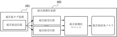
Batシステムと同様の超音波測位システムの構成ブロック図を、図1Bに示す。超音波タグ装置101は、超音波送信器を含んでおり、位置を特定する対象に付けられる。天井に設置された超音波測位装置102は複数の超音波受信機を含んでいる。超音波測位装置102の超音波測位ユニットは、異なる送信器から3つ以上のTOA結果を受け取り、次に多辺測量あるいは三角測量方法を用いることにより対象の位置を推測することができる。対象の計算された位置は、超音波結果メモリーに記憶される。
FIG. 1B shows a configuration block diagram of an ultrasonic positioning system similar to the Bat system. The
他の非特許文献1「RADAR:An In-Building RF-based User Location and
Tracking System(RFベースの利用者測位と追尾システムの構築)、P.Bahl.etc.、Proc.IEEE INFOCOM、2000”においては、802.11の無線ネットワークにおいて受信した信号の強さに基づいた測位システムが提示されている。
基本的なRADAR測位方法は、2つの工程で実行される。まず、オフラインの工程において、システムが正確に調整され、また、ターゲット・エリアに分布された位置での受信信号の強度を有するモデルが作成される。次に、ターゲット・エリアにおけるオンライン処理中に、移動ユニットは、信号強度を各基地局から受信したことを知らせる。また、システムは、オンライン測定とオンラインモデルにおける任意の地点の間の最良のマッチを判定する。最良のマッチング地点の位置が位置推定値として報告される。
Other Non-Patent Document 1 “RADAR: An In-Building RF-based User Location and
Tracking System (construction of RF-based user positioning and tracking system), p. Bahl. etc. Proc. IEEE INFOCOM, 2000 ", presents a positioning system based on the strength of signals received in an 802.11 wireless network.
The basic RADAR positioning method is performed in two steps. First, in an off-line process, the system is accurately adjusted, and a model is created having received signal strengths at locations distributed in the target area. Then, during online processing in the target area, the mobile unit informs that signal strength has been received from each base station. The system also determines the best match between the online measurement and any point in the online model. The position of the best matching point is reported as a position estimate.
さらに、「赤外線ビーコン位置システム」というタイトルの米国特許6,216,087号(特許文献2)においては、赤外線ベースの測位システム「Active
badge」は、各部屋に配置された赤外線ビーコンと、一定の時間間隔毎に一意のIDをブロードキャストする小型軽量の赤外線トランシーバーである移動ユニットからなる双方向赤外線リンクを構築する。
Furthermore, in US Pat. No. 6,216,087 entitled “Infrared Beacon Location System”, an infrared-based positioning system “Active
“Badge” builds a bidirectional infrared link consisting of an infrared beacon placed in each room and a mobile unit, which is a small and lightweight infrared transceiver that broadcasts a unique ID at regular time intervals.
赤外線信号は壁をほとんど貫通しないので、IDブロードキャストはオフィスの中で容易に阻止され、部屋単位での高精度位置測定が提供される。 Since the infrared signal hardly penetrates the wall, ID broadcasts are easily blocked in the office, providing high-accuracy location measurements on a room-by-room basis.
上述した特許文献および非特許文献は、それらの全体内が参照の目的でここに組み込まれる。 The aforementioned patent and non-patent documents are incorporated herein by reference in their entirety.
以下のテーブル1は、屋内測位に用いられた場合の3つの信号、すなわち超音波信号、無線周波数信号および赤外線信号間の詳細な比較を示している。
便宜上の目的のために、比較を行うために、3つの信号について現在の代表的なシステムである、赤外線について「Active Badge」システム、RFについて「RADAR」システムおよび超音波について「Bat」システムを選んでいる。

Table 1 below shows a detailed comparison between the three signals when used for indoor positioning: an ultrasonic signal, a radio frequency signal and an infrared signal.
For convenience purposes, for comparison purposes, the current representative system for three signals, the “Active Badge” system for infrared, the “RADAR” system for RF, and the “Bat” system for ultrasound are selected. It is out.
基本的には、テーブル1から、赤外線ベースの測位システムは、低い精度と自然光に対する脆弱性によりほとんど使用されない、また、位置を推定するのに信号強度を使用するRFシステムは、ビルディング内のRF伝播が経験的数学的モデル(empirical mathematical models)から極度に外れるので満足な結果をもたらさない、という結論を下すことができる。 Basically, from Table 1, infrared-based positioning systems are rarely used due to low accuracy and vulnerability to natural light, and RF systems that use signal strength to estimate position are considered for RF propagation in buildings. It can be concluded that does not produce satisfactory results because it is far from empirical mathematical models.
超音波ベースの「Bat」システムに関しては、設置および保守のために高いコストを必要とするため、実際のシナリオにそのようなネットワークに接続されたシステムを配備することは厄介である。 For ultrasonic-based “Bat” systems, it is cumbersome to deploy such networked systems in real-world scenarios because of the high cost for installation and maintenance.
特に、対象の位置を推定するのに少なくとも3つの距離サンプルが必要であるので、非常に密に超音波センサをビルディングに配置する必要があり、システムコストが高くなる。 In particular, since at least three distance samples are required to estimate the position of the object, it is necessary to place the ultrasonic sensors in the building very densely, which increases the system cost.
一方、超音波測位手法は精度を非常に達成することができるが、超音波測位装置の高密度は高い配備コストを引き起こすだろう。 On the other hand, ultrasonic positioning techniques can achieve very high accuracy, but the high density of ultrasonic positioning devices will cause high deployment costs.
特に、メートルレベルの位置分解能で十分な一般エリアに超音波測位装置を配備することは必要ない。 In particular, it is not necessary to deploy an ultrasonic positioning device in a general area that is sufficient with a position resolution of meter level.
要約すれば、上述した既存の何れの測位方法も、異なる領域で異なる測位分解能が必要な環境において高精度な高性能測位を達成するために、十分なコスト効率が図れない。
In summary, any of the above-described existing positioning methods cannot achieve sufficient cost efficiency in order to achieve high-accuracy high-performance positioning in an environment that requires different positioning resolutions in different regions.
上記の分析に基づいて、本発明は、既存の屋内測位システムの欠陥を解決するためになされたものである。 Based on the above analysis, the present invention has been made to solve the defects of the existing indoor positioning system.
特に、本発明は、位置情報サービスに向けて適応性のある測位分解能を提供するために、高精度な位置測定用の高精度な測位装置(例えば超音波センサ)と低精度な位置測定用の低精度な測位装置(例えばRFセンサ)を統合するハイブリッドの屋内測位システム(HIPS)を提供する。
In particular, the present invention provides a high-precision positioning device (for example, an ultrasonic sensor) for high-precision position measurement and a low-precision position measurement for providing a flexible positioning resolution for a position information service. Provided is a hybrid indoor positioning system (HIPS) that integrates a low-precision positioning device (for example, an RF sensor).
本発明において、適用シナリオは2種類の領域に分けられる。非常に正確な測位(例えば、センチメートルレベル)が必要な「ホットエリア」と、低い測位精度(メートルあるいは部屋レベル)が許容される「一般エリア」である。
具体例として、超音波の測位装置(すなわち、US測位装置)は非常に正確な位置測定のために「ホットエリア」に配置される。また、RF測位装置はより広範囲な分解能位置測定のために「一般エリア」に配置される。
In the present invention, the application scenario is divided into two types of areas. A “hot area” that requires very accurate positioning (eg, centimeter level) and a “general area” that allows low positioning accuracy (meter or room level).
As a specific example, an ultrasonic positioning device (ie, a US positioning device) is placed in a “hot area” for very accurate position measurement. Also, the RF positioning device is arranged in the “general area” for measuring a wider range of resolution positions.
さらに、本発明においては、RFモデル(すなわち、RF電波地図:RF radio map)を超音波測位装置からリアルタイム位置結果からトレーニングすることができるオンライン・トレーニング・アルゴリズムを提案している。 Furthermore, the present invention proposes an online training algorithm that can train an RF model (that is, an RF radio map) from an ultrasonic positioning device from real-time position results.
さらに詳細に述べると、US測位装置によってカバーすることができるエリア(すなわち、「ホットエリア」)においては、より正確な超音波測位結果をRF信号強度(RSS)データをラベル付けするために使用する。一方、一般エリアにおいては、US測位装置がそのエリアをカバーすることができないので、RSSデータはラベル付けされない。 More specifically, in areas that can be covered by US positioning devices (ie, “hot areas”), more accurate ultrasound positioning results are used to label RF signal strength (RSS) data. . On the other hand, in the general area, the RSS data is not labeled because the US positioning device cannot cover the area.
次に、ラベル付けされたRSSデータとラベル付けされていないRSSデータをリアルタイムに使用することにより、半教師あり学習アルゴリズムを、RF電波地図をトレーニングするために実行する。 Then, by using the RSS data that has not been RSS data labeled, labeled in real time, performing a semi-supervised learning algorithm in order to train the RF radio map.
このように、ハイブリッドの測位システムに関しては人的なキャリブレーション労力が軽減する。
Thus, the human calibration effort is reduced for the hybrid positioning system.
さらに、本発明によれば、「ホットエリア」の設定は、利用者の要求あるいはヒューリスティックルール(例えば、デスクあるいは部屋など毎に)に基づいてなされる。
また、実施の形態では、RF測位装置の検出範囲が「ホットエリア」をカバーすることができるようにUS測位装置の位置を調節するためにタグの追跡結果を使用することを提示している。
Furthermore, according to the present invention, the “hot area” is set based on a user request or a heuristic rule (for example, for each desk or room).
The embodiment also suggests using the tag tracking results to adjust the position of the US positioning device so that the detection range of the RF positioning device can cover the “hot area”.
本発明の第1の対象測位方法は、適応性のある分解能を有する対象測位方法であって、検出空間をホットエリアおよび一般エリアに分けるステップと、ホットエリアおよび一般エリアの位置に従って、ホットエリアをカバーする検出範囲を有する高解像度位置信号受信機および空間をカバーする検出範囲を有する低解像度位置信号受信機を配置するステップと、空間内で対象が移動すると、高解像度位置信号送受信機と低解像度位置信号送受信機からの検出結果を融合し、適応性のある分解能で対象の位置を決定するステップとを有し、高解像度位置信号受信機の検出範囲によってホットエリアが確実にカバーされるように、高解像度位置信号受信機の位置を調節するホットエリア調節ステップと、低解像度測位において測位参照として用いられる電波地図を生成するステップとを有し、対象が、高解像度位置信号および低解像度位置信号を送信し、ホットエリア調節ステップが、ホットエリアのエッジに、高解像度位置信号を送信する複数のモニター装置を設置するステップと、高解像度位置信号受信機によってモニター装置から高解像度位置信号を受信するステップと、高解像度位置信号受信機の検出範囲によってホットエリアが確実にカバーされるように、受信した高解像度位置信号によって高解像度位置信号受信機の位置を調節するステップを含み、電波地図を生成するステップが、複数の位置における対象の低解像度位置信号及び高解像度位置信号の測位結果を取得するステップと、対象の位置がホットエリア内である場合、高解像度位置信号の測位結果により得られた位置を、低解像度位置信号の検出結果にラベル付けするステップと、ラベル付けされた低解像度位置信号の検出結果とラベル付けされていない低解像度位置信号の検出結果とに基づいて、半教師あり学習方法を利用して電波地図を生成するステップとを含む。 A first target positioning method of the present invention is a target positioning method having adaptive resolution, the step of dividing a detection space into a hot area and a general area, and the hot area according to the position of the hot area and the general area. placing a low resolution position signal receiver apparatus having a high resolution position signal receiver unit and detection range covering a space having a detection range covering that, when the target is moving in space, high-resolution position signal transmission and reception fusing the detection results from the machine and the low resolution position signal transceiver, and a step of determining the position of the target with a resolution which is adaptive, ensures hot area by the detection range of the high-resolution position signal receiver unit as cover, the hot area adjusting step of adjusting the position of the high resolution position signal receiver device, used as a positioning reference in the low-resolution positioning And a step of generating a radio map to the subject may transmit a high resolution position signal and the low resolution position signal, hot area adjusting step, the edge of the hot area, a plurality of monitors to send the high resolution position signal a step of installing a device, receiving a high-resolution position signal from the monitor device by the high-resolution position signal receiver apparatus, so that the hot area is reliably covered by the detection range of the high-resolution position signal receiver unit to, look including the step of adjusting the position of the high resolution position signal receiver apparatus by a high-resolution position signals received, generating a radio map, low resolution position signal of the target at a plurality of locations and a high-resolution position signal To obtain the positioning results of the high-resolution position signal when the target position is in the hot area Semi-supervised learning based on the results of the detection of the low resolution position signal and the detection result of the labeled low resolution position signal and the unlabeled low resolution position signal. Generating a radio map using the method .
本発明の第1の対象測位システムは、適応性のある分解能を有する対象測位システムであって、対象に保持され、高解像度位置信号を送信する高解像度位置信号送信機と、低解像度位置信号を送信する低解像度位置信号送信機とを含むタグ装置と、高解像度位置信号を受信する高解像度位置信号受信機を含む高解像度測位装置と、低解像度位置信号を受信する低解像度位置信号受信機を含む低解像度測位装置と、高解像度測位装置および低解像度測位装置からの検出結果を融合し、適応性のある分解能で対象の位置を決定する結果処理装置とを備え、検出空間が、ホットエリアおよび一般エリアに分けられ、低解像度測位装置の検出範囲が空間をカバーし、高解像度測位装置の検出範囲がホットエリアをカバーし、高解像度測位装置が、ホットエリアのエッジに設置されたモニター装置から受信した高解像度位置信号に基づいて、ホットエリアが高解像度測位装置の探知範囲によってカバーされることが保証されるように高解像度位置信号受信機の位置を調節するホットエリア調節手段を含み、低解像度測位装置の測位参照に用いられる電波地図を生成する電波地図生成装置を備え、電波地図生成装置が、複数の位置におけるタグ装置の低解像度位置信号及び高解像度位置信号の測位結果を取得する結果取得ユニットと、タグ装置の位置がホットエリア内である場合、高解像度位置信号の測位結果により得られた位置を、低解像度位置信号の検出結果にラベル付けする結果分類ユニットと、ラベル付けされた低解像度位置信号の検出結果とラベル付けされていない低解像度位置信号の検出結果とに基づいて、半教師あり学習方法を利用して電波地図を生成する電波地図生成ユニットとを備える。 First object positioning system of the present invention is a pair Zohaka position system with a resolution that is adaptive, being held in the target, and a high-resolution position signal transmitter for transmitting a high resolution position signal, a low resolution position a tag device including a low-resolution position signal transmitter for transmitting signals, and a high-resolution positioning apparatus including a high-resolution position signal receiver apparatus for receiving a high-resolution position signal, low to receive the low-resolution position signal low resolution positioning apparatus including a resolution position signal receiver unit, combines the detection results from the high-resolution positioning apparatus and a low-resolution positioning device comprises a result processing unit and for determining the position of the target with a resolution that is adaptive The detection space is divided into a hot area and a general area, the detection range of the low-resolution positioning device covers the space, the detection range of the high-resolution positioning device covers the hot area, and the high-resolution positioning device Based on the high resolution position signals received from the installed monitoring device to the edge of the area, the high-resolution position signal receiver unit as hot area is guaranteed to be covered by the detection range of the high-resolution positioning device A radio map generator for generating a radio map used for positioning reference of a low resolution positioning device, including a hot area adjusting means for adjusting a position, wherein the radio map generator has a low resolution position signal of a tag device at a plurality of positions; When the position of the result acquisition unit for acquiring the positioning result of the high resolution position signal and the tag device is within the hot area, the position obtained by the positioning result of the high resolution position signal is used as the detection result of the low resolution position signal. Result classification unit to be labeled, detection result of labeled low resolution position signal and unlabeled low resolution position signal On the basis of the detection result, and a radio map generation unit for generating a radio map using a semi-supervised learning method.
本発明の第1の高解像度測位装置は、高解像度位置信号を送受信する高解像度位置信号送受信機を含む高解像度測位装置であって、高解像度位置信号送受信機検出範囲が、ホットエリアおよび一般エリアに分けられる検出空間の当該ホットエリアをカバーし、高解像度位置信号送受信機の検出範囲によってホットエリアが確実にカバーされるように、高解像度位置信号送受信機の位置を調節するホットエリア調節手段を備え、ホットエリア調節手段が、高解像度位置信号送受信機によって、ホットエリアのエッジに設置されたモニター装置から高解像度位置信号を受信する手段と、高解像度位置信号送受信機の検出範囲によってホットエリアが確実にカバーされるように、受信した高解像度位置信号によって高解像度位置信号送受信機の位置を調節する手段を含む。 A first high-resolution positioning device of the present invention is a high-resolution positioning device including a high-resolution position signal transmitter / receiver that transmits and receives a high-resolution position signal, and the detection range of the high-resolution position signal transmitter / receiver includes a hot area and a general area. Hot area adjustment means for adjusting the position of the high-resolution position signal transmitter / receiver so as to cover the hot area of the detection space divided into two and to reliably cover the hot area by the detection range of the high-resolution position signal transmitter / receiver The hot area adjustment means includes a means for receiving a high resolution position signal from a monitor device installed at the edge of the hot area by a high resolution position signal transceiver, and a hot area depending on a detection range of the high resolution position signal transceiver. The position of the high-resolution position signal transceiver is ensured by the received high-resolution position signal to ensure coverage. Including means for adjusting.
以下にさらに詳細に説明するように、本発明のハイブリッド屋内測位システムは、異なる領域で異なる測位分解能(精度または粒度)を必要とする環境に適応性のある測位分解能を提供することができる。
既存の先行技術と比較して、本発明の効果は主に以下の通りである。
As described in more detail below, the hybrid indoor positioning system of the present invention can provide positioning resolution that is adaptable to environments that require different positioning resolution (accuracy or granularity) in different regions.
Compared with the existing prior art, the effects of the present invention are mainly as follows.
適応性のある測位分解能:本発明のシステムは、測位融合方法に基づいて、異なる領域に異なる測位分解能を提供することができる。 Adaptive positioning resolution: The system of the present invention can provide different positioning resolutions in different regions based on the positioning fusion method.
低いシステムコスト:高精度な超音波測位装置が必要ないので、システムの配備コストを大幅に軽減することができる。 Low system cost: Since a high-accuracy ultrasonic positioning device is not required, the system deployment cost can be greatly reduced.
キャリブレーションレス:ホットエリアに配置された超音波測位装置から利点を得ることで、RFモジュールは、オンラインでトレーニングすることができるため、システムは人的なキャリブレーションをほとんど必要としない。
Calibration-less: Benefiting from an ultrasonic positioning device located in the hot area, the system requires little human calibration because the RF module can be trained online.
より簡単なエリア分割測位法:利用者要求あるいはヒューリスティックルールに基づいて、ホットエリアを定義するのは簡単である。また、ホットエリアは、超音波測位システムの調節により正確にカバーすることができる。
Easier area segmentation: It is easy to define hot areas based on user requirements or heuristic rules. The hot area can be accurately covered by adjusting the ultrasonic positioning system.
本発明の前述した特徴及び他の特徴は、添附の図面を参照した以下の説明からより明らかになるであろう。
図2Aは、本発明による、位置情報サービスのための適応性のある測位分解能を提供するハイブリッド測位システムを示している。検出空間は、2種類のエリア、すなわち「ホットエリア」と「一般的なエリア」に区別される。 FIG. 2A illustrates a hybrid positioning system that provides adaptive positioning resolution for location-based services according to the present invention. The detection space is divided into two types of areas, namely “hot areas” and “general areas”.
「ホットエリア」においては、高精度な測位(例えば、センチメートルレベル)が必要である。一方、「一般的なエリア」において、低い測位精度(メートルあるいは部屋レベル)が許容される。 In the “hot area”, highly accurate positioning (for example, centimeter level) is required. On the other hand, in the “general area”, low positioning accuracy (meter or room level) is allowed.
超音波(US)受信機は、高精度な位置測定のために、「ホットエリア」一帯に配置される。RF受信機は、より広範囲な分解能の位置測定のために、全検出空間(「ホットエリア」および「一般的なエリア」のどちらでも)一帯に配置される。 Ultrasound (US) receivers are placed throughout the “hot area” for highly accurate position measurement. The RF receiver is placed in the entire detection space (both “hot area” and “general area”) for position measurement with a wider range of resolution.
本発明のハイブリッドの測位システムを設置する場合、以下の2つの局面が考慮される。 When installing the hybrid positioning system of the present invention, the following two aspects are considered.
1.適用局面から、場所ベースのアクセス管理において、一般に人々は異なる領域では異なる測位粒度を必要とするかもしれない。 1. From an application aspect, in location-based access management, people may generally require different positioning granularities in different areas.
例えば、関心のある領域では、きめの細かい測位粒度はその領域の測位結果が非常に正確であることを確実にするために必要である。他の領域では、より粗い測位粒度が好ましいかもしれない。この場合、RFか超音波のいずれかを測位に用いることは適切ではない。 For example, in a region of interest, a fine positioning granularity is necessary to ensure that the positioning results in that region are very accurate. In other areas, a coarser positioning granularity may be preferred. In this case, it is not appropriate to use either RF or ultrasonic waves for positioning.
RF測位は測位粒度という点で性能的な制限がある。一般に、RF測位は、メートルレベルの分解能を有するに過ぎない。これは高い精度を要する関心ある領域には好ましくない。 RF positioning has performance limitations in terms of positioning granularity. In general, RF positioning has only a meter level resolution. This is not preferred for areas of interest that require high accuracy.
一方、超音波測位は測位においてセンチメートルレベルの高解像度を有するが、超音波センサは信号有効範囲という点で制限され、また、RFセンサより高価である。従って、広範囲な領域をカバーするのに複数の超音波受信機を利用することは経済的ではない。 On the other hand, the ultrasonic positioning has a high resolution of centimeter level in positioning, but the ultrasonic sensor is limited in terms of the signal effective range, and is more expensive than the RF sensor. Therefore, it is not economical to use multiple ultrasonic receivers to cover a wide area.
このことから、本発明者はハイブリッド測位性能を提供するために、超音波およびRF測位技術の両方を取り入れることを考慮するに至った。 This led the inventors to consider incorporating both ultrasound and RF positioning techniques to provide hybrid positioning performance.
2.技術的側面から、超音波測位とRF測位は、互いから利益を得ることが可能である。超音波測位は非常に正確だが、超音波信号の送信範囲の点で制限がある。 2. From a technical aspect, ultrasonic positioning and RF positioning can benefit from each other. Ultrasonic positioning is very accurate but has limitations in terms of the transmission range of ultrasonic signals.
一般に、超音波信号の伝搬範囲は10メートル未満である。また、屋内のオフィス環境の場合には、障害物によって遮られやすい。 In general, the propagation range of ultrasonic signals is less than 10 meters. Moreover, in the case of an indoor office environment, it is easily blocked by an obstacle.
RF測位はそれほど正確ではなく、一般に、モデル学習法が測位精度を改善するために利用される。また、このモデル学習処理はしばしば多くのキャリブレーション労力を必要とする。一方、RF信号の利点は、それがより大きな送信範囲(例えば、屋内の環境において30−40メートル)を有するということであり、壁などのような障害物を貫通する。 RF positioning is not very accurate, and generally model learning methods are used to improve positioning accuracy. Also, this model learning process often requires a lot of calibration effort. On the other hand, the advantage of an RF signal is that it has a larger transmission range (eg, 30-40 meters in an indoor environment) and penetrates obstacles such as walls.
本発明においては、超音波とRFの信号の両方を利用し、キャリブレーションレスの方法を提供することでそれらの問題点を解決することができることを示す。 In the present invention, it is shown that these problems can be solved by providing a calibration-less method using both ultrasonic and RF signals.
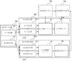
図2Bは、本発明によるハイブリッド測位システムの内部構造を示すブロック図である。 FIG. 2B is a block diagram showing the internal structure of the hybrid positioning system according to the present invention.
図示のように、対象に携帯されたタグ装置201は、RF送信器11および超音波送信器12を含んでいる。RF送信器11およびUS送信器12は、それぞれRF信号および超音波信号を発する。
As illustrated, the
RF測位装置202は、RF信号を受信する複数のRF受信機13−1,13−2,…13−mを含む。
The
上述したように、これらのRF受信機は、検出する空間全体に分散して配列することができる。 As described above, these RF receivers can be distributed and arranged throughout the space to be detected.
RF受信機によって受信されたRF信号は、次に、既存のRF測位方法を用いることにより、対応するRF測位結果(例えばRF信号強度(RSS)ベクトル)を取得するためにRF測位ユニット15に送信される。
The RF signal received by the RF receiver is then transmitted to the
当業者によって知られているように、既存のRF測位方法は主に2つの種類に分類することができる。 As is known by those skilled in the art, existing RF positioning methods can be classified into two main types.
1つは、電波地図(radio map)などのようなRFモジュールに基づいたRSSマッチングアルゴリズムである。 One is an RSS matching algorithm based on an RF module such as a radio map.
他方は、RSS結果を用いることにより対象とRF受信機の間の距離を推測し、それから、三辺測量術方法により対象の位置を計算する方法である。 The other is a method of estimating the distance between the object and the RF receiver by using the RSS result, and then calculating the position of the object by the triangulation method.
一般的な領域について低い精度の測位を行なうために、これらの全てのRF測位方法を同様に本発明に適用することができることは言うまでもない。 It goes without saying that all these RF positioning methods can likewise be applied to the present invention in order to perform low-accuracy positioning for general areas.
以下の説明では、実施例として電波地図に基づいた方法を採用することによって、半教師あり学習アルゴリズムを用いるオンラインRFモジュール(例えば、電波地図)訓練方法(training method)を、本発明の発明ポイントの一部分として説明する。 In the following description, an on-line RF module (eg, radio map) training method using a semi-supervised learning algorithm is adopted by adopting a method based on a radio map as an embodiment. This will be explained as a part.
より詳細な内容については、図7〜図9に関する以下の対応する説明を参照することで理解できるであろう。 More details can be understood with reference to the corresponding description below with respect to FIGS.
RF測位結果(例えばRSSベクトル)は、その後、RF結果メモリ17中に記憶される。
The RF positioning result (for example, RSS vector) is then stored in the
同様に、超音波測位装置203は、超音波信号を受信するための複数の超音波受信機14−1、14−2、・・・14−nを含む。
Similarly, the
上述したように、これらの超音波受信機は、ホットエリア(Hot Area)一帯に密に配列すされる。 As described above, these ultrasonic receivers are densely arranged in a hot area.
超音波受信機によって受信された超音波信号は、対応する超音波測位結果(例えば、TOAベクトル)を取得するために超音波測位ユニット16に送信される。
The ultrasonic signal received by the ultrasonic receiver is transmitted to the
超音波測位結果(例えば、TOAベクトル)は、超音波結果メモリ18中に記憶される。
The ultrasonic positioning result (for example, TOA vector) is stored in the
RF結果メモリ17および超音波結果メモリ18の中に記憶されたRF測位結果および超音波測位結果は、対象の位置を決定するために結果処理装置204で融合される。
The RF positioning result and the ultrasonic positioning result stored in the
対象の最終的に決定した位置は、最終結果メモリ205中に記憶される。
The final determined position of the object is stored in the
一例として、図2Bに示されるように、結果処理装置204および最終結果メモリ205は両方とも、位置情報管理サーバ200内で構成することができる。
As an example, as shown in FIG. 2B, both the
本実施の形態において、結果処理装置204は、TOAベクトルにおける要素の数に従って測位方法を決定する。
In the present embodiment, the
3つ以上のTOAサンプルがあれば、対象の位置は、多辺測量あるいは三角測量方法を用いることによりTOA結果から直ちに決定することができる。 If there are more than two TOA samples, the target position can be immediately determined from the TOA results by using multi-sided or triangulation methods.
TOAサンプルの数が3未満ならば、測位を処理するためにRF結果(例えば、RSSベクトル)を参照する必要がある。 If the number of TOA samples is less than 3, it is necessary to reference an RF result (eg, RSS vector) to process the positioning.
例えば、対象の位置はRF電波地図の探索により決定することができる。 For example, the target position can be determined by searching an RF radio wave map.
図3は、本発明による対象測位方法300を説明するフローチャートである。本発明による対象測位方法300は、2つの段階を含んでいる。設定段階(ステップ301および302)と位置測定段階(ステップ303)である。
FIG. 3 is a flowchart illustrating an
設定段階において、ステップ301で、最初に、検出空間が、「ホットエリア(Hot Area)」と「一般エリア(General Area)」に分けられる。
In the setting stage, in
この領域を分けるための方法は、利用者の要求に基づいて、あるいは何らかのヒューリスティックルール(heuristic rule)従って決めることが可能である。 The method for dividing this area can be determined based on the user's request or according to some heuristic rule.
そして、ステップ302において、分けられた「ホットエリア」および「一般エリア」に従って、測位装置を配列する。
In
本実施の形態において、高精度な測位を必要とする「ホットエリア」については、比較的密に超音波受信機が配列される。一方、低精度の分解能の位置測定を許容する「一般エリア」については、RF、赤外線あるいはWifi受信機が配列される。 In the present embodiment, ultrasonic receivers are arranged relatively densely in a “hot area” that requires highly accurate positioning. On the other hand, an RF, infrared, or WiFi receiver is arranged for a “general area” that allows position measurement with low-resolution resolution.
これらの受信機は、検出範囲が比較的広く、配備コストが比較的安いという効果を提供する。 These receivers provide the advantage of a relatively wide detection range and relatively low deployment costs.
位置測定段階(ステップ303)において、タグ装置を備えた対象が検出空間内に移動している場合、それが超音波によってカバーすることができるホットエリア内であれば、超音波測位がRF測位より高い測位分解能を通常達成することができるので、超音波測位装置がその位置を決定する。 In the position measurement step (step 303), if the target equipped with the tag device has moved into the detection space, if it is in a hot area that can be covered by ultrasonic waves, ultrasonic positioning is performed more than RF positioning. Since a high positioning resolution can usually be achieved, the ultrasonic positioning device determines its position.
対象がホットエリアの外側に移動すれば、対象の位置はトレーニングされたRF電波地図の探索により決定する。 If the object moves outside the hot area, the position of the object is determined by searching a trained RF radio wave map.
図4は、検出空間の区分の具体例を示す。 FIG. 4 shows a specific example of the division of the detection space.
この具体例において、設置されたデスクが「ホットエリア」として定義され、一方、他の空間が「一般エリア」として定義されている。 In this specific example, the installed desk is defined as a “hot area”, while the other space is defined as a “general area”.
図5は、プリインストールされたモニタリングタグの追跡によってホットエリアを修正するフローチャートを示す。 FIG. 5 shows a flow chart for modifying a hot area by tracking pre-installed monitoring tags.
この処理において、超音波測位装置の探知範囲によって「ホットエリア」がカバーされるかどうかが、リアルタイムにモニタされる。 In this process, whether or not the “hot area” is covered by the detection range of the ultrasonic positioning device is monitored in real time.
図6は、具体例として設置されたデスクを用いることによるホットエリアの修正についてさらに説明する。 FIG. 6 further illustrates hot area correction by using a desk installed as a specific example.
図6において、設置されたデスクが「ホットエリア」として調べられる。 In FIG. 6, the installed desk is examined as a “hot area”.
4つのモニタリングタグが、設置されたデスクの全領域に配列され、超音波信号を発する。 Four monitoring tags are arranged in the entire area of the installed desk and emit ultrasonic signals.
超音波測位装置に含まれる超音波受信機は、あらかじめセットされたタイミングで(あるいはランダムに)、モニタリングタグから超音波信号を検出し、検出結果に従って、ホットエリアが超音波測位装置の探知範囲によってカバーされることが保証されるように、超音波受信機の位置を調節する。 The ultrasonic receiver included in the ultrasonic positioning device detects the ultrasonic signal from the monitoring tag at a preset timing (or randomly), and the hot area depends on the detection range of the ultrasonic positioning device according to the detection result. Adjust the position of the ultrasound receiver to ensure that it is covered.
図7は、本発明の第2の実施の形態によるハイブリッド測位システムの構成を示すブロック図である。この第2の実施の形態においては、RF電波地図が、半教師あり学習アルゴリズムによってオンラインでトレーニングされる。 FIG. 7 is a block diagram showing the configuration of the hybrid positioning system according to the second embodiment of the present invention. In this second embodiment, the RF radio wave map is trained online by a semi-supervised learning algorithm.
図8は、RF電波地図トレーニングを説明するフローチャートであり、また、図9は、RF電波地図トレーニングを示す概略図である。 FIG. 8 is a flowchart for explaining RF radio wave map training, and FIG. 9 is a schematic diagram showing RF radio wave map training.
上述したハイブリッド測位システムの構成要素に加えて、図7に示すシステムは、さらに電波地図生成装置701と、電波地図メモリ702を含んでいる。
In addition to the components of the hybrid positioning system described above, the system shown in FIG. 7 further includes a
電波地図生成装置701は、RF測位装置と超音波測位装置から測位結果を取得し、半教師あり学習アルゴリズムを用いることによりRF電波地図をトレーニングする。
The radio wave
対象が一般エリアにある場合、RF電波地図はRF測位を実行するための参照として用いられる。 When the target is in the general area, the RF radio wave map is used as a reference for performing RF positioning.
通常、利用者はタグ装置を携帯し、検出環境内に移動する。 Usually, the user carries the tag device and moves into the detection environment.
タグ装置が超音波とRFの信号を両方とも同時に発するので、2つの信号は両方とも同じ位置に対応する。 Since the tag device emits both ultrasound and RF signals simultaneously, the two signals both correspond to the same location.
n個の超音波受信機とp個のRF受信機がある場合を想定する。 Assume that there are n ultrasonic receivers and p RF receivers.
タグ装置の超音波送信器とRF送信器が、超音波とRFの信号を発する度に、超音波受信機とRF受信機は、例えば、以下に示すような結果ベクトルを取得する。
ここで、toai (1≦ i ≦ n)は、i番目の超音波受信機によって受信されたTOA距離情報を表わし、mは、成功裏にTOA結果を検出した超音波受信機の数である。また、rssj (1≦ j ≦ p)は、j番目のRF受信機によって受信されたRSS情報を表わし、qは成功裏にRSS結果を検出したRF受信機の数である。 Here, toa i (1 ≦ i ≦ n) represents the TOA distance information received by the i-th ultrasonic receiver, and m is the number of ultrasonic receivers that have successfully detected the TOA result. . Also, rss j (1 ≦ j ≦ p) represents RSS information received by the jth RF receiver, and q is the number of RF receivers that have successfully detected the RSS result.
m≦nは、いくつかの超音波受信機が超音波信号を検出するのを妨害する何らかの障害物があることを示しており、また、q≦pは、いくつかのRF受信機からのRSS結果が微弱過ぎて無視できることを示している。 m ≦ n indicates that there are some obstructions that prevent some ultrasound receivers from detecting the ultrasound signal, and q ≦ p indicates that RSS from some RF receivers. The result is too weak to ignore.
図8に示すフローチャートおよび図9に示す概略図に関して、超音波によってカバーされた「ホットエリア」において、対象は超音波測位装置によって位置を決めることができる。 With respect to the flowchart shown in FIG. 8 and the schematic diagram shown in FIG. 9, the object can be positioned by an ultrasonic positioning device in a “hot area” covered by ultrasonic waves.
RF信号については、それぞれのRF受信機でのRF信号強度(RSS)サンプルは、RSSベクトルを形成する。 For RF signals, the RF signal strength (RSS) samples at each RF receiver form an RSS vector.
RSSベクトルのいくつかがホットエリアで受け取られる場合、これらのRSSベクトルは、TOA測位装置によって検出された位置によってラベル付けすることができる。 If some of the RSS vectors are received in the hot area, these RSS vectors can be labeled with the position detected by the TOA positioning device.
また、いくつかの所定の目標位置(例えば、部屋の角)で受け取られるいくつかのRSSベクトルも、対応する所定の位置座標によってラベル付けすることができる。 Also, some RSS vectors received at some predetermined target positions (eg, room corners) can be labeled with corresponding predetermined position coordinates.
もちろん、ベクトルのこの一部は人間のキャリブレーション労力を省くために少ない。 Of course, this part of the vector is small to save human calibration effort.
それらが、超音波有効範囲エリア(例えば一般エリアにおける)の外で受け取られれば、RSSベクトルの残りはラベル付けされていない。 If they are received outside the ultrasound coverage area (eg, in the general area), the rest of the RSS vector is not labeled .
従って、図9に示されるように、我々はラベル付けされたRSSデータとラベル付けされていないRSSデータを有することができる。 Thus, as shown in FIG. 9, we can have labeled RSS data and unlabeled RSS data.
次に、図8に示すように、ラベル付けされたRSSベクトルとラベル付けされていないRSSベクトルは、半教師あり学習アルゴリズムを用いることによりRF電波地図のトレーニングに用いられる。 Next, as shown in FIG. 8, labeled RSS vectors and unlabeled RSS vectors are used for RF radio wave map training by using a semi-supervised learning algorithm.
半教師あり学習アルゴリズムは、一般に大量のラベル付けされていないデータで少ない量のラベル付けされたデータを学習するために、ラベル付けされたデータとラベル付けされていないデータの両方を利用するマシン学習技術のクラスである。 Semi-supervised learning algorithm to learn the general amount of labeled data less in data that has not been mass-labeling, machine learning that utilizes both data unlabeled data labeled It is a technical class.
半教師あり学習アルゴリズムについては、当業者によって周知であるので、その詳細についてここでは述べない。 Since the semi-supervised learning algorithm is well known by those skilled in the art, its details are not described here.
RSSベクトルが超音波測位システムによってラベル付けされるので、RF電波地図はオンライン方法でトレーニングすることができる。 Since the RSS vector is labeled by the ultrasound positioning system, the RF radio map can be trained in an online manner.
トレーニング後のRF電波地図は、位置測定工程中に対象の測位に用いることができる。 The RF radio wave map after training can be used for positioning the target during the position measurement process.
本実施の形態において、対象の位置は、例えば、以下の融合測位法に基づいて推定することができる。 In the present embodiment, the target position can be estimated based on, for example, the following fusion positioning method.
m≧3であれば、[toa1,toa2,・・・,toam]ベクトルだけが、極めて正確な測位のために三辺測量あるいは多辺測量アルゴリズムによって利用される。 If m ≧ 3, only the [toa 1 , toa 2 ,..., toa m ] vector is used by the trilateration or multi-sided survey algorithm for extremely accurate positioning.
m<3であれば、[rss1, rss2,・・・, rssa]ベクトルだけが、オフライン学習アルゴリズムによってトレーニングされたRF電波地図を探索するために利用される。この方法によって得られる測位精度は比較的低い。しかし、高精度な測位を必要としない「一般エリア」にとっては、そのことは許容される。 If m <3, only the [rss 1 , rss 2 ,..., rss a ] vector is used to search the RF radio wave map trained by the offline learning algorithm. The positioning accuracy obtained by this method is relatively low. However, this is allowed for a “general area” that does not require highly accurate positioning.
図10は、電波地図生成装置701の内部構成を示す。
FIG. 10 shows the internal configuration of the
図8に示すローチャートと図9に示す概略図を参照すると、電波地図生成装置701は、結果取得ユニット71を介して、RF測位装置および超音波測位装置によってそれぞれ提供される低い精度の測位結果(例えば、RSSベクトル)および高い精度の測位結果(例えば、TOAベクトル)を取得する。
Referring to the flowchart shown in FIG. 8 and the schematic diagram shown in FIG. 9, the
次に、対象がホットエリアにあれば、結果分類ユニット72で、超音波測位装置によって取得されたTOA結果はRSS結果をラベル付けすることができる。
Next, if the object is in the hot area, the
RSS結果は、超音波測位装置によって取得されたTOA結果によってラベル付けされる。
ラベル付けされたRSS結果とラベル付けされていないRSS結果は両方とも、電波地図生成ユニット73に提供される。
The RSS result is labeled with the TOA result obtained by the ultrasonic positioning device.
Both labeled RSS results and unlabeled RSS results are provided to the radio
電波地図生成ユニット73で、電波地図は、半教師あり学習アルゴリズムによって生成される。
In the radio
最後に、図11は、本発明による第1と第2実施の形態を組み合わせたハイブリッド測位システムの内部構成を示すブロック図である。 Finally, FIG. 11 is a block diagram showing an internal configuration of a hybrid positioning system combining the first and second embodiments according to the present invention.
図11に示すシステムにおいて、対象の位置を計算しながらリアルタイムにRF電波地図を修正する電波地図補正装置703をさらに含んでいる。 The system shown in FIG. 11 further includes a radio wave map correction device 703 that corrects the RF radio wave map in real time while calculating the position of the target.
すなわち、リアルタイムに超音波測位装置の位置測定結果を参照することにより、RF電波地図のコンテンツが修正されあるいは調整される。 That is, the content of the RF radio wave map is corrected or adjusted by referring to the position measurement result of the ultrasonic positioning device in real time.
上述した説明では、本発明によるハイブリッド測位システムと、ハイブリッド測位システムを用いることにより適応性のある分解能を備えた対象の測位方法について、添付図面を参照して詳細に説明した。 In the above description, the hybrid positioning system according to the present invention and the target positioning method having adaptive resolution by using the hybrid positioning system have been described in detail with reference to the accompanying drawings.
上記説明によって、本発明が以下の有益な効果を実現できることが理解されるであろう。 From the above description, it will be understood that the present invention can realize the following beneficial effects.
測位融合アルゴリズムに基づいて、本発明によるシステムは、異なる適用エリアにおいて適応性のある測位分解能を提供することができる。 Based on the positioning fusion algorithm, the system according to the invention can provide adaptive positioning resolution in different application areas.
また、適用環境全体をカバーするために超音波受信機を密な配列で配置する必要がないので、システムコストは軽減することができる。 In addition, since it is not necessary to arrange the ultrasonic receivers in a dense array in order to cover the entire application environment, the system cost can be reduced.
さらに、ホットエリアに配置された超音波測位装置のために、RFモジュール(電波地図)はオンラインでトレーニングすることができる。
このため、システムはより少ないキャリブレーションを必要とする。
Furthermore, RF modules (radio wave maps) can be trained online for ultrasonic positioning devices located in the hot area.
For this reason, the system requires less calibration.
本発明においては、利用者の要求あるいはヒューリスティックルールに基づいて「ホットエリア」および「一般エリア」を分けるのは簡単である。また、より正確にホットエリアをカバーするように、超音波測位システムを調節することは簡単である。 In the present invention, it is easy to separate the “hot area” and the “general area” based on the user's request or heuristic rule. It is also easy to adjust the ultrasound positioning system to cover the hot area more accurately.
上述した実施の形態において、幾つかの特定のステップを例として示しかつ説明している。 In the embodiments described above, some specific steps are shown and described as examples.
しかしながら、本発明の方法の工程は、これらの特定のステップに限定されない。 However, the process steps of the present invention are not limited to these specific steps.
当業者であれば、これらのステップを変更し、修正し、補完することができること、そしていくつかのステップの順番を、本発明の精神および本質的な特徴から外れずに変更することができることを十分に理解するであろう。 Those skilled in the art will understand that these steps can be changed, modified and supplemented, and that the order of several steps can be changed without departing from the spirit and essential characteristics of the invention. You will fully understand.
以上、特定の実施の形態を参照して本発明を説明したが、本発明は、図面中で示される上記の特定の実施の形態および特定の構成に限定されない。例えば、示されたいくつかの構成要素は、1つの構成要素としてお互いと組み合わせるかもしれない。あるいは、1つの構成要素はいくつかのサブコンポーネントに分割されるかもしれないし、他の既知の構成要素も加えられるかもしれない。動作処理も実施例において示されるものに限定されない。当業者は、本発明が、本発明の精神および本質的な機能から外れずに、他の特定の形態で実装可能であることを理解するであろう。従って、現在の実施の形態は、全ての点において例示でありかつ限定的でないとして考慮されるべきである。本発明の範囲は、前述の説明によってではなく添付された請求項によって示される。また、したがって、請求項と同等の意味と範囲の内で生ずる変更は全て本発明の範囲に包含される。 Although the present invention has been described above with reference to specific embodiments, the present invention is not limited to the specific embodiments and specific configurations shown in the drawings. For example, some of the components shown may be combined with each other as one component. Alternatively, one component may be divided into several subcomponents and other known components may be added. The operation process is not limited to that shown in the embodiment. Those skilled in the art will appreciate that the present invention can be implemented in other specific forms without departing from the spirit and essential function of the invention. Accordingly, the current embodiment is to be considered in all respects as illustrative and not restrictive. The scope of the invention is indicated by the appended claims rather than by the foregoing description. Accordingly, all modifications that come within the meaning and range equivalent to the terms of the claims are included in the scope of the present invention.
101:超音波タグ装置
102:超音波測位装置
200:位置情報管理サーバ
201:タグ装置
202:RF測位装置
203:超音波測位装置
204:結果処理装置
205:最終結果メモリ
11:RF送信器
12:超音波送信器
13−1、13−p:RF受信機
14−1、14−p:超音波受信機
15:RF測位ユニット
16:超音波測位ユニット
17:RF結果メモリ
18:超音波結果メモリ
701:電波地図生成装置
702:電波地図メモリ
71:結果取得ユニット
72:結果分類ユニット
73:電波地図生成ユニット
703:電波地図補正装置
DESCRIPTION OF SYMBOLS 101: Ultrasonic tag apparatus 102: Ultrasonic positioning apparatus 200: Position information management server 201: Tag apparatus 202: RF positioning apparatus 203: Ultrasonic positioning apparatus 204: Result processing apparatus 205: Final result memory 11: RF transmitter 12: Ultrasonic transmitter 13-1, 13-p: RF receiver 14-1, 14-p: Ultrasonic receiver 15: RF positioning unit 16: Ultrasonic positioning unit 17: RF result memory 18: Ultrasonic result memory 701 : Radio wave map generation device 702: Radio wave map memory 71: Result acquisition unit 72: Result classification unit 73: Radio wave map generation unit 703: Radio wave map correction device
Claims (13)
検出空間をホットエリアおよび一般エリアに分けるステップと、
ホットエリアおよび一般エリアの位置に従って、前記ホットエリアをカバーする検出範囲を有する高解像度位置信号受信機および前記空間をカバーする検出範囲を有する低解像度位置信号受信機を配置するステップと、
前記空間内で対象が移動すると、前記高解像度位置信号送受信機と前記低解像度位置信号送受信機からの検出結果を融合し、適応性のある分解能で対象の位置を決定するステップとを有し、
前記高解像度位置信号受信機の検出範囲によってホットエリアが確実にカバーされるように、前記高解像度位置信号受信機の位置を調節するホットエリア調節ステップと、
低解像度測位において測位参照として用いられる電波地図を生成するステップとを有し、
前記対象が、高解像度位置信号および低解像度位置信号を送信し、
前記ホットエリア調節ステップが、
前記ホットエリアのエッジに、前記高解像度位置信号を送信する複数のモニター装置を設置するステップと、
前記高解像度位置信号受信機によって前記モニター装置から高解像度位置信号を受信するステップと、
高解像度位置信号受信機の検出範囲によってホットエリアが確実にカバーされるように、受信した高解像度位置信号によって高解像度位置信号受信機の位置を調節するステップを含み、
前記電波地図を生成するステップが、
複数の位置における前記対象の低解像度位置信号及び高解像度位置信号の測位結果を取得するステップと、
前記対象の位置がホットエリア内である場合、高解像度位置信号の測位結果により得られた位置を、低解像度位置信号の検出結果にラベル付けするステップと、
ラベル付けされた低解像度位置信号の検出結果とラベル付けされていない低解像度位置信号の検出結果とに基づいて、半教師あり学習方法を利用して電波地図を生成するステップとを含む
ことを特徴とする対象測位方法。 A target positioning method with adaptive resolution,
Dividing the detection space into a hot area and a general area;
According to the position of the hot area and general areas, placing a low-resolution position signal receiver apparatus having a high resolution position signal receiver unit and detection range covering said space having a detection range covering the hot area ,
Fusing detection results from the high resolution position signal transceiver and the low resolution position signal transceiver when the object moves in the space, and determining the position of the object with adaptive resolution,
As hot area is reliably covered by the detection range of the high resolution position signal receiver unit, the hot area adjusting step of adjusting the position of the high resolution position signal receiver apparatus,
Generating a radio wave map used as a positioning reference in low-resolution positioning ,
The object transmits a high resolution position signal and a low resolution position signal;
The hot area adjustment step includes:
Installing a plurality of monitoring devices that transmit the high-resolution position signal at an edge of the hot area;
Receiving a high-resolution position signal from the monitoring device by the high resolution position signal receiver apparatus,
The detection range of the high-resolution position signal receiver unit as hot area is reliably cover, seen including the step of adjusting the position of the high resolution position signal receiver apparatus by a high-resolution position signals received,
Generating the radio wave map comprises:
Obtaining positioning results of the low resolution position signal and the high resolution position signal of the object at a plurality of positions;
If the target position is within a hot area, labeling the position obtained from the positioning result of the high resolution position signal with the detection result of the low resolution position signal;
Generating a radio wave map using a semi-supervised learning method based on the detection result of the labeled low-resolution position signal and the detection result of the unlabeled low-resolution position signal. Target positioning method.
前記対象が前記ホットエリアに位置する場合、前記高解像度位置信号受信機の検出結果に従って前記対象の位置を決定し、
前記対象が一般エリアに位置する場合に、前記低解像度位置信号受信機の検出結果で電波地図を探索することにより、対象の位置を決定することを特徴とする請求項1に記載の対象測位方法。 Determining the position of the object comprises:
If the object is located in the hot area, determine the position of the object according to the detection result of the high-resolution position signal receiver;
The target positioning method according to claim 1, wherein, when the target is located in a general area, the target position is determined by searching a radio wave map based on a detection result of the low-resolution position signal receiver. .
前記対象の位置を決定するステップが、
TOAベクトルに含まれる要素の数が3以上であれば、TOAベクトルによって対象の位置を計算するステップと、
TOAベクトルに含まれる要素の数が3未満であれば、電波地図の探索により対象の位置を決定するステップを含むことを特徴とする請求項4に記載の対象測位方法。 A plurality of the high resolution position signal receivers receive high resolution position signals from the object to generate a TOA vector;
Determining the position of the object comprises:
If the number of elements contained in the TOA vector is 3 or more, calculating the target position by the TOA vector;
The target positioning method according to claim 4, further comprising a step of determining a target position by searching a radio wave map if the number of elements included in the TOA vector is less than three .
対象に保持され、高解像度位置信号を送信する高解像度位置信号送信機と、低解像度位置信号を送信する低解像度位置信号送信機とを含むタグ装置と、
前記高解像度位置信号を受信する高解像度位置信号受信機を含む高解像度測位装置と、
前記低解像度位置信号を受信する低解像度位置信号受信機を含む低解像度測位装置と、
前記高解像度測位装置および前記低解像度測位装置からの検出結果を融合し、適応性のある分解能で対象の位置を決定する結果処理装置とを備え、
検出空間が、ホットエリアおよび一般エリアに分けられ、前記低解像度測位装置の検出範囲が前記空間をカバーし、前記高解像度測位装置の検出範囲がホットエリアをカバーし、
前記高解像度測位装置が、
前記ホットエリアのエッジに設置されたモニター装置から受信した前記高解像度位置信号に基づいて、前記ホットエリアが前記高解像度測位装置の探知範囲によってカバーされることが保証されるように前記高解像度位置信号受信機の位置を調節するホットエリア調節手段を含み、
前記低解像度測位装置の測位参照に用いられる電波地図を生成する電波地図生成装置を備え、
前記電波地図生成装置が、
複数の位置における前記タグ装置の低解像度位置信号及び高解像度位置信号の測位結果を取得する結果取得ユニットと、
前記タグ装置の位置がホットエリア内である場合、高解像度位置信号の測位結果により得られた位置を、低解像度位置信号の検出結果にラベル付けする結果分類ユニットと、
ラベル付けされた低解像度位置信号の検出結果とラベル付けされていない低解像度位置信号の検出結果とに基づいて、半教師あり学習方法を利用して電波地図を生成する電波地図生成ユニットとを備える
ことを特徴とする対象測位システム。 A target positioning system with adaptive resolution,
A tag device including a high-resolution position signal transmitter that is held by an object and transmits a high-resolution position signal; and a low-resolution position signal transmitter that transmits a low-resolution position signal;
A high-resolution positioning device including a high-resolution position signal receiver for receiving the high-resolution position signal;
A low-resolution positioning device including a low-resolution position signal receiver for receiving the low-resolution position signal;
A result processing device that fuses the detection results from the high-resolution positioning device and the low-resolution positioning device and determines the position of the object with an adaptive resolution;
The detection space is divided into a hot area and a general area, the detection range of the low-resolution positioning device covers the space, the detection range of the high-resolution positioning device covers the hot area,
The high-resolution positioning device is
Based on the high-resolution position signal received from the monitor device installed at the edge of the hot area, the high-resolution position is guaranteed so that the hot area is covered by the detection range of the high-resolution positioning device. Including hot area adjustment means for adjusting the position of the signal receiver;
A radio map generating device that generates a radio map used for positioning reference of the low resolution positioning device;
The radio wave map generator is
A result acquisition unit for acquiring positioning results of the low resolution position signal and the high resolution position signal of the tag device at a plurality of positions;
When the position of the tag device is in a hot area, a result classification unit for labeling the position obtained by the positioning result of the high resolution position signal to the detection result of the low resolution position signal;
A radio map generation unit that generates a radio map using a semi-supervised learning method based on a detection result of a labeled low resolution position signal and a detection result of an unlabeled low resolution position signal
Target positioning system characterized by that .
前記対象が前記ホットエリアに位置する場合、前記高解像度測位装置の前記高解像度位置信号受信機の検出結果に従って前記対象の位置を決定し、
前記対象が一般エリアに位置する場合に、前記低解像度測位装置の前記低解像度位置信号受信機の検出結果で電波地図を探索することにより、対象の位置を決定することを特徴とする請求項8に記載の対象測位システム。 The result processing device is
If the object is located in the hot area, determine the position of the object according to the detection result of the high-resolution position signal receiver of the high-resolution positioning device;
9. The position of the target is determined by searching a radio wave map with a detection result of the low resolution position signal receiver of the low resolution positioning device when the target is located in a general area. Target positioning system described in .
Applications Claiming Priority (2)
| Application Number | Priority Date | Filing Date | Title |
|---|---|---|---|
| CN200810161869A CN101718859A (en) | 2008-10-09 | 2008-10-09 | Method and system for positioning target by adaptive resolution |
| CN200810161869.9 | 2008-10-09 |
Publications (3)
| Publication Number | Publication Date |
|---|---|
| JP2010107501A JP2010107501A (en) | 2010-05-13 |
| JP2010107501A5 JP2010107501A5 (en) | 2012-07-05 |
| JP5225242B2 true JP5225242B2 (en) | 2013-07-03 |
Family
ID=42098382
Family Applications (1)
| Application Number | Title | Priority Date | Filing Date |
|---|---|---|---|
| JP2009220184A Expired - Fee Related JP5225242B2 (en) | 2008-10-09 | 2009-09-25 | Target positioning method and target positioning system with adaptive resolution |
Country Status (3)
| Country | Link |
|---|---|
| US (1) | US20100090899A1 (en) |
| JP (1) | JP5225242B2 (en) |
| CN (1) | CN101718859A (en) |
Cited By (1)
| Publication number | Priority date | Publication date | Assignee | Title |
|---|---|---|---|---|
| US9949089B2 (en) | 2015-05-13 | 2018-04-17 | Ricoh Company, Ltd. | Position management system, position management apparatus, and position management method |
Families Citing this family (48)
| Publication number | Priority date | Publication date | Assignee | Title |
|---|---|---|---|---|
| CN101115124B (en) * | 2006-07-26 | 2012-04-18 | 日电(中国)有限公司 | Method and apparatus for identifying media program based on audio watermark |
| MX2012012639A (en) * | 2010-05-07 | 2013-03-07 | Siemens Entpr Communications | Spatial arrangement of a plurality of communication devices and method for determining the spatial position of a device. |
| FI122328B (en) * | 2010-08-18 | 2011-12-15 | Sauli Hepo-Oja | Active localization system |
| US8174931B2 (en) | 2010-10-08 | 2012-05-08 | HJ Laboratories, LLC | Apparatus and method for providing indoor location, position, or tracking of a mobile computer using building information |
| US20120226453A1 (en) * | 2011-03-02 | 2012-09-06 | General Electric Company | Circuit breaker trip unit |
| US8981995B2 (en) | 2011-06-03 | 2015-03-17 | Microsoft Technology Licensing, Llc. | Low accuracy positional data by detecting improbable samples |
| US9470529B2 (en) | 2011-07-14 | 2016-10-18 | Microsoft Technology Licensing, Llc | Activating and deactivating sensors for dead reckoning |
| JP5974005B2 (en) * | 2011-08-05 | 2016-08-23 | パナソニック インテレクチュアル プロパティ コーポレーション オブ アメリカPanasonic Intellectual Property Corporation of America | Positioning server device and positioning control method |
| US10184798B2 (en) | 2011-10-28 | 2019-01-22 | Microsoft Technology Licensing, Llc | Multi-stage dead reckoning for crowd sourcing |
| CN102662159B (en) * | 2012-04-25 | 2014-01-15 | 东北大学 | Method and system of reflection-type indoor positioning |
| US9817125B2 (en) | 2012-09-07 | 2017-11-14 | Microsoft Technology Licensing, Llc | Estimating and predicting structures proximate to a mobile device |
| US9310462B2 (en) | 2012-09-07 | 2016-04-12 | Microsoft Technology Licensing, Llc | Locating a mobile computing device in an indoor environment |
| CN102967848B (en) * | 2012-11-28 | 2014-04-02 | 电子科技大学 | Positioning method based on distance relationship library and received signal intensity |
| US9380425B2 (en) | 2013-12-05 | 2016-06-28 | At&T Mobility Ii Llc | Systems, methods, and computer-readable storage devices for generating and using a radio-frequency map of an area |
| US10509096B2 (en) | 2014-05-09 | 2019-12-17 | Microsoft Technology Licensing, Llc | Location error radius determination |
| US9918202B2 (en) | 2014-05-12 | 2018-03-13 | Microsoft Technology Licensing, Llc | Adaptive position determination |
| CN104076323A (en) * | 2014-07-14 | 2014-10-01 | 成都联星微电子有限公司 | RFID positioning method based on simulation tag |
| CN104111072A (en) * | 2014-07-28 | 2014-10-22 | 福建星网视易信息系统有限公司 | Method, device and system for navigation in building |
| KR101554232B1 (en) * | 2014-10-08 | 2015-09-21 | 주식회사 조이코퍼레이션 | Terminal Positioning Apparatus and Method, and Terminal Positioning System Using the Same |
| CN104614705A (en) * | 2014-12-12 | 2015-05-13 | 陈冲 | Indoor locating and orientating method based on ultrasonic wave, wifi and big data analyzing technology |
| CN105828430A (en) | 2015-01-08 | 2016-08-03 | 阿里巴巴集团控股有限公司 | Information acquisition and processing method, client and server |
| CN104656075A (en) * | 2015-01-28 | 2015-05-27 | 广州视源电子科技股份有限公司 | Indoor positioning method and system |
| CN104640073B (en) * | 2015-02-09 | 2018-07-24 | 江南大学 | A kind of wifi wireless location methods and system based on reverse synchronous perception |
| KR101726677B1 (en) * | 2015-04-29 | 2017-04-14 | 국방과학연구소 | Wireless sensor network device and method for controlling the same |
| US9743252B2 (en) * | 2015-06-11 | 2017-08-22 | Honeywell International Inc. | System and method for locating devices in predetermined premises |
| KR101882845B1 (en) * | 2015-08-17 | 2018-07-30 | 울산대학교 산학협력단 | System and method for position measurement |
| EP3354047B1 (en) * | 2015-09-25 | 2019-11-06 | Telefonaktiebolaget LM Ericsson (PUBL) | Method for measurement reporting resolution adaptation |
| US20170131402A1 (en) * | 2015-11-06 | 2017-05-11 | Mitsubishi Electric Research Laboratories, Inc. | System and Method for Augmented Localization of WiFi Devices |
| KR101751805B1 (en) | 2016-03-03 | 2017-06-29 | 전자부품연구원 | E-zigbee with complex postioning fuction and device and method for indoor postioning using the same |
| US11567201B2 (en) | 2016-03-11 | 2023-01-31 | Kaarta, Inc. | Laser scanner with real-time, online ego-motion estimation |
| WO2019018315A1 (en) * | 2017-07-17 | 2019-01-24 | Kaarta, Inc. | Aligning measured signal data with slam localization data and uses thereof |
| US10989542B2 (en) | 2016-03-11 | 2021-04-27 | Kaarta, Inc. | Aligning measured signal data with slam localization data and uses thereof |
| US11573325B2 (en) | 2016-03-11 | 2023-02-07 | Kaarta, Inc. | Systems and methods for improvements in scanning and mapping |
| JP6987797B2 (en) | 2016-03-11 | 2022-01-05 | カールタ インコーポレイテッド | Laser scanner with real-time online egomotion estimation |
| CN106291463B (en) * | 2016-07-27 | 2018-10-23 | 南京崇山通信科技有限公司 | A kind of indoor orientation method combined based on WiFi and sound wave |
| CN106403955A (en) * | 2016-10-13 | 2017-02-15 | 北京国承万通信息科技有限公司 | Positioning method and positioning system |
| US9949083B1 (en) * | 2016-10-18 | 2018-04-17 | Cisco Technology, Inc. | Precise, high coverage, location system |
| KR102150276B1 (en) * | 2017-09-13 | 2020-09-01 | 한국전자통신연구원 | Finger print constructing method for radio map in communication network and apparatus therefor |
| CN107976190A (en) * | 2017-11-10 | 2018-05-01 | 北京金坤科创技术有限公司 | A kind of indoor positioning air navigation aid and Intelligent unattended foreground system on duty |
| WO2019099605A1 (en) | 2017-11-17 | 2019-05-23 | Kaarta, Inc. | Methods and systems for geo-referencing mapping systems |
| US10712804B2 (en) | 2017-12-19 | 2020-07-14 | Intel Corporation | Dynamic selection of display resolution |
| WO2019165194A1 (en) | 2018-02-23 | 2019-08-29 | Kaarta, Inc. | Methods and systems for processing and colorizing point clouds and meshes |
| WO2020009826A1 (en) | 2018-07-05 | 2020-01-09 | Kaarta, Inc. | Methods and systems for auto-leveling of point clouds and 3d models |
| CN110176167B (en) * | 2019-05-31 | 2021-04-06 | 垂欧教科设备(上海)有限公司 | Indoor intelligent teaching aid system based on RFID and operation method thereof |
| EP3798918A1 (en) * | 2019-09-26 | 2021-03-31 | Naver Corporation | Using semi-supervised variational autoencoder for wi-fi-based indoor localization |
| JP2021139734A (en) * | 2020-03-05 | 2021-09-16 | サトーホールディングス株式会社 | Information processing device, information processing system, program, and information processing method |
| US11808873B2 (en) | 2020-04-03 | 2023-11-07 | Western Washington University | Systems and methods for locating tagged objects in remote regions |
| CN113891298B (en) * | 2021-09-29 | 2024-02-27 | 安徽江淮汽车集团股份有限公司 | Bluetooth key positioning method for vehicle |
Family Cites Families (12)
| Publication number | Priority date | Publication date | Assignee | Title |
|---|---|---|---|---|
| JPH05297117A (en) * | 1992-04-21 | 1993-11-12 | Taitetsuku:Kk | Position sensing display system |
| JPH0798378A (en) * | 1993-09-28 | 1995-04-11 | Shin Kobe Electric Mach Co Ltd | Proximity sensor |
| JP3165391B2 (en) * | 1996-03-22 | 2001-05-14 | 松下電器産業株式会社 | Mobile radio communication system and method for detecting position of mobile station |
| US6466938B1 (en) * | 2000-07-31 | 2002-10-15 | Motorola, Inc. | Method and apparatus for locating a device using a database containing hybrid location data |
| US6838992B2 (en) * | 2003-03-21 | 2005-01-04 | Versus Technology, Inc. | Methods and systems for locating subjects and providing event notification within a tracking environment and badge for use therein |
| WO2005041142A2 (en) * | 2003-10-20 | 2005-05-06 | Radianse, Inc. | A location system for associating a first signal with a second signal |
| JP2005331434A (en) * | 2004-05-21 | 2005-12-02 | Omron Corp | Measuring device, measurement method, measuring system, reader/writer, data processing method, recording medium, and program |
| CN1809210A (en) * | 2005-01-17 | 2006-07-26 | 广州天润信息科技有限公司 | Mobile terminal positioning and programmable service method |
| CN1841084B (en) * | 2005-03-29 | 2011-12-07 | 松下电器产业株式会社 | Mixed distance measuring method |
| US7899006B2 (en) * | 2006-12-05 | 2011-03-01 | Zebra Enterprise Solutions Corp. | Location system for wireless local area network (WLAN) using RSSI and time difference of arrival (TDOA) processing |
| US20090189810A1 (en) * | 2008-01-24 | 2009-07-30 | Broadcom Corporation | Weighted aiding for positioning systems |
| US7796471B2 (en) * | 2008-02-20 | 2010-09-14 | Intelligent Sciences, Ltd. | Ultrasonic in-building positioning system based on phase difference array with ranging |
-
2008
- 2008-10-09 CN CN200810161869A patent/CN101718859A/en active Pending
-
2009
- 2009-09-25 JP JP2009220184A patent/JP5225242B2/en not_active Expired - Fee Related
- 2009-09-25 US US12/567,572 patent/US20100090899A1/en not_active Abandoned
Cited By (2)
| Publication number | Priority date | Publication date | Assignee | Title |
|---|---|---|---|---|
| US9949089B2 (en) | 2015-05-13 | 2018-04-17 | Ricoh Company, Ltd. | Position management system, position management apparatus, and position management method |
| US10028103B2 (en) | 2015-05-13 | 2018-07-17 | Ricoh Company, Ltd. | Position management system, position management apparatus, position management method, and non-transitory computer-readable information recording medium |
Also Published As
| Publication number | Publication date |
|---|---|
| US20100090899A1 (en) | 2010-04-15 |
| CN101718859A (en) | 2010-06-02 |
| JP2010107501A (en) | 2010-05-13 |
Similar Documents
| Publication | Publication Date | Title |
|---|---|---|
| JP5225242B2 (en) | Target positioning method and target positioning system with adaptive resolution | |
| Dabove et al. | Indoor positioning using Ultra-wide band (UWB) technologies: Positioning accuracies and sensors' performances | |
| Bulusu et al. | GPS-less low-cost outdoor localization for very small devices | |
| Farid et al. | Recent advances in wireless indoor localization techniques and system | |
| Varshavsky et al. | � Location in Ubiquitous Computing | |
| JP5026086B2 (en) | TDOA / GPS hybrid wireless position detection system | |
| Chang et al. | Spinning beacons for precise indoor localization | |
| US9063208B2 (en) | Assisted global navigation satellite system for indoor positioning | |
| JP2010107501A5 (en) | ||
| JP2021519422A (en) | Network architecture and methods for location services | |
| US20090102707A1 (en) | Systems and methods for transparency mapping using multipath signals | |
| EP3371620B1 (en) | Method for registering location of device and device | |
| JP2010151807A (en) | Radio measuring apparatus and coordinate constituting method | |
| CN102932742A (en) | Method and system for indoor positioning based on inertial sensor and wireless signal characteristics | |
| Chabbar et al. | Indoor localization using Wi-Fi method based on Fingerprinting Technique | |
| JP2010197050A (en) | Position estimating system | |
| Abdat et al. | Survey on indoor wireless positioning techniques: Towards adaptive systems | |
| Mazan et al. | A Study of Devising Neural Network Based Indoor Localization Using Beacons: First Results. | |
| CN109379707A (en) | A kind of recognition methods of indoor objects zone of action and system based on wireless signal | |
| JP6610963B2 (en) | Method, communication system, and reader for positioning user equipment | |
| EP3232220B1 (en) | Method and device for estimating accuracy of a position determination | |
| Xu et al. | Variance-based fingerprint distance adjustment algorithm for indoor localization | |
| Tsai et al. | Location Tracking and Forensic Analysis of Criminal Suspects’ Footprints | |
| Gikas et al. | Full-scale testing and performance evaluation of an active RFID system for positioning and personal mobility | |
| KR101317338B1 (en) | Apparatus for measuring indoor wave environment and method for measuring indoor wave environment using the same |
Legal Events
| Date | Code | Title | Description |
|---|---|---|---|
| A521 | Request for written amendment filed |
Free format text: JAPANESE INTERMEDIATE CODE: A523 Effective date: 20100610 |
|
| A131 | Notification of reasons for refusal |
Free format text: JAPANESE INTERMEDIATE CODE: A131 Effective date: 20110905 |
|
| A521 | Request for written amendment filed |
Free format text: JAPANESE INTERMEDIATE CODE: A523 Effective date: 20111202 |
|
| A131 | Notification of reasons for refusal |
Free format text: JAPANESE INTERMEDIATE CODE: A131 Effective date: 20120221 |
|
| A524 | Written submission of copy of amendment under article 19 pct |
Free format text: JAPANESE INTERMEDIATE CODE: A524 Effective date: 20120521 |
|
| TRDD | Decision of grant or rejection written | ||
| A01 | Written decision to grant a patent or to grant a registration (utility model) |
Free format text: JAPANESE INTERMEDIATE CODE: A01 Effective date: 20130301 |
|
| A61 | First payment of annual fees (during grant procedure) |
Free format text: JAPANESE INTERMEDIATE CODE: A61 Effective date: 20130312 |
|
| R150 | Certificate of patent or registration of utility model |
Free format text: JAPANESE INTERMEDIATE CODE: R150 |
|
| FPAY | Renewal fee payment (event date is renewal date of database) |
Free format text: PAYMENT UNTIL: 20160322 Year of fee payment: 3 |
|
| R250 | Receipt of annual fees |
Free format text: JAPANESE INTERMEDIATE CODE: R250 |
|
| LAPS | Cancellation because of no payment of annual fees |