JP5221827B1 - Stereoscopic image capturing apparatus and zoom operation control method - Google Patents
Stereoscopic image capturing apparatus and zoom operation control method Download PDFInfo
- Publication number
- JP5221827B1 JP5221827B1 JP2013502314A JP2013502314A JP5221827B1 JP 5221827 B1 JP5221827 B1 JP 5221827B1 JP 2013502314 A JP2013502314 A JP 2013502314A JP 2013502314 A JP2013502314 A JP 2013502314A JP 5221827 B1 JP5221827 B1 JP 5221827B1
- Authority
- JP
- Japan
- Prior art keywords
- zoom
- image
- parallax
- speed
- controller
- Prior art date
- Legal status (The legal status is an assumption and is not a legal conclusion. Google has not performed a legal analysis and makes no representation as to the accuracy of the status listed.)
- Expired - Fee Related
Links
Images


Classifications
-
- G—PHYSICS
- G03—PHOTOGRAPHY; CINEMATOGRAPHY; ANALOGOUS TECHNIQUES USING WAVES OTHER THAN OPTICAL WAVES; ELECTROGRAPHY; HOLOGRAPHY
- G03B—APPARATUS OR ARRANGEMENTS FOR TAKING PHOTOGRAPHS OR FOR PROJECTING OR VIEWING THEM; APPARATUS OR ARRANGEMENTS EMPLOYING ANALOGOUS TECHNIQUES USING WAVES OTHER THAN OPTICAL WAVES; ACCESSORIES THEREFOR
- G03B35/00—Stereoscopic photography
- G03B35/08—Stereoscopic photography by simultaneous recording
-
- H—ELECTRICITY
- H04—ELECTRIC COMMUNICATION TECHNIQUE
- H04N—PICTORIAL COMMUNICATION, e.g. TELEVISION
- H04N13/00—Stereoscopic video systems; Multi-view video systems; Details thereof
- H04N13/20—Image signal generators
- H04N13/204—Image signal generators using stereoscopic image cameras
- H04N13/207—Image signal generators using stereoscopic image cameras using a single 2D image sensor
-
- H—ELECTRICITY
- H04—ELECTRIC COMMUNICATION TECHNIQUE
- H04N—PICTORIAL COMMUNICATION, e.g. TELEVISION
- H04N23/00—Cameras or camera modules comprising electronic image sensors; Control thereof
- H04N23/60—Control of cameras or camera modules
- H04N23/69—Control of means for changing angle of the field of view, e.g. optical zoom objectives or electronic zooming
-
- G—PHYSICS
- G03—PHOTOGRAPHY; CINEMATOGRAPHY; ANALOGOUS TECHNIQUES USING WAVES OTHER THAN OPTICAL WAVES; ELECTROGRAPHY; HOLOGRAPHY
- G03B—APPARATUS OR ARRANGEMENTS FOR TAKING PHOTOGRAPHS OR FOR PROJECTING OR VIEWING THEM; APPARATUS OR ARRANGEMENTS EMPLOYING ANALOGOUS TECHNIQUES USING WAVES OTHER THAN OPTICAL WAVES; ACCESSORIES THEREFOR
- G03B2205/00—Adjustment of optical system relative to image or object surface other than for focusing
- G03B2205/0046—Movement of one or more optical elements for zooming
Abstract
立体視用の映像を撮影するデジタルカメラ(100)であって、被写体の光学像を形成する光学系(110A及び110B)と、前記光学像から、前記立体視用の映像を構成する第1及び第2視点画像(151A及び151B)を生成するCCDイメージセンサ(150A及び150B)と、光学系(110A及び110B)のズーム動作を制御するコントローラ(210)とを備え、コントローラ(210)は、前記2枚の画像における視差量に基づいて、第1の速度で前記ズーム動作を実行する第1動作と、前記第1の速度よりも遅い第2の速度で前記ズーム動作を実行する第2動作とを選択的に切り替えて実行する。 A digital camera (100) that captures a stereoscopic video, an optical system (110A and 110B) that forms an optical image of a subject, and a first and a first video that constitute the stereoscopic video from the optical image A CCD image sensor (150A and 150B) that generates a second viewpoint image (151A and 151B), and a controller (210) that controls a zoom operation of the optical system (110A and 110B). A first operation for executing the zoom operation at a first speed based on an amount of parallax in the two images, and a second operation for executing the zoom operation at a second speed slower than the first speed; Execute by selectively switching.
Description
本開示は、立体視用の映像を撮影する立体映像撮影装置及びズーム動作の制御方法に関する。 The present disclosure relates to a stereoscopic image capturing apparatus that captures a stereoscopic image and a zoom operation control method.
特許文献1では、2つのカメラで撮影した映像から、映像内の各被写体の位置のずれを視差量として求め、この視差量の平均値が0となるよう2つの画像をずらす方法が開示されている。
また、特許文献2では、撮影時のズーム動作において、ズーム開始前とズーム終了後とにおいて主要被写体の輻輳位置が変化しないようにする方法が開示されている。
本開示は、ズーム動作により、3D映像として危険な映像が撮影されることを抑制できる立体映像撮影装置を提供する。 The present disclosure provides a stereoscopic video imaging apparatus that can prevent a dangerous video from being shot as a 3D video by a zoom operation.
本開示における立体映像撮影装置は、立体視用の映像を撮影する立体映像撮影装置であって、被写体の光学像を形成する光学系と、前記光学像から、前記立体視用の映像を構成する第1及び第2視点画像を生成するイメージセンサと、前記光学系のズーム動作を制御する制御部とを備え、前記制御部は、前記第1及び第2視点画像における視差量に基づいて、第1の速度で前記ズーム動作を実行する第1動作と、前記第1の速度よりも遅い第2の速度で前記ズーム動作を実行する第2動作とを選択的に切り替えて実行する。 A stereoscopic video imaging apparatus according to the present disclosure is a stereoscopic video imaging apparatus that captures a stereoscopic video, and configures the stereoscopic video from an optical system that forms an optical image of a subject and the optical image. An image sensor that generates first and second viewpoint images; and a control unit that controls a zoom operation of the optical system, the control unit based on a parallax amount in the first and second viewpoint images. A first operation for executing the zoom operation at a speed of 1 and a second operation for executing the zoom operation at a second speed slower than the first speed are selectively switched and executed.
本開示における立体映像撮影装置は、ズーム動作により、3D映像として危険な映像が撮影されることを抑制するのに有効である。 The stereoscopic video imaging apparatus according to the present disclosure is effective for suppressing a dangerous video from being shot as a 3D video by a zoom operation.
以下、適宜図面を参照しながら、実施の形態を詳細に説明する。但し、必要以上に詳細な説明は省略する場合がある。例えば、既によく知られた事項の詳細説明や実質的に同一の構成に対する重複説明を省略する場合がある。これは、以下の説明が不必要に冗長になるのを避け、当業者の理解を容易にするためである。 Hereinafter, embodiments will be described in detail with reference to the drawings as appropriate. However, more detailed description than necessary may be omitted. For example, detailed descriptions of already well-known matters and repeated descriptions for substantially the same configuration may be omitted. This is to avoid the following description from becoming unnecessarily redundant and to facilitate understanding by those skilled in the art.
なお、発明者らは、当業者が本開示を十分に理解するために添付図面および以下の説明を提供するのであって、これらによって請求の範囲に記載の主題を限定することを意図するものではない。 In addition, the inventors provide the accompanying drawings and the following description in order for those skilled in the art to fully understand the present disclosure, and are not intended to limit the subject matter described in the claims. Absent.
(実施の形態)
以下、図1〜図16を用いて、実施の形態を説明する。
(Embodiment)
Hereinafter, an embodiment will be described with reference to FIGS.
[1−1.デジタルカメラの構成]
まずは、本実施の形態に係る立体映像撮影装置の一例であるデジタルカメラの構成に関して説明する。
[1-1. Configuration of digital camera]
First, a configuration of a digital camera that is an example of a stereoscopic video imaging apparatus according to the present embodiment will be described.
本実施の形態に係るデジタルカメラ100の電気的構成について、図1を用いて説明する。図1は、デジタルカメラ100の構成を示すブロック図である。
An electrical configuration of the
デジタルカメラ100は、光学系110A及び110Bと、ズームモータ120と、OIS(Optical Image Stabilizer)アクチュエータ130と、フォーカスモータ140と、CCD(Charge Coupled Device)イメージセンサ150A及び150Bと、映像処理部160と、メモリ200と、コントローラ210と、ジャイロセンサ220と、カードスロット230と、メモリカード240と、操作部材250と、ズームレバー260と、液晶モニタ270と、内部メモリ280と、モード設定ボタン290とを備える。
The
光学系110Aは、ズームレンズ111Aと、OIS112Aと、フォーカスレンズ113Aとを含む。また、光学系110Bは、ズームレンズ111Bと、OIS112Bと、フォーカスレンズ113Bとを含む。光学系110Aは、第1視点における被写体像を形成する。また、光学系110Bは、第1視点とは異なる第2視点における被写体像を形成する。
The
ズームレンズ111A及び111Bは、光学系の光軸に沿って移動することにより、被写体像を拡大又は縮小可能である。ズームレンズ111A及び111Bは、ズームモータ120によって制御される。
The
OIS112A及び112Bは、光軸に垂直な面内で移動可能な補正レンズを内部に有する。OIS112A及び112Bは、デジタルカメラ100のブレを相殺する方向に補正レンズを駆動することにより、被写体像のブレを低減する。補正レンズは、OIS112A及び112B内において最大Lだけ中心から移動することができる。OIS112A及び112Bは、OISアクチュエータ130によって制御される。
The
フォーカスレンズ113A及び113Bは、光学系110A又は110Bの光軸に沿って移動することにより、被写体像のピントを調整する。フォーカスレンズ113A及び113Bは、フォーカスモータ140によって制御される。
The
ズームモータ120は、ズームレンズ111A及び111Bを駆動及び制御する。ズームモータ120は、例えば、パルスモータ、DCモータ、リニアモータ、又はサーボモータなどである。また、ズームモータ120は、カム機構又はボールネジなどの機構を介してズームレンズ111A及び111Bを駆動してもよい。また、ズームモータ120は、ズームレンズ111Aと、ズームレンズ111Bと、を同じ動作で制御してもよい。
The
OISアクチュエータ130は、OIS112A及び112B内の補正レンズを光軸と垂直な面内で駆動及び制御する。OISアクチュエータ130は、平面コイル又は超音波モータなどである。
The OIS actuator 130 drives and controls the correction lenses in the
フォーカスモータ140は、フォーカスレンズ113A及び113Bを駆動及び制御する。フォーカスモータ140は、例えば、パルスモータ、DCモータ、リニアモータ、又はサーボモータなどである。また、フォーカスモータ140は、カム機構又はボールネジなどの機構を介してフォーカスレンズ113A及び113Bを駆動してもよい。
The
CCDイメージセンサ150Aは、光学系110Aで形成された被写体像を撮影することで第1視点画像151Aを生成する。CCDイメージセンサ150Bは、光学系110Bで形成された被写体像を撮影することで第2視点画像151Bを生成する。CCDイメージセンサ150A及び150Bは、露光、転送及び電子シャッタなどの各種動作を行う。ここで、第1視点画像151A及び第2視点画像151Bを合わせて立体視用の映像と呼ぶ。
The
映像処理部160は、第1視点画像151A及び第2視点画像151Bに対して各種の処理を施すことで第1及び第2処理画像を生成する。すなわち映像処理部160は、液晶モニタ270に表示するための画像データ(以下、レビュー画像と称す)を生成したり、メモリカード240に再格納するための映像信号を生成したりする。また映像処理部160は、第1視点画像151A及び第2視点画像151Bに対してガンマ補正、ホワイトバランス補正、及び傷補正などの各種映像処理を行う。
The
さらに、映像処理部160は、上記処理により生成された第1及び第2処理画像の各々を、JPEG規格に準拠した圧縮形式等により圧縮することで第1及び第2圧縮映像信号を生成する。この第1及び第2圧縮映像信号は関連付けられて、メモリカード240に記録される。なお、第1及び第2圧縮映像信号は、ファイルフォーマットとしてMPF(Multi−Picture Format)を用いてメモリカード240に記録されるのが望ましい。また、圧縮対象の映像信号が動画の場合、H.264/AVC等の動画圧縮規格が適用される。また、MPFの映像と、JPEG(Joint Photographic Experts Group)画像又はMPEG(Moving Picture Experts Group)動画と、が同時に記録されてもよい。
Furthermore, the
映像処理部160は、DSP(Digital Signal Processor)又はマイコンなどで実現可能である。なお、レビュー画像の解像度は、液晶モニタ270の画面解像度であっても構わないし、JPEG規格に準拠した圧縮形式等により圧縮され形成される画像データの解像度であっても構わない。
The
メモリ200は、映像処理部160及びコントローラ210のワークメモリとして機能する。メモリ200は、例えば、映像処理部160で処理された後の第1及び第2処理画像、又は、映像処理部160で処理される前の第1視点画像151A及び第2視点画像151Bを一時的に蓄積する。また、メモリ200は、撮影時における光学系110A及び110B、並びに、CCDイメージセンサ150A及び150Bの撮影条件を一時的に蓄積する。撮影条件とは、被写体距離、画角情報、ISO感度、シャッタスピード、EV値(Exposure Value)、F値、レンズ間距離、撮影時刻、及びOISシフト量等である。メモリ200は、例えば、DRAM(Dynamic Random Access Memory)、又は強誘電体メモリなどである。
The
コントローラ210は、デジタルカメラ100全体を制御する制御部である。このコントローラ210は、第1視点画像151A及び第2視点画像151B(又は、第1及び第2処理画像)を比較することで、画像の特定領域ごとの視差量を算出する。そして、コントローラ210は、算出した視差量の分布が所定の範囲に収まっているか否かを判定する。コントローラ210は、この判定結果を安全性評価値として算出する。ここで、安全性評価値とは、3D映像としての安全性の程度を示す値である。詳細な算出の方法に関しては後述する。
The
ここで、コントローラ210は、視差量の検出を、例えば、4×4画素単位で行なう。なお、視差量が検出される単位は、8×8画素、又は16×16画素などどのような単位でも構わない。また、視差量は、両画像のずれを示す値であればどのようなものでも構わない。
Here, the
このコントローラ210は、算出した安全性評価値に基づいて、ズームモータ120の制御も行う。この詳細については後述する。コントローラ210は、半導体素子などで実現可能である。コントローラ210は、ハードウェアのみで構成してもよいし、ハードウェアとソフトウェアとを組み合わせることにより実現してもよい。また、コントローラ210は、マイコンなどでも実現できる。
The
ジャイロセンサ220は、圧電素子等の振動材等で構成される。ジャイロセンサ220は、圧電素子等の振動材を一定周波数で振動させ、コリオリ力による力を電圧に変換することで角速度情報を生成する。コントローラ210は、ジャイロセンサ220から角速度情報を取得し、当該角速度情報に基づき、デジタルカメラ100の揺れを相殺する方向にOIS112A及び112B内の補正レンズを駆動する。これにより、コントローラ210は、使用者によりデジタルカメラ100に与えられる手振れを補正する。なお、ジャイロセンサ220は、少なくともピッチ角の角速度情報を計測可能なデバイスであればよい。また、ジャイロセンサ220がロール角の角速度情報を計測可能な場合、デジタルカメラ100の略水平方向に移動した際の回転について考慮することが可能となる。
The
カードスロット230は、メモリカード240が着脱可能である。カードスロット230は、機械的及び電気的にメモリカード240と接続可能である。
A
メモリカード240は、フラッシュメモリ又は強誘電体メモリなどを内部に含み、データを格納可能である。
The
操作部材250は、レリーズボタンを備える。レリーズボタンは、使用者の押圧操作を受け付ける。レリーズボタンが半押しされた場合、コントローラ210は、AF(オートフォーカス)制御、及びAE(自動露出)制御を開始する。また、レリーズボタンが全押しされた場合、被写体の撮影が行われる。
The
ズームレバー260は、使用者からズーム倍率を変更する指示であるズーム指示を受け付ける部材である。
The
液晶モニタ270は、メモリカード240から読み出された第1及び第2処理画像(又は、第1視点画像151A及び第2視点画像151B)を2D表示又は3D表示可能な表示デバイスである。また、液晶モニタ270には、デジタルカメラ100の各種の設定情報が表示される。例えば、液晶モニタ270には、撮影時における撮影条件である、EV値、F値、シャッタスピード、ISO感度等が表示される。
The
液晶モニタ270は、2D表示が行われる場合、第1及び第2処理画像(又は、第1視点画像151A及び第2視点画像151B)の一方を選択して表示しても構わないし、第1及び第2処理画像を画面分割して左右又は上下に表示しても構わないし、第1及び第2処理画像をライン毎に交互に表示しても構わない。
When 2D display is performed, the liquid crystal monitor 270 may select and display one of the first and second processed images (or the first viewpoint image 151A and the
液晶モニタ270は、3D表示が行われる場合、第1及び第2処理画像をフレームシーケンシャルに表示しても構わないし、第1及び第2処理画像をオーバーレイして表示しても構わない。 When 3D display is performed, the liquid crystal monitor 270 may display the first and second processed images in a frame sequential manner, or may overlay and display the first and second processed images.
内部メモリ280は、フラッシュメモリ又は強誘電体メモリなどである。内部メモリ280は、デジタルカメラ100全体を制御するための制御プログラム等を格納する。
The
モード設定ボタン290は、デジタルカメラ100で撮影が行われる際の撮影モードを設定するためのボタンである。「撮影モード」とは、ユーザが想定する撮影シーンを示すものであり、例えば、(1)人物モード、(2)マクロモード、(3)風景モードを含む。また、撮影シーンごとに2D撮影モードと3D撮影モードとが選択できるようになっていてもよい。デジタルカメラ100は、この撮影モードを基に、適切な撮影パラメータを設定して撮影を行う。なお、デジタルカメラ100が自動設定を行うカメラ自動設定モードを有してもよい。また、モード設定ボタン290は、メモリカード240に記録される映像信号の再生モードを設定するためのボタンでもある。
The
[1−2.映像信号撮影動作]
以下、デジタルカメラ100において、光学系110A及び110Bのズーム倍率を変更する動作であるズーム動作について説明を行う。
[1-2. Video signal shooting operation]
Hereinafter, in the
図2は、デジタルカメラ100における映像信号の撮影動作を説明するためのフローチャートである。
FIG. 2 is a flowchart for explaining a video signal photographing operation in the
図3は、2D撮影モードにおけるズーム動作を説明するためのフローチャートである。 FIG. 3 is a flowchart for explaining a zoom operation in the 2D shooting mode.
図4は、3D撮影モードにおけるズーム動作を説明するためのフローチャートである。 FIG. 4 is a flowchart for explaining a zoom operation in the 3D shooting mode.
まず、使用者によるモード設定ボタン290の操作により撮影モードが変更された場合、デジタルカメラ100は変更後の撮影モードを取得する(S101)。
First, when the shooting mode is changed by the user operating the
コントローラ210は、取得された撮影モードが2D撮影モードか、3D撮影モードかを判定する(S102)。取得した撮影モードが2D撮影モードである場合、図3に示すS111に進む。一方、3D撮影モードである場合、図4に示すS121に進む。
The
2Dモード撮影モードが選択された場合(S102で2D撮影モード)、まず、コントローラ210は、ズームレバー260が操作されることによる、ズーム倍率の変更の指示であるズーム指示の発生を検出する(S111)。コントローラ210は、ズームレバー260が操作された場合、ズーム指示を取得し、ズーム動作を開始する(S111でYes)。また、コントローラ210は、ズームレバー260が操作されず、ズーム指示がない場合はそのまま待機する(S111でNo)。
When the 2D mode shooting mode is selected (2D shooting mode in S102), first, the
コントローラ210は、ズーム指示を取得した場合(S111でYes)、ズーム指示によるズーム倍率の変更が可能かどうかを判断する(S112)。具体的には、現在のズーム倍率が最大であり、かつズーム指示がズーム倍率を上げる指示である場合(S112でNo)、ズーム倍率の変更は不可と判断され、ズーム指示待ち(S111)に戻る。また、ズーム倍率が最小値であり、かつズーム指示がズーム倍率を下げる指示である場合(S112でNo)、ズーム倍率の変更は不可と判断され、ズーム指示待ち(S111)に戻る。上記以外の場合、ズーム倍率の変更は可能と判断される(S112でYes)。
When acquiring a zoom instruction (Yes in S111), the
ズーム倍率の変更が可能である場合(S112でYes)、コントローラ210は、通常速度(第1の速度)でズーム動作を実行する(S113)。具体的には、コントローラ210は、ズームレバー260で指示された拡大又は縮小方向にズーム倍率が所定の変化率で変化するよう、ズームモータ120を駆動する。なお、以下では、このズーム倍率の変化率、つまり、ズーム倍率が変更される速度を、ズーム速度と呼ぶ。
If the zoom magnification can be changed (Yes in S112), the
2D撮影モードの場合、3D撮影モードの場合と異なり、撮影条件又は得られる映像に関わらず、ズーム速度は常に一定であるのが好ましい。 In the 2D shooting mode, unlike in the 3D shooting mode, it is preferable that the zoom speed is always constant regardless of shooting conditions or obtained images.
一方、3D撮影モードが選択された場合(S102で3D撮影モード)、まず、コントローラ210は、ズームレバー260が操作されることによる、ズーム指示の発生を検出する(S121)。コントローラ210は、ズームレバー260が操作された場合、ズーム指示を取得し、ズーム処理を開始する(S121でYes)。また、コントローラ210は、ズームレバー260が操作されず、ズーム指示がない場合はそのまま待機する(S121でNo)。
On the other hand, when the 3D shooting mode is selected (3D shooting mode in S102), first, the
コントローラ210は、ズーム指示を取得した場合(S121でYes)、ズーム指示によるズーム倍率の変更が可能かどうかを判断する(S122)。なお、この処理の詳細は、上記S112と同様である。変更不可の場合(S122でNo)、S121に戻る。
When acquiring a zoom instruction (Yes in S121), the
ズーム倍率の変更が可能である場合(S122でYes)、コントローラ210は、左右画像(第1視点画像151A及び第2視点画像151B、又は、第1及び第2処理画像)の視差量を算出し、算出した視差量を用いて安全性評価値を算出する。
When the zoom magnification can be changed (Yes in S122), the
次に、コントローラ210は、算出された安全性評価値に基づきズーム速度を決定する。具体的には、コントローラ210は、安全性評価値が予め定められた閾値以上であるか否かを判定する(S124)。コントローラ210は、安全評価値が閾値以上であり、安全性が高いと判断すると、ズーム倍率が変化する速度を通常速度(第1の速度)に設定する。そして、コントローラ210は、通常速度でズーム倍率を変更する(S125)。具体的には、コントローラ210は、ズームレバー260で指示された拡大又は縮小方向にズーム倍率が変化するよう、ズームモータ120を駆動する。
Next, the
ここで、この通常速度は、例えば、2D撮影モード時におけるズーム速度と同じである。なお、この通常速度は2D撮影モード時におけるズーム速度よりも遅い速度であっても構わない。 Here, the normal speed is the same as the zoom speed in the 2D shooting mode, for example. The normal speed may be slower than the zoom speed in the 2D shooting mode.
一方、コントローラ210は、安全性評価値が閾値未満であり、安全性が低いと判断すると、ズーム速度を低速度(第2の速度)に設定する。この第2の速度は、上記第1の速度よりも遅い速度である。そして、コントローラ210は、低速度(第2の速度)でズーム倍率を変更する(S126)。具体的には、コントローラ210は、ズームレバー260で指示された拡大又は縮小方向にズーム倍率が変化するよう、ズームモータ120を駆動する。
On the other hand, when the
なお、安全性評価値とズーム速度の関係については、後述する。またこの時、ズーム速度に対応する表示をファインダ内又はバックモニタ上に表示したり、音によって使用者に通知することも有効である。例えば、安全性評価値が低い(視差量が安全でない)く、ズーム速度として低速度が用いられている場合、デジタルカメラ100は、ファインダ内、又はバックモニタ画面上に、そのことを示すアイコンを表示したり、警告音を発したりすることも有効である。
The relationship between the safety evaluation value and the zoom speed will be described later. At this time, it is also effective to display a display corresponding to the zoom speed in the viewfinder or on the back monitor, or to notify the user by sound. For example, when the safety evaluation value is low (the amount of parallax is not safe) and a low zoom speed is used, the
[1−2−1.安全性評価値の決定方法]
次に、コントローラ210が算出する安全性評価値について述べる。以下では、2つの算出方法を説明する。
[1-2-1. Determination method of safety evaluation value]
Next, the safety evaluation value calculated by the
図5は、安全性評価値の第1の算出方法のフローチャートである。 FIG. 5 is a flowchart of the first calculation method of the safety evaluation value.
まず、コントローラ210は、CCDイメージセンサ150A及び150Bから取得された2つの映像を比較することで、画像の微小領域ごとに視差量を算出する(S131)。
First, the
この微小領域とは、例えば8×8画素など複数の画素が含まれる領域である。なお微小領域は、1画素のみを含む領域であってもかまわない。また、コントローラ210は、画像中の特徴的な画素を特徴点として複数求め、画像間でこの特徴点同士の対応を取ってその位置のずれから視差量を求めても構わない。
This minute region is a region including a plurality of pixels such as 8 × 8 pixels. Note that the minute region may be a region including only one pixel. In addition, the
ここで、飛び出す方向を+方向として視差量を求めた場合、複数の視差量の中で最も大きな視差量(視差量の最大値)が、最も飛び出し側にいる被写体の視差量を示す。一方、視差量の最小値は、最も奥行き側にいる被写体の視差量を示す。 Here, when the amount of parallax is obtained with the direction of popping out as the + direction, the largest amount of parallax (the maximum value of the amount of parallax) among the plurality of parallax amounts indicates the amount of parallax of the subject on the most popping out side. On the other hand, the minimum value of the amount of parallax indicates the amount of parallax of the subject at the most depth side.
次に、コントローラ210は、S131で算出した視差量のうち最大の視差量と最小の視差量とを取得する。つまり、コントローラ210は、最も飛び出し側にいる被写体の視差量と最も奥行き側にいる被写体の視差量を取得する。なお、視差量を飛び出す方向を−として求めた場合でも、視差量の大小と飛びだし方向及び奥行きの方向との関係が反転するのみであり、コントローラ210は、上記と同様に最大の視差量と最小の視差量を取得する。そして、コントローラ210は、取得した最大の視差量と最小の視差量との差である視差レンジを算出する(S132)。この視差レンジは最も近い被写体と最も遠い被写体との視差の差を示す。また、この視差レンジが大きいと、視聴者の見づらさ及び疲労感の原因になることが知られている。
Next, the
次に、コントローラ210は、S132で算出された視差レンジを用いて安全性評価値を算出する(S133)。具体的には、コントローラ210は、視差レンジを、所定の単調減少関数に入力して得られる値を安全性評価値とする。この単調減少関数の一例を図6に示す。図6では、視差レンジがある所定の範囲内である場合には、安全性評価値は、充分安全であることを意味する値1.0である。視差レンジがこの範囲を超えるとその超過量に従い安全性評価値は減少し、最終的には最も危険な状態であることを意味する0.0になる。なお、この例では単調減少関数は連続関数であるが、階段状の変化をする離散的な関数であってもよい。また、この例では安全性評価値の取りうる値の範囲は0.0〜1.0であるが、この限りではなく、0.0〜−∞などであってもよい。また、上記では、安全性評価値は、視差レンジを単調減少関数に入力して得られる値であるが、視差レンジそのものであってもよい。また、コントローラ210は、最大の視差量をとる被写体の視差角と、最小の視差量をとる被写体の視差角との差を利用して安全性評価値を算出してもよい。つまり、安全性評価値は、視聴者が映像を視聴した際に感じる見づらさ又は疲労感の度合いが大きいほど小さくなる値であればどのようなものを利用しても構わない。
Next, the
次に、安全性評価値の第2の算出方法を説明する。図7は、安全性評価値の第2の算出方法のフローチャートである。 Next, a second calculation method of the safety evaluation value will be described. FIG. 7 is a flowchart of the second calculation method of the safety evaluation value.
まず、コントローラ210は、図5に示すS131と同様に、視差量を算出する(S141)。
First, the
そして、コントローラ210は、視差量ごとにその出現頻度をカウントすることで、入力画像の視差ヒストグラムを算出する(S142)。つまり、視差ヒストグラムにおいて、横軸は視差量であり、縦軸は、この視差量が算出された微小領域の数(出現頻度)である。
And the
次に、コントローラ210は、安全に視聴可能な視差範囲である安全範囲に含まれる視差の数と、安全範囲に含まれない視差の数とをカウントする(S143)。図8は、S142で算出された視差ヒストグラム301の一例を示す図である。視差が安全範囲302内であれば、当該視差を安全とみなすことを意味している。したがって、安全範囲302に含まれる視差の数をカウントするとは、領域303の頻度の和(面積)を計算することである。一方、安全範囲302に含まれない視差の数をカウントするとは、両側の領域304の領域の頻度の和(面積)を計算することを意味する。なおこの例では、視差分布が0を中心として奥行き側、引っ込み側に均等に広がっているように示されている。現実にはこのようになるとは限らず、いずれか一方に偏った分布になることもあり得る。そのような場合、コントローラ210は、視差量の分布全体の平均値、又は最大視差と最小視差との平均値を算出し、当該平均値を用いて、視差分布の中心が0付近になるように視差量にオフセットを加えてから、上に述べたカウントを行なってもよい。
Next, the
次に、コントローラ210は、S143で算出された安全範囲302に含まれる視差の数である視差カウント数Csと、安全範囲302に含まれない視差の数である視差カウント数Cdと、下記(式1)とを用いて安全性評価値を算出する。
Next, the

なお、カウント数Cs及びCdを用いた安全性評価値の計算式はこれに限らず、Csが多いほど安全性評価値が高く、Cdが多いほど安全性評価値が小さくなる計算式であれば、どのようなものであっても構わない。ここで、仮に安全範囲外の視差を有する被写体が存在する場合でも、画像内でその面積が小さければ視聴上の影響は小さくなる。逆にその面積が大きければ視聴上の影響も大きくなる。コントローラ210は、上述したように安全範囲の視差カウント数Cs及び安全範囲外の視差カウント数Cdを用いることで、これらが考慮された安全性評価値を算出することができる。
The calculation formula of the safety evaluation value using the count numbers Cs and Cd is not limited to this, and any calculation formula may be used as long as the Cs increases, the safety evaluation value increases, and the Cd increases the safety evaluation value decreases. Anything can be used. Here, even if there is a subject having a parallax outside the safe range, if the area in the image is small, the influence on viewing is reduced. On the contrary, if the area is large, the influence on viewing is also large. As described above, the
また、図5及び図7に示された視差量検出処理(S131及びS141)では、記録用画像(第1及び第2処理画像、又は、第1視点画像151A及び第2視点画像151B)をそのまま使う例を示したが、S121のズーム指示に基づき、当該記録用画像の画角を修正することで視差検出用画像を生成し、当該視差検出用画像の視差量を検出することも有効である。以下、図9A及び図9Bを用いて、この場合の動作を説明する。
Further, in the parallax amount detection processing (S131 and S141) shown in FIGS. 5 and 7, the recording images (first and second processed images, or first viewpoint image 151A and
図9Aは、S121のズーム指示がズーム倍率を増加させる指示である場合の、視差量検出用画像の画角を説明するための図である。 FIG. 9A is a diagram for explaining the angle of view of the parallax amount detection image when the zoom instruction in S121 is an instruction to increase the zoom magnification.
図9Aに示すように、コントローラ210は、記録用画像401の一部を切り出すことで画像402を生成する。ここで、画像402は、記録用画像401に対して、所定の速度で所定の時間、ズーム倍率を増加させた場合に撮影される画像領域に対応する画像である。
As shown in FIG. 9A, the
次に、コントローラ210は、画像402を、元の画像サイズ(記録用画像401のサイズ)に拡大することで視差検出用画像403を生成する。つまり、視差検出用画像403は、ズーム動作実行後に撮影される想定画像である。
Next, the
このように、コントローラ210は、画像の切りだし、及び拡大を行うことにより、ズーム動作実行後の想定画像を生成し、当該想定画像に基づき視差を検出できる。そのため、コントローラ210は、ズーム動作実行後の安全性評価値を算出できる。またこの例では、コントローラ210は、画像の切りだしを行った後に画像を拡大したが、画像拡大は行なわずに画像402に基づき視差検出を行い、得られた視差量を画像の拡大率で拡大しても同様の結果が得られる。
As described above, the
図9Bは、S121のズーム指示がズーム倍率を減少させる場合の、視差量検出用画像を説明するための図である。 FIG. 9B is a diagram for describing a parallax amount detection image when the zoom instruction in S121 decreases the zoom magnification.
図9Bに示すように、コントローラ210は、記録用画像405より広い範囲が撮影された画像404を取得する。ここで、画像404は、記録用画像405に対して、所定の速度で所定の時間、ズーム倍率を減少させた場合に撮影される画像領域に対応する画像である。例えば、CCDイメージセンサ150A及び150Bは、記録用画像405より広い領域が撮影された画像を生成する。そして、映像処理部160は、当該画像の一部を切り出すことで記録用画像405を生成する。また、コントローラ210は、当該画像を用いて画像404を生成する。
As illustrated in FIG. 9B, the
次に、コントローラ210は、得られた画像404を元の画像サイズ(記録用画像405のサイズ)に縮小することで視差検出用画像406を生成する。つまり、視差検出用画像406は、ズーム動作実行後に撮影される想定画像である。
Next, the
このように、記録用画像405より広い領域の画像をCCDイメージセンサ150A及び150Bから取得できるように、予め記録用画像405に余白を設けておくことで、コントローラ210は、ズーム動作実行後の想定画像を生成し、当該想定画像に基づき視差を検出できる。従って、コントローラ210は、ズーム動作実行後の安全性評価値を算出することができる。また、ズーム拡大時と同様、画像404を視差検出用に縮小する代わりに、そのままの大きさの画像404を用いて視差検出を行い、得られた視差量を同じ割合で縮小させても同じ効果が得られる。
In this way, by providing a margin in the
このように、コントローラ210は、ズーム倍率が増加する場合、立体視用の映像の一部を拡大した映像における視差量に基づいて、ズーム速度を切り替える。また、コントローラ210は、ズーム倍率が減少する場合、立体視用の映像より広い範囲を撮影した画像を縮小した画像における視差量に基づいて、ズーム速度を切り替える。
As described above, when the zoom magnification increases, the
[1−2−2.ズーム速度の決定方法]
以下、上述した方法によって算出された安全性評価値に基づいて、ズーム速度を決定する方法について述べる。
[1-2-2. How to determine the zoom speed]
Hereinafter, a method for determining the zoom speed based on the safety evaluation value calculated by the above-described method will be described.
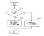
図10は、ズーム倍率を変更する処理のフローチャートである。 FIG. 10 is a flowchart of processing for changing the zoom magnification.
まず、コントローラ210は、ズーム指示により、ズーム倍率が増加するか(望遠)、低下するか(広角)を判定する(S151)。
First, the
ズーム倍率が低下する場合(S151でNo)、コントローラ210は、通常速度(第1の速度)でズーム倍率を変更する(S153)。
When the zoom magnification decreases (No in S151), the
図11Aは、この場合の安全性評価値とズーム速度との関係を示す図である。図11Aに示すように、広角側へズームする場合は、安全性評価値に関わらず同じ速度V1でズーム動作が行なわれる。 FIG. 11A is a diagram showing the relationship between the safety evaluation value and the zoom speed in this case. As shown in FIG. 11A, when zooming to the wide-angle side, the zoom operation is performed at the same speed V1 regardless of the safety evaluation value.
一方、ズーム倍率が増加する場合(S151でYes)、コントローラ210は、安全性評価値に基づき、ズーム速度を決定し、決定したズーム速度でズーム倍率を変更する(S152)。なお、この安全性評価値に基づきズーム倍率を変更する方法として、例えば、図4に示すS123〜S126を用いることができる。図11Bは、この場合の安全性評価値とズーム速度との関係を示す図である。図11Bに示すように、安全性評価値がT1よりも大きい場合には、第1の速度V1でズーム動作が行われ、安全性評価値がT1よりも小さい場合には、第1の速度V1より遅い第2の速度V2でズーム動作が行われる。なお、S153のズーム速度V1と、S152の安全性評価値が大きい場合のズーム速度V1とは異なってもよい。
On the other hand, when the zoom magnification increases (Yes in S151), the
ここで、一般に高倍率ズームになるほど視差が大きくなり、危険な状態になる可能性が高くなる。よって、コントローラ210は、望遠側へのズーム時には危険な視差の状態になる可能性がより高まるためズーム速度を低下させる。一方広角側へのズーム時には、仮に現在の状態が危険な視差の状態であっても、ズームすることによりズーム倍率が低下し、安全な視差状態へ移行する可能性が高まる。よって、コントローラ210は、ズーム速度を変更しない。
Here, in general, the higher the zoom ratio, the greater the parallax, and the higher the possibility of entering a dangerous state. Therefore, the
なお、ここでは、図11Bに示すように2段階でズーム速度が変更される例を示したが、図12Aに示すように3段階でズーム速度が変更されてもよい。さらに、4段階以上でズーム速度が変更されてもよい。 Although an example in which the zoom speed is changed in two steps as shown in FIG. 11B is shown here, the zoom speed may be changed in three steps as shown in FIG. 12A. Further, the zoom speed may be changed in four steps or more.
また、図12Bに示すように、ズーム速度は、安全性評価値に応じて連続的に変化してもよい。なお、図12Bでは、ズーム速度が直線的に減少しているが、ズーム速度は、曲線的に減少してもよい。 Further, as shown in FIG. 12B, the zoom speed may continuously change in accordance with the safety evaluation value. In FIG. 12B, the zoom speed decreases linearly, but the zoom speed may decrease curvilinearly.
また、安全性評価値に基づきズーム倍率を変更する方法として、以下の方法を用いてもよい。 Further, as a method of changing the zoom magnification based on the safety evaluation value, the following method may be used.
図13は、この場合の安全性評価値に基づきズーム倍率を変更する処理のフローチャートである。 FIG. 13 is a flowchart of processing for changing the zoom magnification based on the safety evaluation value in this case.
コントローラ210は、安全性評価値が第1閾値以上であるか、第1閾値未満かつ第2閾値以上であるか、第2閾値未満であるかを判定する(S161及びS162)。
The
安全性評価値が第1閾値以上である場合(S161でYes)、コントローラ210は、通常速度でズーム倍率を変更する(S163)。
When the safety evaluation value is equal to or greater than the first threshold (Yes in S161), the
安全性評価値が第1閾値未満、かつ、第2閾値以上である場合(S161でNo、かつ、S162でYes)、コントローラ210は、低速度でズーム倍率を変更する(S164)。なお、この場合において、コントローラ210は、安全性評価値に応じてズーム速度を決定し、決定したズーム速度でズーム倍率を変更してもよい。
If the safety evaluation value is less than the first threshold and greater than or equal to the second threshold (No in S161 and Yes in S162), the
安全性評価値が第2閾値未満である場合(S161でNo、かつ、S162でNo)、コントローラ210は、ズーム倍率の変更を禁止し、ズーム倍率の変更を行わない(S165)。
When the safety evaluation value is less than the second threshold (No in S161 and No in S162), the
図14Aは、この場合の安全性評価値とズーム速度との関係を示す図である。図14Aに示すように、安全性評価値が高い間は、ズーム速度は第1の速度V1である。安全性評価値が第1閾値T1より小さくなると、ズーム速度は第2の速度V2に設定される。さらに、安全性評価値が第2閾値T2より小さくなると、ズーム速度が0に設定される。すなわち、コントローラ210は、ズーム動作を停止させる。
FIG. 14A is a diagram showing the relationship between the safety evaluation value and the zoom speed in this case. As shown in FIG. 14A, while the safety evaluation value is high, the zoom speed is the first speed V1. When the safety evaluation value becomes smaller than the first threshold value T1, the zoom speed is set to the second speed V2. Further, when the safety evaluation value becomes smaller than the second threshold value T2, the zoom speed is set to zero. That is, the
なお、図14Bに示すように、安全性評価値がT1〜T2の場合に、安全性評価値に従って徐々にズーム速度が変更されてもよい。 As illustrated in FIG. 14B, when the safety evaluation value is T1 to T2, the zoom speed may be gradually changed according to the safety evaluation value.
また、図14A及び図14Bに示す例では、安全性評価値が0〜T2の範囲、T2〜T1の範囲、T1〜1の範囲の3つの範囲で、それぞれズーム速度の制御が切り替えられるが、この限りではなく、2つの範囲又は4つの範囲で速度の制御を切り替えてもよい。 In the example shown in FIGS. 14A and 14B, the zoom speed control is switched in each of three ranges, ie, a safety evaluation value range of 0 to T2, a range of T2 to T1, and a range of T1 to 1. Not limited to this, the speed control may be switched in two ranges or four ranges.
また、上記説明では、ズーム倍率の変更方向(望遠側、広角側)であるズーム方向を判定した後に、安全性評価を用いたズーム速度の制御を行っているが、ズーム方向に応じて、安全性評価値を決定してもよい。例えば、コントローラ210は、広角側へズームする場合に、視差量によらず、安全性評価値を1に設定してもよい。このような方法でも、上記と同様の処理を実現できる。
In the above description, the zoom speed is controlled using the safety evaluation after determining the zoom direction that is the zoom magnification changing direction (telephoto side, wide angle side). A sex evaluation value may be determined. For example, the
また、ズーム速度の決定方式の適用を、広角側へのズームか望遠側へのズームかで切り替えるのではなく、安全性評価値の時間変化に基づいて切り替えるようにしてもよい。 Further, the application of the zoom speed determination method may be switched based on the time change of the safety evaluation value, instead of switching between zooming toward the wide angle side and zooming toward the telephoto side.
図15は、この場合のズーム速度の決定処理のフローチャートである。 FIG. 15 is a flowchart of the zoom speed determination process in this case.
まず、コントローラ210は、安全性評価値が減少したか否かを判定する(S171)。具体的には、コントローラ210は、安全性評価値を所定の時間間隔でサンプリングして保存しておく。そして、コントローラ210は、直近のN個の安全性評価値が減少傾向にあるか否かを判定する。
First, the
安全性評価値が変化無しか増加傾向(視差が安全になる傾向)であれば(S171でNo)、コントローラ210は、現在の安全性評価値に関わりなく一定速度(例えば、通常速度)でズーム倍率を変更する(S173)。一方、安全性評価値が減少傾向(視差が危険な状態になりつつある)であれば(S171でYes)、コントローラ210は、安全性評価値に基づく速度でズーム倍率を変更する(S172)。この処理は、例えば、図10に示すS152と同様である。これにより、コントローラ210は、画像の視差の変化に基づき、より直接的にズーム速度を制御できるので、視差の安全性がさらに向上する。
If the safety evaluation value does not change or tends to increase (the disparity tends to be safe) (No in S171), the
なお、図16に示すように、安全性評価値が減少傾向(視差が危険な状態になりつつある)である場合(S171でYes)に、コントローラ210は、低速度(第2の速度)でズーム倍率を変更してもよい(S174)。
In addition, as shown in FIG. 16, when the safety evaluation value is decreasing (parallax is becoming a dangerous state) (Yes in S171), the
また、上記説明では、デジタルカメラ100は、2つの光学系110A及び110Bを備えるが、一つの光学系のみを備える単眼の3Dカメラにも本開示を適用できる。
In the above description, the
また、上記説明では、デジタルカメラ100が、視差量から安全性評価値を算出し、安全性評価値に基づき、ズーム速度を制御する例を述べたが、安全性評価値を算出せず、視差量に基づき、ズーム速度を変更しても同様の処理を実現できる。
In the above description, an example has been described in which the
また、上記説明では、通常のズーム速度が一定である場合を例に説明したが、通常のズーム速度(第1の速度)は、ユーザの操作に応じて変更可能であってもよい。この場合、上記低速度(第2の速度)は、ユーザの操作により指定された速度よりも遅い速度であればよい。 In the above description, the case where the normal zoom speed is constant has been described as an example. However, the normal zoom speed (first speed) may be changed according to a user operation. In this case, the low speed (second speed) may be any speed that is slower than the speed specified by the user's operation.
[1−3.効果等]
以上のように、本実施の形態において、デジタルカメラ100は、被写体の光学像を形成する光学系110A及び110Bと、当該光学像から、立体視用の映像を構成する第1視点画像151A及び第2視点画像151Bを生成するCCDイメージセンサ150A及び150Bと、光学系110A及び110Bのズーム動作を制御するコントローラ210とを備える。コントローラ210は、上記2枚の画像における視差量に基づいて、第1の速度で、光学系110A及び110Bのズーム動作を実行する第1動作と、第1の速度よりも遅い第2の速度で、光学系110A及び110Bのズーム動作を実行する第2動作とを選択的に切り替えて実行する。
[1-3. Effect]
As described above, in the present embodiment, the
これにより、デジタルカメラ100は、ズーム動作により、3D映像として危険な映像が撮影されることを抑制できる。
Thereby, the
また、コントローラ210は、上記視差量に基づいて立体視用の映像が視聴された際の安全性を示す安全性評価値を算出し、当該安全性評価値が第1の値よりも大きい場合は上記第1動作を実行し、安全性評価値が第1の値よりも小さい場合、上記第2動作を実行する。
Further, the
これにより、デジタルカメラ100は、立体視用の映像が視聴された際の安全性に基づいて、ズーム動作を選択的に着替えることができるので、ズーム動作により、3D映像として危険な映像が撮影されることを抑制できる。
Accordingly, the
また、コントローラ210は、上記第2の速度を、安全性評価値が小さくなるにつれて遅くなるように変更する。
Further, the
これにより、立体視用の映像の視聴上の安全性が低い場合に、より安全性が低くなる恐れのあるズーム動作を抑制すると共に、そのような状態であることを撮影者に知らせることができる。 Thereby, when viewing safety of the stereoscopic image is low, it is possible to suppress a zoom operation that may be less secure and to notify the photographer that such a state is present. .
また、コントローラ210は、安全性評価値が、第1の値より小さく、かつ第1の値より小さい第2の値よりも大きい場合、上記第2の動作を実行し、安全性評価値が第2の値より小さい場合、ズーム動作を禁止する。
Further, when the safety evaluation value is smaller than the first value and larger than the second value smaller than the first value, the
これにより、立体視用の映像の視聴上の安全性が低い場合に、ズーム動作を行なうことでより危険な状態になることがないように、ズーム動作をさせないようにすることができる。またそのことによって、撮影者に危険な映像が撮影されていることを知らせることができる。 Thereby, when the viewing safety of the stereoscopic video is low, it is possible to prevent the zoom operation from being performed so that the zoom operation does not cause a more dangerous state. This also allows the photographer to be notified that a dangerous video is being shot.
また、コントローラ210は、光学系110A及び110Bのズーム倍率を増加させる場合、上記第1動作と上記第2動作とを選択的に切り替えて実行し、光学系110A及び110Bのズーム倍率を減少させる場合、上記第1動作を実行する。
When the
これにより、立体視用の映像の視聴上の安全性がより低くなる恐れのある、拡大側へのズームを行なう場合にのみ、ズーム動作を選択的に切り替え、安全性が低くなる恐れのない縮小側へのズーム時には、ズーム動作を切り替えないようにすることができる。これにより、コントローラ210は、ズーム動作による安全性の変化に基づいた、ズーム動作の切り替えを実現できる。
As a result, the zoom operation is selectively switched only when zooming to the enlargement side, which may reduce the safety of viewing stereoscopic images, and the reduction without the risk of lowering the safety. When zooming to the side, it is possible not to switch the zoom operation. Thereby, the
また、コントローラ210は、上記視差量の時間変化に基づいて、上記第1動作と上記第2動作とを選択的に切り替えて実行する。
Further, the
これにより、例えば、立体視用の映像の視聴上の安全性が低くなる場合に、ズーム動作を抑制すると共に、そのような状態であることを撮影者に知らせることができる。 Thereby, for example, when the safety in viewing a stereoscopic video is lowered, the zoom operation can be suppressed and the photographer can be informed of such a state.
また、コントローラ210は、上記時間変化が、安全性が増加する傾向である場合、上記第1動作を実行し、上記安全性が減少する傾向である場合、上記第2動作を実行する。
The
これにより、立体視用の映像の視聴上の安全性が低くなる場合に、ズーム動作を抑制すると共に、そのような状態であることを撮影者に知らせることができる。 Thereby, when the viewing safety of the stereoscopic video is lowered, it is possible to suppress the zoom operation and to notify the photographer of such a state.
また、コントローラ210は、光学系110A及び110Bのズーム倍率が増加する場合、立体視用の映像の一部を拡大した映像における視差量に基づいて、上記第1動作と上記第2動作とを選択的に切り替えて実行する。
Further, when the zoom magnification of the
これにより、コントローラ210は、ズーム倍率を変更した後の映像における視差量に基づいて、ズーム動作の速度を制御できる。
Thereby, the
また、コントローラ210は、光学系110A及び110Bのズーム倍率が減少する場合、立体視用の映像より広い範囲を撮影した画像を縮小した画像における視差量に基づいて、上記第1動作と上記第2動作とを選択的に切り替えて実行する。
In addition, when the zoom magnifications of the
これにより、コントローラ210は、ズーム倍率を変更した後の映像における視差量に基づいて、ズーム動作の速度を制御できる。
Thereby, the
また、コントローラ210は、立体視用の映像が有する複数の視差量のうち最大の視差量と最小の視差量との差である視差レンジを算出し、視差レンジが第3の値より小さい場合は上記第1動作を実行し、視差レンジが第3の値より大きい場合、上記第2動作を実行する。
Further, the
これにより、デジタルカメラ100は、ズーム動作により、3D映像として危険な映像が撮影されることを抑制できる。
Thereby, the
また、コントローラ210は、立体視用の映像が有する複数の視差量のうち、予め定められた範囲に含まれる視差量の数をカウントし、カウントされた視差量の数が第4の値より多い場合は上記第1動作を実行し、カウントされた視差量の数が第4の値より少ない場合、上記第2動作を実行する。
Further, the
これにより、デジタルカメラ100は、画像全体の安全性を加味して、ズーム動作の速度を制御できる。
Thereby, the
[2.その他の実施形態]
実施の形態では、撮像部(イメージセンサ)の一例としてCCDイメージセンサ150A及び150Bを説明した。撮像部は、被写体像を撮像して画像データを生成するものであればよい。したがって、撮像部は、CCDイメージセンサ150A及び150Bに限定されない。ただし、撮像部としてCCDイメージセンサ150A及び150Bを用いれば、安価に撮像部を入手可能である。また、CMOSイメージセンサを撮像部として用いてもよい。撮像部としてCMOSイメージセンサを用いれば、消費電力の抑制に有効である。
[2. Other Embodiments]
In the embodiment, the
実施の形態では、制御部の一例としてコントローラ210を説明した。制御部は、デジタルカメラを制御するものであれば、物理的にどのように構成してもよい。なお、制御部に、プログラム可能なマイクロコンピュータ170を用いれば、プログラムの変更により処理内容を変更できるので、制御部の設計の自由度を高めることができる。また、制御部は、ハードロジックで実現してもよい。制御部をハードロジックで実現すれば、処理速度の向上に有効である。制御部は、1つの素子で構成してもよいし、物理的に複数の素子で構成してもよい。複数の素子で構成する場合、請求の範囲に記載の各制御を別の素子で実現してもよい。この場合、それらの複数の素子で一つの制御部を構成すると考えることができる。また、制御部と別の機能を有する部材とを1つの素子で構成してもよい。
In the embodiment, the
上記実施の形態で説明したデジタルカメラにおいて、各ブロックは、LSIなどの半導体装置により個別に1チップ化されても良いし、一部又は全部を含むように1チップ化されても良い。 In the digital camera described in the above embodiment, each block may be individually made into one chip by a semiconductor device such as an LSI, or may be made into one chip so as to include a part or the whole.
なお、ここでは、LSIとしたが、集積度の違いにより、IC、システムLSI、スーパーLSI、ウルトラLSIと呼称されることもある。 Here, although LSI is used, it may be called IC, system LSI, super LSI, or ultra LSI depending on the degree of integration.
また、集積回路化の手法はLSIに限るものではなく、専用回路又は汎用プロセサで実現してもよい。LSI製造後に、プログラムすることが可能なFPGA(Field Programmable Gate Array)や、LSI内部の回路セルの接続や設定を再構成可能なリコンフィギュラブル・プロセッサを利用しても良い。 Further, the method of circuit integration is not limited to LSI, and implementation with a dedicated circuit or a general-purpose processor is also possible. An FPGA (Field Programmable Gate Array) that can be programmed after manufacturing the LSI, or a reconfigurable processor that can reconfigure the connection and setting of circuit cells inside the LSI may be used.
さらには、半導体技術の進歩又は派生する別技術によりLSIに置き換わる集積回路化の技術が登場すれば、当然、その技術を用いて機能ブロックの集積化を行ってもよい。バイオ技術の適用等が可能性としてあり得る。 Further, if integrated circuit technology comes out to replace LSI's as a result of the advancement of semiconductor technology or a derivative other technology, it is naturally also possible to carry out function block integration using this technology. Biotechnology can be applied as a possibility.
また、上記実施の形態の各処理をハードウェアにより実現してもよいし、ソフトウェアにより実現してもよい。さらに、ソフトウェア及びハードウェアの混在処理により実現しても良い。なお、上記実施の形態に係るデジタルカメラをハードウェアにより実現する場合、各処理を行うためのタイミング調整を行う必要があるのは言うまでもない。上記実施の形態においては、説明便宜のため、実際のハードウェア設計で生じる各種信号のタイミング調整の詳細については省略している。 Moreover, each process of the said embodiment may be implement | achieved by hardware, and may be implement | achieved by software. Further, it may be realized by mixed processing of software and hardware. Needless to say, when the digital camera according to the above-described embodiment is realized by hardware, it is necessary to adjust timing for performing each process. In the above embodiment, for convenience of explanation, details of timing adjustment of various signals generated in actual hardware design are omitted.
また、上記実施の形態における処理方法の実行順序は、必ずしも、上記実施の形態の記載に制限されるものではなく、発明の要旨を逸脱しない範囲で、実行順序を入れ替えることができるものである。 Moreover, the execution order of the processing method in the said embodiment is not necessarily restricted to description of the said embodiment, The execution order can be changed in the range which does not deviate from the summary of invention.
また、ブロック図における機能ブロックの分割は一例であり、複数の機能ブロックを一つの機能ブロックとして実現したり、一つの機能ブロックを複数に分割したり、一部の機能を他の機能ブロックに移してもよい。また、類似する機能を有する複数の機能ブロックの機能を単一のハードウェア又はソフトウェアが並列又は時分割に処理してもよい。 In addition, division of functional blocks in the block diagram is an example, and a plurality of functional blocks can be realized as one functional block, a single functional block can be divided into a plurality of functions, or some functions can be transferred to other functional blocks May be. In addition, functions of a plurality of functional blocks having similar functions may be processed in parallel or time-division by a single hardware or software.
また、上記実施の形態、及びその変形例に係る立体映像処理装置の機能のうち少なくとも一部を組み合わせてもよい。 Moreover, you may combine at least one part among the functions of the stereoscopic video processing apparatus which concerns on the said embodiment and its modification.
以上のように、本開示における技術の例示として、実施の形態を説明した。そのために、添付図面および詳細な説明を提供した。 As described above, the embodiments have been described as examples of the technology in the present disclosure. For this purpose, the accompanying drawings and detailed description are provided.
したがって、添付図面および詳細な説明に記載された構成要素の中には、課題解決のために必須な構成要素だけでなく、上記技術を例示するために、課題解決のためには必須でない構成要素も含まれ得る。そのため、それらの必須ではない構成要素が添付図面や詳細な説明に記載されていることをもって、直ちに、それらの必須ではない構成要素が必須であるとの認定をするべきではない。 Accordingly, among the components described in the accompanying drawings and the detailed description, not only the components essential for solving the problem, but also the components not essential for solving the problem in order to illustrate the above technique. May also be included. Therefore, it should not be immediately recognized that these non-essential components are essential as those non-essential components are described in the accompanying drawings and detailed description.
また、上述の実施の形態は、本開示における技術を例示するためのものであるから、請求の範囲またはその均等の範囲において種々の変更、置き換え、付加、省略などを行うことができる。 Moreover, since the above-mentioned embodiment is for demonstrating the technique in this indication, a various change, substitution, addition, abbreviation, etc. can be performed in a claim or its equivalent range.
本開示は、ズーム動作により、3D映像として危険な映像が撮影されることを抑制できる立体映像撮影装置に適用可能である。具体的には、デジタルスチルカメラ、デジタルビデオカメラ、放送用カメラ、カメラ機能付き携帯電話機、及び、スマートフォンなどに、本開示は適用可能である。 The present disclosure can be applied to a stereoscopic video imaging apparatus that can prevent dangerous video from being captured as 3D video by a zoom operation. Specifically, the present disclosure is applicable to a digital still camera, a digital video camera, a broadcasting camera, a mobile phone with a camera function, a smartphone, and the like.
100 デジタルカメラ
110A、110B 光学系
111A、111B ズームレンズ
112A、112B OIS
113A、113B フォーカスレンズ
120 ズームモータ
130 OISアクチュエータ
140 フォーカスモータ
150A、150B CCDイメージセンサ
151A 第1視点画像
151B 第2視点画像
160 映像処理部
200 メモリ
210 コントローラ
220 ジャイロセンサ
230 カードスロット
240 メモリカード
250 操作部材
260 ズームレバー
270 液晶モニタ
280 内部メモリ
290 モード設定ボタン
401、405 記録用画像
402、404 画像
403、406 視差検出用画像
100
113A,
Claims (12)
被写体の光学像を形成する光学系と、
前記光学像から、前記立体視用の映像を構成する第1及び第2視点画像を生成するイメージセンサと、
前記光学系のズーム動作を制御する制御部とを備え、
前記制御部は、前記第1及び第2視点画像における視差量に基づいて、第1の速度で前記ズーム動作を実行する第1動作と、前記第1の速度よりも遅い第2の速度で前記ズーム動作を実行する第2動作とを選択的に切り替えて実行する
立体映像撮影装置。 A stereoscopic image capturing device for capturing a stereoscopic image,
An optical system for forming an optical image of a subject;
An image sensor for generating first and second viewpoint images constituting the stereoscopic video image from the optical image;
A control unit for controlling the zoom operation of the optical system,
The control unit is configured to execute a zoom operation at a first speed based on a parallax amount in the first and second viewpoint images, and a second speed slower than the first speed. A stereoscopic video imaging apparatus that selectively switches and executes a second operation for executing a zoom operation.
請求項1に記載の立体映像撮影装置。 The control unit calculates a safety evaluation value indicating safety when the stereoscopic video is viewed based on the parallax amount, and when the safety evaluation value is larger than a first value The stereoscopic video imaging device according to claim 1, wherein the first operation is executed, and the second operation is executed when the safety evaluation value is smaller than the first value.
請求項2に記載の立体映像撮影装置。 The stereoscopic video imaging apparatus according to claim 2, wherein the control unit changes the second speed so as to become slower as the safety evaluation value becomes smaller.
前記安全性評価値が、前記第1の値より小さく、かつ前記第1の値より小さい第2の値よりも大きい場合、前記第2の動作を実行し、
前記安全性評価値が前記第2の値より小さい場合、前記ズーム動作を禁止する
請求項2又は3に記載の立体映像撮影装置。 The controller is
When the safety evaluation value is smaller than the first value and larger than a second value smaller than the first value, the second operation is performed;
The stereoscopic image capturing apparatus according to claim 2, wherein the zoom operation is prohibited when the safety evaluation value is smaller than the second value.
前記光学系のズーム倍率を増加させる場合、前記視差量に基づいて前記第1動作と前記第2動作とを選択的に切り替えて実行し、
前記光学系のズーム倍率を減少させる場合、前記第1動作を実行する
請求項1に記載の立体映像撮影装置。 The controller is
When increasing the zoom magnification of the optical system, selectively executing the first operation and the second operation based on the parallax amount,
The stereoscopic image capturing apparatus according to claim 1, wherein the first operation is performed when the zoom magnification of the optical system is decreased.
請求項1に記載の立体映像撮影装置。 The stereoscopic video imaging apparatus according to claim 1, wherein the control unit selectively switches between the first operation and the second operation based on a temporal change in the parallax amount.
請求項6に記載の立体映像撮影装置。 The control unit performs the first operation when the temporal change tends to increase safety when the stereoscopic video is viewed, and the safety tends to decrease. The stereoscopic image capturing apparatus according to claim 6, wherein the second operation is executed.
請求項1に記載の立体映像撮影装置。 When the zoom magnification of the optical system is increased, the control unit selectively selects the first operation and the second operation based on a parallax amount in an image obtained by enlarging a part of the image for stereoscopic viewing. The stereoscopic image capturing apparatus according to claim 1, wherein the stereoscopic image capturing apparatus is executed by switching.
請求項1に記載の立体映像撮影装置。 When the zoom magnification of the optical system decreases, the control unit performs the first operation and the second operation based on a parallax amount in an image obtained by reducing an image obtained by capturing a wider range than the stereoscopic image. The stereoscopic image capturing apparatus according to claim 1, wherein the three-dimensional image capturing device is selectively switched and executed.
前記立体視用の映像が有する複数の視差量のうち最大の視差量と最小の視差量との差である視差レンジを算出し、
前記視差レンジが第3の値より小さい場合は前記第1動作を実行し、前記視差レンジが前記第3の値より大きい場合、前記第2動作を実行する
請求項1に記載の立体映像撮影装置。 The controller is
Calculating a parallax range which is a difference between a maximum parallax amount and a minimum parallax amount among a plurality of parallax amounts included in the stereoscopic video;
The stereoscopic image capturing apparatus according to claim 1, wherein when the parallax range is smaller than a third value, the first operation is performed, and when the parallax range is larger than the third value, the second operation is performed. .
前記立体視用の映像が有する複数の視差量のうち、予め定められた範囲に含まれる視差量の数をカウントし、
カウントされた前記数が第4の値より多い場合は前記第1動作を実行し、前記数が前記第4の値より少ない場合、前記第2動作を実行する
請求項1に記載の立体映像撮影装置。 The controller is
Counting the number of parallax amounts included in a predetermined range among a plurality of parallax amounts of the stereoscopic video,
The stereoscopic video shooting according to claim 1, wherein when the counted number is larger than a fourth value, the first operation is performed, and when the number is smaller than the fourth value, the second operation is performed. apparatus.
前記光学像から、前記立体視用の映像を構成する第1及び第2視点画像を生成するイメージセンサと、
前記光学系のズーム動作を制御する制御部とを備える立体映像撮影装置におけるズーム動作の制御方法であって、
前記第1及び第2視点画像における視差量に基づいて、第1の速度で前記ズーム動作を実行する第1動作と、前記第1の速度よりも遅い第2の速度で前記ズーム動作を実行する第2動作とを選択的に切り替えて実行する、
ズーム動作の制御方法。 An optical system for forming an optical image of a subject;
An image sensor for generating first and second viewpoint images constituting the stereoscopic video image from the optical image;
A control method of a zoom operation in a stereoscopic video imaging apparatus comprising a control unit for controlling the zoom operation of the optical system,
Based on the amount of parallax in the first and second viewpoint images, the first operation for executing the zoom operation at a first speed and the zoom operation at a second speed slower than the first speed. Selectively switching to the second operation and executing.
Control method of zoom operation.
Priority Applications (1)
| Application Number | Priority Date | Filing Date | Title |
|---|---|---|---|
| JP2013502314A JP5221827B1 (en) | 2011-11-29 | 2012-11-06 | Stereoscopic image capturing apparatus and zoom operation control method |
Applications Claiming Priority (4)
| Application Number | Priority Date | Filing Date | Title |
|---|---|---|---|
| JP2011259942 | 2011-11-29 | ||
| JP2011259942 | 2011-11-29 | ||
| PCT/JP2012/007093 WO2013080445A1 (en) | 2011-11-29 | 2012-11-06 | Three-dimensional imaging device and control method for zoom operation |
| JP2013502314A JP5221827B1 (en) | 2011-11-29 | 2012-11-06 | Stereoscopic image capturing apparatus and zoom operation control method |
Publications (2)
| Publication Number | Publication Date |
|---|---|
| JP5221827B1 true JP5221827B1 (en) | 2013-06-26 |
| JPWO2013080445A1 JPWO2013080445A1 (en) | 2015-04-27 |
Family
ID=48534948
Family Applications (1)
| Application Number | Title | Priority Date | Filing Date |
|---|---|---|---|
| JP2013502314A Expired - Fee Related JP5221827B1 (en) | 2011-11-29 | 2012-11-06 | Stereoscopic image capturing apparatus and zoom operation control method |
Country Status (2)
| Country | Link |
|---|---|
| JP (1) | JP5221827B1 (en) |
| WO (1) | WO2013080445A1 (en) |
Cited By (1)
| Publication number | Priority date | Publication date | Assignee | Title |
|---|---|---|---|---|
| CN104677306A (en) * | 2015-03-13 | 2015-06-03 | 厦门大学 | Visual detection device of sheet metal |
Citations (5)
| Publication number | Priority date | Publication date | Assignee | Title |
|---|---|---|---|---|
| JPH08317429A (en) * | 1995-05-23 | 1996-11-29 | Matsushita Electric Ind Co Ltd | Stereoscopic electronic zoom device and stereoscopic picture quality controller |
| JPH0937302A (en) * | 1995-07-18 | 1997-02-07 | Olympus Optical Co Ltd | Stereoscopic image pickup device |
| JP2010081010A (en) * | 2008-09-24 | 2010-04-08 | Fujifilm Corp | Three-dimensional imaging device, method and program |
| JP2010109785A (en) * | 2008-10-31 | 2010-05-13 | Fujifilm Corp | Three-dimensional imaging apparatus and method, and program |
| JP2010226320A (en) * | 2009-03-23 | 2010-10-07 | Fujifilm Corp | Imaging apparatus |
-
2012
- 2012-11-06 WO PCT/JP2012/007093 patent/WO2013080445A1/en active Application Filing
- 2012-11-06 JP JP2013502314A patent/JP5221827B1/en not_active Expired - Fee Related
Patent Citations (5)
| Publication number | Priority date | Publication date | Assignee | Title |
|---|---|---|---|---|
| JPH08317429A (en) * | 1995-05-23 | 1996-11-29 | Matsushita Electric Ind Co Ltd | Stereoscopic electronic zoom device and stereoscopic picture quality controller |
| JPH0937302A (en) * | 1995-07-18 | 1997-02-07 | Olympus Optical Co Ltd | Stereoscopic image pickup device |
| JP2010081010A (en) * | 2008-09-24 | 2010-04-08 | Fujifilm Corp | Three-dimensional imaging device, method and program |
| JP2010109785A (en) * | 2008-10-31 | 2010-05-13 | Fujifilm Corp | Three-dimensional imaging apparatus and method, and program |
| JP2010226320A (en) * | 2009-03-23 | 2010-10-07 | Fujifilm Corp | Imaging apparatus |
Cited By (1)
| Publication number | Priority date | Publication date | Assignee | Title |
|---|---|---|---|---|
| CN104677306A (en) * | 2015-03-13 | 2015-06-03 | 厦门大学 | Visual detection device of sheet metal |
Also Published As
| Publication number | Publication date |
|---|---|
| WO2013080445A1 (en) | 2013-06-06 |
| JPWO2013080445A1 (en) | 2015-04-27 |
Similar Documents
| Publication | Publication Date | Title |
|---|---|---|
| JP5789793B2 (en) | Three-dimensional imaging device, lens control device, and program | |
| JP5640143B2 (en) | Imaging apparatus and imaging method | |
| US8878907B2 (en) | Monocular stereoscopic imaging device | |
| JP5469258B2 (en) | Imaging apparatus and imaging method | |
| JP5374641B2 (en) | 3D video recording apparatus and 3D video signal processing apparatus | |
| JP6432038B2 (en) | Imaging device | |
| US20130050536A1 (en) | Compound-eye imaging device | |
| JP2013046292A (en) | Compound-eye image pickup device | |
| US20160275657A1 (en) | Imaging apparatus, image processing apparatus and method of processing image | |
| US9202315B2 (en) | Three-dimensional video image processing device and three-dimensional video image processing method | |
| US9602799B2 (en) | Device, method, and computer program for three-dimensional video processing | |
| WO2013069279A1 (en) | Image capturing device | |
| JP5221827B1 (en) | Stereoscopic image capturing apparatus and zoom operation control method | |
| JP2013062557A (en) | Digital imaging apparatus and 3d imaging method | |
| US20130076867A1 (en) | Imaging apparatus | |
| JP2012220603A (en) | Three-dimensional video signal photography device | |
| JP5325336B2 (en) | 3D image processing apparatus, method, and program | |
| JP5988213B2 (en) | Arithmetic processing unit | |
| JP2012054919A (en) | Imaging device | |
| JP2012151538A (en) | Three-dimensional imaging apparatus | |
| JP2013162489A (en) | 3d image pickup device | |
| JP2015158627A (en) | Imaging device and control method of the same | |
| JP2015156552A (en) | Imaging apparatus, control method of the same, program, and storage medium | |
| JP2013145372A (en) | Imaging apparatus | |
| JP2012209896A (en) | Image processor, imaging apparatus and program |
Legal Events
| Date | Code | Title | Description |
|---|---|---|---|
| TRDD | Decision of grant or rejection written | ||
| A01 | Written decision to grant a patent or to grant a registration (utility model) |
Free format text: JAPANESE INTERMEDIATE CODE: A01 Effective date: 20130305 |
|
| FPAY | Renewal fee payment (event date is renewal date of database) |
Free format text: PAYMENT UNTIL: 20160315 Year of fee payment: 3 |
|
| R150 | Certificate of patent or registration of utility model |
Free format text: JAPANESE INTERMEDIATE CODE: R150 |
|
| LAPS | Cancellation because of no payment of annual fees |