JP5221018B2 - Power receiving patch panel - Google Patents
Power receiving patch panel Download PDFInfo
- Publication number
- JP5221018B2 JP5221018B2 JP2006265275A JP2006265275A JP5221018B2 JP 5221018 B2 JP5221018 B2 JP 5221018B2 JP 2006265275 A JP2006265275 A JP 2006265275A JP 2006265275 A JP2006265275 A JP 2006265275A JP 5221018 B2 JP5221018 B2 JP 5221018B2
- Authority
- JP
- Japan
- Prior art keywords
- power
- port
- circuit
- patch panel
- current
- Prior art date
- Legal status (The legal status is an assumption and is not a legal conclusion. Google has not performed a legal analysis and makes no representation as to the accuracy of the status listed.)
- Expired - Fee Related
Links
Images


Classifications
-
- H—ELECTRICITY
- H04—ELECTRIC COMMUNICATION TECHNIQUE
- H04L—TRANSMISSION OF DIGITAL INFORMATION, e.g. TELEGRAPHIC COMMUNICATION
- H04L12/00—Data switching networks
- H04L12/66—Arrangements for connecting between networks having differing types of switching systems, e.g. gateways
-
- H—ELECTRICITY
- H04—ELECTRIC COMMUNICATION TECHNIQUE
- H04L—TRANSMISSION OF DIGITAL INFORMATION, e.g. TELEGRAPHIC COMMUNICATION
- H04L41/00—Arrangements for maintenance, administration or management of data switching networks, e.g. of packet switching networks
- H04L41/08—Configuration management of networks or network elements
- H04L41/0803—Configuration setting
-
- H—ELECTRICITY
- H04—ELECTRIC COMMUNICATION TECHNIQUE
- H04L—TRANSMISSION OF DIGITAL INFORMATION, e.g. TELEGRAPHIC COMMUNICATION
- H04L43/00—Arrangements for monitoring or testing data switching networks
- H04L43/08—Monitoring or testing based on specific metrics, e.g. QoS, energy consumption or environmental parameters
- H04L43/0805—Monitoring or testing based on specific metrics, e.g. QoS, energy consumption or environmental parameters by checking availability
- H04L43/0811—Monitoring or testing based on specific metrics, e.g. QoS, energy consumption or environmental parameters by checking availability by checking connectivity
-
- H—ELECTRICITY
- H04—ELECTRIC COMMUNICATION TECHNIQUE
- H04L—TRANSMISSION OF DIGITAL INFORMATION, e.g. TELEGRAPHIC COMMUNICATION
- H04L43/00—Arrangements for monitoring or testing data switching networks
- H04L43/08—Monitoring or testing based on specific metrics, e.g. QoS, energy consumption or environmental parameters
- H04L43/0805—Monitoring or testing based on specific metrics, e.g. QoS, energy consumption or environmental parameters by checking availability
- H04L43/0817—Monitoring or testing based on specific metrics, e.g. QoS, energy consumption or environmental parameters by checking availability by checking functioning
-
- H—ELECTRICITY
- H04—ELECTRIC COMMUNICATION TECHNIQUE
- H04M—TELEPHONIC COMMUNICATION
- H04M3/00—Automatic or semi-automatic exchanges
- H04M3/22—Arrangements for supervision, monitoring or testing
- H04M3/2254—Arrangements for supervision, monitoring or testing in networks
-
- H—ELECTRICITY
- H04—ELECTRIC COMMUNICATION TECHNIQUE
- H04Q—SELECTING
- H04Q1/00—Details of selecting apparatus or arrangements
- H04Q1/02—Constructional details
- H04Q1/03—Power distribution arrangements
-
- H—ELECTRICITY
- H04—ELECTRIC COMMUNICATION TECHNIQUE
- H04Q—SELECTING
- H04Q1/00—Details of selecting apparatus or arrangements
- H04Q1/02—Constructional details
- H04Q1/13—Patch panels for monitoring, interconnecting or testing circuits, e.g. patch bay, patch field or jack field; Patching modules
- H04Q1/135—Patch panels for monitoring, interconnecting or testing circuits, e.g. patch bay, patch field or jack field; Patching modules characterized by patch cord details
- H04Q1/136—Patch panels for monitoring, interconnecting or testing circuits, e.g. patch bay, patch field or jack field; Patching modules characterized by patch cord details having patch field management or physical layer management arrangements
-
- H—ELECTRICITY
- H04—ELECTRIC COMMUNICATION TECHNIQUE
- H04L—TRANSMISSION OF DIGITAL INFORMATION, e.g. TELEGRAPHIC COMMUNICATION
- H04L41/00—Arrangements for maintenance, administration or management of data switching networks, e.g. of packet switching networks
- H04L41/02—Standardisation; Integration
- H04L41/0213—Standardised network management protocols, e.g. simple network management protocol [SNMP]
-
- H—ELECTRICITY
- H04—ELECTRIC COMMUNICATION TECHNIQUE
- H04M—TELEPHONIC COMMUNICATION
- H04M19/00—Current supply arrangements for telephone systems
-
- H—ELECTRICITY
- H04—ELECTRIC COMMUNICATION TECHNIQUE
- H04Q—SELECTING
- H04Q2201/00—Constructional details of selecting arrangements
- H04Q2201/80—Constructional details of selecting arrangements in specific systems
- H04Q2201/802—Constructional details of selecting arrangements in specific systems in data transmission systems
Description
本願は、2005年9月28日に出願され「受電パッチ・パネル」と題する米国仮特許出願第60/721,131号の優先権を主張する。 This application claims priority to US Provisional Patent Application No. 60 / 721,131, filed Sep. 28, 2005 and entitled “Receiving Patch Panel”.
ネットワーク・ケーブルを通じて電力を供給するネットワークは、電力を必要とする機器を設置する際に別個の電力網(power grid)を設置する必要がなく、ネットワーク接続によって満たすことができるので、関心が寄せられている。 Networks that supply power through network cables are of interest because they can be met by network connections without the need to install a separate power grid when installing equipment that requires power. Yes.
電気通信業界連合(TIA:Telecommunication Industry Association)の分類5eおよび6に適合する(即ち、ギガヘルツ範囲における通信をサポートする)受電パッチ・パネル(PPP:powered patch panel)を開示する。これは、対応する国際標準分類と互換性があり、パワー・オーバー・イーサーネット(PoE:Power over Ethernet)のようなパワー・オーバー・ネットワーク(PoN:power over network)をサポートする。例えば、PPPは、交差接続および相互接続構成の双方において中距離範囲のネットワークに用いることができる。このように、PPPは、水平ケーブル布線に直接接続することによって、建物の永続的リンクの一部として組み込むことができる。このように組み込まれた場合、建物の永続的リンクは、分類5eおよび6に準拠し、パワー・オーバー・イーサーネット(PoE)のようなパワー・オーバー・ネットワーク(PoN)をサポートすることができる。 A powered patch panel (PPP) that conforms to Telecommunication Industry Association (TIA) classifications 5e and 6 (ie, supports communications in the gigahertz range) is disclosed. It is compatible with the corresponding international standard classification and supports a power over network (PoN) such as Power over Ethernet (PoE). For example, PPP can be used for medium range networks in both cross-connect and interconnect configurations. In this way, PPP can be incorporated as part of a building's permanent link by connecting directly to the horizontal cabling. When incorporated in this way, the building's permanent link is compliant with classifications 5e and 6 and can support a power over network (PoN) such as Power over Ethernet (PoE).
パッチ・パネルを含む交差接続および相互接続構成では、PPPは、追加のラック区間を必要とせずにパッチ・パネルと置き換わることができ、同一の配電(patching)を行うことができ、電力をネットワーク・ケーブルに挿入することができ、ローカル制御および監視機能、ならびにネットワーク方針の施行を実行するためのインテリジェントな処理を行うことができる。 In cross-connect and interconnect configurations that include patch panels, PPP can replace patch panels without the need for additional rack sections, can perform the same patching, and power can be It can be inserted into the cable and can perform intelligent processing to perform local control and monitoring functions as well as enforcement of network policies.
PPPは、2つの電力供給入力ポートを含むことができるので、2系統の電源をフォールト・トレラント様式で用い、各PPPに給電することができる。更に、PPPの電子回路は、少なくとも2つの電力が独立した部分に分離することができ、各々別個に供給されるパワー・プレーン(power plane)によって給電することができる。電源入力からの電力を結合し、少なくとも2つの独立した電力出力に変換し、電力を2つのパワー・プレーンに供給することができる。パワー・プレーンの一方は、プロセッサおよびサポートするハードウェアを含む共通回路に電力を供給することができ、他方のパワー・プレーンはポート回路に電力を供給することができる。 Since PPP can include two power supply input ports, two power sources can be used in a fault tolerant fashion to power each PPP. Further, the electronic circuitry of the PPP can be separated into at least two power separate parts, each powered by a separately supplied power plane. The power from the power inputs can be combined and converted to at least two independent power outputs, and the power can be supplied to the two power planes. One of the power planes can power a common circuit including the processor and supporting hardware, and the other power plane can power a port circuit.
共通回路およびポート回路の回路間の通信は全て、例えば、光カプラまたはコンデンサ(電力アイソレータ)のいずれかまたは双方によって、電力を絶縁することができるので、一方のパワー・プレーンにおいて停電が発生しても、他方のパワー・プレーンでは停電が発生することはない。このように、ポート回路および/または共通回路は、他方の回路における停電という事態においても、その機能を実行することができる。このため、パワー・プレーン・レベルで耐故障性を達成することができる。 All communication between the common circuit and port circuit circuits can be isolated from power, for example by either or both optical couplers and / or capacitors (power isolators), causing a power outage on one power plane. However, there is no power outage on the other power plane. In this manner, the port circuit and / or the common circuit can perform its function even in the event of a power failure in the other circuit. Therefore, fault tolerance can be achieved at the power plane level.
PPPは、受電デバイス(PD)質問および電力管理機能を設けることができる。例えば、PPPはPDの接続または切断を検出し、自動的に電力要件を判断し、電力をPDに供給することができる。各ポートを周期的にチェックしてレガシーデバイス(IEEE802.3afと互換性のないPoN機能性を有するデバイス)がないか調べて、しかるべく対処することができる。加えて、ポート毎に電流制限を行うこともできる。 The PPP can provide power receiving device (PD) query and power management functions. For example, PPP can detect PD connection or disconnection, automatically determine power requirements, and supply power to the PD. Each port can be checked periodically to check for legacy devices (devices with PoN functionality that are not compatible with IEEE 802.3af) and address them accordingly. In addition, current limiting can be performed for each port.
PPPは、ポートの各々に対応するLEDインディケータを設けることができる。LED機能性は、PD接続の指示、PDがIEEE802.3af準拠デバイスかまたはレガシーデバイスか、そして電流制限条件を含むことができる。更に、LEDを制御して、色を変化させ、オンまたはオフに切り換え、および/または点滅速度を調節することによって、ネットワーク・ケーブル接続の移動、追加、および変更において補助することができる。 The PPP can be provided with an LED indicator corresponding to each of the ports. The LED functionality can include an indication of PD connection, whether the PD is an IEEE 802.3af compliant device or a legacy device, and current limiting conditions. In addition, the LED can be controlled to change color, switch on or off, and / or adjust the blink rate to assist in moving, adding, and changing network cabling.
PPPステータスおよび/またはPPPネットワーク接続ステータスを示すために、別のLEDを設けることもできる。例えば、オンライン電流管理部は、1つ以上の電源からの電圧および電流入力を判定し、電力消費しきい値を超過している、電圧レベル入力が特定のしきい値よりも高いまたは低い、あるいは総電流出力しきい値を超過しているというような状態を示すように、PPP LEDを制御することができる。LEDインディケータは、入力および出力ネットワーク接続ポートに設けることができる。 Another LED may be provided to indicate PPP status and / or PPP network connection status. For example, the online current manager determines voltage and current inputs from one or more power supplies and has exceeded a power consumption threshold, the voltage level input is higher or lower than a certain threshold, or The PPP LED can be controlled to indicate a condition such that the total current output threshold has been exceeded. LED indicators can be provided at the input and output network connection ports.
入力および出力ネットワーク接続ポートは、デイジー・チェーン構成とした多数のPPPの接続をサポートすることができる。ネットワーク・ポートの各々には、例えば、接続不良のような、ポート・ステータスを示すLEDを設けることができる。デイジー・チェーン構成は、PPP以外のデバイス(電源のような)にネットワーク接続を設け、スイッチ・ポート利用の保存に役立つことができる。 Input and output network connection ports can support multiple PPP connections in a daisy chain configuration. Each network port may be provided with an LED indicating port status, for example, a bad connection. A daisy chain configuration can provide network connectivity to devices other than PPP (such as power supplies) and help preserve switch port usage.
各PPPは、PPPポートを監視し制御するローカル・インテリジェンスを備え、1つ以上のネットワーク管理システム(NMS)および/または要素管理システム(EMS)とインターフェースするためにプロセッサを含むことができる。設置時に、部屋番号、ラック番号、および/またはラック内の位置というようなローカル物理アドレス情報を入力し、不揮発性メモリ内にセーブすることができる。物理アドレス情報は、例えば、水平ケーブル接続を変更することによってPPPを構成し直す場合に、再入力することもできる。プロセッサはローカル物理アドレス情報をNMS/EMSにアップロードすることができる。加えて、PDを接続または切断する場合、不揮発性メモリ内にあるポート・ステータスが変化することができる。これらの変化は、いずれかの識別情報と共に、自動的にNMS/EMSに報告することができ、または格納しておき、後にNMS/EMSが必要とするときに検索できるようにしてもよい。 Each PPP has local intelligence to monitor and control PPP ports and can include a processor to interface with one or more network management systems (NMS) and / or element management systems (EMS). Upon installation, local physical address information such as room number, rack number, and / or position within the rack can be entered and saved in non-volatile memory. The physical address information can also be re-entered, for example, when reconfiguring the PPP by changing the horizontal cable connection. The processor can upload local physical address information to the NMS / EMS. In addition, when the PD is connected or disconnected, the port status in the non-volatile memory can change. These changes can be automatically reported to the NMS / EMS along with any identifying information, or stored for later retrieval when needed by the NMS / EMS.
NMSはネットワーク全体の制御を行い、多くのネットワーク・デバイスを包含することができるが、EMSは対象を一部に絞ることができる。例えば、EMSは、全てのネットワーク接続デバイスにアクセスすることができるが、1つのPPPに宛うこともできる。NMS/EMSは以下のような機能を実行することができる。
1.監視
a.ネットワークまたはネットワークのサブネットの接続性、
b.PPPの電力消費ステータス、
c.PPPの個々のポートの接続ステータス、
d.PPPおよび/または電源における電源ステータス、および
e.PPPネットワーク接続不良。
2.制御パラメータをPPPに送信し、下記を制御する。
NMS provides control of the entire network and can include many network devices, but EMS can target a portion. For example, an EMS can access all network connected devices, but can also be addressed to one PPP. The NMS / EMS can perform the following functions.
1. Monitoring a. Network or network subnet connectivity,
b. PPP power consumption status,
c. PPP individual port connection status,
d. Power status in PPP and / or power supply, and e. PPP network connection failure.
2. Send control parameters to PPP and control:
a.PPP電力消費レベルの設定、
b.ポート毎に、低、中、または高優先度への電力の優先順序付け、
c.例えば、検査のための電力停止の間優先順位に基づいて選択的にポートをオンおよびオフにすること、
d.接続の移動、追加、および変更をサポートするためのポートLEDの活性化、
e.ソフトウェア・アップデートのためのソフトウェアのPPPへのダウンロード。
3.ネットワーク方針の展開
a.セキュリティ方針、
b.電力消費および外乱。
a. Setting of PPP power consumption level,
b. Prioritize power to low, medium, or high priority per port,
c. For example, selectively turning a port on and off based on priority during a power outage for inspection;
d. Activating port LEDs to support moving, adding, and changing connections,
e. Download software to PPP for software updates.
3. Network policy development a. Security policy,
b. Power consumption and disturbance.
オペレータがネットワークを制御し監視するのを補助するために、NMS/EMSはグラフィカル・ユーザ・インターフェース(GUI)を含むとよい。例えば、GUIは、ネットワーク全体のトポロジ、ネットワークの一部(サブネット)、または、例えば、サブネットのPPPというような特定のユニット形式を表示することができる。GUIは、個々のラックのPPP全てを表示し、PPPのいずれの各ポートの位置アドレス、MACアドレス、電力消費、および/または電流制限ステータスというような情報でも提供することができる。このように、操作者は関心のあるデバイスの1つ以上のステータスのみを視認し、ネットワークまたはネットワークのサブネットの状態を効率的に判断することができる。 To assist the operator in controlling and monitoring the network, the NMS / EMS may include a graphical user interface (GUI). For example, the GUI can display the topology of the entire network, a portion of the network (subnet), or a specific unit type, for example, the PPP of the subnet. The GUI displays all the PPPs for each individual rack and can provide information such as location address, MAC address, power consumption, and / or current limit status for each port of the PPP. In this way, the operator can view only one or more statuses of the device of interest and efficiently determine the state of the network or network subnet.
以下、図面を参照しながら本発明について詳しく説明する。図面において、同様の参照番号は同様の要素を引用することとする。
図1は、PoEのような、PoNをサポートする一例のネットワーク・システム100を示し、エンド・ユーザ・デバイス116〜126(例えば、ボイス・オーバーIP電話機、コンピュータ等)、1つ以上の要素管理システム(EMS)112および114、ならびにネットワーク管理システム(NMS)110の、ネットワーク104ならびにローカル・エリア・ネットワーク(LAN)106および108を通じたネットワーク接続性を設ける。LAN106および108は、それぞれ、リンク134および136を介して、ネットワーク104に接続することができ、EMS112および114は、それぞれ、リンク130および132を介して、LAN106および108に接続することができ、NMS110はリンク128を介してネットワーク104に接続することができる。
Hereinafter, the present invention will be described in detail with reference to the drawings. In the drawings, like reference numerals refer to like elements.
FIG. 1 illustrates an
PoNは、PPPのような電力挿入ユニットを、例えば、LAN106および108内に設けることによって、実装することができる。建造物における設置では、19インチ・ラックのようなラックの中に、PPPを、スイッチ、ハブ、パッチ・パネル等のようなその他のLAN機器と共に配置すればよい。ラックは、機器クローゼット内に配置すればよく、ここで外部ネットワーク・フィード(network feed)が建造物に入り、LANスイッチを、例えば、ネットワーク・スイッチを介して、ネットワーク・フィードに接続することができる。
PoN can be implemented by providing a power insertion unit, such as PPP, in
図2は、床領域204についての建造物202の建造物床配置図200の機器クローゼット206の一例を示す。この例では、LAN106は建造物202の2階を担当し、LAN108は、作業領域210〜214を含む3階を担当する。LAN108は、建造物202の全てのLANのためにネットワーク104への接続部を設けることができるネットワーク・スイッチ208を介して、ネットワーク104に接続することができる。LAN108は、壁ジャック218〜222を介して、水平ケーブル配線216によってエンド・ユーザ・デバイス122〜126に結合することができジャック218〜222を介してエンド・ユーザ・デバイス122〜126に電力を伝達することができる。
FIG. 2 shows an example of the
LANは、例えば、イーサネット・スター構成のような多くの構成を有することができ、この構成は、エンド・ユーザ・デバイスおよび/または他のネットワーク間の通信を可能にするイーサネット・スイッチ(スイッチ)を含む。スター構成では、エンド・ユーザ・デバイスは、交差接続構成または相互接続構成でスイッチに接続することができる。図3Aは、2つの従来のパッチ・パネルを用いる、第1の従来のLAN交差接続構成を示す。図3Aに示すように、一例としてLAN106を用いて、スイッチ230上のスイッチ・ポートから従来のパッチ・萎える232の背面側にあるパンチ・ダウン・ブロック(punch down block)に接続されているケーブルを通じて、スイッチ230の全てのポートが、従来のパッチ・パネル232に接続されている。エンド・ユーザ・デバイス116〜120は、パッチ・パネル234の裏面上にある水平ケーブル配線およびパンチ・ダウン・ブロック(図示せず)を介して、パッチ・パネル234に直接または間接的に接続することができる。パッチ・パネル232とパッチ・パネル234との間の接続は、パッチ・パネル232の前面ポートとパッチ・パネル234の前面ポートとの間のパッチ・コード接続を変更することにより、容易に確立および/または修正することができる。このような交差接続構成は、容易性および柔軟性を最適化することができ、これによって水平ケーブル施設間の接続を確立し、敷設しなおし、あるいは除去することができる。
A LAN can have many configurations, such as, for example, an Ethernet star configuration, which includes an Ethernet switch (switch) that allows communication between end-user devices and / or other networks. Including. In a star configuration, end user devices can be connected to the switch in a cross-connect configuration or an interconnect configuration. FIG. 3A shows a first conventional LAN cross-connect configuration using two conventional patch panels. As shown in FIG. 3A, using
図3Bは、パワー・ハブおよび従来のパッチ・パネルを用いた、第2の従来のLAN交互接続構成を示す。図3Bに示すように、一例としてLAN106を用いて、スイッチ230上のスイッチ・ポートからパワー・ハブ233のポートの最上列に接続されているケーブルを通じて、スイッチ230の全てのポートが従来のパワー・ハブ233に接続されている。エンド・ユーザ・デバイス116〜120は、パッチ・パネル234上の水平ケーブル配線およびパンチ・ダウン・ブロック(図示せず)を介して、従来のパッチ・パネル234に直接または間接的に接続することができる。パワー・ハブ233とパッチ・パネル234との間の接続は、パワー・ハブ233の下位前面ポートとパッチ・パネル234の前面ポートとの間のパッチ・コード接続を変更することによって、容易に確立および/または修正することができる。図3Aに関して先に取り上げたように、このような交差接続構成は、容易性および柔軟性を最適化することができ、これによって水平ケーブル施設間の接続を確立し、敷設しなおし、あるいは除去することができる。
FIG. 3B shows a second conventional LAN interconnect configuration using a power hub and a conventional patch panel. As shown in FIG. 3B, using the
パワー・ハブ233を含むことにより、図3Bに示す交差接続構成は、それぞれの水平ケーブル・ネットワーク接続を介してPoN電力を挿入することができる。しかしながら、入力ポートおよび出力ポートは双方共パワー・ハブの前面上にあるので、パワー・ハブは、標準的な機器ラックにおいて、従来のパッチ・パネルよりも2倍の垂直空間が必要となる。したがって、交差接続構成でパワー・ハブを用いる大きなネットワークの空間要件は、パッチ・パネルに基づく交差接続構成の空間要件よりも遥かに大きくなる。
By including a
展開されている大規模なネットワーク・インフラストラクチャ・レイアウトの多くは、PoNが広く受け入れられる前に設計されたものである。したがって、展開されている交差接続構成、およびこれらの構成を収容する機器室の多くは、図3Aに示すような、標準的な機器ラックおよび単一高(single-height)の従来のパッチ・パネルを用いる交差接続構成の使用に基づいた、機器ラック台数および内部機器ラック・レイアウトに基づくものであった。 Many of the large network infrastructure layouts that were deployed were designed before PoN was widely accepted. Thus, the deployed cross-connect configurations and many of the equipment rooms that house these configurations are typically equipped with standard equipment racks and single-height conventional patch panels as shown in FIG. 3A. Based on the number of equipment racks and the internal equipment rack layout, based on the use of a cross-connect configuration using.
理論的に、ネットワーク管理者は、図3Aに示す構成に示すような従来のパッチ・パネル(例えば、パッチ・パネル232)をパワー・ハブ(例えば、パワー・ハブ233)と置き換えて図3Bに示す構成を得ることによって、PoNサービスをネットワークに導入することができるはずである。しかしながら、パワー・ハブの垂直高要件が厳しくなるため、通例、このような単純な手法を実施することはできない。パワー・ハブの垂直ラック空間要件の厳格化により、パワー・ハブを用いる交差接続に基づくネットワーク・インフラストラクチャを展開しその中にPoNを挿入すると、以下のことが必要となるために、著しい出費の追加を招く可能性がある。 Theoretically, the network administrator replaces a conventional patch panel (eg, patch panel 232) as shown in the configuration shown in FIG. 3A with a power hub (eg, power hub 233) and shown in FIG. 3B. By obtaining the configuration, it should be possible to introduce PoN services into the network. However, such a simple approach cannot typically be implemented because of the stringent vertical height requirements of the power hub. Due to stricter power hub vertical rack space requirements, deploying a network infrastructure based on cross-connects using power hubs and inserting PoN into them requires the following: There is a possibility of incurring additions.
1.内部ラック構成およびケーブル構成の変更、
2.機器室に追加する機器ラック、
3.増加した数の機器ラックを収容するための機器室の拡大、
4.機器ラック・レイアウトの変更に対処するための既存のケーブル配線およびケーブル・トレイ構成の配置し直し。
1. Internal rack configuration and cable configuration changes,
2. Equipment rack to be added to the equipment room,
3. Expansion of the equipment room to accommodate an increased number of equipment racks,
4). Reposition existing cabling and cable tray configurations to address changes in equipment rack layout.
PPPは実質的に従来のパッチ・パネルと同じ寸法を有することができるので、機器ラック空間要件が厳しくなることも、それ以外で悪影響を及ぼすこともなく、PoNサービスの挿入をサポートする。したがって、PPPは、PoN挿入のためにPPPを用いる新たな機器室の設計を、PoN挿入のためにパワー・ハブを用いる新たな機器室設計よりも少ない数の機器ラック、および緩い全体的な床空間要件で行うことを可能にする。更に、PPPは、既存の機器ラックやケーブル構成に影響を及ぼすことなく、PoNサービスを、従来のパッチ・パネルを用いて展開したいずれのネットワーク内にも、継ぎ目なく挿入することを可能とし、これによってPoNを既存のネットワークに挿入する総コストを大幅に削減し、パワー・ハブを用いて同様にPoNを挿入すると法外なコストがかかるような既存のネットワーク内にも、PoNサービスを挿入することを可能にする。 Since PPP can have substantially the same dimensions as a conventional patch panel, it supports PoN service insertion without increasing equipment rack space requirements or otherwise adversely affecting it. Thus, PPP has developed a new equipment room design that uses PPP for PoN insertion, a smaller number of equipment racks, and a loose overall floor than a new equipment room design that uses a power hub for PoN insertion. Allows to do with space requirements. In addition, PPP allows PoN services to be seamlessly inserted into any network deployed using traditional patch panels without affecting existing equipment racks or cable configurations. Greatly reduces the total cost of inserting PoN into an existing network, and also inserts PoN services into existing networks where it would be prohibitively expensive to insert PoN using a power hub as well Enable.
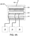
図4Aは、PoNサービスをサポートするPPPに基づくLAN交差接続構成の一例を示す。図4Aに示すように、LAN108を一例として用い、スイッチ230の全てのポートは、スイッチ230上のポートから従来のパッチ・パネル232の背面上にあるパンチ・ダウン・ブロックまでのケーブルを通じて、従来のパッチ・パネル232に接続されている。エンド・ユーザ・デバイス122〜126は、水平ケーブル配線およびPPP242の裏面上のパンチ・ダウン・ブロック(図示せず)を介して、PPP242に直接または間接的に接続することができる。パッチ・パネル232とPPP242との間の接続は、パッチ・パネル232の前面ポートとPPP242の前面ポートとの間のパッチ・コード接続を変更することにより、容易に確立および/または修正することができる。尚、図4Aに示すLAN交差接続構成の能力には影響を与えることなく、パッチ・パネル232およびPPP242の位置は相互交換可能であることを記しておく。更に、前述の構成のいずれかと建造物の水平ケーブル配線との間には、追加のパッチ・パネルも挿入することができる。
FIG. 4A shows an example of a PPP-based LAN cross-connect configuration that supports PoN services. As shown in FIG. 4A, using the
図4Bは、PoNサービスをサポートするPPPに基づくLAN相互接続構成の一例を示す。図4Bに示すように、LAN108を一例として用い、エンド・ユーザ・デバイス122〜126は、水平ケーブル配線およびPPP242の裏面上にあるパンチ・ダウン・ブロック(図示せず)を介して、PPP242に直接または間接的に接続することができる。スイッチ230とPPP242との間の接続は、スイッチ230の前面ポートとPPP242の前面ポートとの間のパッチ・コード接続を変更することにより、容易に確立および/または修正することができる。図4Bに示すような相互接続構成では、(水平ケーブル配線施設を介した)エンド・ユーザとスイッチとの間の接続を確立および/または除去および/または変更するのを担当する技術者は、スイッチ230に接近しなければならない。したがって、このような構成は、図4A及び図4Bに示す同等の交差接続構成よりも機密性が低いと見なされる。このような相互接続構成は、機密構成やスイッチ230に対するセキュリティ制御を必要としないネットワークに設置されるのが通例である。
FIG. 4B shows an example of a PPP interconnect LAN interconnect configuration that supports PoN services. As shown in FIG. 4B, using
先に実証したように、PPPは、単に従来のパッチ・パネルと交換し置き換えることによって、PoNサービスを新たなLANまたは既存のLANに挿入することができる。したがって、PPPは、交差接続構成(図4Aに示すような)および相互接続構成(図4Bに示すような)双方をサポートすることができる。 As demonstrated above, PPP can insert PoN services into a new or existing LAN simply by replacing and replacing the conventional patch panel. Thus, PPP can support both cross-connect configurations (as shown in FIG. 4A) and interconnect configurations (as shown in FIG. 4B).
建造物の水平ケーブル施設は、通例、水平ケーブル配線区分点として供する1つ以上の機器室パッチ・パネルにて終端する。加えて、パッチ・パネルに基づく区分点は、例えば、ケーブル設置業者から、例えば、機器を水平ケーブル施設に接続する担当のネットワーク技術者に水平ケーブル施設に対する責務を引き渡す前に、水平ケーブル施設内にあるそれぞれのネットワーク・ケーブルを、TIA分類5eおよび6に準拠することを容易に検査し、準拠することを証明可能とする。現行の業界慣例の下では、パッチ・パネル後部のパンチ・ダウン・ブロックは、水平ネットワーク・ケーブルに対して十分に信頼性があり安定した終端点であると見なされている。しかしながら、現行の業界標準の下では、ハブの前面上のRJ−45ジャックは、水平ネットワーク・ケーブルに対して十分に信頼性があり安定した終端点とは見なされていない。 A building's horizontal cable facility typically terminates in one or more equipment room patch panels that serve as horizontal cable routing points. In addition, a breakpoint based on the patch panel can be found in the horizontal cable facility, for example, before handing over responsibility for the horizontal cable facility from the cable installer to, for example, the network technician responsible for connecting the equipment to the horizontal cable facility. Each network cable can easily be checked for compliance with TIA classifications 5e and 6 and can be proven to be compliant. Under current industry practice, the punch-down block at the rear of the patch panel is considered a reliable and stable termination point for horizontal network cables. However, under current industry standards, the RJ-45 jack on the front of the hub is not considered a reliable and stable termination point for horizontal network cables.
したがって、PPPは交差接続構成および相互接続構成の双方をサポートすることができるが、パワー・ハブは交差接続構成をサポートすることしかできない。更に、(例えば、図3Aにおけるパッチ・パネル232またはパッチ・パネル234と置き換えることによって)交差接続構成においてPPP242を使用することにより、機器ラックや既存のケーブル施設/設備レイアウトに悪影響を及ぼすことなく、PoEサービスを既存の交差接続構成に導入することが可能となる。(図4Bに示すような)相互接続構成においてPPP242を用いて既存の交差接続構成または計画した交差接続構成と置き換えることにより、同等の交差接続構成に対してほぼ50%の全体的な空間の縮小となる。この縮小は、非受電ネットワークをPoEネットワークにアップグレードするときに、ラック空間管理には重要な場合もある。加えて、相互接続構成により、パワー・ハブと従来のパッチ・パネルとの間のパッチ・コードの必要性が解消し、これによって必要なケーブル数が減少し、LAN機器室内におけるケーブルの輻輳が減少し、ケーブルに関連するネットワーク接続不良の可能性が低下する。
Thus, PPP can support both cross-connect and interconnect configurations, but a power hub can only support cross-connect configurations. Furthermore, by using
他方で、パワー・ハブは、先に取り上げたように、既存の設備機器ラックの空間要件に悪影響を及ぼさずに既存の交差接続構成の中に投入することはできず、場合によっては、機器室の機器ラック数、設備レイアウト、およびケーブル施設のレイアウトに悪影響を及ぼすこともあり得る。更に先に取り上げた理由により、パワー・ハブは、相互接続構成をサポートすることができず、したがって相互接続構成を受け入れることができる設備において相互接続構成を用いることによって達成することができる空間の縮小を設備は利用することができない。 On the other hand, power hubs cannot be thrown into existing cross-connect configurations without adversely affecting the space requirements of existing equipment racks, as discussed above, and in some cases, equipment rooms The number of equipment racks, equipment layout, and cable facility layout may be adversely affected. For further reasons discussed above, the power hub cannot support the interconnect configuration, and thus can reduce the space that can be achieved by using the interconnect configuration in a facility that can accept the interconnect configuration. The facilities are not available.
要約すると、既存の機器室が交差接続または相互接続構成のどちらであるかには係わらず、PPPに基づく手法を用いれば、機器室の空間要件に影響を及ぼすことなくPoEを挿入することができる。PPP手法は、パワー・ハブに基づく手法では付帯したかもしれない、大規模なインフラストラクチャの計画および/またはインフラストラクチャのアップグレードを回避することができる。 In summary, regardless of whether the existing equipment room is cross-connected or interconnected, PoE can be inserted without affecting the space requirements of the equipment room using a PPP-based approach. . The PPP approach can avoid large-scale infrastructure planning and / or infrastructure upgrades that may have been associated with power hub-based approaches.
NMSの一例が、2005年8月24日に出願され、"SYSTEMS AND METHODS FOR NETWORK MANAGEMENT"(ネットワーク管理システムおよび方法)と題する米国特許出願第11/209,817号に記載されている。その内容は、この中で引用した全ての引例も含み、ここで引用したことにより本願に含まれるものとする。EMSは、NMSの特徴の少なくとも部分集合を設けるように適応させたNMSとすればよいが、NMSの特徴全てを含んでもよい。EMSは、特定の1組のインテリジェント・ネットワーク・デバイスの必要性を満たすように構成することができる。 An example of an NMS is filed on August 24, 2005 and is described in US patent application Ser. No. 11 / 209,817 entitled “SYSTEMS AND METHODS FOR NETWORK MANAGEMENT”. The contents include all references cited therein, and are incorporated herein by reference. The EMS may be an NMS adapted to provide at least a subset of NMS features, but may include all NMS features. The EMS can be configured to meet the needs of a specific set of intelligent network devices.
NMS110おおよびEMS112〜114(図1)のようなNMS/EMSは、ネットワーク・システム100を通じてインテリジェント・ネットワーク・デバイス(例えば、PPP)から検索することができるデバイス情報のデータベースを保持することができる。NMS/EMSは、更に、そのデータベースの中に、ネットワーク・システム100内にあるデバイスの接続性を記述する論理および物理トポロジ情報を保持することもできる。物理トポロジ情報は、ネットワーク・デバイス毎の一意の識別子、建造物/階/部屋番号識別子のようなネットワーク・デバイスの物理位置、ラック識別、特定したラックにおける位置、水平ケーブル配線作業領域の識別、および機器ラック、PPP、PPPポート、PPP電源等に対する位置を含むことができる。論理トポロジ情報は、PPP識別子、PPPポート番号、ジャック識別、水平ケーブルおよび作業領域ジャック識別、電源識別等のような、ネットワーク・デバイスの接続性を含むことができる。また、データベースはキー・ケーブル性能測定値も収容することができる。
NMS / EMS, such as
PPPは、PPPの位置、およびPPP内にあるポートの各々がサポートする作業領域の場所に関する物理位置情報の主レポジトリとして供することもできる。例えば、設置の時点において、論理および物理位置情報(例えば、建造物、階、部屋、GPS座標、IPアドレス、IPマスク、デフォルトIPゲートウェイ等)をPPPに設定することができる。PPPは、このような情報をNMS/EMSに供給し、こうして、NMS/EMS内に格納されている論理および物理位置情報が実際のネットワーク・ステータスと一致することを確認することができる。更に、各PPPポートをパンチ・ダウン・ブロックを介して着信ケーブルに配線する時点において、そのケーブルが担当する場所をPPPに入力することができる。例えば、PPPを水平ケーブル配線区分パッチ・パネルとして構成する場合、ケーブルがサポートする作業領域(例えば、建造物/階/作業領域/壁ジャック等)のような情報をPPPに入力し、不揮発性メモリに格納するとよい。PPPをスイッチ・パッチ・パネル・インターフェースとして構成する場合、ケーブルがサポートするスイッチ・ポート(例えば、建造物/階/機器室/スイッチ/ポート等)に関する情報を入力し、PPPに格納するとよい。このような位置情報は、定義インターフェース・ファイル(DIF:definition interface file)が指定するデータ構造で格納するとよい。単純ネットワーク管理プロトコル(SNMP)では、DIFは管理情報ベース(MIB:Management Information Base)に対応する。NMS/EMSが、PPPのDIFデータ構造に格納されている情報を要求する場合、PPPはこの要求に応答して、データ構造に格納されているデータをNMS/EMSに送信することができ、NMS/ENSはこのデータを内部の対応するデータ構造に格納することができる。例えば、NMS/EMSはPPP DIFが定義するデータ構造と同一のデータ構造を含むデータ構造のDIFを有するため、PPPのデータ構造における情報を検索し、NMS/EMS内の対応するデータ構造内に格納することができる場合もある。 The PPP can also serve as a main repository of physical location information regarding the location of the PPP and the location of the work area supported by each of the ports within the PPP. For example, logical and physical location information (eg, building, floor, room, GPS coordinates, IP address, IP mask, default IP gateway, etc.) can be set to PPP at the time of installation. The PPP can supply such information to the NMS / EMS, thus ensuring that the logical and physical location information stored in the NMS / EMS matches the actual network status. Furthermore, when each PPP port is wired to an incoming cable via a punch down block, the location that the cable is responsible for can be entered into the PPP. For example, when the PPP is configured as a horizontal cable wiring section patch panel, information such as the work area supported by the cable (for example, building / floor / work area / wall jack, etc.) is input to the PPP, and the nonvolatile memory It is good to store in. When configuring PPP as a switch patch panel interface, information regarding switch ports (eg, building / floor / equipment room / switch / port, etc.) supported by the cable may be input and stored in the PPP. Such position information may be stored in a data structure specified by a definition interface file (DIF). In the simple network management protocol (SNMP), the DIF corresponds to a management information base (MIB). If the NMS / EMS requests information stored in the PPP DIF data structure, in response to this request, the PPP can send the data stored in the data structure to the NMS / EMS, / ENS can store this data in the corresponding internal data structure. For example, since the NMS / EMS has a DIF having a data structure that includes the same data structure as defined by the PPP DIF, information in the PPP data structure is retrieved and stored in the corresponding data structure in the NMS / EMS. Sometimes you can.
更に、NMS/EMSはPPP制御パラメータを送りPPPを制御することができる。制御パラメータは、PPPおよびNMS/EMSに共通のDIFにしたがって格納し、効率的なデータ転送を達成できるようにするとよい。各ネットワーク・デバイスは一意のDIFを有することができる。このため、NMS/EMSはネットワーク・システム100内部、または制御および/または監視するように構成されているサブネット内における一意のDIF全てを格納する。
Furthermore, the NMS / EMS can send PPP control parameters to control the PPP. Control parameters may be stored in accordance with a DIF common to PPP and NMS / EMS so that efficient data transfer can be achieved. Each network device can have a unique DIF. Thus, the NMS / EMS stores all unique DIFs within the
図5から図8は、PPP400の構成例を示す。図5は、PPPフロント・パネル402の一例を示し、システム・ステータスLED410、複数のポート404、複数のポート・ステータスLED406を含むことができ、各LED406は1つのポート404に対応する。更に、TIA−606−Aに準拠する複数のポート・ラベル408、および例えば、ラック上に実装するたえの2つのラック実装ブラケット412も含む。
5 to 8 show configuration examples of the
図6は、PPPバック・パネル420の一例の背面図を示し、2つの電力入力ポート422および424、ネットワーク管理入力ポート426、ネットワーク管理出力ポート428、2つのステータスLEDそれぞれ426および428、グループ毎に3つのパンチ・ダウン・ブロック434から成る8つのグループに分けられた複数のパンチ・ダウン・ブロック434、ならびにPPP400の側面パネルから延出する1対のプレート436および438を含むことができる。プレート436および438は、パンチ・ダウン・ブロック434を物理損傷から保護する。例えば、プレート436および438は、パンチ・ダウン・ブロック434に損傷を与えることなく、平面上にPPP400を、その背面を下に向けて置くことを可能にする。
FIG. 6 shows a rear view of an example PPP back
図7に示すように、パンチ・ダウン・ブロック434は、水平ケーブル配線216のようなケーブルに、PPP400へのワイヤ接続を設ける。パンチ・ダウン・ブロック434への損傷があると、PPPが使用不能となる場合もある。したがって、プレート436および438は、パンチ・ダウン・ブロック434への損傷によってPPP400を逸失する危険性を低下させる。
As shown in FIG. 7, the punch down
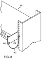
プレート436および438の各々は、接地点440として供する孔を含むことができる。図8に示すように、PPP400は、接地点440とラック上の点との間に接地ストラップ424を接続することによってラックに確実に接地することができる。
Each of the
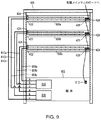
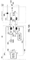
図9は、3つのPPP500a、500b、および500c、ならびにラック600上に実装した電源602の一例を示す。電源602は、単一の電源でもよく、あるいは多数の電源の組み合わせでもよい。例えば、電源602が2つの電源を含む場合、耐故障性を備えるようための冗長電源構成として、電源の各々をPPP500a〜500cの各々に独立して接続することができる。電源602は、電力出力ポート604a、604b、および604c、ならびに、オプションとして、冗長構成を実施する場合には、電力出力ポート606a、606b、および606cを含むことができる。例えば、電力接続部608a、608bおよび608cは、電力出力ポート604a〜604cをPPP500a〜500cの電力入力ポート422に接続することができ、電力接続部610a、610b、および610cは、冗長電源構成を用いる場合、電力出力ポート606a〜606cをPPP500a〜500cの電力入力ポート424に接続することができる。
FIG. 9 shows an example of three
図10は、各500a〜500cに含めることができるダイオード「OR」回路441を示す。これは、冗長電源構成において2つの電源からの電力を組み合わせる。電源602は、例えば、48ボルトを有するDC電力を供給することができ、電力接続部608a〜608c(または図12の942)および610a〜610c(または図12の944)は、2本のワイヤを含むことができ、1本が正そして1本が負である。48ボルトのDC電力に基づく手法は、内部110AC/DC電源を含むことを回避することにより、PPPにおける内部ファンの必要性をなくし、既存の従来からのパッチ・パネルと1対1でPPPが置き換わることを可能とする。電力入力ポート422および424の各々は、2つの接続点、1つが正そして1つが負、を含むことができるので、電力接続部608a〜608cおよび610a〜610cのワイヤは、電力入力ポート422および424の接続点の対応するものに、正を正に、そして負を負に接続する。
FIG. 10 shows a diode “OR”
ダイオート回路441は、2つのダイオード442および444、またはこれらのダイオードの機能をモデル化した同等の回路を含むことができる。ダイオード442〜444のカソード端子は、それぞれの電力入力ポート422および424の負の接続点に電気的に接続することができ、ダイオード442および444のアノード端子はノード446において互いに電気的に接続することができる。正の接続点はノード448に電気的に接続することができる。ノード446および448は、電力をPPP500a〜500cに供給する。ダイオード442および444は電源の1つからの電力が他の電源に流入するのを防止する。
The
図9に戻って、電源602は、NMS110、EMS112および/またはEMS114によって制御できるように、例えば、LAN108への接続のためにネットワーク・ポート1612を含むことができる。ネットワーク・ポート612は、例えば、ラック600の全てのPPP500a〜500cを接続するデイジー・チェーンの端部に接続することができる。図9は、LAN108のスイッチ230のポートに接続されているPPP500aのネットワーク管理入力ポート426と、PPP500bのネットワーク管理入力ポート426に接続されているPPP500aのネットワーク管理出力ポート428を示す。PPP500bのネットワーク管理出力ポート428は、デイジー・チェーンの最後のPPPまでラック600上に他のPPPがある場合、PPP500c等のネットワーク管理入力ポート426に接続することができる。最後のPPPのネットワーク管理出力ポート428は、電源602のネットワーク・ポート612に接続することができる。このように、ラック600の全てのPPP500a〜500cおよび電源602は、例えば、スイッチ230の1つのポートのみを用いて、LAN108に接続することができる。
Returning to FIG. 9, the
図11は、ネットワーク管理入力および出力ポート426および428、ならびに内部PPP回路とのインターフェースをサポートするPPP内部イーサネット・スイッチ450を示す。ネットワーク管理入力および出力ポート426および428のステータスは、それぞれ、(図6に示すように)ステータスLED430および432によって示すことができる。以下の表1は、ステータスLED、およびネットワーク管理入力および出力ポート426および428に関連する対応の条件の指示例を示す。
FIG. 11 shows a PPP

図12は、PPP900の一例における回路のブロック図を示し、PPP900は、ダイオード回路441、インライン電流管理部910、アナログ/ディジタル変換器948、パワー・プレーン904および908、共通回路902、ならびにポート回路906を含む。2つの電源を用いて耐故障性を設けると仮定すると、アナログ/ディジタル変換器948は2つの電源の電圧、ダイオード回路441のノード、ならびにインライン電流管理部910が発生する出力電圧を監視し、監視した電圧のディジタル値を、光カプラ918(光アイソレータとも呼ぶ)を介して、共通回路902のプロセッサ924に供給する。プロセッサ924は、インライン電流管理部910を通過する電流の値も受け取ることができる。これらの電圧および電流値は、以下のようなプロセスのために、プロセッサ924によって処理することができる。
FIG. 12 shows a block diagram of a circuit in an example of a PPP 900, which includes a
1.PPPの入力電力消費を判定する。
2.過去および現在の使用に基づいて、低電流および高電流状態に対するしきい値を計算する。
1. Determine the input power consumption of the PPP.
2. Calculate thresholds for low and high current conditions based on past and present usage.
3.電圧、電流および計算した電力測定値を含むイベント通知を、NMS110、EMS112および/またはEMS114に対して発生する。
4.ダイオード回路441において監視した電圧値が所定のしきい値未満またはこれを超過する場合、イベント通知をNMS110、EMS112および/またはEMS114に対して発生する。
3. An event notification is generated to
4). When the voltage value monitored in the
5.インライン電流管理部910を通過する電流が所定のしきい値未満またはこれを超過する場合、イベント通知をNMS110、EMS112および/またはEMS114に対して発生する。
5. If the current passing through the inline
6.PPPの電力消費が所定のしきい値未満またはこれを超過する場合、イベント通知をNMS110、EMS112および/またはEMS114に対して発生する。
これらおよびその他のイベント通知は、NMS110、EMS112および/またはEMS114によって、例えば、イベント通知に伴うデータを格納することにより、記録することができる。操作者は、ネットワーク・システム100を保守するために、GUIを用いてポート毎またはPPP毎に、記録したイベント通知を目視することができる。
6). An event notification is generated to
These and other event notifications can be recorded by
図12に示すように、インライン電流管理部910は、電流管理電力を共通回路902およびポート回路906に、別個にヒューズを設けた(それぞれ、ヒューズ912および914によって)パワー・プレーン904および908を介して、別個に出力する。インライン電流管理部、共通回路902、およびポート回路906の間の信号線は、光カプラ918および922、および/または容量性結合919によって絶縁されている。このように、パワー・プレーン904および908の1つにおける停電が、他のプレーン904または908に供給される電力に影響を及ぼすことを防止することができる。このように、ポート回路906のパワー・プレーン908への電力が落ちた場合でも共通回路902の動作は継続することができ、あるいは共通回路902のパワー・プレーン904の電力が落ちた場合でも、ポート回路906の動作は継続することができる。
As shown in FIG. 12, the inline
例えば、高電圧源がPPPに接続されているケーブルに偶然接続したことによってポート回路906が損傷しても、共通回路902の動作に影響を及ぼすことを防止することができる。このように、共通回路902は、ポート回路906の障害にも係わらず、ステータスを報告するというように、NMS110、EMS112および/またはEMS114と通信し続けることができる。共通回路902が損傷を受けても、同様に、ポート回路906の動作に影響を及ぼすことを防止する。このため、共通回路902への損傷にも係わらず、PoEサービスをPPPポートに提供し続けることができる。
For example, even if the
PPPの実施形態は、いずれの数のポート回路906でも含むことができる。各ポート回路は、絶縁されているパワー・プレーン908から電力を受けることができ、各ポート回路906は、ここに記載するように、指定数のポートをサポートすることができる。このように、個々のポート回路906が故障しても(例えば、電力サージまたはその他の何らかの原因により)、残りのポート回路906は正常に動作し続けることができる。
A PPP embodiment can include any number of
プロセッサ924は、制御システム・ステータスLED410を制御し、先に論じたように、種々のPPP状態を示すことができる。加えて、以下に羅列するような状態をシステム・ステータスLED状態によって示すことができる。
The
1.DHCPアドレシング(動的アドレス)、
2.電源ノイズ限度超過、
3.ファームウェア更新、
4.ファームウェア互換性、
5.ヒューズがとんだというような状態を示すことができる、パワー・プレーンの電力逸失、
6.入力電力の未受電、
7.プロセッサ初期化、
8.適正に動作しているポート回路、および
9.ポート回路の故障、および適正に動作する共通回路。
1. DHCP addressing (dynamic address),
2. Power noise limit exceeded,
3. Firmware update,
4). Firmware compatibility,
5. Power plane power loss, which can indicate a fuse blown condition,
6). Unreceived input power,
7). Processor initialization,
8). 8. Port circuit operating properly, and Port circuit failure and common circuit operating properly.
単一または多数の色および色間の切り換え、連続するLED色または点滅の速度、符号化パルス発生、および/または強度の変動というようなLED状態を、個々のPPP状態の指示に用いることができる。加えて、EDをオン状態に設定する代わりに点滅速度を用いて、電力を節約することもできる。以下の表2は、PPP900の異なる状態について可能なシステム・ステータスLEDの他の例を示す。 LED states such as single or multiple colors and switching between colors, continuous LED color or blink rate, encoding pulse generation, and / or intensity variation can be used to indicate individual PPP states. . In addition, power can be saved by using the blink rate instead of setting the ED to the on state. Table 2 below shows other examples of possible system status LEDs for different states of PPP 900.
図12に示すように、ポート回路906は、電流管理部934、PoE管理部936、LED管理部938、およびレガシー検出サポート回路940を、PPP900のポート毎に含むことができる。電流管理部934は、接続されているエンド・ユーザ・デバイスの各ポートを介して流れる電流を制御し監視することができる、状態機械のような制御ロジックを含むことができる。例えば、電流管理部934は、レジスタ内に設定した値に基づいて、電流の流れを制限する電流制限回路を含むことができる。
As shown in FIG. 12, the
図13は、電流管理部934の一例を示し、状態機械802、レジスタ804、ならびに電流リミッタおよびスイッチ806を含む。プロセッサ924は、レジスタ804内に制御値を設定することができる。状態機械802は、レジスタ804内の値に基づいて、電流リミッタおよびスイッチ806を制御することができる。例えば、プロセッサ924はレジスタ804内にしきい値を規定することができる。第1しきい値を絶対電流限度としてもよく、第2しきい値を、第1制御時間期間に超過してもよい電流限度としてもよい。ポートが第1しきい値を超過した場合、状態機械802は直ちに電流リミッタおよびスイッチ806に、例えば、スイッチを開放することにより電流の供給を停止するように指令することができる。加えて、状態機械802は、レジスタ804内の値を更新し(状態を変更する)、警報信号(イベント)を発生して、関連するポートに対して第1しきい値を超過したことを示すこともできる。
FIG. 13 shows an example of a
第2しきい値を超過すると、状態機械802は、レジスタ804を更新しタイマをオフに設定することによって、状態を変化させることができる。タイマが終了する前に電流が第2しきい値未満に低下した場合、状態機械802はその以前の状態に戻ることができ、あるいは状態機械802は第3状態に入り、ポートを再度オンにする前に、第2制御時間時間ポートをオフに切り換えることができる。また、状態機械は、例えば、第2しきい値を超過した回数を記録するために値をレジスタ804に設定し、プロセッサ924がレジスタ804内の値を受け取り、NMS110、EMS112、および/またはEMS114に報告できるようにしてもよい。
When the second threshold is exceeded,
プロセッサ924は、インライン電流管理部910が測定する電流値を経時的に監視することができる(過去の電力使用)。プロセッサ924は、周期的にこれらの測定値を用いて、PPP900への電流の流れを監視する際に用いる新たな電流しきい値を計算することができる。過去の電流使用に基づく電流しきい値は、異常な電流使用のより良い指標となることができる。
The
PoE管理部936は、各PPPポートを監視して、PoE受電デバイス(PD)の存在および特性を検出することができる。図14に示すように、PoE管理部936は、状態機械812のような制御ロジック、レジスタ814、およびPD質問器816を含むことができる。いずれの数の状態機械812、レジスタ814、およびPD質問器816でも、例えば、実施要件による指定され得るように、用いることができる。PoE PDを検出した場合、状態機械812は、レジスタ814を更新することによって状態を変化させ、続いてPeE PDのPoEクラスを決定する(分類)。一旦クラスを決定したなら、PoE管理部936は、例えば、IEEE802.3afに規定されているようなPDのPoEクラスに基づいて、PDに電力を供給する。PoE管理部936は、以下のような機能も実行することができる。
The
1.どのイーサネット・ケーブル対がPoEに電力を分配するか決定する。
2.検出するPoE機器の種類を制御する(即ち、IEEE802.3af機器のみ、レガシー機器、および/またはその他の種々雑多)。
1. Determine which Ethernet cable pair will distribute power to PoE.
2. Control the type of PoE device to detect (ie, IEEE 802.3af devices only, legacy devices, and / or other miscellaneous miscellaneous).
3. ポート毎にPoEサービスを活性化または非活性化する。
4. ポート毎に、PD PoE優先度および/または最大電力レベルを設定する。
5.ポート電力優先度を制御する制御パラメータを重要、高、および低の1つに設定することによって、ポート毎にPoE優先度を制御する。低電力の事態では、電力優先度が高い方のPDを切断するのは、電力優先度が低い方のポートへの電力を切断した後にしなければならない。
3. Activate or deactivate the PoE service for each port.
4). Set PD PoE priority and / or maximum power level for each port.
5. The PoE priority is controlled for each port by setting the control parameter that controls the port power priority to one of important, high, and low. In a low power situation, the higher power priority PD must be disconnected after the power to the lower power priority port is disconnected.
6.ポート毎にPoE検出技法を制御する。
7.ポート毎にPoE PD電力分類を制御する。PD電力分類は、PDが消費すると予期され得る電力量を示す。
6). Control the PoE detection technique for each port.
7). Control PoE PD power classification for each port. The PD power classification indicates the amount of power that can be expected to be consumed by the PD.
状態機械812は、レジスタ814にプロセッサ924が格納した制御パラメータによって制御することができる。例えば、プロセッサ924は、「停止ビット」をレジスタ814内に設定することによって、あるポートに電力の供給を停止させることができる。「停止ビット」は、状態機械814の状態を変化させることができ、これに応答して、例えば、スイッチを開放してPDへの電力を切断する。状態機械812は、1つ以上の警告メッセージ(イベント)をプロセッサ924に送ることによって、またはレジスタ814を新たなステータス情報で更新することによって、ポート・ステータスの変化をプロセッサ924に報告することができる。プロセッサ924は、レジスタ814の内容を読み取ることによって、ステータス情報を得ることができる。
The state machine 812 can be controlled by control parameters stored in the
PoE管理部926がプロセッサ924に供給するステータス更新は、以下のような状態を示すことができる。
1.PPPポートに取り付けられているPDがない。
The status update supplied by the PoE management unit 926 to the
1. There is no PD attached to the PPP port.
2.PPPポートを通じて配給されている電力がない。
3.PPPポートを通じて電力が供給されている。
4.PDが検出されたが、その電力要件を判断することができない。
2. There is no power being distributed through the PPP port.
3. Power is supplied through the PPP port.
4). PD is detected, but its power requirements cannot be determined.
プロセッサ924は、イベント通知を通じて、このようなステータス更新をPoE管理部936からNMS110、EMS112、および/またはEMS114に中継する。このように、NMS110、EMS112、および/またはEMS114は、精度高いポート・レベルの接続およびPoE関連情報を維持することができる。
The
LED管理部938は、ポートLED406を制御し、図15に示すように、状態機械822のような制御ロジック、レジスタ824、およびLED駆動回路826を含むことができる。状態機械822は、プロセッサ924が設定することができるレジスタ824内の値に基づいて、LED駆動回路826を制御する。例えば、プロセッサ924は、NMS110、EMS112、および/またはEMS114から受信した移動/追加/変更要求に応答してレジスタ824内に値を設定することによって、特定のポートのLED406を指定速度で点滅させることができる。単一または多数の色および色間の切り換え、連続するLED色または点滅の速度、符号化パルス発生、および/または強度の変動というようなその他のLED状態も、個々のPPP状態の指示に用いることができる。状態機械822は、プロセッサ924が設定するレジスタ824内の値に基づいて、LED駆動回路826を制御することができる。
状態機械822は、実行しつつある現在のLED機能に基づいて、レジスタ824内の値を変化させて、関連するポートのステータスを反映し、プロセッサ924が監視機能を事項するときに、そのステータスを読み取れるようにすることができる。LED406を用いると、以下のようなポート状態を指示することができる。
The
1.接続したPDの電力分類に対する電力レベル指標、
2.ポートから除去した電力(ロック・ダウン)、分類毎に全てのポートについての過電流、
3.個々のポートについての過電流状態(管理上の制約)、
4.接続されているデバイスが受電スイッチ(powered switch)であることによる電力供給のバック・オフ(back off)、
5.PD電圧不適合性、
6.ポート電力インターフェース不良、
7.電力分類不備、および
8.制限外のポート・パワー・ノイズ。
加えて、LED406は、パッチ・コードの追跡および/または直接パッチ・コード除去/変更のために操作者を補助するために用いることができる。
1. Power level indicator for the power classification of the connected PD,
2. Power removed from port (lock down), overcurrent for all ports per classification,
3. Overcurrent condition for individual ports (management constraints),
4). Back off power supply because the connected device is a powered switch,
5. PD voltage incompatibility,
6). Bad port power interface,
7). 7. Incorrect power classification, and Unrestricted port power noise.
In addition,
他のLED機能も同様に、例えば、色のように、プロセッサ924によって設定することができる。加えて、状態機械822は、LED駆動回路826を介してLED406を制御し、関連するポートの状態に基づいて、特定の機能を実行することができる。この主の制御の例を以下の表3に示す。
Other LED functions can be similarly set by the
レガシー検出サポート回路940は、PoE管理部936およびプロセッサ924と共に、図16に示す一例のプロセス1500を実行する。プロセス1500は、ポートに接続されているエンド・ユーザPDが、IEEE802.3afと互換性のあるデバイスというような第1種類のPoEデバイス、またはレガシーデバイスのような第2種類のPoEデバイスのどちらか判定を行う。
The legacy
ステップ1502において、プロセスは、ポートが第1種PDに接続されているか否か判定を行う。例えば、第1種PDがIEEE802.3af PoEデバイスである場合、IEEE802.3af規格において指定されている手順によってこれを検出することができる。第1種PDが検出された場合、プロセスはステップ1504に進み、それ以外の場合、ステップ1502において、所定の遅延の後に検出プロセスを繰り返すことができる。ステップ1504において、プロセスはPoE PDを分類する(PoEデバイスに質問することによって電力要件を判定する)ことができ、プロセスはステップ1510に進む。ステップ1510において、プロセスは、判定した分類に応じて電力をPoE PDに供給することができ、このポートと関連するLEDを、レジスタ824の内容によって指定される状態に設定することができ、オプションとしてレジスタ824内の状態フィールドを更新することができる。次に、プロセスはステップ1512に進む。
In
ステップ1512において、プロセスは、ポートのステータスに変化があったか否か、例えば、接続されていたPDが切断されたか否かについて判定を行う。変化があった場合、プロセスはステップ1502に戻る。それ以外の場合、プロセスはステップ1514に進む。ステップ1514において、プロセスは、PPPがオフになっているか否か判定を行う。PPPがオフになっている場合、プロセスはステップ1516に進み終了する。それ以外の場合、プロセスはステップ1512に戻る。
In
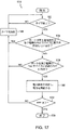
プロセス1500が実行している間、タイマに基づいて、図17に示すような他のプロセス1550を実行し、第1種のデバイスが接続されているか否か判定を行うこともできる。第1種類のデバイスが接続されていない場合、プロセスは、第2種検出プロセスを実行する。ステップ1552において、プロセスはタイマが終了しているか否か判定を行う。終了している場合、プロセスはステップ1554に進み、それ以外の場合、プロセスはステップ1552に戻る。ステップ1554において、プロセスは、ポートが第1種類または第2種類のPoE PDに電力を供給しているか否か判定を行う。ポートが電力を供給している場合、プロセスはステップ1556に進み、それ以外の場合、プロセスはステップ1558に進む。ステップ1556において、タイマを設定し、プロセスはステップ1552に戻る。
While the
ステップ1558において、プロセスは、ポートが、レガシーデバイス(PoE PDのIEEE802.3afに関してレガシー)のような、第2種類のデバイスに接続されているか否か判定を行う。このような判定をどのように行えばよいかの例を図18Aに示す。これは、ワイヤ対4/5および7/8上でPoN電力を受電するように構成されているレガシーPDの一例に、4対の撚り線対ケーブルを通じて接続されているPPPレガシー検出サポート回路940の一例を示す。レガシー検出サポート回路940は、ワイヤ対のワイヤ4、5上に、送信ドライバ1204および変圧器1206を介して、発振信号を送信する発振信号発生器1202を含むことができる。
In
レガシーPDは、ケーブルがこのPDに挿入されると、物理スイッチ1210が開放位置から閉鎖位置に移動するように構成することができる。したがって、PDがレガシーデバイスである場合、発振信号発生器がワイヤ対のワイヤ4、5上に放出した発振信号は、変圧器1208および1212を介してワイヤ対7/8に送信され、受信機1216および変圧器1214を介して、検出回路1218によって検出される。PDがレガシーデバイスでない場合、物理スイッチ1210は開放位置のままであり、検出回路1218は、発振信号出力に応答して対応する信号を受信しない。信号が受信されない場合、検出回路1218は、PDがレガシーデバイスではないと判定する。
The legacy PD can be configured such that the physical switch 1210 moves from the open position to the closed position when a cable is inserted into the PD. Thus, if the PD is a legacy device, the oscillating signal emitted by the oscillating signal generator onto the
検出回路1218が、接続されているPDがレガシーデバイスであると判定した場合、検出回路1218は(図18Aには示されていない接続線を通じて)極性逆転スイッチ1220と通信し、図18Bに示すように、リード1222および1224間に負の電圧を加える。検出回路1218が、接続されているPDがレガシーデバイスでないと判断した場合、検出回路1218は極性逆転スイッチ1220と通信し、リード1222および1224間に正の電圧を加える。このように、しかるべき電圧をリード1222および1224上に加え、変圧器1206および1214におけるワイヤ・タップを介して、そしてワイヤ対4/5および7/8をそれぞれ通じて、PDデバイスにおける変圧器1208および1212上のワイヤ・タップに電力を送信する。変圧器1208および1212上のワイヤ・タップにおいてPDデバイスによって受電された電力は、ダイオード回路1228を有するPD回路1226を介して配給され、PD負荷1230を駆動する。
If the
図17に戻り、第2種類のPoE PDが検出された場合、プロセスはステップ1506に進み、それ以外の場合、プロセスはステップ1556に進む。ステップ1556において、プロセスは、第2種類のデバイスの電力要件を判定し、要求電力を供給し、ステップ1562に進む。ステップ1562において、プロセスはPPPがオフになっているか否か判定を行う。オフになっている場合、プロセスはステップ1564に進み、それ以外の場合、プロセスはステップ1556に進む。
Returning to FIG. 17, if a second type of PoE PD is detected, the process proceeds to step 1506, otherwise the process proceeds to step 1556. In
ポート回路906の内部にある管理部(即ち、電流管理部934、PoE管理部936、およびLED管理部938)は、独立した状態機械として動作することができ、プロセッサ924と双方向処理を行い、プロセッサ924から制御パラメータ更新を受け取り、ステータス更新をプロセッサ924に供給する。先に記したように、ポート回路906は、プロセッサ924とは独立して動作することができる。例えば、PPPが停電、リセット、または自己検査する場合、意図的であれ(例えば、新たにダウンロードしたプロセッサ・コードを現場にて更新するため)または非意図的であれ(停電または内部障害発生リセットのため)、ポート回路処理は影響を受けずに済み、ポート回路906は、プロセッサ924から受信した最新のパラメータに基づいて、PPPポートへのPoEに基づくサービスをサポートし続けることができる。一旦プロセッサ924が再度動作可能となったなら、プロセッサ924とポート回路906との間には正常な通信を再開することができる。
The management units (i.e.,
図12に戻り、共通回路902はプロセッサ924と、ランダム・アクセス・メモリ(RAM)928および不揮発性メモリ930を含むことができるメモリ926と、2ポート・イーサネット・スイッチ932とを含むことができる。PPP制御パラメータ、ならびに位置および接続情報や関連するDIFというような構成データが不揮発性メモリ930に格納されている場合、PPP900は、例えば、電力が偶然失われPPP900を再起動させる場合、格納されているPPP構成に戻ることができる。不揮発性メモリ930に格納することができる制御および構成パラメータは、以下を含むことができる。
Returning to FIG. 12, the
1.PPP構成パラメータ、
2.PPPおよびPoEに関連する電流および電圧しきい値、
3.PPPネットワークIP構成データ、
4.イベント通知(例えば、SNMPトラップ)の受信側、および
5.PPPアイデンティティ、PPP物理位置情報、ならびに関連する電源識別および位置情報。
1. PPP configuration parameters,
2. Current and voltage thresholds associated with PPP and PoE;
3. PPP network IP configuration data,
4). 4. event notification (eg, SNMP trap) receiver; PPP identity, PPP physical location information, and associated power supply identification and location information.
プロセッサ924は、メモリ926に格納されている制御パラメータおよびデータに基づいて、PPP900の動作を制御することができ、イーサネット・スイッチ932を介して他のデバイスと通信することができる。メモリ926は、プロセッサ924が実行することができるソフトウェアを格納するために用いることができる。プロセッサ924は、受信した制御パラメータに基づいて、レジスタ804、814、および824を設定することにより、ポート回路906を制御しその機能を実行することができる。加えて、プロセッサ924は以下の機能を実行することもできる。
The
1.PoE PDがAC/DC PoE検出またはDCのみの検出のどちらを受信したかに基づいてポートを制御する。
2.NMS/EMSによるポート・レベル値の制御/管理がPPPによって受け入れられるか否か制御する。
1. The port is controlled based on whether the PoE PD has received AC / DC PoE detection or DC only detection.
2. Controls whether port level value control / management by NMS / EMS is accepted by PPP.
3.電力を送信するためのワイヤの割り当てを変更できるか否か制御する。
NMS110、EMS112、およびEMS114はGUIとインターフェースすることができる。GUIは、操作者がネットワークを保守および制御し、所望の方針を管理することを可能にする。例えば、このようなGUIによって、操作者は監視電力、ならびにPPPおよび当該PPPに接続されているデバイスというようなデバイスの1つ以上の不良ステータスを、グラフィックを用いて視認することが可能となる。
3. Controls whether the assignment of wires for transmitting power can be changed.
GUIは、ネットワーク・システム100のトポロジのグラフィック表示を提供することができる。この表示はツリー状に編成することができ、ツリーの各ブランチはネットワーク・システム100のサブネットワーク(サブネット)を形成することができる。GUIは、例えば、機器クローゼット206およびラック600のような、PPPを配置することができる建造物の物理的な面を詳細に描いた床配置図のような、実際の物理位置に関してサブネットを教示することができる。GUIは、以下のような表示を行うことができる。
The GUI can provide a graphical display of the topology of the
1.全てのPPPの階層図、
2.PPPの一覧、
3.記録したイベントおよび通知を含む、選択したラックのPPP毎の情報、
4.a.PPPが発生するイベント通知のメッセージ記録、
b.PPP毎の現在および過去の電力使用値、および
c.物理位置および論理接続情報、
を含む、特に選択したPPPについての詳細な構成、制御およびステータス情報。
GUIは、IPアドレスの範囲から選択したサブネットのパネルを探索し、各PPPのポート毎に情報を視認および/または変更する等というような機能をサポートする能力を備えることもできる。
1. Hierarchical diagram of all PPPs,
2. PPP list,
3. Information for each PPP of the selected rack, including recorded events and notifications,
4). a. A message recording of event notifications when PPP occurs,
b. Current and past power usage per PPP, and c. Physical location and logical connection information,
Detailed configuration, control and status information for the selected PPP, including
The GUI may also be capable of supporting functions such as searching for a panel of subnets selected from a range of IP addresses and viewing and / or changing information for each PPP port.
ネットワーク・トポロジは、必要な情報を明示的に要求するかまたは局所監視機能によって得られたPPPからの非要請通知を受信することによって、PPPから導出することができる。例えば、PPPから受信することができるデータは以下を含むことができる。 The network topology can be derived from PPP by explicitly requesting the required information or by receiving unsolicited notifications from PPP obtained by the local monitoring function. For example, data that can be received from PPP can include:
1.部屋の識別、ラックの識別、水平ケーブル配線作業室識別というような物理位置情報。
2.PPPおよびポート識別、スイッチ・ポート識別、電源元識別というような接続情報。
1. Physical location information such as room identification, rack identification, horizontal cabling work room identification.
2. Connection information such as PPP and port identification, switch port identification, and power source identification.
3.受電デバイスがポートに接続されていれるか否か。
4.電流消費量。これは、PPPのようなインテリジェント・ネットワーク・デバイスには特に関連がある。何故なら、PPPはそのポートに電力を供給し、PPPを通じて供給される電力の総量を、ネットワークの電力予算の目的のために監視できるからである。
3. Whether the powered device is connected to the port.
4). Current consumption. This is particularly relevant for intelligent network devices such as PPP. This is because PPP supplies power to its port and the total amount of power supplied through PPP can be monitored for network power budget purposes.
5.PPPのPD質問技法に基づいて、切断されていると思われる、受電PDへの電力の異常終了に関する情報(例えば、PD識別子およびPPPポート識別子)。
6.電力消費が指定限度を超過しているPDのような、違反PD。
5. Information related to abnormal termination of power to the receiving PD (eg, PD identifier and PPP port identifier) that appears to be disconnected based on PPP's PD interrogation technique.
6). A violation PD, such as a PD whose power consumption exceeds a specified limit.
7.PPP電力消費がしきい値未満に低下したこと。
8.PPP電力消費がしきい値を超過したこと。
9.PPP物理位置を変更したこと。
7). PPP power consumption has dropped below a threshold.
8). PPP power consumption has exceeded a threshold.
9. The PPP physical location has changed.
10.PPP着信電圧が所望の範囲外であること(例えば、高過ぎるかまたは低過ぎる)。
11.PPP電力ヒューズがとんだこと。
10. The PPP incoming voltage is outside the desired range (eg, too high or too low).
11. The PPP power fuse is dead.
12.PPPへの着信電力量。
13.PPPが検出した管理ポート接続。
14.PPPが検出した管理ポート切断。
12 Incoming power to PPP.
13. Management port connection detected by PPP.
14 Management port disconnection detected by PPP.
操作者はGUIを用いて、PPPの種々のパラメータを設定することにより、ネットワーク・システム100を制御することができる。例えば、操作者は下記のことを行うことができる。
An operator can control the
1.あらゆるPPPを監視することによって保守を行う(例えば、検査信号を送ることによりポート接続を検証し、PPPへの接続を確認する等)、
2.PPPのいずれのポートに対しても、出力電力に優先順位を指定する。例えば、ポートに低、高、または至高優先度を指定することができる。
1. Perform maintenance by monitoring any PPP (eg, verify port connection by sending a test signal, confirm connection to PPP, etc.),
2. For any port of PPP, a priority order is specified for output power. For example, a port can be assigned a low, high, or supreme priority.
3.PPPまたはそのポートのいずれの電力消費に対してもしきい値を設定する。例えば、このようなしきい値は電流および/または電圧値の形態で設定することができる。
4.例えば、PPPに対する電力入力の電流および電圧をリアルタイムで監視し、しきい値を設定する。しきい値は、警報状態の検出のために設定することができる。
3. A threshold is set for the power consumption of either PPP or its ports. For example, such threshold values can be set in the form of current and / or voltage values.
4). For example, the current and voltage of the power input to the PPP are monitored in real time and the threshold is set. The threshold can be set for alarm condition detection.
5.例えば、2つの電源によってPPPに給電するときに、電圧または電流というような、第1電源のパラメータ、第2電源のパラメータ、および加算点におけるパラメータというようなパラメータを監視する。 5. For example, when powering a PPP by two power sources, parameters such as a first power source parameter, a second power source parameter, and a summing point parameter, such as voltage or current, are monitored.
6.PPPの全てのポートに最大電力を出力するコマンド、
7.PPPまたは当該PPPの1つ異常のポートについて、電力消費を検出し表示する。
6). Command to output maximum power to all ports of PPP,
7). Power consumption is detected and displayed for PPP or one abnormal port of the PPP.
8.例えば、設置時に動的(DHCP)または静的IPアドレスをPPPに割り当てる。
9.PPPポートへの電力サービスを選択的に非活性化/再活性化する。
8). For example, a dynamic (DHCP) or static IP address is assigned to the PPP during installation.
9. Selectively deactivate / reactivate power service to the PPP port.
10.PPPのLEDの動作を制御する(例えば、点滅速度、オン/オフ等)、および
11.PPPのポート毎に電力モード(例えば、通常、強制、またはデバイス・チェックを伴う強制)を指定する。例えば、「通常」電力モードでは、PPPは、デバイスがポートに接続されているか否か、および/またはポートに接続されているデバイスの種類、および/または電力消費監視に基づいて、ポートへのPoE電力の印加を管理することができる。「デバイス・チェックを伴う強制」電力モードでは、PPPは、接続されたデバイスの種類に関係なく、および/または電力消費の監視をせずに、デバイスがポートに接続されたときに、このポートにPoE電力を印加することができる。「強制」電力モードでは、PPPは、デバイスをチェックせずに、または電力消費を監視せずに、PoE電力をオートに印加することができる。
10. 10. Control the operation of the PPP LEDs (eg, blink rate, on / off, etc.), and Specify a power mode (eg, normal, forced, or forced with device check) for each PPP port. For example, in a “normal” power mode, PPP can determine whether a device is connected to a port and / or the type of device connected to the port, and / or power consumption monitoring. The application of power can be managed. In the “force with device check” power mode, PPP will not connect to this port when a device is connected to the port, regardless of the type of device connected and / or without power consumption monitoring. PoE power can be applied. In “forced” power mode, PPP can apply PoE power to auto without checking the device or monitoring power consumption.
これまでに開示した特徴および機能ならびにその他の特徴および機能、あるいはその代替物の種々のものを、望ましければ、他の多くの異なるシステムまたは用途に組み込めることは認められよう。例えば、単数(冠詞の「a」)は、1つ以上の要素の使用を示すことがある。ここに提示した一覧は、限定ではなく例示であることを意図している。また、現在予測できない変形、あるいは予期できない代替物、変更物、変形またはその中における改良も、後に当業者によって行うことができ、特許請求の範囲によって包含されることも意図している。 It will be appreciated that the features and functions disclosed so far, as well as various other features and functions, or alternatives thereof, can be incorporated into many other different systems or applications, if desired. For example, the singular (the article “a”) may indicate the use of one or more elements. The list presented here is intended to be illustrative rather than limiting. Also, variations that are not currently foreseeable, or unforeseen alternatives, modifications, variations or improvements therein can be made later by those skilled in the art and are intended to be encompassed by the claims.
Claims (17)
制御パラメータを格納するメモリと、
複数のポートであって、各々がネットワーク通信接続をサポートするように構成された、ポートと、
プロセッサであって、前記複数のポートのうちの少なくとも1つを、前記制御パラメータに基づいて、前記ネットワーク通信接続を通じて受電デバイスに選択的に電力を供給するように構成するプロセッサと、
第1電力入力ポートおよび第2電力入力ポートであって、それぞれが正端子および負端子を備え、前記第1電力入力ポートからの電力を、前記第2電力入力ポートからの電力と組み合わせて単一の電源とする、第1電力入力ポートおよび第2電力入力ポートと、
第1ダイオードおよび第2ダイオードであって、前記第1ダイオードが前記第1電力入力ポートの正または負端子のいずれかに接続し、第2ダイオードがそれに対応する前記第2電力入力ポートの端子に接続し、前記第1ダイオードおよび前記第2ダイオードは第1ノードに接続し、前記第1電力入力ポートおよび前記第2電力入力ポートの正または負端子の内、前記第1ダイオードおよび前記第2ダイオードの一方に接続されていない端子は第2ノードに接続される、第1ダイオードおよび第2ダイオードと、
接続された受電デバイスに電力を供給するために、前記第1ノードおよび前記第2ノードに接続するインライン電流管理部と、
前記第1電力入力ポートおよび前記第2電力入力ポートならびに前記第1ノードおよび前記第2ノードの電圧を監視するように構成されたアナログ/ディジタル変換器であって、前記プロセッサが、前記アナログ/ディジタル変換器が監視する前記電圧に基づいて、前記第1電力入力ポートおよび前記第2電力入力ポートに供給される電力のステータスを判定するように構成されたアナログ/ディジタル変換器と、
を備えた、受電パッチ・パネル。 A receiving patch panel,
Memory for storing control parameters;
A plurality of ports, each configured to support a network communication connection; and
A processor, wherein at least one of the plurality of ports is configured to selectively supply power to a powered device over the network communication connection based on the control parameter;
A first power input port and a second power input port, each comprising a positive terminal and a negative terminal, wherein the power from the first power input port is combined with the power from the second power input port to provide a single A first power input port and a second power input port,
A first diode and a second diode, wherein the first diode is connected to either the positive or negative terminal of the first power input port, and the second diode is connected to the corresponding terminal of the second power input port; The first diode and the second diode are connected to a first node, and the first diode and the second diode of positive and negative terminals of the first power input port and the second power input port are connected to each other. A terminal not connected to one of the first and second diodes connected to the second node;
An in-line current management unit connected to the first node and the second node to supply power to the connected power receiving device;
An analog / digital converter configured to monitor the voltages of the first power input port and the second power input port and the first node and the second node, the processor comprising the analog / digital converter An analog / digital converter configured to determine a status of power supplied to the first power input port and the second power input port based on the voltage monitored by the converter;
Power receiving patch panel with
別個に給電される第1パワー・プレーンおよび第2パワー・プレーンと、
共通回路と、
ポート回路であって、前記第1パワー・プレーンが前記共通回路に電力を供給するように構成され、前記第2パワー・プレーンが前記ポート回路に電力を供給するように構成された、ポート回路と、
前記第2パワー・プレーンから電力を受けるレジスタであって、前記共通回路が電源アイソレータを介して前記ポート回路と通信する、レジスタと、
を備えた、受電パッチ・パネル。 The power receiving patch panel of claim 1, further comprising:
Separately powered first and second power planes;
A common circuit;
A port circuit, wherein the first power plane is configured to supply power to the common circuit, and the second power plane is configured to supply power to the port circuit; ,
A register receiving power from the second power plane, wherein the common circuit communicates with the port circuit via a power isolator;
Power receiving patch panel with
レーンに接続されており、前記インライン電流管理部は、前記接続される受電デバイスに前記ヒューズの1つを介して接続された、受電パッチ・パネル。 2. The power receiving patch panel according to claim 1 , wherein the inline current management unit is connected to independent power planes in charge of different parts of the power receiving patch panel through independent fuses, The management unit is a power receiving patch panel connected to the connected power receiving device via one of the fuses.
レガシー検出サポート回路と、
第1位置および第2位置を有するスイッチと、
を備えており、前記レガシー検出サポート回路は、
第1電流および第2電流に基づいて、前記ポートに接続された前記受電デバイスの特性を判定し、
第1検査電圧が前記スイッチに印加されているとき前記第1位置にある前記スイッチを介して前記第1電流を測定し、第2検査電圧が前記スイッチに印加されているとき前記第2位置にある前記スイッチを介して前記第2電流を測定する、
ように構成された、受電パッチ・パネル。 The power receiving patch panel of claim 1, further comprising:
Legacy detection support circuit,
A switch having a first position and a second position;
And the legacy detection support circuit includes:
Determining a characteristic of the power receiving device connected to the port based on the first current and the second current;
The first current is measured through the switch in the first position when a first test voltage is applied to the switch, and is in the second position when a second test voltage is applied to the switch. Measuring the second current through the switch;
Received patch panel configured as follows.
1つ以上の制御パラメータを前記受電パッチ・パネルに格納し、
前記1つ以上の制御パラメータに基づいてネットワーク通信接続を通じて受電デバイスに選択的に電力を供給するように、前記受電パッチ・パネルの複数のポートのうちの少なくとも1つを構成し、さらに、
第1電源および第2電源から電力を受け、
前記第1電源および前記第2電源からの電力を、単一の電源に組み合わせて、前記複数のポートのうちの少なくとも1つを介して受電デバイスに電力を供給し、
前記第1電源の第1端子を第1ダイオードに接続し、
前記第2電源の第1端子を第2ダイオードに接続し、
前記第1ダイオードおよび前記第2ダイオードを第1ノードに接続し、
前記第1電源の第2端子と前記第2電源の第2端子とを第2ノードに接続し、
インライン電流管理部を前記第1ノードおよび前記第2ノードに接続して、前記複数のポートのうちの少なくとも1つを介して電力を受電デバイスに供給し、
前記第1電源および前記第2電源並びに前記第1ノードおよび前記第2ノードのアナログ電圧をディジタル値に変換し、
前記ディジタル値に基づいて前記第1電源および前記第2電源のステータスを識別する、
方法。 A method of supplying power to one or more power receiving devices connected to a power receiving patch panel comprising:
Storing one or more control parameters in the received patch panel;
Configuring at least one of the plurality of ports of the powered patch panel to selectively power a powered device through a network communication connection based on the one or more control parameters ; and
Receiving power from the first power source and the second power source,
Combining power from the first power source and the second power source into a single power source to supply power to the power receiving device via at least one of the plurality of ports;
Connecting a first terminal of the first power supply to a first diode;
Connecting a first terminal of the second power source to a second diode;
Connecting the first diode and the second diode to a first node;
Connecting a second terminal of the first power source and a second terminal of the second power source to a second node;
Connecting an inline current management unit to the first node and the second node to supply power to the power receiving device via at least one of the plurality of ports;
Converting analog voltages of the first power source and the second power source and the first node and the second node into digital values;
Identifying the status of the first power source and the second power source based on the digital value;
Method.
前記1つ以上の制御パラメータのうちの少なくとも1つとして電流制限しきい値を格納し、
前記電流制限しきい値に基づいて前記複数のポートのうちの少なくとも1つに対して1つ以上の電流制限を設定する、方法。 9. The method of claim 8 , further comprising:
Storing a current limit threshold as at least one of the one or more control parameters;
Setting one or more current limits for at least one of the plurality of ports based on the current limit threshold.
共通回路およびポート回路に電力を別個に供給し、
前記共通回路と前記ポート回路との間の通信を、電源アイソレータを介して行われるように制限し、
レジスタを用いて前記ポート回路を制御する、方法。 9. The method of claim 8 , further comprising:
Supply power to common circuit and port circuit separately,
Limiting communication between the common circuit and the port circuit to be performed via a power isolator,
A method of controlling the port circuit using a register.
第1検査電圧をポートに印加し、第1電流を測定し、
第2検査電圧を前記ポートに印加し、第2電流を測定し、
前記第1電流および前記第2電流に基づいて、前記ポートに接続された受電デバイスの特性を判定する、方法。 9. The method of claim 8 , further comprising:
Applying a first test voltage to the port, measuring a first current;
Applying a second test voltage to the port and measuring a second current;
The first current and on the basis of the second current, determines characteristics of the connected power receiving device to the port, the method.
複数のポートであって、各々がネットワーク通信接続をサポートするように構成されたポートと、
制御パラメータを格納し、該制御パラメータに基づいて前記受電パッチ・パネルを制御する共通回路と、
前記制御パラメータの1つ以上に基づいて、ネットワーク通信接続を通じて前記ポートのうちの1つに接続された受電デバイスに電力を供給するポート回路と、
前記共通回路に電力を供給する共通回路パワー・プレーンと、
前記ポート回路に電力を供給するポート回路パワー・プレーンと、
電源から電力を受け取るダイオード回路と、
前記ダイオード回路から電力を受け、前記共通回路パワー・プレーンおよび前記ポート回路パワー・プレーンに電力を供給するインライン電流管理部と、
前記ダイオート回路から受ける電力および前記インライン電流管理部によって出力される電力を監視するアナログ/ディジタル変換器と、
前記アナログ/ディジタル変換器から、前記ダイオード回路が前記第1電源から受けた電圧、前記ダイオード回路が前記第2電源から受けた電圧、前記インライン電流管理部から出力される電力、または前記インライン電流管理部から出力される電流のうちの少なくとも1つのディジタル表現を受け取り、該ディジタル表現を前記共通回路に中継する第1光カプラと、
前記制御パラメータを前記共通回路から前記ポート回路に中継する第2光カプラと、
を備えた、受電パッチ・パネル。 A receiving patch panel,
A plurality of ports, each configured to support a network communication connection;
A common circuit for storing control parameters and controlling the power receiving patch panel based on the control parameters;
A port circuit for supplying power to a powered device connected to one of the ports through a network communication connection based on one or more of the control parameters;
A common circuit power plane for supplying power to the common circuit;
A port circuit power plane for supplying power to the port circuit;
A diode circuit that receives power from the power source;
An inline current manager that receives power from the diode circuit and supplies power to the common circuit power plane and the port circuit power plane;
An analog / digital converter that monitors power received from the die auto circuit and power output by the in-line current management unit;
The voltage received by the diode circuit from the first power supply from the analog / digital converter, the voltage received by the diode circuit from the second power supply, the power output from the inline current management unit, or the inline current management A first optical coupler that receives at least one digital representation of the current output from the unit and relays the digital representation to the common circuit;
A second optical coupler that relays the control parameter from the common circuit to the port circuit;
Power receiving patch panel with
レジスタに設定されており前記共通回路から受け取る値に基づいて、前記ネットワーク通信接続を通じて前記受電デバイスへの電流の流れを制限する電流管理部と、
ポートに接続された受電デバイスの存在および特性を検出するために、前記ポートを監視するPoE管理部と、
レジスタ内にあり前記共通回路から受け取る値に基づいて、ポートLEDを点灯するために、LED駆動回路を制御するLED管理部と、
ポートに接続された受電デバイスが第1のタイプのPoEデバイスかまたは第2のタイプのPoEデバイスかを判定するレガシー・サポート管理部と、
を備えた、受電パッチ・パネル。 The power receiving patch panel of claim 12 , wherein the port circuit further comprises:
A current management unit configured to restrict a flow of current to the power receiving device through the network communication connection based on a value set in the register and received from the common circuit;
A PoE manager that monitors the port to detect the presence and characteristics of a powered device connected to the port;
An LED manager that controls the LED drive circuit to light the port LED based on the value in the register and received from the common circuit;
A legacy support manager that determines whether the powered device connected to the port is a first type PoE device or a second type PoE device;
Power receiving patch panel with
前記制御パラメータを格納するメモリと、
前記共通回路とイーサネット・ネットワーク管理ポートとの間の通信をサポートするイーサネット・スイッチと、
前記イーサネット・ネットワーク管理ポートを介して前記制御パラメータを受け取り、前記メモリに前記制御パラメータを格納するように命令するプロセッサと、
を備えた、受電パッチ・パネル。 The power receiving patch panel according to claim 12 , wherein the common circuit further includes:
A memory for storing the control parameters;
An Ethernet switch that supports communication between the common circuit and an Ethernet network management port;
A processor for receiving the control parameters via the Ethernet network management port and instructing to store the control parameters in the memory;
Power receiving patch panel with
前記インライン電流管理部を前記ポート回路パワー・プレーンに接続する第1ヒューズと、
前記インライン電流管理部を前記共通回路パワー・プレーンに接続する第2ヒューズと、
を備えた、受電パッチ・パネル。 The power receiving patch panel of claim 12 , further comprising:
A first fuse connecting the inline current manager to the port circuit power plane;
A second fuse connecting the inline current manager to the common circuit power plane;
Power receiving patch panel with
Applications Claiming Priority (4)
| Application Number | Priority Date | Filing Date | Title |
|---|---|---|---|
| US72113105P | 2005-09-28 | 2005-09-28 | |
| US60/721,131 | 2005-09-28 | ||
| US11/535,544 | 2006-09-27 | ||
| US11/535,544 US7978845B2 (en) | 2005-09-28 | 2006-09-27 | Powered patch panel |
Publications (3)
| Publication Number | Publication Date |
|---|---|
| JP2007097187A JP2007097187A (en) | 2007-04-12 |
| JP2007097187A5 JP2007097187A5 (en) | 2009-10-22 |
| JP5221018B2 true JP5221018B2 (en) | 2013-06-26 |
Family
ID=37416178
Family Applications (1)
| Application Number | Title | Priority Date | Filing Date |
|---|---|---|---|
| JP2006265275A Expired - Fee Related JP5221018B2 (en) | 2005-09-28 | 2006-09-28 | Power receiving patch panel |
Country Status (4)
| Country | Link |
|---|---|
| US (2) | US7978845B2 (en) |
| EP (1) | EP1771015A2 (en) |
| JP (1) | JP5221018B2 (en) |
| CN (1) | CN101047514B (en) |
Families Citing this family (51)
| Publication number | Priority date | Publication date | Assignee | Title |
|---|---|---|---|---|
| WO2008156797A2 (en) * | 2007-06-19 | 2008-12-24 | Commscope Inc. Of North Carolina | Methods, systems, and computer program products for using managed port circuitry |
| US20090002139A1 (en) * | 2007-06-29 | 2009-01-01 | Commscope, Inc. Of North Carolina | Apparatus for selectively providing power over ethernet in an upgradeable patch panel and related methods |
| US8910234B2 (en) * | 2007-08-21 | 2014-12-09 | Schneider Electric It Corporation | System and method for enforcing network device provisioning policy |
| US8533341B2 (en) * | 2007-10-17 | 2013-09-10 | Netopex, Inc. | System and method for modeling, monitoring and managing telecommunications networks and infrastructure |
| JP5115272B2 (en) * | 2008-03-28 | 2013-01-09 | 富士通株式会社 | An electronic device system in which a large number of electronic devices are rack-mounted, and an electronic device specific processing method for the electronic device system. |
| US8306935B2 (en) * | 2008-12-22 | 2012-11-06 | Panduit Corp. | Physical infrastructure management system |
| US20100266117A1 (en) * | 2009-01-27 | 2010-10-21 | Ryan Enge | Network Switch with Integrated Cable Termination Locations |
| EP2410716B1 (en) * | 2009-02-13 | 2020-04-08 | CommScope Technologies LLC | Device for use with physical layer information |
| JP5391503B2 (en) * | 2009-09-28 | 2014-01-15 | 京セラ株式会社 | Radio base station, reference signal supply device, radio base station system, and radio base station system operation method |
| US20110202650A1 (en) * | 2010-02-12 | 2011-08-18 | Brocade Communications Systems, Inc. | Method and system for monitoring data flows in a network |
| DE102010011655A1 (en) * | 2010-03-17 | 2011-09-22 | Siemens Aktiengesellschaft | Device-specific power source providing method for e.g. video camera, of subscriber, involves adjusting power source of apparatus corresponding to received current supply policy by Ethernet node |
| EP3139710B1 (en) | 2010-08-30 | 2018-07-18 | Philips Lighting Holding B.V. | Management of power-over-ehternet installation |
| JP5163736B2 (en) * | 2010-12-20 | 2013-03-13 | 横河電機株式会社 | Monitoring management device, monitoring management program, and recording medium |
| US8954763B2 (en) * | 2011-01-27 | 2015-02-10 | Commscope, Inc. Of North Carolina | Automated infrastructure management systems and methods for enabling real time energy management |
| GB2489978A (en) | 2011-04-14 | 2012-10-17 | Tyco Electronics Ltd Uk | A pluggable modular scanning or guidance device for a patch panel |
| US8788865B2 (en) | 2011-05-17 | 2014-07-22 | Hewlett-Packard Development Company, L.P. | Method and system for redeploying powered devices from a power sourcing equipment with insufficient power capacity to another power sourcing equipment with excess power capacity |
| EP2734906B1 (en) | 2011-07-18 | 2018-12-05 | Hewlett-Packard Development Company, L.P. | Power consumption limit associated with power over ethernet (poe) computing system |
| TWI450531B (en) * | 2011-08-22 | 2014-08-21 | Edgecore Networks Corp | Network device and port function setting method thereof |
| BR112014012438A2 (en) * | 2011-11-22 | 2017-06-06 | Adc Telecommunications Inc | infrastructure management system and device, method for processing a work order, and program product |
| US20130141239A1 (en) * | 2011-12-02 | 2013-06-06 | Robert Bosch Gmbh | Method of Using Spring GPS Data to Supplement Location Data in a Surveillance System |
| EP2805215B1 (en) * | 2012-01-20 | 2018-03-07 | Adtran, Inc. | Method and system for furnishing power and data from power sourcing equipment to powered device |
| US9069539B2 (en) * | 2012-01-20 | 2015-06-30 | Adtran, Inc. | Method and system for furnishing power and data from power sourcing equipment to powered device |
| US9094218B2 (en) | 2012-01-20 | 2015-07-28 | Adtran, Inc. | Method and system for furnishing backup power and data from power sourcing equipment to powered device |
| US20130229780A1 (en) * | 2012-03-01 | 2013-09-05 | Google Inc. | Patch panel and method of facilitating access to rear ports of a component |
| US20130250802A1 (en) * | 2012-03-26 | 2013-09-26 | Praveen Yalagandula | Reducing cabling costs in a datacenter network |
| ITMI20121590A1 (en) * | 2012-09-24 | 2014-03-25 | Videotec Spa | SYSTEM AND METHOD OF FEEDING FOR SURVEILLANCE CAMERAS AND PROTECTIVE HOUSES FOR SUCH CAMERAS |
| WO2014049361A1 (en) | 2012-09-27 | 2014-04-03 | Tyco Electronics Uk Ltd. | Mobile application for assisting a technician in carrying out an electronic work order |
| KR101357900B1 (en) * | 2012-10-15 | 2014-02-12 | (주) 티씨아이네트 | Network cable and infra-structure intelligent management system and method thereof |
| KR102106866B1 (en) | 2013-01-29 | 2020-05-06 | 삼성전자주식회사 | Multi-level Nonvolatile memory and Method of Progmming threrof |
| JP2014150484A (en) * | 2013-02-04 | 2014-08-21 | Nakayo Telecommun Inc | Relay device with power feeding function having ip equipment diagnostic function |
| US10006557B2 (en) | 2013-03-15 | 2018-06-26 | Asco, L.P. | Valve manifold circuit board with serial communication and control circuit line |
| CN105190135B (en) | 2013-03-15 | 2017-09-05 | 纽曼蒂克公司 | Valve manifold circuit board with serial communication circuit line |
| US9720473B2 (en) * | 2013-04-17 | 2017-08-01 | Pismo Labs Technology Limited | Methods and systems for supplying and receiving power over ethernet |
| US9123111B2 (en) | 2013-08-15 | 2015-09-01 | Xerox Corporation | Methods and systems for detecting patch panel ports from an image in which some ports are obscured |
| CN105474773B (en) | 2013-08-26 | 2019-07-12 | 株式会社富士 | Element fixing apparatus |
| US9407510B2 (en) | 2013-09-04 | 2016-08-02 | Commscope Technologies Llc | Physical layer system with support for multiple active work orders and/or multiple active technicians |
| US10171180B2 (en) * | 2013-09-19 | 2019-01-01 | Radius Universal, LLC | Fiber optic communications and power network |
| US10277330B2 (en) | 2013-09-19 | 2019-04-30 | Radius Universal Llc | Fiber optic communications and power network |
| US9859951B2 (en) * | 2013-11-26 | 2018-01-02 | Linear Technology Corporation | Power over data lines detection and classification scheme |
| US20150334652A1 (en) * | 2014-05-16 | 2015-11-19 | Cisco Technology, Inc. | Selectively powering inline devices of a network device based on client device presence |
| CN105634747B (en) * | 2014-11-28 | 2019-07-19 | 华为数字技术(苏州)有限公司 | A kind of method and device indicating network equipment port state |
| US9594423B1 (en) * | 2015-01-05 | 2017-03-14 | Juniper Networks, Inc. | Apparatus, system, and method for improving the energy efficiency of routers |
| US10063383B1 (en) | 2015-02-27 | 2018-08-28 | Juniper Networks, Inc. | Apparatus, system, and method for improving the energy efficiency of link aggregation groups |
| US9887882B2 (en) | 2015-06-12 | 2018-02-06 | At&T Intellectual Property I, L.P. | Referent system for devices of an NFV network |
| WO2017217284A1 (en) * | 2016-06-16 | 2017-12-21 | ソニー株式会社 | Module apparatus and broadcasting system |
| CN107870846B (en) * | 2016-09-23 | 2021-04-02 | 伊姆西Ip控股有限责任公司 | Fault element indication method, device and system |
| CN110771096A (en) * | 2017-06-22 | 2020-02-07 | 昕诺飞控股有限公司 | Fiber-enhanced PoE network |
| BR112020007616A2 (en) | 2017-10-16 | 2021-03-09 | Richard Mei | CABLE CONDUCTOR MONITORING SYSTEM AND CABLE CONDUCTOR MONITORING METHOD |
| JP2021145248A (en) * | 2020-03-12 | 2021-09-24 | オムロン株式会社 | Information processing device, information processing system, notification method, and information processing program |
| CN112910097B (en) * | 2021-03-24 | 2021-09-28 | 浙江瑞银电子有限公司 | Power grid topology identification method and system |
| US11864129B2 (en) * | 2021-12-07 | 2024-01-02 | Qualcomm Incorporated | Power adjustment requests for downlink signaling based on received power overloading |
Family Cites Families (217)
| Publication number | Priority date | Publication date | Assignee | Title |
|---|---|---|---|---|
| US3052842A (en) | 1959-10-15 | 1962-09-04 | Lockheed Aircraft Corp | Patchcord connection aid and checking system |
| US3573792A (en) | 1968-11-12 | 1971-04-06 | Us Navy | Universal display panel |
| US3573789A (en) | 1968-12-13 | 1971-04-06 | Ibm | Method and apparatus for increasing image resolution |
| US3914561A (en) | 1971-12-08 | 1975-10-21 | American Telephone & Telegraph | Apparatus and method for tracing jumpers in a main distributing frame |
| US4018997A (en) | 1974-05-10 | 1977-04-19 | Amp Incorporated | Pluggable key set telephone cross connect device |
| CA1012270A (en) | 1974-06-19 | 1977-06-14 | Arie Verhagen | Modular interchange termination system |
| US4072827A (en) | 1976-09-15 | 1978-02-07 | Oman Robert C | Telephone patching apparatus |
| US4096359A (en) | 1976-10-12 | 1978-06-20 | International Standard Electric Corporation | Key telephone system interconnection apparatus |
| US4196316A (en) | 1977-09-13 | 1980-04-01 | Bell Telephone Laboratories, Incorporated | Program controlled communication system having individually rearrangeable line selection |
| JPS5895927A (en) | 1981-12-02 | 1983-06-07 | 三菱電機株式会社 | Protecting relay system |
| US4673246A (en) | 1984-08-24 | 1987-06-16 | Pacific Bell | Patch unit for fiber optic distribution network |
| KR870011719A (en) | 1986-05-28 | 1987-12-26 | 쓰지 하루오 | Connection device |
| US4773867A (en) | 1986-07-02 | 1988-09-27 | Amp Incorporated | Premise distribution cross connect apparatus |
| US4733389A (en) | 1986-07-28 | 1988-03-22 | Xerox Corporation | Drop cable for a local area network |
| JPS63139499A (en) | 1986-12-02 | 1988-06-11 | Toshiba Corp | Port connection system for electronic exchange |
| AT387873B (en) | 1987-06-25 | 1989-03-28 | Sprecher Energie Oesterreich | DEVICE FOR CONTROLLING AND MONITORING AN ELECTRICAL POWER DISTRIBUTION SYSTEM |
| US4901004A (en) | 1988-12-09 | 1990-02-13 | King Fred N | Apparatus and method for mapping the connectivity of communications systems with multiple communications paths |
| US4937825A (en) | 1988-06-15 | 1990-06-26 | International Business Machines | Method and apparatus for diagnosing problems in data communication networks |
| JPH0221683A (en) * | 1988-07-08 | 1990-01-24 | Mitsubishi Electric Corp | Semiconductor laser device |
| US5111408A (en) | 1988-10-19 | 1992-05-05 | Hewlett-Packard Company | Digital image documentation system |
| US5037167A (en) | 1989-05-01 | 1991-08-06 | Alcatel Na, Inc. | Electrical and fiber optic cable control and management |
| US5107532A (en) | 1989-09-22 | 1992-04-21 | Cable Management International, Inc. | Automated documentation system for a communications network |
| GB2236398A (en) | 1989-09-29 | 1991-04-03 | James Alexander Carter | Self documenting patch panel |
| US5089927A (en) | 1989-10-12 | 1992-02-18 | Northern Telecom Limited | Power feed circuit for digital communications terminal equipment |
| US5226120A (en) | 1990-05-21 | 1993-07-06 | Synoptics Communications, Inc. | Apparatus and method of monitoring the status of a local area network |
| US5170327A (en) | 1990-11-05 | 1992-12-08 | Adc Telecommunications, Inc. | Distal distribution frame module |
| US5065798A (en) | 1991-01-28 | 1991-11-19 | Panduit Corp. | Stretched strap cable tie tensioning and severing tool |
| IL97227A0 (en) | 1991-02-13 | 1992-05-25 | Bynet System Applic Ltd | Patching panel |
| US5145380A (en) | 1991-06-17 | 1992-09-08 | Homaco, Inc. | Patch panel |
| FR2680067B1 (en) | 1991-08-01 | 1995-05-12 | Cit Alcatel | METHOD FOR CONTROLLING A LINE DISTRIBUTOR; AUXILIARY CABLE, CONNECTOR AND DISTRIBUTOR FOR THE IMPLEMENTATION OF THIS PROCESS. |
| US5270658A (en) | 1991-08-19 | 1993-12-14 | Epstein Barry M | Means and method for testing and monitoring a circuit breaker panel assembly |
| US5204929A (en) | 1991-09-04 | 1993-04-20 | Reliance Comm/Tec Corporation | Fiber patch panel |
| US5487666A (en) | 1991-12-31 | 1996-01-30 | Digiovanni; Thomas H. | Schematic patch panel |
| US5233501A (en) | 1992-02-27 | 1993-08-03 | Telect, Inc. | Digital telecommunication network cross-connect module having a printed circuit board connected to jack switches |
| EP0575100B1 (en) | 1992-06-10 | 1998-04-29 | Rit Technologies Ltd. | Patching panel scanner |
| US5483467A (en) | 1992-06-10 | 1996-01-09 | Rit Technologies, Ltd. | Patching panel scanner |
| US5222164A (en) | 1992-08-27 | 1993-06-22 | International Business Machines Corporation | Electrically isolated optical connector identification system |
| CA2081608C (en) | 1992-10-28 | 1998-05-05 | Joseph Octave Regis Morin | Distribution frame and optical connector holder combination |
| US5406260A (en) | 1992-12-18 | 1995-04-11 | Chrimar Systems, Inc. | Network security system for detecting removal of electronic equipment |
| US5305405A (en) | 1993-02-25 | 1994-04-19 | Adc Telecommunications, Inc. | Patch cord |
| US5394503A (en) | 1993-10-08 | 1995-02-28 | Data Switch Corporation | Optical fiber connection monitoring apparatus, patch panel control system and method of using same |
| US5353367A (en) | 1993-11-29 | 1994-10-04 | Northern Telecom Limited | Distribution frame and optical connector holder combination |
| EP0658032B1 (en) | 1993-12-06 | 2001-09-26 | Agilent Technologies Inc. a Delaware Corporation | Location identification in a communications signalling network |
| US5432847A (en) | 1994-03-29 | 1995-07-11 | Telect, Inc. | Low frequency telecommunication digital network interface patch panel |
| FR2718546B1 (en) | 1994-04-08 | 1996-05-31 | Luc Lebeau | Computer link device between devices with heterogeneous communication systems, key relating to such a device. |
| US5684796A (en) | 1994-05-03 | 1997-11-04 | Bay Networks Group, Inc. | Method and apparatus for determining and maintaining agent topology information in a multi-segment network |
| US5550755A (en) | 1994-07-14 | 1996-08-27 | Martin; B. Morgan | Apparatus and method for patch recording and recall |
| US5727055A (en) | 1995-05-17 | 1998-03-10 | Ies Technologies, Inc. | Information communication systems |
| IL110859A (en) | 1994-09-04 | 1999-12-31 | Rit Techn Ltd | Interconnection monitor system for telephone network |
| US5583874A (en) | 1994-12-07 | 1996-12-10 | Infonet Computer Systems, Inc. | 10Base-T portable link tester |
| US5532603A (en) | 1995-01-27 | 1996-07-02 | Fluke Corporation | Cross-talk measurement apparatus with near-end compensation |
| US5790041A (en) | 1995-02-14 | 1998-08-04 | Advanced Micro Devices, Inc. | Apparatus and method to display network connection status on a jack panel |
| US5546282A (en) | 1995-05-02 | 1996-08-13 | Telect, Inc. | Telecommunication network digital cross-connect panels having insertable modules with printed circuit board mounted coaxial jack switches |
| US5754112A (en) | 1995-09-28 | 1998-05-19 | Sun Microsystems, Inc. | Power on, mated, and activity indicator for electronic devices including storage devices |
| US5675813A (en) | 1995-10-26 | 1997-10-07 | Microsoft Corporation | System and method for power control in a universal serial bus |
| WO1997019543A1 (en) | 1995-11-24 | 1997-05-29 | Voelker Technologies, Inc. | Electronic patching system for telecommunications devices |
| US5898837A (en) | 1996-02-23 | 1999-04-27 | Bay Networks, Inc. | Method and apparatus for monitoring a dedicated communications medium in a switched data network |
| US5878030A (en) | 1996-06-19 | 1999-03-02 | Wandel & Goltermann Technologies, Inc. | Test access port for analyzing high-speed local area network switched environment |
| US5876240A (en) | 1997-04-01 | 1999-03-02 | The Whitaker Corp | Stacked electrical connector with visual indicators |
| GB9615445D0 (en) | 1996-07-23 | 1996-09-04 | 3Com Ireland | Cascade connection of communicating devices |
| US6067014A (en) | 1996-08-09 | 2000-05-23 | Wilson; Edwin P. | Cord tamper method and apparatus |
| DE69733440T2 (en) | 1996-08-28 | 2006-01-05 | Thomas & Betts Corp., Memphis | Cable tie installation tool |
| US5847557A (en) | 1997-06-06 | 1998-12-08 | Fincher; William C. | Wire pair identification method |
| US5892299A (en) * | 1996-09-24 | 1999-04-06 | Siewert; James Carl | Simultaneous power supply source |
| US6230193B1 (en) | 1996-10-31 | 2001-05-08 | 3Com Corporation | Method and apparatus supporting network communications |
| US5764043A (en) | 1996-12-20 | 1998-06-09 | Siecor Corporation | Traceable patch cord and connector assembly and method for locating patch cord ends |
| US5892756A (en) | 1997-01-28 | 1999-04-06 | Mtb Insights, Incorporated | Portable telecommunication network testing device |
| US5944535A (en) | 1997-02-04 | 1999-08-31 | Hubbell Incorporated | Interface panel system for networks |
| US5915993A (en) | 1997-02-27 | 1999-06-29 | Berg Technology, Inc. | Assembly containing a modular jack and a light emitting diode |
| US6580785B2 (en) | 1997-02-28 | 2003-06-17 | Paradyne Corporation | Apparatus and method for simultaneous multiple telephone type services on a single telephone line |
| US5923663A (en) | 1997-03-24 | 1999-07-13 | Compaq Computer Corporation | Method and apparatus for automatically detecting media connected to a network port |
| US6587454B1 (en) | 1997-05-29 | 2003-07-01 | 3Com Corporation | Network adaptor for telephone and data traffic |
| US5994998A (en) | 1997-05-29 | 1999-11-30 | 3Com Corporation | Power transfer apparatus for concurrently transmitting data and power over data wires |
| US6449348B1 (en) | 1997-05-29 | 2002-09-10 | 3Com Corporation | Power transfer apparatus for use by network devices including telephone equipment |
| US6006098A (en) | 1997-11-06 | 1999-12-21 | Alcatel Usa Sourcing, L.P. | System and method for application location register routing in a telecommunications network |
| US6421322B1 (en) | 1997-11-17 | 2002-07-16 | Adc Telecommunications, Inc. | System and method for electronically identifying connections of a cross-connect system |
| US6041352A (en) | 1998-01-23 | 2000-03-21 | Hewlett-Packard Company | Response time measuring system and method for determining and isolating time delays within a network |
| US6094261A (en) | 1998-01-29 | 2000-07-25 | L-Com, Inc. | Method and apparatus for distinguishing fiber-optic cables |
| US6115468A (en) | 1998-03-26 | 2000-09-05 | Cisco Technology, Inc. | Power feed for Ethernet telephones via Ethernet link |
| AR018733A1 (en) | 1998-04-13 | 2001-12-12 | Adc Telecommunications Inc | PROVISION AND METHOD FOR ACCESSING A PLURALITY OF COMMUNICATION LINES THROUGH ONE OR MORE TESTING DEVICES |
| US6216160B1 (en) | 1998-07-20 | 2001-04-10 | Intel Corporation | Automatically configurable computer network |
| US6002331A (en) | 1998-07-20 | 1999-12-14 | Laor; Herzel | Method and apparatus for identifying and tracking connections of communication lines |
| US6229538B1 (en) | 1998-09-11 | 2001-05-08 | Compaq Computer Corporation | Port-centric graphic representations of network controllers |
| US6381283B1 (en) | 1998-10-07 | 2002-04-30 | Controlnet, Inc. | Integrated socket with chip carrier |
| US6348874B1 (en) | 1998-10-14 | 2002-02-19 | Agilent Technologies, Inc. | Power distribution to nodes in a distributed system |
| US6086415A (en) | 1998-10-29 | 2000-07-11 | Hubbell Incorporated | High density modular patch panel |
| US6446127B1 (en) | 1998-10-30 | 2002-09-03 | 3Com Corporation | System and method for providing user mobility services on a telephony network |
| US6175865B1 (en) | 1998-11-12 | 2001-01-16 | Hewlett-Packard Company | Apparatus for automatically configuring network media connections |
| US6614781B1 (en) | 1998-11-20 | 2003-09-02 | Level 3 Communications, Inc. | Voice over data telecommunications network architecture |
| US6496859B2 (en) | 1998-11-25 | 2002-12-17 | Xerox Corporation | System for network device location |
| US6437894B1 (en) | 1998-12-11 | 2002-08-20 | Fitel Usa Corp. | Fiber distribution shelf assembly for a fiber administration system having integral line tracing capabilities |
| US6657991B1 (en) | 1998-12-21 | 2003-12-02 | 3Com Corporation | Method and system for provisioning network addresses in a data-over-cable system |
| US6570974B1 (en) | 1998-12-31 | 2003-05-27 | At&T Corp. | Cable connected network server platform for telephone white-yellow page services and emergency 911 location identification |
| US6674745B1 (en) | 1998-12-31 | 2004-01-06 | 3Com Corporation | Method and system for mapping phone numbers to IP addresses |
| US6643566B1 (en) | 1999-01-12 | 2003-11-04 | Powerdsine Ltd. | System for power delivery over data communication cabling infrastructure |
| US6473608B1 (en) | 1999-01-12 | 2002-10-29 | Powerdsine Ltd. | Structure cabling system |
| US7346785B2 (en) | 1999-01-12 | 2008-03-18 | Microsemi Corp. - Analog Mixed Signal Group Ltd. | Structure cabling system |
| US7046983B2 (en) | 1999-08-02 | 2006-05-16 | Powerdsine, Ltd. | Integral board and module for power over LAN |
| US6434716B1 (en) | 1999-01-29 | 2002-08-13 | Psiber Data Systems Inc. | Network link tester device configured to selectively and automatically couple to a network transmit pair line or a node transmit pair line of a LAN port and determine available operational modes |
| US6078113A (en) | 1999-02-01 | 2000-06-20 | True; Mark E. | Power socket with illuminated plug blade slots |
| US6457992B2 (en) | 1999-02-08 | 2002-10-01 | 3Com Corporation | Visual feedback system for electronic device |
| US6688910B1 (en) | 1999-02-10 | 2004-02-10 | Avaya Technology Corp. | System and method for automatic addressing of devices in a dedicated telecommunications system |
| US6522737B1 (en) | 1999-02-10 | 2003-02-18 | Avaya Technology Corp. | System and method of operation for a telecommunications patch system |
| US6350148B1 (en) | 1999-02-10 | 2002-02-26 | Avaya Technology Corp. | Method and device for detecting the presence of a patch cord connector in a telecommunications patch system |
| US6234830B1 (en) | 1999-02-10 | 2001-05-22 | Avaya Technology Corp. | Tracing interface module for patch cords in a telecommunications system |
| US6330307B1 (en) | 1999-02-10 | 2001-12-11 | Avaya Technology Corp. | Display panel overlay structure and method for tracing interface modules in a telecommunications patch system |
| US6424710B1 (en) | 1999-02-10 | 2002-07-23 | Avaya Technology Corp. | Method and device for detecting the presence of a patch cord connector in a telecommunications patch system using passive detection sensors |
| US6285293B1 (en) | 1999-02-10 | 2001-09-04 | Avaya Technology Corp. | System and method for addressing and tracing patch cords in a dedicated telecommunications system |
| US6678250B1 (en) | 1999-02-19 | 2004-01-13 | 3Com Corporation | Method and system for monitoring and management of the performance of real-time networks |
| US6218930B1 (en) | 1999-03-10 | 2001-04-17 | Merlot Communications | Apparatus and method for remotely powering access equipment over a 10/100 switched ethernet network |
| YU70301A (en) | 1999-04-06 | 2003-07-07 | Itracs Corporation | System for monitoring connection patern of data ports |
| SG74714A1 (en) | 1999-04-06 | 2001-08-21 | Cablesoft Inc | A system for monitoring connection pattern of data ports |
| US6640308B1 (en) | 1999-04-16 | 2003-10-28 | Invensys Systems, Inc. | System and method of powering and communicating field ethernet device for an instrumentation and control using a single pair of powered ethernet wire |
| US6563824B1 (en) | 1999-04-20 | 2003-05-13 | 3Com Corporation | Apparatus and methods for determining the correct workstation within a LAN for a LAN modem to route a packet |
| GB2350027B (en) | 1999-05-08 | 2001-07-18 | 3Com Corp | Monitoring of connection between network devices in a packet-based communication system |
| GB2350031B (en) | 1999-05-10 | 2001-07-18 | 3Com Corp | Supervising a network |
| US6691161B1 (en) | 1999-05-11 | 2004-02-10 | 3Com Corporation | Program method and apparatus providing elements for interrogating devices in a network |
| GB2350032B (en) | 1999-05-12 | 2001-04-11 | 3Com Corp | Method and apparatus for configuration of stackable units in packet-based communication systems |
| US6654387B1 (en) | 1999-05-21 | 2003-11-25 | 3Com Corporation | Method for network address table maintenance in a data-over-cable system using a network device registration procedure |
| US6628623B1 (en) | 1999-05-24 | 2003-09-30 | 3Com Corporation | Methods and systems for determining switch connection topology on ethernet LANs |
| US6370294B1 (en) | 1999-06-25 | 2002-04-09 | Adc Telecommunications, Inc. | Fiber optic circuit and module with switch |
| US6629269B1 (en) | 1999-07-23 | 2003-09-30 | Fluke Corporation | Apparatus and method for trouble-shooting desktop connectivity problems |
| US6571181B1 (en) | 1999-08-11 | 2003-05-27 | Broadcom Corporation | System and method for detecting a device requiring power |
| US6594707B1 (en) | 1999-09-15 | 2003-07-15 | 3Com Corporation | Smart communication agent |
| US6580697B1 (en) | 1999-09-21 | 2003-06-17 | 3Com Corporation | Advanced ethernet auto negotiation |
| US6222908B1 (en) | 1999-09-23 | 2001-04-24 | Avaya Technology Corp. | Method and device for identifying a specific patch cord connector as it is introduced into, or removed from, a telecommunications patch system |
| US6499861B1 (en) | 1999-09-23 | 2002-12-31 | Avaya Technology Corp. | Illuminated patch cord connector ports for use in a telecommunications patch closet having patch cord tracing capabilities |
| US6681252B1 (en) | 1999-09-27 | 2004-01-20 | 3Com Corporation | System and method for interconnecting portable information devices through a network based telecommunication system |
| US6577622B1 (en) | 1999-09-27 | 2003-06-10 | 3Com Corp. | System and method for using a portable information device to establish a conference call on a telephony network |
| US6546494B1 (en) | 1999-10-06 | 2003-04-08 | Nortel Networks Corporation | Providing power to a device over a network transmission medium |
| ATE458326T1 (en) | 1999-11-04 | 2010-03-15 | Alcatel Lucent | METHOD FOR REMOTELY POWERING A TERMINAL DEVICE IN A LOCAL NETWORK |
| US6784802B1 (en) | 1999-11-04 | 2004-08-31 | Nordx/Cdt, Inc. | Real time monitoring of cable patch panel |
| US6535983B1 (en) | 1999-11-08 | 2003-03-18 | 3Com Corporation | System and method for signaling and detecting request for power over ethernet |
| US6678728B1 (en) | 1999-12-03 | 2004-01-13 | 3Com Corporation | Method and apparatus for automatically loading device status information into a network device |
| US6577243B1 (en) | 1999-12-14 | 2003-06-10 | Alan J. Brown | Method and apparatus for tracing remote ends of networking cables |
| US6614785B1 (en) | 2000-01-05 | 2003-09-02 | Cisco Technology, Inc. | Automatic propagation of circuit information in a communications network |
| US6601097B1 (en) | 2000-01-10 | 2003-07-29 | International Business Machines Corporation | Method and system for determining the physical location of computers in a network by storing a room location and MAC address in the ethernet wall plate |
| AU2001233022A1 (en) | 2000-01-28 | 2001-08-07 | Telcordia Technologies, Inc. | Physical layer auto-discovery for management of network elements |
| US6650901B1 (en) | 2000-02-29 | 2003-11-18 | 3Com Corporation | System and method for providing user-configured telephone service in a data network telephony system |
| US6243510B1 (en) | 2000-03-13 | 2001-06-05 | Apcon, Inc. | Electronically-controllable fiber optic patch panel |
| US6483712B1 (en) | 2000-03-20 | 2002-11-19 | 3Com Corporation | Illuminating electrical jack system |
| US6611580B1 (en) | 2000-03-30 | 2003-08-26 | 3Com Corporation | Method and system for adaptively adjusting modem operating characteristics |
| US6675308B1 (en) | 2000-05-09 | 2004-01-06 | 3Com Corporation | Methods of determining whether a network interface card entry within the system registry pertains to physical hardware or to a virtual device |
| US20020116485A1 (en) | 2001-02-21 | 2002-08-22 | Equipe Communications Corporation | Out-of-band network management channels |
| US6701443B1 (en) | 2000-06-19 | 2004-03-02 | Cisco Technology, Inc. | Methods and apparatus for discovering a powerability condition of a computer network |
| US6541878B1 (en) | 2000-07-19 | 2003-04-01 | Cisco Technology, Inc. | Integrated RJ-45 magnetics with phantom power provision |
| FR2815215B1 (en) | 2000-10-05 | 2003-01-31 | Cit Alcatel | TERMINAL SUITABLE FOR LOCAL POWER SUPPLY AND TO BE REMOTE POWERED THROUGH A LINK CONNECTING TO A LOCAL AREA NETWORK |
| US6456768B1 (en) | 2000-10-18 | 2002-09-24 | Fitel Usa Corp. | Optical fiber cable tracing system |
| US6448899B1 (en) | 2000-10-25 | 2002-09-10 | Nortel Networks Limited | Power indicating ethernet outlet and method therefor |
| US7245702B1 (en) * | 2000-10-31 | 2007-07-17 | Sprint Communications Company L.P. | Method and apparatus for determining and reporting the operational status of an integrated services hub |
| EP1336275A2 (en) | 2000-11-22 | 2003-08-20 | Panduit Corp. | Network revision system with local system ports |
| US6561827B2 (en) | 2000-12-18 | 2003-05-13 | Telefonaktiebolaget Lm Ericsson (Publ) | Apparatus for interconnecting multiple nodes |
| US7028087B2 (en) | 2001-02-23 | 2006-04-11 | Panduit Corp. | Network documentation system with electronic modules |
| US6823063B2 (en) | 2001-04-27 | 2004-11-23 | Adc Telecommunications, Inc. | Cross-connect module and mount |
| EP1261121A3 (en) | 2001-05-22 | 2004-02-04 | Powerdsine Limited | Power distribution with digital current control |
| DE10126351A1 (en) | 2001-05-30 | 2002-12-12 | Ccs Technology Inc | Optical distribution device and fiber optic connection cable |
| US6665611B1 (en) | 2001-06-19 | 2003-12-16 | Cisco Technology, Inc. | System for discovering and maintaining geographic location information in a computer network to enable emergency services |
| US6704661B1 (en) | 2001-07-16 | 2004-03-09 | Therma-Wave, Inc. | Real time analysis of periodic structures on semiconductors |
| US6457993B1 (en) | 2001-08-31 | 2002-10-01 | Hon Hai Precision Ind. Co., Ltd. | Modular jack with LED |
| US20030061393A1 (en) | 2001-09-21 | 2003-03-27 | Frank Steegmans | System and method for improving the management of information in networks by disposing machine accessible information tags along the interconnection means |
| US7162650B2 (en) | 2001-09-26 | 2007-01-09 | D-Link Corporation | Network switching apparatus for supplying power to network communication equipment through twisted pair line |
| US6678357B2 (en) | 2001-09-26 | 2004-01-13 | Siemens Information And Communication Networks, Inc. | Internet protocol (IP) emergency connections (ITEC) telephony |
| US7014500B2 (en) | 2001-10-16 | 2006-03-21 | Adam Belesimo | Testing assembly and method for identifying network circuits |
| US6714698B2 (en) | 2002-01-11 | 2004-03-30 | Adc Telecommunications, Inc. | System and method for programming and controlling a fiber optic circuit and module with switch |
| US7519000B2 (en) * | 2002-01-30 | 2009-04-14 | Panduit Corp. | Systems and methods for managing a network |
| US7376734B2 (en) | 2002-02-14 | 2008-05-20 | Panduit Corp. | VOIP telephone location system |
| US7656903B2 (en) | 2002-01-30 | 2010-02-02 | Panduit Corp. | System and methods for documenting networks with electronic modules |
| US6986071B2 (en) | 2002-02-01 | 2006-01-10 | Powerdsine, Ltd. | Detecting network power connection status using AC signals |
| US20030152087A1 (en) | 2002-02-11 | 2003-08-14 | Shahoumian Troy Alexander | Excess-port switch |
| WO2003071738A1 (en) * | 2002-02-20 | 2003-08-28 | Alcatel | Localization of an ip telecommunications terminal over a lan |
| WO2003088426A1 (en) | 2002-04-10 | 2003-10-23 | Powerdsine Ltd. | Active local area network connector |
| US7454012B2 (en) | 2002-04-29 | 2008-11-18 | Adc Dsl Systems, Inc. | Managing power in a line powered network element |
| US7002353B1 (en) | 2002-06-07 | 2006-02-21 | Marvell International, Ltd. | Cable tester |
| US7005861B1 (en) | 2002-06-07 | 2006-02-28 | Marvell International Ltd. | Cable tester |
| US6802735B2 (en) | 2002-06-18 | 2004-10-12 | Tyco Electronics Corporation | Receptacle and plug interconnect module with integral sensor contacts |
| US6750643B2 (en) | 2002-08-05 | 2004-06-15 | Richard Hwang | Group wiring patching system and method for wire pair identification |
| US6898368B2 (en) | 2002-09-13 | 2005-05-24 | Fitel Usa Corp. | Adapter systems for dynamically updating information related to a network and methods for developing the adapter systems |
| US20040052471A1 (en) | 2002-09-13 | 2004-03-18 | Fitel Usa Corp. | Connector systems for dynamically updating information related to a network and methods for developing the connector systems |
| GB2393549B (en) | 2002-09-25 | 2006-05-31 | Cormant Technologies Inc | Cabling system |
| EP1554642A1 (en) | 2002-10-15 | 2005-07-20 | Powerdsine Ltd. | Direct current power pooling |
| US7170194B2 (en) | 2002-10-15 | 2007-01-30 | Powerdsine, Ltd. | Configurable multiple power source system |
| US6875060B2 (en) | 2002-10-21 | 2005-04-05 | Adc Telecommunications, Inc. | High density patching system |
| US6638112B1 (en) | 2002-10-24 | 2003-10-28 | Hon Hai Precision Ind. Co., Ltd. | Modular jack having subassembly of PCBs and magnetic box |
| US6626697B1 (en) | 2002-11-07 | 2003-09-30 | Tyco Electronics Corp. | Network connection sensing assembly |
| IL152768A (en) | 2002-11-11 | 2008-04-13 | Rit Techn Ltd | Retrofit kit for interconnect cabling system |
| US20040164619A1 (en) * | 2003-02-21 | 2004-08-26 | Parker Timothy J. | Connector module with embedded Power-Over-Ethernet functionality |
| US6857897B2 (en) | 2003-04-29 | 2005-02-22 | Hewlett-Packard Development Company, L.P. | Remote cable assist |
| US6871156B2 (en) | 2003-04-30 | 2005-03-22 | The Boeing Company | Smart connector patch panel |
| US7154381B2 (en) | 2003-05-23 | 2006-12-26 | Sonos, Inc. | System and method for operating a sensed power device over data wiring |
| JP2004349184A (en) | 2003-05-26 | 2004-12-09 | Oki Electric Cable Co Ltd | Connection management system for cable with connector using rfid tag and jack component |
| US7849343B2 (en) | 2003-06-10 | 2010-12-07 | Microsemi Corp. - Analog Mixed Signal Group Ltd. | Pre-detection of powered devices |
| US8223792B2 (en) | 2003-07-14 | 2012-07-17 | Rockstar Bidco, LP | Ultra low cost ethernet architecture |
| US20050141431A1 (en) | 2003-08-06 | 2005-06-30 | Caveney Jack E. | Network managed device installation and provisioning technique |
| US7492059B2 (en) | 2003-10-16 | 2009-02-17 | Microsemi Corp.—Analog Mixed Signal Group Ltd. | High power architecture for power over ethernet |
| CN1871861A (en) | 2003-10-23 | 2006-11-29 | 泛达公司 | System to guide and monitor the installation and revision of network cabling of an active jack network |
| EP1695419A4 (en) | 2003-11-21 | 2008-02-20 | Leviton Manufacturing Co | Patch panel with crosstalk reduction system and method |
| US7207846B2 (en) | 2003-11-24 | 2007-04-24 | Panduit Corp. | Patch panel with a motherboard for connecting communication jacks |
| TW200605454A (en) | 2004-01-20 | 2006-02-01 | Siemon Co | Patch panel system |
| JP2007526584A (en) * | 2004-03-03 | 2007-09-13 | ハベル、インコーポレーテッド | Midspan patch panel with data terminal equipment, power supply, and circuit isolation for data collection |
| US7038918B2 (en) | 2004-03-03 | 2006-05-02 | Hubbell Incorporated | Midspan patch panel with compensation circuit for data terminal equipment, power insertion and data collection |
| US7200929B2 (en) | 2004-03-31 | 2007-04-10 | Adc Telecommunications, Inc. | Patch panel with modules |
| US20050224585A1 (en) | 2004-04-02 | 2005-10-13 | Durrant Richard C E | Radio frequency identification of a connector by a patch panel or other similar structure |
| US7066770B2 (en) | 2004-04-27 | 2006-06-27 | Tyco Electronics Corporation | Interface adapter module |
| CN101099397B (en) | 2004-05-03 | 2012-02-08 | 泛达公司 | Powered patch panel |
| US20060047800A1 (en) | 2004-08-24 | 2006-03-02 | Panduit Corporation | Systems and methods for network management |
| EP1810522A1 (en) | 2004-11-03 | 2007-07-25 | Panduit Corp. | Method and apparatus for patch panel patch cord documentation and revision |
| US7549067B2 (en) * | 2004-12-21 | 2009-06-16 | Alcatel Lucent | Power prioritization in power source equipment |
| US7280032B2 (en) | 2005-02-11 | 2007-10-09 | Ortronics, Inc. | Apparatus and method for communication system |
| US7508297B2 (en) | 2005-02-11 | 2009-03-24 | Ortronics, Inc. | Apparatus and method for communication system |
| US7613124B2 (en) | 2005-05-19 | 2009-11-03 | Panduit Corp. | Method and apparatus for documenting network paths |
| US20060282529A1 (en) | 2005-06-14 | 2006-12-14 | Panduit Corp. | Method and apparatus for monitoring physical network topology information |
| KR20060130517A (en) | 2005-06-14 | 2006-12-19 | 팬듀트 코포레이션 | Method and apparatus for monitoring physical network topology information |
| CN101268590B (en) | 2005-08-08 | 2011-01-26 | 泛达公司 | Systems and methods for detecting a patch cord end connection |
| US7234944B2 (en) | 2005-08-26 | 2007-06-26 | Panduit Corp. | Patch field documentation and revision systems |
| US7811119B2 (en) | 2005-11-18 | 2010-10-12 | Panduit Corp. | Smart cable provisioning for a patch cord management system |
| US7768418B2 (en) | 2005-12-06 | 2010-08-03 | Panduit Corp. | Power patch panel with guided MAC capability |
| US7488206B2 (en) | 2006-02-14 | 2009-02-10 | Panduit Corp. | Method and apparatus for patch panel patch cord documentation and revision |
-
2006
- 2006-09-27 US US11/535,544 patent/US7978845B2/en not_active Expired - Fee Related
- 2006-09-28 CN CN2006101636005A patent/CN101047514B/en not_active Expired - Fee Related
- 2006-09-28 EP EP06255024A patent/EP1771015A2/en not_active Withdrawn
- 2006-09-28 JP JP2006265275A patent/JP5221018B2/en not_active Expired - Fee Related
-
2011
- 2011-06-30 US US13/173,917 patent/US20110255611A1/en not_active Abandoned
Also Published As
| Publication number | Publication date |
|---|---|
| EP1771015A2 (en) | 2007-04-04 |
| US20080214140A1 (en) | 2008-09-04 |
| CN101047514B (en) | 2012-11-21 |
| CN101047514A (en) | 2007-10-03 |
| US7978845B2 (en) | 2011-07-12 |
| US20110255611A1 (en) | 2011-10-20 |
| JP2007097187A (en) | 2007-04-12 |
Similar Documents
| Publication | Publication Date | Title |
|---|---|---|
| JP5221018B2 (en) | Power receiving patch panel | |
| US10516580B2 (en) | Physical infrastructure management system | |
| JP5058786B2 (en) | Power supply type patch panel | |
| EP1784948B1 (en) | Systems and methods for network management | |
| KR101636690B1 (en) | Network management systems for use with physical layer information | |
| EP1661307B1 (en) | Network managed device installation and provisioning technique | |
| US8832503B2 (en) | Dynamically detecting a defective connector at a port | |
| Cisco | What Is the Catalyst 5000 Series Switch? | |
| Cisco | Overview of the Catalyst 5000 Series Switch | |
| WO2012134935A2 (en) | Dynamically detecting a defective connector at a port |
Legal Events
| Date | Code | Title | Description |
|---|---|---|---|
| A521 | Written amendment |
Free format text: JAPANESE INTERMEDIATE CODE: A523 Effective date: 20090904 |
|
| A621 | Written request for application examination |
Free format text: JAPANESE INTERMEDIATE CODE: A621 Effective date: 20090904 |
|
| RD04 | Notification of resignation of power of attorney |
Free format text: JAPANESE INTERMEDIATE CODE: A7424 Effective date: 20110915 |
|
| A977 | Report on retrieval |
Free format text: JAPANESE INTERMEDIATE CODE: A971007 Effective date: 20111125 |
|
| A131 | Notification of reasons for refusal |
Free format text: JAPANESE INTERMEDIATE CODE: A131 Effective date: 20111129 |
|
| A601 | Written request for extension of time |
Free format text: JAPANESE INTERMEDIATE CODE: A601 Effective date: 20120228 |
|
| A602 | Written permission of extension of time |
Free format text: JAPANESE INTERMEDIATE CODE: A602 Effective date: 20120302 |
|
| A521 | Written amendment |
Free format text: JAPANESE INTERMEDIATE CODE: A523 Effective date: 20120529 |
|
| TRDD | Decision of grant or rejection written | ||
| A01 | Written decision to grant a patent or to grant a registration (utility model) |
Free format text: JAPANESE INTERMEDIATE CODE: A01 Effective date: 20130212 |
|
| A61 | First payment of annual fees (during grant procedure) |
Free format text: JAPANESE INTERMEDIATE CODE: A61 Effective date: 20130307 |
|
| FPAY | Renewal fee payment (event date is renewal date of database) |
Free format text: PAYMENT UNTIL: 20160315 Year of fee payment: 3 |
|
| R150 | Certificate of patent or registration of utility model |
Free format text: JAPANESE INTERMEDIATE CODE: R150 |
|
| LAPS | Cancellation because of no payment of annual fees |