JP5219081B2 - Vertical trouser press - Google Patents
Vertical trouser press Download PDFInfo
- Publication number
- JP5219081B2 JP5219081B2 JP2008304290A JP2008304290A JP5219081B2 JP 5219081 B2 JP5219081 B2 JP 5219081B2 JP 2008304290 A JP2008304290 A JP 2008304290A JP 2008304290 A JP2008304290 A JP 2008304290A JP 5219081 B2 JP5219081 B2 JP 5219081B2
- Authority
- JP
- Japan
- Prior art keywords
- press
- trouser
- garment
- air
- vertical
- Prior art date
- Legal status (The legal status is an assumption and is not a legal conclusion. Google has not performed a legal analysis and makes no representation as to the accuracy of the status listed.)
- Expired - Fee Related
Links
Images


Description
本発明は縦型ズボンプレッサーに係り、特に衣類に付いた臭いを脱臭する脱臭装置部を備えた縦型ズボンプレッサーに関する。 The present invention relates to a vertical trouser press, and more particularly to a vertical trouser press equipped with a deodorizing device for deodorizing odors attached to clothes.
従来、ズボンの皺伸ばしや折目付けを行なうためにズボンプレッサーが用いられる。 Conventionally, a trouser press is used to stretch and crease a trouser.
このようなズボンプレッサーは一般に、一側面をプレス面とした固定板と、この固定板のプレス面に対向するプレス面を有し固定板に開閉自在に設けられた可動板とを備え、これら固定板と可動板との少なくともいずれか一方にヒータを設けた構成とされ、必要に応じて、固定板と可動板との間に、衣類の重合部の隔離または位置決め等を行なうため1枚または複数枚の薄いプレスシートを介装することも行われている。 Such a trouser press generally includes a fixed plate having one side as a press surface, and a movable plate having a press surface opposite the press surface of the fixed plate and provided on the fixed plate so as to be freely opened and closed. One or a plurality of heaters are provided on at least one of the plate and the movable plate, and if necessary, one piece or a plurality of pieces are provided between the fixed plate and the movable plate to isolate or position the overlapping portion of clothing. A thin press sheet is also interposed.
ところで、ズボン、ジャケット(背広)等に付着した汗、タバコの臭いは、ズボンのプレス時に周囲に発散したり、あるいはズボンから完全に抜け切れず、翌日も臭いが付いたまま着用することになり快適とは云えず、また、ジャケット等ズボン以外の衣類の脱臭ができない。 By the way, sweat and cigarette odors attached to trousers, jackets (backs), etc. diverge to the surroundings when pressing the trousers, or they cannot be completely removed from the trousers and will be worn with the smell the next day. It is not comfortable, and it cannot deodorize clothing other than trousers such as jackets.
そこで、半永久的に使用可能で交換や洗浄を必要としない脱臭シートを備え、さらに、静電対策が講じられたズボンプレッサーが提案されている(例えば、特許文献1参照)。 Therefore, a trouser press that includes a deodorizing sheet that can be used semi-permanently and that does not require replacement or cleaning, and that is provided with electrostatic countermeasures has been proposed (see, for example, Patent Document 1).
しかしながら、特許文献1に記載のズボンプレッサーは、ズボンの脱臭には適するが、ジャケットなどズボン以外の衣類の脱臭には用いることができない。 However, the trouser press described in Patent Document 1 is suitable for deodorizing trousers, but cannot be used for deodorizing clothing other than trousers such as a jacket.
また、ズボンプレッサーの背面に単にハンガーを設けるものが、既に提案されているが(例えば、特許文献2参照)、この特許文献2に記載のズボンプレッサーは、衣類に付いた臭いを脱臭する脱臭装置を備えていない。
本発明は上述した事情を考慮してなされたもので、ズボンのプレスができるとともに、ジャケットその他衣類の脱臭を行うことができる縦型ズボンプレッサーを提供することを目的とする。 The present invention has been made in view of the above-described circumstances, and an object of the present invention is to provide a vertical trouser press capable of pressing trousers and deodorizing jackets and other clothing.
上述した目的を達成するため、本発明に係る縦型ズボンプレッサーは、一側面をプレス面とした第1のプレス板と、この第1のプレス板のプレス面に対向するプレス面を有し、第1のプレス板に開閉自在に設けられた第2のプレス板と、前記第1のプレス板と前記第2のプレス板の少なくともいずれか一方に設けられたヒータと、前記第1のプレス板を立ち状態にする脚部とを備えるズボンプレッサー部を有する縦型ズボンプレッサーにおいて、前記ズボンプレッサー部の一方の面に脱臭装置部が設けられ、この脱臭装置部は、吸気口および排気口と、前記吸気口と前記排気口を連通する通風路と、この通風路内に設けられた脱臭手段と、前記通風路内に設けられ、前記吸気口から吸気し前記排気口から排気して、前記脱臭手段に空気を流す送風機と、保持された衣類が、前記排気口および前記吸気口に近接するように、取付部材により前記ズボンプレッサー部に配置される衣類保持部材とを備え、前記送風機の回転により、前記衣類保持部材に保持された衣類と対向する前記吸気口から吸込まれた空気を前記脱臭手段で脱臭し、前記排気口を介して前記衣類に向けて排気して、前記衣類の脱臭を行うことを特徴とする。 In order to achieve the above-described object, a vertical trouser press according to the present invention has a first press plate having one side as a press surface, and a press surface facing the press surface of the first press plate, A second press plate provided on the first press plate so as to be opened and closed; a heater provided on at least one of the first press plate and the second press plate; and the first press plate. In a vertical trouser press having a trouser press portion provided with a leg portion that is in a standing state, a deodorizing device portion is provided on one surface of the trouser press portion, and the deodorizing device portion includes an intake port and an exhaust port, A ventilation path communicating the intake port and the exhaust port; deodorizing means provided in the ventilation path; provided in the ventilation path; and taking in air from the intake port and exhausting from the exhaust port; Air to the means And wind machine clothing that is held, the so close to the exhaust port and the intake port, and a garment retaining member by the mounting member is disposed in the trouser press section, by rotation of the blower, said garment retaining member the air drawn from the air intake port to the garment facing held deodorized in the deodorizing means, and evacuated toward the garment through the exhaust port, and characterized by performing the deodorization of the garment To do.
本発明に係る縦型ズボンプレッサーによれば、ズボンのプレスができるとともに、ジャケットその他衣類の脱臭を行うことができる縦型ズボンプレッサーを提供することができる。 According to the vertical trouser press according to the present invention, it is possible to provide a vertical trouser press capable of pressing a trouser and deodorizing a jacket and other clothing.
本発明の第1実施形態に係る縦型ズボンプレッサーについて図面を参照して説明する。 A vertical trouser press according to a first embodiment of the present invention will be described with reference to the drawings.
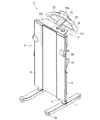
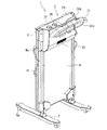
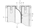
図1は本発明の第1実施形態に係る縦型ズボンプレッサーの正面側から見た斜視図であり、図2は本縦型ズボンプレッサーの背面側から見た斜視図であり、図3は本縦型ズボンプレッサーの上部の縦断面図である。 FIG. 1 is a perspective view seen from the front side of the vertical trouser press according to the first embodiment of the present invention, FIG. 2 is a perspective view seen from the back side of the vertical trouser press, and FIG. It is a longitudinal cross-sectional view of the upper part of a vertical trouser presser.
図1〜図3に示すように、第1実施形態に係る縦型ズボンプレッサー1は、ズボンをプレスするズボンプレッサー部2と、ジャケットなどの衣類の脱臭を行う脱臭装置部3を備える。
As shown in FIGS. 1 to 3, the vertical trouser press 1 according to the first embodiment includes a
ズボンプレッサー部2は、縦型で全体として矩形をなし、第1のプレス板としての台板を構成する固定板4と、この固定板4にヒンジ継手5により開閉自在にヒンジ結合された第2のプレス板としての可動板6とを有し、立てた状態で使用し、ストッパー付きキャスター7aを備える脚部7が、固定板4の下端に設けられる。
The
また、固定板4と可動板6との間には可撓性を有する1枚のプレスシート8が介装される。
Further, a
さらに、固定板4と可動板6の少なくともいずれか一方、例えば固定板4には、そのほぼ全面に設けられた蛇行状のヒータ収容凹部4aに加熱源として線状のヒータ9が収容される。また、固定板4にはヒータ9を覆うように均熱板10が設けられ、さらに、均熱板10を覆うように抑え布11が全面に渡り設けられる。
Further, at least one of the
一方、可動板6には全面に渡りクッション体12が設けられ、さらに、クッション体12を覆うように抑え布13が設けられる。
On the other hand, the
また、固定板4には、クランプ用のレバー14が設けられ、このレバー14は可動板6に設けられた係合部材6aに係脱し、可動板6の固定板4への圧接と、固定板4からの開放を可能にする。
The
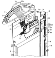
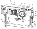
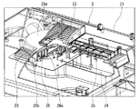
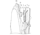
図4ないし図7に示すように、ズボンプレッサー部2の上部背面側には、上記脱臭装置部3が設けられる。
As shown in FIGS. 4 to 7, the
脱臭装置部3は、装置筐体21を備え、この装置筐体21の上端近傍に吸気口22、下部寄りに排気口23が設けられ、さらに、吸気口22、排気口23を連通するほぼコ字状をなす通風路24が設けられ、吸気口22は排気口23の上方に設けられる。
The
また、この通風路24には、吸気口22側(上流側)に脱臭手段25が設けられ、脱臭手段25の排気口23側(下流側)に、脱臭手段25に空気を流し、モータとファンからなる送風機26が設けられる。
Further, the
従って、送風機26の回転によって、吸気口22から通風路24に吸込まれ、ジャケットに付着した埃や汗などの臭いを含んだ空気は、脱臭手段25で、除塵され、脱臭され、送風機26を介して、排気口23から排気される。
Therefore, the air containing the odor such as dust and sweat sucked into the
本発明における脱臭は、脱臭に限らず消臭を含む意味に用いる。 The deodorization in the present invention is not limited to deodorization but is used to mean deodorization.
脱臭手段25は脱臭フィルタ25aからなる。脱臭手段25は脱臭フィルタ25aと、この脱臭フィルタ25aの風上側に設けられ除塵するプレフィルタ25bが一体的に構成されるのが好ましい。脱臭フィルタ25aは通気性を有するメッシュ体あるいは多孔質体に脱臭化学物質を担持したものを用いるのが好ましい。
The deodorizing means 25 includes a
送風機26は、ケーシング26aに収容された小型で扁平な遠心ファン26bと、ケーシング26a外に設けられ回転軸を介して遠心ファン26bを回転駆動するモータ26cからなる。
The
通風路24、脱臭手段25、送風機26は、いずれも装置筐体21に立てた状態で収容し、装置筐体21の薄形化を図っている。
The
また、装置筐体21の上面をなすトレーカバー21aの一側には、ヒータ9の通電を制御するヒータ用ゼンマイタイマツマミ28と、送風機26の回転時間を制御する送風機用ゼンマイタイマツマミ29が設けられる。
In addition, on one side of the
さらに、トレーカバー21aの他側には、小物類を収容する収納凹部21bが設けられ、この収納凹部21bには開閉自在に蓋体21cが設けられ、さらに、収納凹部21bの側部上端には、収納凹部21bに収容される携帯電話に充電するための給電コードの挿通孔21dが設けられる。さらに、収納凹部21bの側部近傍には、充電に用いる電源コンセント30が設けられる。
Furthermore, the other side of the
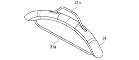
さらに、脱臭装置部3の背面上部には、衣類保持部材31が設けられる。
Furthermore, a
図4および図8に示すように、この衣類保持部材31は、ジャケットなどを掛けるのに適する例えばハンガーからなる。
As shown in FIGS. 4 and 8, the
この衣類保持部材(ハンガー)31には、下方に延びて設けられ、ズボンを掛けるのに適するズボン掛け31aと、衣類保持部材31の上部に突出し、ジャケットなど衣類の襟が掛かり、衣類の胸元が開いた状態で吸気口22および排気口23に対向するように位置決めするほぼヘ字状の位置決め部材31bであるハンガー上とが設けられる。
The garment holding member (hanger) 31 extends downward and is provided with a
衣類保持部材31は、衣類が掛けられ、わずかに湾曲し、かつこの湾曲の凹面側がズボンプレッサー部2に対向するように装置筐体21に取付けられる。
The
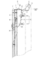
また、図5および図9に示すように、衣類保持部材31は、取付部材32によって、装置筐体21から、すなわち吸気口22および排気口23から離間した状態で、装置筐体21に取付けられる。
Further, as shown in FIGS. 5 and 9, the
衣類保持部材31の取付けは、衣類保持部材31に設けた取付凹部31cに取付部材32の一端32aを嵌合し、他端32bを装置筐体21に設けた取付凹部21eに嵌合することで行われる。
The attachment of the
衣類保持部材31は、この衣類保持部材31にジャケットなどが掛けられた場合、ジャケットの内面背中側と吸気口22および排気口23間に空間Gが空くような間隔で取付られる。
When a jacket or the like is hung on the
なお、衣類保持部材はズボンプレッサー部に予め一体に取付けて置いてもよいし、使用時に別体の衣類保持部材をズボンプレッサー部に一体的に取付けてもよい。 The clothing holding member may be integrally attached to the trouser presser in advance, or a separate clothing holding member may be integrally attached to the trouser presser during use.
衣類保持部材(ハンガー)31は、脚部7の後端7bより後方に突出することがないよう設計している。
The clothing holding member (hanger) 31 is designed not to protrude rearward from the
次に本第1実施形態のズボンプレッサーの使用方法について説明する。 Next, the usage method of the trouser press of this 1st Embodiment is demonstrated.
ズボンを単独でプレス作業する場合は以下のようにして行う。 When pressing trousers independently, the procedure is as follows.
図10は本縦型ズボンプレッサーのズボンプレッサー部の使用方法を示す説明図であり、脱臭装置部を省略して示す。 FIG. 10 is an explanatory view showing a method of using the trouser press portion of the vertical trouser press, and the deodorizing device portion is omitted.
図10によりズボンのズボンプレッサー部へのセット方法について説明する。 A method of setting the trousers on the trouser presser will be described with reference to FIG.
レバー14を上げて可動板6を開き、プレスシート8を固定板4側に寄せる(図10(a))。
The
ズボンのすそ部を下方までおろし、ズボンのたるみを整え(図10(b))、ズボンの片方を持ち上げてから、プレスシート8をズボン側に寄せ(図10(c))、持ち上げたズボンをプレスシート8を挟むように降ろし、再度ズボンのたるみを整え(図10(d))、可動板6を閉じ、固定板4に設けられたレバー14を可動板6に設けられた係合部材6aに係合させ、可動板6によりプレス圧を加えた状態でズボンを固定板4と可動板6間に保持する。
Lower the bottom of the trousers downward, adjust the slack of the trousers (FIG. 10 (b)), lift one side of the trousers, bring the
しかる後、図6に示すヒータ用ゼンマイタイマツマミ28を回して所望の時間ヒータ9に通電する。
Thereafter, the heater
ズボンは固定板4に収容されたヒータ9の加熱作用と、可動板6に収容されたクッション体12の押圧によるプレス作用を受けて、加熱プレスされる。ズボンは、ヒータ9により100℃以下、例えば70℃〜90℃に加熱され、クッション体12等によりプレスされ、ヒータ9の加熱時間は図示しないタイマにより制限され、約10分〜15分程度で加熱プレス作業が終了する。
The trousers are heated and pressed by the heating action of the heater 9 accommodated in the fixed
ズボンのプレス作業と同時にジャケットの脱臭作業を行う場合は以下のようにして行う。 When deodorizing the jacket at the same time as pressing the trousers, it is performed as follows.
例えば、上記と同様にして、ズボンを可動板6と固定板4間に保持した後、ジャケットを図9および図11に示すように、衣類保持部材31にかける。
For example, in the same manner as described above, after holding the pants between the
ジャケットは位置決め部材31bに襟が掛かって位置決めされ、衣類の胸元が開いた状態で吸気口22および排気口23に対向し、吸気口22および排気口23とジャケットの内面背中側間には、空間Gが設けられる。
The jacket is positioned with a collar on the
しかる後、図6に示すヒータ用ゼンマイタイマツマミ28を回して所望の時間ヒータ9に通電し、さらに、送風機用ゼンマイタイマツマミ29を回して所望の時間、送風機26に通電する。
Thereafter, the heater
送風機26に通電されると、送風機26は回転し、図7および図9に示すように、吸気口22はジャケットに沿って上昇する空気を吸込み、吸込まれた空気は、通風路24を介して、脱臭手段25に達し、プレフィルタ25bで除塵され、脱臭フィルタ25aで脱臭されて、さらに、送風機26を介して、排気口23からジャケットに向かって排出される。
When the
排気口23から排出される空気は、吸気口22から吸込まれ、通風路24を通過する間にヒータ9により加熱された固定板4を介して加熱される。
Air exhausted from the
衣類の胸元が開いた状態で吸気口22および排気口23に対向し、吸気口22および排気口23とジャケットの内面背中側間には、空間Gが設けられているので、加熱された排気は、ジャケットに沿って上昇し、ジャケットに含まれる臭気を含んで再び吸気口22に吸込まれる。
Since the chest of clothing is open, it faces the
再び吸気口22に吸込まれ、臭気を含んだ空気は、プレフィルタ25bで除塵され、脱臭フィルタ25aで脱臭され、送風機26を介して、排気口23からジャケットに向かって排出され、この循環を繰り返す。
Drawn into the
上記脱臭過程において、吸気口22からズボンプレッサー部2の背面に設けた通風路24に吸込まれた空気は、別個のヒータを設けることなく、通風路24を通過する間にヒータ9により加熱された固定板4を介して加熱され、脱臭効果が促進され、また、加熱された空気は、吸気口22がズボンプレッサー部2の背面の上部に設けられ、さらに、吸気口22が排気口23の上方に設けられるので、排気口23から排出された空気は、ジャケットに沿って、臭気を多く含むジャケットの上部、すなわち肩部まで確実に上昇し、肩部をはじめジャケットに含まれる臭気を確実に脱臭する。
In the deodorization process, air is sucked into the
また、衣類保持部材31は、吸気口22および排気口23と、衣類との間に空間Gが空くように配置されるので、排気口23から排出され加熱された排気は、ジャケットに沿って、肩部まで確実に上昇する。
Moreover, since the
さらに、脱臭手段25は上流側に吸気中のごみを除去するプレフィルタ25bを設け、このプレフィルタ25bの下流側に脱臭フィルタ25aを一体的に設けるので、塵埃により脱臭フィルタ25aが目詰りすることなく、長寿命になり、保守点検も容易である。
Further, the deodorizing means 25 is provided with a
また、衣類保持部材31は、位置決め部材31bを備え、衣類保持部材31がわずかに湾曲し、かつこの湾曲の凹面側がズボンプレッサー部2に対向するので、ジャケットは位置決め部材31bに襟が掛かって位置決めされ、ジャケットの胸元が開いた状態になり、加熱された排気をジャケットに沿って確実に上昇させることができる。
Moreover, since the
さらに、衣類保持部材31は、この衣類保持部材31の下方に、ズボン掛け部31aを備えるので、ズボンプレッサー部2を用いない脱臭装置部3の単独使用によって、ズボンの脱臭を行うことができる。なお、この脱臭装置部を単独で使用時、脱臭効果を向上させるために、送風機用ゼンマイタイマツマミ29に制御されるヒータを通風路に設けておいてもよい。
Furthermore, since the
本第1実施形態の縦型ズボンプレッサーによれば、ズボンのプレスができるとともに、ジャケットその他衣類の脱臭を行うことできる縦型ズボンプレッサーが実現する。 According to the vertical trouser press of the first embodiment, a vertical trouser press capable of pressing trousers and deodorizing jackets and other clothing is realized.
また、本発明の第2実施形態に係る縦型ズボンプレッサーについて説明する。 A vertical trouser press according to a second embodiment of the present invention will be described.
本第2実施形態は、第1実施形態の吸気口に、通風路が設けられた取付部材の一端が取付けられて通気的に接続され、取付部材の他端は吸気口が設けられた衣類保持部材に取付られて通気的に連通される。 This second embodiment is the air intake port of the first embodiment, is attached one end of the mounting member air passage is provided vented connected, the other end of the mounting member air intake port is provided Attached to the clothing holding member and communicated in a breathable manner.
例えば、図12に示すように、第2実施形態に係る型ズボンプレッサー1Aは、ズボンプレッサー部2と、ジャケットなどの衣類の脱臭を行う脱臭装置部3Aを備える。
For example, as shown in FIG. 12, a pattern trouser press 1 </ b> A according to the second embodiment includes a
脱臭装置部3Aは、上方に開口した吸気口22Aに一端32A1が取付けられた取付部材32Aを備え、この取付部材32Aの他端32A2には、衣類保持部材31Aが取付けられる。
The
取付部材32Aの内部には、通風路24の一部をなす取付部材側通風路24Aが設けられ、衣類保持部材31Aの下部側には、衣類保持部材側吸気口22Aが設けられる。
Inside the mounting
従って、衣類保持部材側吸気口22Aは、取付部材側通風路24Aを介して衣類保持部材側吸気口22Aに通気的に連通される。
Therefore, the garment retaining member side
これにより、衣類保持部材側吸気口22Aが、ジャケットの肩部近傍に設けられるので、加熱された排気は、ジャケットに沿って、臭気を多く含む肩部まで確実に上昇し、肩部をはじめジャケットに含まれる臭気をより確実に脱臭する。
Thus, the garment retaining member side
臭気を多く空気は、衣類保持部材側吸気口22A、取付部材側通風路24A、通風路24を介して、脱臭手段25で除塵、脱臭されて、排気口23からジャケットに向けて排気される。
Many air odor garment retention member side
本第2実施形態の縦型ズボンプレッサーによれば、ズボンのプレスができるとともに、ジャケットその他衣類の脱臭を行うことができる縦型ズボンプレッサーが実現する。 According to the vertical trouser press of the second embodiment, a vertical trouser press capable of pressing trousers and deodorizing jackets and other clothing is realized.
他の構成は図5に示す縦型ズボンプレッサーと異ならないので、同一符号を付して説明は省略する。 Since the other configuration is not different from the vertical trouser press shown in FIG.
なお、上記第1実施形態および第2実施形態では、通風路および、この通風路内に設けられた脱臭手段と送風機をズボンプレッサー部の背面に設ける例で説明したが、通風路を脚部まで延長し、脱臭手段および送風機を脚部上に設けるなど、必ずしもプレッサー部の背面に設ける必要はない。 In addition, in the said 1st Embodiment and 2nd Embodiment, although it demonstrated by the example which provides the ventilation path and the deodorizing means and air blower which were provided in this ventilation path in the back surface of a trouser press part, a ventilation path is extended to a leg part. It is not always necessary to provide the deodorizing means and the blower on the leg portion, such as extending on the leg portion.
1 縦型ズボンプレッサー
2 ズボンプレッサー部
3 脱臭装置部
4 固定板
4a ヒータ収容凹部
5 ヒンジ継手
6 可動板
6a 係合部材
7 脚部
7a キャスター
7b 後端
8 プレスシート
9 ヒータ
10 均熱板
11 抑え布
12 クッション体
13 抑え布
14 レバー
21 装置筐体
21a トレーカバー
21b 収納凹部
21c 蓋体
21d 挿通孔
21e 取付凹部
22 吸気口
23 排気口
24 通風路
25 脱臭手段
25a 脱臭フィルタ
25b プレフィルタ
26 送風機
26a ケーシング
26b 遠心ファン
26c モータ
28 ヒータ用ゼンマイタイマツマミ
29 送風機用ゼンマイタイマツマミ
30 電源コンセント
31 衣類保持部材
31a ズボン掛け
31b 位置決め部材
31c 取付凹部
32 取付部材
32a 一端
32b 他端
G 空間
DESCRIPTION OF SYMBOLS 1
Claims (9)
前記ズボンプレッサー部の一方の面に脱臭装置部が設けられ、
この脱臭装置部は、
吸気口および排気口と、
前記吸気口と前記排気口を連通する通風路と、
この通風路内に設けられた脱臭手段と、
前記通風路内に設けられ、前記吸気口から吸気し前記排気口から排気して、前記脱臭手段に空気を流す送風機と、
保持された衣類が、前記排気口および前記吸気口に近接するように、取付部材により前記ズボンプレッサー部に配置される衣類保持部材とを備え、
前記送風機の回転により、前記衣類保持部材に保持された衣類と対向する前記吸気口から吸込まれた空気を前記脱臭手段で脱臭し、
前記排気口を介して前記衣類に向けて排気して、
前記衣類の脱臭を行う
ことを特徴とする縦型ズボンプレッサー。 A first press plate having one side as a press surface, and a second press plate having a press surface opposite to the press surface of the first press plate and provided openably and closably on the first press plate; Vertical trousers having a trouser presser portion including a heater provided on at least one of the first press plate and the second press plate, and a leg portion that brings the first press plate into a standing state. In the presser,
A deodorizing device is provided on one surface of the trouser press;
This deodorization unit is
Intake and exhaust ports,
A ventilation path communicating the intake port and the exhaust port;
Deodorizing means provided in the ventilation path;
A blower that is provided in the ventilation path, sucks air from the intake port, exhausts air from the exhaust port, and flows air to the deodorizing means;
Retained clothing, the so as to be close to the exhaust port and the intake port, and a garment retaining member disposed on the trouser press unit by the mounting member,
Wherein by rotation of the blower, the air sucked from the air suction port to the garment facing held in the garment retaining member deodorized in the deodorizing means,
Exhaust toward the clothing through the exhaust port,
A vertical trouser press that deodorizes the clothing.
Priority Applications (1)
| Application Number | Priority Date | Filing Date | Title |
|---|---|---|---|
| JP2008304290A JP5219081B2 (en) | 2008-11-28 | 2008-11-28 | Vertical trouser press |
Applications Claiming Priority (1)
| Application Number | Priority Date | Filing Date | Title |
|---|---|---|---|
| JP2008304290A JP5219081B2 (en) | 2008-11-28 | 2008-11-28 | Vertical trouser press |
Publications (2)
| Publication Number | Publication Date |
|---|---|
| JP2010125141A JP2010125141A (en) | 2010-06-10 |
| JP5219081B2 true JP5219081B2 (en) | 2013-06-26 |
Family
ID=42325926
Family Applications (1)
| Application Number | Title | Priority Date | Filing Date |
|---|---|---|---|
| JP2008304290A Expired - Fee Related JP5219081B2 (en) | 2008-11-28 | 2008-11-28 | Vertical trouser press |
Country Status (1)
| Country | Link |
|---|---|
| JP (1) | JP5219081B2 (en) |
Families Citing this family (1)
| Publication number | Priority date | Publication date | Assignee | Title |
|---|---|---|---|---|
| JP5502609B2 (en) * | 2010-06-15 | 2014-05-28 | 株式会社東芝 | Vertical trouser press |
Family Cites Families (9)
| Publication number | Priority date | Publication date | Assignee | Title |
|---|---|---|---|---|
| JPS5646717Y2 (en) * | 1977-06-06 | 1981-10-31 | ||
| JP3250294B2 (en) * | 1993-02-03 | 2002-01-28 | 松下電器産業株式会社 | Trouser press |
| JPH0677653U (en) * | 1993-04-12 | 1994-11-01 | 西武電機工業株式会社 | Trouser press stand |
| JPH08126798A (en) * | 1994-10-31 | 1996-05-21 | Matsushita Seiko Co Ltd | Maintenance device for clothes |
| JPH09135995A (en) * | 1995-11-15 | 1997-05-27 | Matsushita Electric Ind Co Ltd | Clothing drying system with wrinkle removing and deodorizing functions |
| JP3821891B2 (en) * | 1996-12-12 | 2006-09-13 | 金澤工業株式会社 | Trouser press |
| JP4268265B2 (en) * | 1999-06-09 | 2009-05-27 | 積水化学工業株式会社 | Storage room for clothes, etc. |
| JP2001334100A (en) * | 2000-05-26 | 2001-12-04 | Nisshin Kogyo Co Ltd Saitama Plant | Dehumidification machine with drying room |
| JP4279154B2 (en) * | 2004-01-09 | 2009-06-17 | 東芝コンシューマエレクトロニクス・ホールディングス株式会社 | Clothing press |
-
2008
- 2008-11-28 JP JP2008304290A patent/JP5219081B2/en not_active Expired - Fee Related
Also Published As
| Publication number | Publication date |
|---|---|
| JP2010125141A (en) | 2010-06-10 |
Similar Documents
| Publication | Publication Date | Title |
|---|---|---|
| KR20120066549A (en) | Clothing dryer | |
| TW200716810A (en) | Drum type drying and washing machine | |
| JP2005040580A (en) | Clothes dryer and method of controlling the same | |
| KR20150085728A (en) | Clothes treating apparatus with heat pump | |
| US11629452B2 (en) | Clothes treatment apparatus | |
| WO2018059366A1 (en) | Clothing treating device | |
| CN114867902A (en) | Clothes treating device | |
| JP5292222B2 (en) | Clothes dryer | |
| JP5219081B2 (en) | Vertical trouser press | |
| KR20190082720A (en) | Fabric treating apparatus | |
| CN113272492A (en) | Clothes treating device | |
| EP2876200B1 (en) | Laundry dryer apparatus | |
| CN102560991B (en) | Laundry drying processor | |
| JP5051917B2 (en) | Vertical trouser press | |
| KR100994080B1 (en) | Dry device of food-waste | |
| JPH1189700A (en) | Clothes hanger | |
| JP3717689B2 (en) | Bedding dryer | |
| CN114846196A (en) | Clothes treating device | |
| TW200307074A (en) | Washing machine with dryer functions | |
| CN114846197A (en) | Clothes treating device | |
| KR20200004168A (en) | Drying method to prevent water-drop inside the door of multi-function storage system and multi-function storage system performing the same | |
| CN2904800Y (en) | Shoe box having dehumidification function | |
| KR200264785Y1 (en) | Cloth dryer | |
| KR102324213B1 (en) | Clothes care appartus having a clothes cover for clothes care | |
| KR102443322B1 (en) | Fabric treating apparatus |
Legal Events
| Date | Code | Title | Description |
|---|---|---|---|
| RD04 | Notification of resignation of power of attorney |
Free format text: JAPANESE INTERMEDIATE CODE: A7424 Effective date: 20100422 |
|
| A621 | Written request for application examination |
Free format text: JAPANESE INTERMEDIATE CODE: A621 Effective date: 20101213 |
|
| RD01 | Notification of change of attorney |
Free format text: JAPANESE INTERMEDIATE CODE: A7421 Effective date: 20111215 |
|
| A977 | Report on retrieval |
Free format text: JAPANESE INTERMEDIATE CODE: A971007 Effective date: 20120525 |
|
| A131 | Notification of reasons for refusal |
Free format text: JAPANESE INTERMEDIATE CODE: A131 Effective date: 20120626 |
|
| A521 | Written amendment |
Free format text: JAPANESE INTERMEDIATE CODE: A523 Effective date: 20120709 |
|
| TRDD | Decision of grant or rejection written | ||
| A01 | Written decision to grant a patent or to grant a registration (utility model) |
Free format text: JAPANESE INTERMEDIATE CODE: A01 Effective date: 20130205 |
|
| A61 | First payment of annual fees (during grant procedure) |
Free format text: JAPANESE INTERMEDIATE CODE: A61 Effective date: 20130227 |
|
| FPAY | Renewal fee payment (event date is renewal date of database) |
Free format text: PAYMENT UNTIL: 20160315 Year of fee payment: 3 |
|
| R150 | Certificate of patent or registration of utility model |
Ref document number: 5219081 Country of ref document: JP Free format text: JAPANESE INTERMEDIATE CODE: R150 Free format text: JAPANESE INTERMEDIATE CODE: R150 |
|
| S111 | Request for change of ownership or part of ownership |
Free format text: JAPANESE INTERMEDIATE CODE: R313115 |
|
| R350 | Written notification of registration of transfer |
Free format text: JAPANESE INTERMEDIATE CODE: R350 |
|
| S531 | Written request for registration of change of domicile |
Free format text: JAPANESE INTERMEDIATE CODE: R313531 |
|
| S533 | Written request for registration of change of name |
Free format text: JAPANESE INTERMEDIATE CODE: R313533 |
|
| R350 | Written notification of registration of transfer |
Free format text: JAPANESE INTERMEDIATE CODE: R350 |
|
| S111 | Request for change of ownership or part of ownership |
Free format text: JAPANESE INTERMEDIATE CODE: R313117 |
|
| S531 | Written request for registration of change of domicile |
Free format text: JAPANESE INTERMEDIATE CODE: R313531 |
|
| R350 | Written notification of registration of transfer |
Free format text: JAPANESE INTERMEDIATE CODE: R350 |
|
| S111 | Request for change of ownership or part of ownership |
Free format text: JAPANESE INTERMEDIATE CODE: R313117 |
|
| R350 | Written notification of registration of transfer |
Free format text: JAPANESE INTERMEDIATE CODE: R350 |
|
| R250 | Receipt of annual fees |
Free format text: JAPANESE INTERMEDIATE CODE: R250 |
|
| LAPS | Cancellation because of no payment of annual fees |