本発明に係る遊技機は、手段1として、
所定の受球位置で遊技球を受容し、該受球位置から所定距離をおいた排球位置まで該遊技球を移動させて、該排球位置に形成された排出口に該遊技球を排出するように動作する可動体を備える役物が遊技領域に配置された遊技機であって、
前記遊技球が前記排球位置にきたときに、該遊技球を前記可動体と前記排出口とを跨ぐ体勢に保持しつつ排出するように誘導する球進路誘導手段が設けられていることを特徴とする。
Game machine according to the present invention, as a means 1,
A game ball is received at a predetermined ball receiving position, the game ball is moved to a ball discharging position at a predetermined distance from the ball receiving position, and the game ball is discharged to a discharge port formed at the ball discharging position. A game machine in which a game object having a movable body that is operated in a game area is arranged,
When the game ball comes to the ball discharge position, a ball course guiding means is provided for guiding the game ball to be discharged while being held in a posture straddling the movable body and the discharge port. To do.
本発明において、「役物」とは、遊技領域内を流下する遊技球の運動に何らかの変化を付与し得るように構成された任意の構成物を意味し、入賞口等の入賞機構を備えるものと備えないものとをいずれも含意する。
In the present invention, the “act” means any component configured to be able to give some change to the motion of the game ball flowing down in the game area, and has a winning mechanism such as a winning opening. And the things that do not have.
上記手段1の構成によれば、例えば可動体が排球位置まで移動してきて何らかの固定構造物にバウンドするような構造となっている場合でも、遊技球が排出される際に球進路誘導手段により遊技球が可動体と排出口とを跨ぐ体勢に保持されること、換言すれば、遊技球が可動体と排出口とを跨ぐ体勢に保持されるようにその進路が誘導されつつ排出されることで、該可動体が遊技球によりロックされて排球位置に保持され、バウンド動作が抑止される。即ち、遊技球が、排出される際にそのまま無条件に排出されるのではなく、可動体と排出口とを跨ぐように位置して該可動体を排球位置にロックする「かんぬき」のように機能する。このように遊技球自体に可動体の動きを抑止するように機能させながら該遊技球を排出する構成とすることで、可動体の動きを抑止するための機構を別に必要とすることがなく、したがって簡略な構成によって可動体に所望の動作を容易かつ確実に行わせることが可能な役物とすることができる。
According to the configuration of the means 1, for example, even when the movable body moves to the ball-discharging position and bounces to some fixed structure, the game is guided by the ball course guiding means when the game ball is discharged. The ball is held in a posture that straddles the movable body and the discharge port, in other words, the course is guided and discharged so that the game ball is held in a posture that straddles the movable body and the discharge port. The movable body is locked by the game ball and is held at the ball discharging position, and the bounding action is suppressed. In other words, when a game ball is discharged, it is not discharged unconditionally as it is, but it is positioned so as to straddle the movable body and the discharge port, as in “Kanuki” that locks the movable body to the ball discharge position. Function. In this way, the game ball itself is configured to discharge the game ball while functioning so as to suppress the movement of the movable body, so that there is no need for a separate mechanism for suppressing the movement of the movable body, Therefore, it can be set as the accessory which can make a movable body perform desired operation | movement easily and reliably by simple structure.
また、本発明に係る遊技機は、手段2として、手段1の遊技機において、
前記球進路誘導手段が、前記可動体から漸次遠ざかる勾配を有する傾斜に沿って遊技球を誘導するものであることを特徴とする。
Further, the gaming machine according to the present invention is a gaming machine of means 1 as means 2,
The ball course guiding means guides the game ball along an inclination having a gradient gradually moving away from the movable body.
上記手段2の構成によれば、遊技球が傾斜に沿って誘導されながら排出されることで、排出される際に無条件に排出されるのではなく前記可動体と前記排出口とを跨ぐ体勢に容易かつ確実に保持されるようになっている一方、傾斜によって容易かつ確実に排出されるようになっている。即ち、可動体のバウンド動作の抑止と遊技球の排出とがいずれも容易かつ確実になされる構成となっている。
また、球進路誘導手段の構成としては、例えば、弾性を有する突起物により遊技球を一時的に可動体と排出口とを跨ぐ体勢に保持し、該突起物が弾性変形することによって遊技球を排出するように誘導するようにした構成なども可能であるが、上記手段2の構成によれば、勾配を適宜な程度に設定することにより、遊技球を前記可動体と前記排出口とを跨ぐ体勢に保持しつつ排出するように誘導する球進路誘導手段を構成することができ、したがって、上記傾斜を有する構造物だけで球進路誘導手段を構成できるため球進路誘導手段の構成をより簡略化できるとともに、劣化等も比較的に少ない球進路誘導手段とすることができる。
According to the configuration of the means 2, the game ball is discharged while being guided along the inclination, so that the posture straddling the movable body and the discharge port is not unconditionally discharged when discharged. While being easily and reliably held, it is easily and reliably discharged by the inclination. In other words, both the restraining of the bounding motion of the movable body and the discharge of the game ball are easy and reliable.
In addition, as the configuration of the ball course guiding means, for example, the game ball is temporarily held in a posture straddling the movable body and the discharge port by an elastic projection, and the projection ball is elastically deformed to thereby change the game ball. Although the structure etc. which guide | induced so that it may discharge | emit are also possible, according to the structure of the said means 2, a game ball is straddled across the said movable body and the said discharge port by setting a gradient to an appropriate grade. It is possible to configure a ball course guiding means that guides the player to discharge while holding the body. Therefore, since the ball course guiding means can be configured only by the structure having the above-described inclination, the configuration of the ball course guiding means is further simplified. In addition, it is possible to provide a ball course guiding means with relatively little deterioration.
また、本発明に係る遊技機は、手段3として、手段1または手段2の遊技機において、
前記遊技球が前記排球位置にきたときに前記可動体に係合して該可動体を当該位置にロックし、該可動体が別の遊技球を受容すると前記可動体から離脱してロックを解除する係合手段を備えることを特徴とする。
Further, the gaming machine according to the present invention is a gaming machine of means 1 or means 2 as means 3,
When the game ball reaches the ball discharge position, it engages the movable body and locks the movable body at the position, and when the movable body receives another game ball, it is detached from the movable body and unlocked. It is characterized by including an engaging means.
前述したように、遊技球が前記排球位置にきたときは可動体が遊技球によりロックされて排球位置に保持されるようになっているが、上記手段3のような係合手段を設けることで、該遊技球が排出された後も、別の遊技球を受容するまでの間、可動体の動きを抑止しておくことができる。
As described above, the movable body is locked by the game ball when the game ball reaches the ball discharge position, and is held at the ball discharge position. Even after the game ball is discharged, the movement of the movable body can be suppressed until another game ball is received.
また、本発明に係る遊技機は、手段4として、手段1から手段3のいずれかの遊技機において、
前記受球位置が排球位置よりも上方に位置し、可動体が遊技球の重さにより該受球位置から排球位置まで移動する構成となっていることを特徴とする。
A gaming machine according to the present invention is a gaming machine according to any one of the means 1 to 3, as the means 4.
The ball receiving position is located above the ball discharging position, and the movable body is configured to move from the ball receiving position to the ball discharging position by the weight of the game ball.
上記手段4の構成によれば、遊技球の重さを利用して可動体を動作させる構成となっていることで、可動体を動作させるための動力源や該動力源による動力を伝達する機構を設ける必要がなく、そのぶん可動体をより簡略に構成することができる。
According to the configuration of the means 4, the power source for operating the movable body and the mechanism for transmitting the power from the power source by operating the movable body using the weight of the game ball. Therefore, the movable body can be configured more simply.
また、本発明に係る遊技機は、手段5として、手段4の遊技機において、
前記可動体が、軸回りに回動することにより受球位置と排球位置との間を移動する構成を有し、受球位置において回動方向側に重心が偏った体勢で遊技球を受容する遊技球保持部を有することを特徴とする。
Moreover, the gaming machine according to the present invention is a gaming machine of means 4 as means 5,
The movable body is configured to move between a ball receiving position and a ball discharging position by rotating around an axis, and receives a game ball with a posture in which the center of gravity is biased toward the rotating direction at the ball receiving position. It has a game ball holding part.
上記手段5の構成によれば、回動方向側に重心が偏った体勢で遊技球を受容する構成とすることで、遊技球の重さが回動方向側にかかって可動体が回動方向側に確実かつ容易に動作するようにすることができる。
According to the configuration of the means 5, the game ball is received with a posture in which the center of gravity is biased toward the rotation direction side, so that the weight of the game ball is applied to the rotation direction side and the movable body is rotated in the rotation direction. Can be operated reliably and easily to the side.
また、本発明に係る遊技機は、手段6として、手段5の遊技機において、
前記遊技球保持部が、回動軸へむけて陥入する凹形状を有し、その内壁が、回動方向側と反対側から該回動方向側へかけて湾曲面状に延びる形状となっていることを特徴とする。
Moreover, the gaming machine according to the present invention is a gaming machine of means 5 as means 6,
The game ball holding portion has a concave shape that is recessed toward the rotation axis, and an inner wall of the game ball holding portion extends in a curved surface shape from the opposite side to the rotation direction side. It is characterized by.
上記手段6の構成によれば、湾曲面状に延びる内壁に沿って遊技球が回動方向側へ案内され、これにより可動体が回動方向側により確実かつ容易に動作することができる。
According to the configuration of the means 6, the game ball is guided to the rotation direction side along the inner wall extending in the curved surface shape, whereby the movable body can operate reliably and easily on the rotation direction side.
また、本発明に係る遊技機は、手段7として、手段4から手段6のいずれかの遊技機において、
一方端が前記可動体に回動自在に軸支され、他方端が受球位置から排球位置へ落下し得る揺動体を備えることを特徴とする。
In addition, the gaming machine according to the present invention is the gaming machine according to any one of the means 4 to 6, as the means 7,
One end is pivotally supported by the movable body, and the other end is provided with a rocking body that can fall from the ball receiving position to the ball discharging position.
上記手段7の構成によれば、遊技球の重さを利用して可動体を動作させるのに加えて、揺動体の自由端が落下する動作を利用することで、可動体をより効果的に動作させることができる。
According to the configuration of the means 7, in addition to operating the movable body using the weight of the game ball, the movable body can be more effectively used by utilizing the movement of the free end of the swinging body falling. It can be operated.
また、本発明に係る遊技機は、手段8として、手段7の遊技機において、
前記揺動体を可動体に対し所定の角度をなす体勢に保持するスペーサを備えることを特徴とする。
Further, the gaming machine according to the present invention is a gaming machine of means 7 as means 8,
A spacer is provided for holding the rocking body in a posture that forms a predetermined angle with respect to the movable body.
上記手段8の構成によれば、揺動体が可動体に対し所定の角度をなす体勢、即ち、可動体に重合する体勢ではなく可動体から所定の角度だけ離間した体勢に保持されることで、自由端がより容易かつ確実に落下することができるようになっている。
According to the configuration of the means 8, the swinging body is held at a predetermined angle with respect to the movable body, that is, held at a posture separated from the movable body by a predetermined angle instead of being superimposed on the movable body. The free end can be more easily and reliably dropped.
また、本発明に係る遊技機は、手段9として、手段1から手段8のいずれかの遊技機において、
前記役物が、遊技球を外部に排出する毎に、複数の異なる外部排出位置に交互に振り分けるようにして排出する構成を有し、
遊技球が上記複数の外部排出位置のうちのいずれから排出されたかに応じて、遊技者にとっての有利さの度合いが異なる複数の遊技状態に交互に移行するように構成されていることを特徴とする。
The gaming machine according to the present invention is a gaming machine according to any one of means 1 to 8, as means 9.
Each time the game object is discharged to the outside, it has a configuration in which it is discharged in such a manner that it is alternately distributed to a plurality of different external discharge positions,
The game ball is configured to alternately shift to a plurality of game states having different degrees of advantage for the player depending on which of the plurality of external discharge positions is discharged. To do.
役物が遊技球を振り分ける機能を有し、この振り分けに応じて遊技状態が移行するように構成されている場合、例えば役物に前記のようなバウンド動作が生じると、役物の可動体が所定の動作を行った後にバウンドにより動作前の位置まで戻ってしまい、その結果、上記振り分けが秩序どおりに機能せず遊技状態が正しく移行しなくなって、遊技者にとって有利あるいは不利な遊技状態が不適正に継続するといった事態を生じることがある。ところが、上記手段9においては、前述の通りバウンド動作が抑止される構成とした手段1ないし手段8に係る役物を備える構成となっているので、可動体が所定の動作を行った後に動作前の位置まで戻ることがなく上記振り分けが秩序どおりに機能し、したがって遊技状態が適正に移行するようになっている。
In the case where the accessory has a function of distributing the game balls and the game state is shifted in accordance with the distribution, for example, when the above-described bounce operation occurs in the accessory, the movable object moves. After performing a predetermined action, it returns to the position before the action due to the bounce, and as a result, the above-mentioned sorting does not function in order and the gaming state does not shift correctly, and the gaming state that is advantageous or disadvantageous for the player is disadvantageous. It may happen that it continues properly. However, since the means 9 is provided with the accessory according to means 1 to means 8 configured to suppress the bound movement as described above, before the movable body performs a predetermined operation, the operation is performed. The above-mentioned sorting functions in an orderly manner without returning to the position of the game, so that the gaming state is appropriately shifted.
以下、本発明の最良の形態について、図面を参照して詳述する。但し、本発明の実施に際しては、本発明の主旨から逸脱しない限り適宜部分改変可能である。
Hereinafter, the best mode of the present invention will be described in detail with reference to the drawings. However, in carrying out the present invention, it is possible to make partial modifications as appropriate without departing from the gist of the present invention.
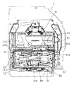
(パチンコ機の正面構成)
図1は本実施形態のパチンコ機10の正面図であり、図2は外枠11に対して内枠12と前面枠セット14と、セット板400を開放した状態を示す斜視図である。(但し、図2では便宜上、遊技盤4面上の遊技領城内の構成〔釘、センター役物等〕を空白で示しているが、アウト口36は描いてある)。
(Front configuration of pachinko machine)
FIG. 1 is a front view of a pachinko machine 10 according to the present embodiment, and FIG. 2 is a perspective view showing a state in which an inner frame 12, a front frame set 14, and a set plate 400 are opened with respect to an outer frame 11. (However, in FIG. 2, for the sake of convenience, the configuration in the game castle on the four sides of the game board [nail, center character, etc.] is shown blank, but the out port 36 is drawn).
図1および図2に示すように、パチンコ機10は、当該パチンコ機10の外殻を形成する外枠11と、この外枠11の一側部に開閉可能に支持された内枠12とを備えている。外枠11は、木製の板材により全体として矩形状に構成され、小ネジ等の離脱可能な締結具により各板材が組み付けられている。なお、外枠11は、軽量化を図るために、樹脂やアルミニウム等の軽金属により構成されていてもよい。内枠12の開閉軸線はパチンコ機10の正面からみて遊技球発射ハンドル18の設置箇所の反対側(図1のパチンコ機10の左側)で上下に延びるように設定されており、この開閉軸線を軸心にして内枠12が前方側に十分に開放できるようになっている。また、内枠12は合成樹脂、具体的にはABS(アクリロニトリルーブタジエンースチレン)樹脂から成る。こうすることで、粘性が高く衝撃に強くでき、低コストで製造できるという利点が発揮される。
As shown in FIGS. 1 and 2, the pachinko machine 10 includes an outer frame 11 that forms an outer shell of the pachinko machine 10, and an inner frame 12 that is supported on one side of the outer frame 11 so as to be opened and closed. I have. The outer frame 11 is formed in a rectangular shape as a whole by a wooden plate material, and each plate material is assembled by a detachable fastener such as a small screw. The outer frame 11 may be made of light metal such as resin or aluminum in order to reduce the weight. The opening / closing axis of the inner frame 12 is set to extend vertically on the opposite side of the game ball launching handle 18 installation position (left side of the pachinko machine 10 in FIG. 1) as seen from the front of the pachinko machine 10. The inner frame 12 can be sufficiently opened to the front side with an axial center. The inner frame 12 is made of a synthetic resin, specifically, ABS (acrylonitrile-butadiene-styrene) resin. By doing so, the advantages of high viscosity and high impact resistance and low cost production are exhibited.
前面枠セット14及び内枠12の構成を、図1〜図4を用いて詳細に説明する。図3は、パチンコ機10の外枠11から前面枠セット14及び遊技盤4を取り外した状態を示す背面図であり、図4は、その背面からの斜視図である。
The configuration of the front frame set 14 and the inner frame 12 will be described in detail with reference to FIGS. 3 is a rear view showing a state in which the front frame set 14 and the game board 4 are removed from the outer frame 11 of the pachinko machine 10, and FIG. 4 is a perspective view from the rear.
前面枠セット14は、大別すると、その最下部に設けられた球受皿部分と、この球受皿部分よりも上側の範囲に形成される窓枠部分と、を備えている。内枠12は、左側の上下方向の開閉軸線を軸心にして外枠11に対して開閉自在に取り付けられ、後述する樹脂ベース20を備え、この樹脂ベース20の前側に前面枠セット14が取り付けられ、後側に遊技盤4が取り付けられている。
When roughly classified, the front frame set 14 includes a ball tray portion provided at the lowermost portion thereof, and a window frame portion formed in a range above the ball tray portion. The inner frame 12 is attached to the outer frame 11 so as to be openable and closable with the left-hand vertical opening / closing axis as the axis, and includes a resin base 20 to be described later. A front frame set 14 is attached to the front side of the resin base 20. The game board 4 is attached to the rear side.
上記球受皿部分は、上記前面枠セット14の下側部分に対してネジ等の締結具により固定されている。この球受皿部分の前面側には、下皿15と球抜きレバー17と遊技球発射ハンドル18と灰皿22とが設けられている。また、球受皿としての下皿15は、後述の上皿19が満タンになった場合等に排出口より排出される遊技球を停留する機能を有している。球抜きレバー17は、下皿15内の遊技球を抜くためのものであり、この球抜きレバー17を図1で左側に移動させることにより、下皿15の底面の所定箇所が開口され、下皿15内に停留された遊技球を下皿15の底面の開口部分を通して遊技者の持球貯留箱(ドル箱)に排出することができる。
The ball tray portion is fixed to a lower portion of the front frame set 14 with a fastener such as a screw. A lower plate 15, a ball release lever 17, a game ball launch handle 18, and an ashtray 22 are provided on the front side of the ball tray portion. In addition, the lower tray 15 as a ball receiving tray has a function of stopping a game ball discharged from the discharge port when an upper tray 19 described later becomes full. The ball removal lever 17 is for removing a game ball in the lower plate 15. By moving the ball removal lever 17 to the left in FIG. 1, a predetermined position on the bottom surface of the lower plate 15 is opened, The game ball stopped in the tray 15 can be discharged through the opening on the bottom surface of the lower tray 15 to the player's ball storage box (dollar box).
そして、遊技球発射ハンドル18は、下皿15よりも右方で手前側に突出するように配設されている。遊技者による遊技球発射ハンドル18の操作に応じて、遊技球発射装置38(図2及び図3)によって遊技球が遊技盤4の方へ打ち込まれるようになっている。遊技球発射装置38は、発射ソレノイドなどで構成されている。音出力口24は、前面枠セット14の左右上端部位置に設けられたスピーカ(図示略)からの音を出力するための出力口である。また、灰皿22は下皿15の左方に設けられている。灰皿22は左右方向(水平方向)の軸線を軸心にして回動(例えば前方側に向けて前回り)するように設けられている。
The game ball launching handle 18 is disposed so as to protrude to the front side on the right side of the lower plate 15. In response to the operation of the game ball launch handle 18 by the player, the game ball is driven toward the game board 4 by the game ball launch device 38 (FIGS. 2 and 3). The game ball launching device 38 is composed of a launching solenoid or the like. The sound output port 24 is an output port for outputting sound from a speaker (not shown) provided at the position of the upper left and right ends of the front frame set 14. The ashtray 22 is provided on the left side of the lower plate 15. The ashtray 22 is provided so as to rotate (for example, forward toward the front side) about the axis line in the left-right direction (horizontal direction).
なお、前面枠セット14は、その大部分が内枠12と同様、ABS樹脂にて成形されている。こうすることで、粘性が高く衝撃に強くでき、低コストで製造できる。特に、下皿15を形成する表面層と下皿15の奥方の前面パネル部分とを難燃性のABS樹脂にて成形している。このため、この部分は燃えにくくなっている。
Note that most of the front frame set 14 is formed of ABS resin in the same manner as the inner frame 12. By doing so, it is highly viscous and resistant to impact, and can be manufactured at low cost. In particular, the surface layer forming the lower plate 15 and the front panel portion at the back of the lower plate 15 are molded from flame-retardant ABS resin. For this reason, this part is hard to burn.
また、前面枠セット14は、図2に示すように、内枠12に対して開閉可能に取り付けられており、内枠12と同様、パチンコ機10の正面からみて左側に上下に延びる開閉軸線を軸心にして前方側に開放できるようになっている。しかも前面枠セット14は内枠12の外側壁(リブ)12b内に嵌まり込むようにして取り付けられている。つまり、この前面枠セット14の側面の少なくとも一部が内枠12の外側壁(リブ)12b内に嵌まり込むようにして取り付けられているので、内枠12と前面枠セット14との隙間から異物(針状あるいは薄板状等のものであって、具体的には針金、ピアノ線、セルロイド板等)を差し入れるなどの不正行為を防止できるようになっている。また、前面枠セット14は、内枠12と同様に、合成樹脂、具体的にはABS樹脂により構成されているので、粘性が高く衝撃に強くでき、低コストで製造できる。
As shown in FIG. 2, the front frame set 14 is attached to the inner frame 12 so as to be openable and closable. Like the inner frame 12, the front frame set 14 has an open / close axis extending vertically to the left when viewed from the front of the pachinko machine 10. It can be opened to the front side with an axial center. Moreover, the front frame set 14 is attached so as to fit into the outer wall (rib) 12 b of the inner frame 12. That is, since at least a part of the side surface of the front frame set 14 is attached so as to fit into the outer wall (rib) 12b of the inner frame 12, foreign matter (from the gap between the inner frame 12 and the front frame set 14) Such as a needle shape or a thin plate shape, specifically, a fraudulent act such as inserting a wire, piano wire, celluloid plate, etc.) can be prevented. Further, since the front frame set 14 is made of a synthetic resin, specifically, an ABS resin, like the inner frame 12, the front frame set 14 is highly viscous and resistant to impact, and can be manufactured at low cost.
一方、上記前面枠セット14の球受皿部分のうち上述の下皿15の上方位置には、遊技球の受皿としての上皿19(図1参照)が前面枠セット14と一体的に設けられている。この上皿19は、遊技球を一旦貯留し、一列に整列させながら遊技球発射装置38の方へ導出するための球受皿である。この上皿19も下皿15と同様、表面層が難燃性のABS樹脂にて成形される構成となっている。
On the other hand, an upper plate 19 (see FIG. 1) serving as a game ball receiving plate is provided integrally with the front frame set 14 at a position above the lower plate 15 in the ball receiving portion of the front frame set 14. Yes. The upper tray 19 is a ball receiving tray for temporarily storing the game balls and guiding them to the game ball launching device 38 while aligning them in a line. Similar to the lower plate 15, the upper plate 19 has a structure in which the surface layer is formed of flame-retardant ABS resin.
図3、図4に示すように、内枠12は、外形が矩形状の樹脂ベース20を主体に構成されており、樹脂ベース20の中央部には略円形状の窓孔21が形成されている。
そして、樹脂ベース20の後側には遊技盤4が着脱可能に装着されている。遊技盤4は四角形状の合板よりなり、その周縁部が樹脂ベース20(内枠12)の裏側に当接した状態で取着されている。従って、遊技盤4の前面部の略中央部分が樹脂ベース20の窓孔21を通じて内枠12の前面側に露出した状態となっている(図2では遊技盤4のアウト口36が示されている)。そして、ここでは、遊技盤4の前記内枠12の外枠11に対する枢着部(パチンコ機10の正面からみて左側に上下に延びる開閉軸線を軸心にした枢着)に近いコーナー(隅)が、略三角形状に角落ち(切り欠き)されている。
As shown in FIGS. 3 and 4, the inner frame 12 is mainly composed of a resin base 20 having a rectangular outer shape, and a substantially circular window hole 21 is formed at the center of the resin base 20. Yes.
The game board 4 is detachably mounted on the rear side of the resin base 20. The game board 4 is made of a rectangular plywood, and is attached in a state in which the peripheral edge thereof is in contact with the back side of the resin base 20 (inner frame 12). Accordingly, a substantially central portion of the front surface portion of the game board 4 is exposed to the front surface side of the inner frame 12 through the window hole 21 of the resin base 20 (FIG. 2 shows the out port 36 of the game board 4. ) And here, a corner (corner) close to a pivoting portion of the game board 4 with respect to the outer frame 11 of the inner frame 12 (a pivoting centering on an opening / closing axis extending vertically to the left side when viewed from the front of the pachinko machine 10). However, the corner is dropped (notched) into a substantially triangular shape.
また、遊技盤4には、図5に示すように、遊技球発射装置38から発射された遊技球を遊技盤4上部へ案内するためのガイドレール50が取り付けられており、遊技球発射ハンドル18の回動操作に伴い発射された遊技球はガイドレール50を通じて所定の遊技領域に案内されるようになっている。ガイドレール50は、遊技球の飛翔をより滑らかなものとするべく、つまり遊技球の摩擦抵抗を少なくするべく、長尺状をなすステンレス製の金属帯としての摺動プレートにて構成されており、内外二重のリング状をなすように形成された内レール51と外レール52とを有する。なお、ガイドレール50は、樹脂成型品でもよく、フッ素樹脂を添加して成形することが好ましく、これによって遊技球の摩擦抵抗を少なくできる。内レール51は上方の約1/4ほどを除いて略円環状に形成され、一部(主に左側部)か内レール51に向かい合うようにして外レール52が形成されている。かかる場合、内レール51と外レール52とにより誘導レールが構成され、これら各レール51、52が所定間隔を隔てて並行する部分(向かって左側の部分)により球案内通路が形成されている。なお、球案内通路は、遊技盤4との当接面を有した溝状、すなわち手前側を開放した溝状に形成されている。
As shown in FIG. 5, the game board 4 is provided with a guide rail 50 for guiding the game ball launched from the game ball launching device 38 to the upper part of the game board 4. The game balls launched in accordance with the turning operation are guided to a predetermined game area through the guide rail 50. The guide rail 50 is constituted by a sliding plate as a long metal strip made of stainless steel in order to make the flight of the game ball smoother, that is, to reduce the frictional resistance of the game ball. The inner rail 51 and the outer rail 52 are formed so as to form an inner and outer double ring shape. The guide rail 50 may be a resin molded product, and is preferably molded by adding a fluororesin, thereby reducing the frictional resistance of the game ball. The inner rail 51 is formed in a substantially annular shape except for about ¼ of the upper portion, and an outer rail 52 is formed so that a part (mainly the left side) faces the inner rail 51. In such a case, a guide rail is constituted by the inner rail 51 and the outer rail 52, and a spherical guide passage is formed by a portion (the left portion facing) where the rails 51 and 52 are parallel to each other at a predetermined interval. The ball guide passage is formed in a groove shape having a contact surface with the game board 4, that is, a groove shape in which the front side is opened.
内レール51の先端部分には戻り球防止部材53が取着されている。これにより、一旦、内レール51および外レール52間の球案内通路から遊技盤4の上部へと案内された遊技球が再度球案内通路内に戻ってしまうといった事態が防止されるようになっている
A return ball preventing member 53 is attached to the front end portion of the inner rail 51. This prevents a situation in which the game ball once guided from the ball guide path between the inner rail 51 and the outer rail 52 to the upper part of the game board 4 returns to the ball guide path again. Have
遊技盤4の右下隅部は、証紙(例えば製造番号が記載されている)等のシールやプレートを貼着するためのスペースとなっている。遊技盤4に証紙等のシールを貼着することで、遊技盤4と証紙との一義性を持たせることができる。
The lower right corner of the game board 4 is a space for sticking a sticker such as a certificate (for example, a serial number is written) or a plate. By sticking a sticker such as a certificate on the game board 4, the game board 4 and the certificate can be uniquely defined.
次に、遊技領域について説明する。遊技領域は、ガイドレール50の内周部(内外レール)により略円形状に区画形成されている。本実施形態では、遊技領域を、パチンコ機10の正面から見て、内レール51および外レール52によって囲まれる領域のうち、内外レール51,52の並行部分である誘導レールの領域を除いた領域としている。従って、遊技領域と言った場合には誘導レール部分は含まないため、遊技領域の向かって左側限界位置は外レール52によってではなく内レール51によって特定される。同様に、遊技領域の向かって右側限界位置は内レール51によって特定される。また、遊技領城の下側限界位置は遊技盤4の下端位置によって特定される。また、遊技領域の上側限界位置は外レール52によって特定される。
Next, the game area will be described. The game area is partitioned and formed in a substantially circular shape by the inner periphery (inner and outer rails) of the guide rail 50. In the present embodiment, the game area is an area excluding the area of the guide rail that is a parallel part of the inner and outer rails 51 and 52 among the area surrounded by the inner rail 51 and the outer rail 52 when viewed from the front of the pachinko machine 10. It is said. Therefore, when it is referred to as a game area, the guide rail portion is not included, and the left limit position toward the game area is specified not by the outer rail 52 but by the inner rail 51. Similarly, the right limit position toward the game area is specified by the inner rail 51. Further, the lower limit position of the game castle is specified by the lower end position of the game board 4. Further, the upper limit position of the game area is specified by the outer rail 52.
前記樹脂ベース20において、窓孔21(遊技盤4)の下方には、遊技球発射装置38より発射された直後に遊技球を案内するための発射レールが取り付けられている。発射レールは、その後方の金属板を介して樹脂ベース20に取付固定されており、所定の発射角度(打ち出し角度)にて直線的に延びるよう構成されている。従って、遊技球発射ハンドル18の回動操作に伴い発射された遊技球は、まずは発射レールに沿って斜め上方に打ち出され、その後前述した通りガイドレール50の球案内通路を通じて所定の遊技領域に案内されるようになっている。
In the resin base 20, a launch rail for guiding the game ball immediately after being launched from the game ball launcher 38 is attached below the window hole 21 (game board 4). The launch rail is attached and fixed to the resin base 20 via a metal plate behind the launch rail, and is configured to extend linearly at a predetermined launch angle (launch angle). Accordingly, the game ball that is launched in accordance with the turning operation of the game ball launching handle 18 is first launched obliquely upward along the launch rail, and then guided to a predetermined game area through the ball guide path of the guide rail 50 as described above. It has come to be.
また、発射レールとガイドレール50(誘導レール)との間には所定間隔の隙間があり、この隙間より下方にファール球通路が形成されている。従って、仮に、遊技球発射装置38から発射された遊技球が戻り球防止部材53まで至らずファール球として誘導レール内を逆戻りする場合には、そのファール球がファール球通路を介して下皿15に排出される。
In addition, there is a gap of a predetermined interval between the firing rail and the guide rail 50 (guide rail), and a foul ball passage is formed below the gap. Therefore, if the game ball launched from the game ball launching device 38 does not reach the return ball prevention member 53 and returns to the inside of the guide rail as a foul ball, the foul ball passes through the foul ball passage 15 to the lower plate 15. To be discharged.
なお、詳しい図面の開示は省略するが、遊技球発射装置38には、前面枠セット14側の球出口(上皿19の最下流部より通じる球出口)から遊技球が1つずつ供給される。また、遊技球発射装置38には打球槌が設けられ、軸部を中心とする打球槌の回動に伴い遊技球が発射される。
Although detailed disclosure of the drawings is omitted, game balls are supplied to the game ball launcher 38 one by one from the ball outlet on the front frame set 14 side (the ball outlet leading from the most downstream portion of the upper plate 19). . Further, the game ball launching device 38 is provided with a ball striking ball, and the game ball is launched with the rotation of the ball striking center around the shaft portion.
図2中の符号49は上皿19に通ずる排出口であり、この上皿排出口49を介して遊技球が上皿19に排出される。この上皿排出口49には、略水平方向の回転軸を軸心として略水平状態と略垂直状態とに変位する開閉式のシャッタが取り付けられている、前面枠セット14を内枠12から開放した状能(図2の状態)では、バネ等の付勢力によりシャッタが略水平状態から略垂直状態となり、上皿排出口49から遊技球がこぼれ落ちないようにこの上皿排出口49を閉鎖する。また、前面枠セット14を閉鎖した状態では、当該前面枠セット14の裏面に設けられた球通路樋69(図2参照)によりシャッタが押し開けられて略水平状態になり、上皿排出口49の方へ排出された遊技球はもれなく球通路樋69を通って上皿19に排出されるようになる。従って、本パチンコ機10においては、前面枠セット14の開放に際し払出通路内等の遊技球がパチンコ機10外にこぼれ落ちてしまうといった不都合が防止できるようになっている。
A reference numeral 49 in FIG. 2 is a discharge port communicating with the upper plate 19, and the game ball is discharged to the upper plate 19 through the upper plate discharge port 49. The upper plate discharge port 49 is attached with an openable / closable shutter that is displaced between a substantially horizontal state and a substantially vertical state about a rotation axis in a substantially horizontal direction. The front frame set 14 is opened from the inner frame 12. In the state (the state of FIG. 2), the shutter is changed from a substantially horizontal state to a substantially vertical state by an urging force of a spring or the like, and the upper plate discharge port 49 is closed so that the game ball does not spill from the upper plate discharge port 49. . When the front frame set 14 is closed, the shutter is pushed open by a ball passage rod 69 (see FIG. 2) provided on the back surface of the front frame set 14 to be in a substantially horizontal state. The game ball discharged toward the side passes through the ball passage rod 69 and is discharged to the upper plate 19 without any leakage. Therefore, in the pachinko machine 10, it is possible to prevent the inconvenience that the game balls in the payout passage and the like spill out of the pachinko machine 10 when the front frame set 14 is opened.
図1に示すように、樹脂ベース20には、窓孔21の右下部に楕円形状の小窓23が設けられている。従って、遊技盤4の右下隅部に張られた証紙などのシール(図示省略)は、この小窓23を通じて視認できるようになっている。また、この小窓23からシール等を貼り付けることも可能となっている。
As shown in FIG. 1, the resin base 20 is provided with an elliptical small window 23 at the lower right portion of the window hole 21. Accordingly, a sticker (not shown) such as a stamp attached to the lower right corner of the game board 4 can be seen through the small window 23. Further, a sticker or the like can be pasted from the small window 23.
また、図4に示すように、内枠12の左端部には、前面枠セット14の支持機構として、支持金具81,82が取り付けられている。上側の支持金具81には図の手前側に切欠を有する支持孔83が設けられ、下側の支持金具82には鉛直方向に突出した突起軸(図外)84が設けられている。
As shown in FIG. 4, support brackets 81 and 82 are attached to the left end portion of the inner frame 12 as a support mechanism for the front frame set 14. The upper support fitting 81 is provided with a support hole 83 having a notch on the front side of the figure, and the lower support fitting 82 is provided with a protruding shaft (not shown) 84 protruding in the vertical direction.
図2に示すように、内枠12の上側には、前面枠セット14が内枠12に対して開かれたことを検出する前面枠セット開検出スイッチ90が設けられている。前面枠セット14が開かれると、前面枠セット開検出スイッチ90からホール内(パテンコ店内)用コンピュータヘ出力されるようになっている。また、前面枠セット14が閉じられると、前面枠セット14の金属製の補強板が、内枠12の一対の金具に接触するようになっており、前面枠セット14のアースが確保されている。
As shown in FIG. 2, a front frame set open detection switch 90 that detects that the front frame set 14 is opened with respect to the inner frame 12 is provided on the upper side of the inner frame 12. When the front frame set 14 is opened, it is output from the front frame set open detection switch 90 to the computer in the hall (in the pachinko shop). Further, when the front frame set 14 is closed, the metal reinforcing plate of the front frame set 14 comes into contact with the pair of metal fittings of the inner frame 12, and the grounding of the front frame set 14 is ensured. .
ここで、前述した前面枠セット14について、図1および図2を参照しつつより詳細に説明する。前面枠セット14には前記遊技領域のほとんどを外部から視認することができるよう略楕円形状の窓部25が形成されている。詳しくは、窓部25は、その左右側の略中央部が、上下側に比べて比較的緩やかに湾曲した形状となっている。なお、前記略中央部が直線状になるようにしてもよい。
Here, the front frame set 14 described above will be described in more detail with reference to FIGS. 1 and 2. The front frame set 14 is formed with a substantially elliptical window 25 so that most of the game area can be viewed from the outside. Specifically, the window portion 25 has a shape in which a substantially central portion on the left and right sides is curved relatively gently as compared with the upper and lower sides. The substantially central portion may be linear.
また、パチンコ機10の正面から見て窓部25の左端と前面枠セット14の左端との間の最短距離(いわゆる左側部フレーム部分の左右幅)、すなわち開閉軸線側のフレーム幅は、前面枠セット14自体の強度および支持強度を高めるために比較的大きく設定されている。この場合、図1および図5を相互に比較すると明らかなように、前面枠セット14が閉じられた状態において、外レール52の左端部はもちろん、内レール51の左端部も前記左側部フレーム部分によって覆い隠される。つまり、誘導レールの少なくとも一部が、パチンコ機10の正面からみて前面枠セット14の左側部フレーム部分と重複し覆い隠される。このように遊技球が一時的に視認困難となったとしても、それは、遊技球が遊技領域に案内される通過点に過ぎず、遊技者が主として遊技を楽しむ遊技領城において遊技球が視認困難となるわけではない。そのため、実際の遊技に際しては何ら支障が生じない。また、このような支障が生じない一方で、前面枠セット14の十分な強度および支持強度が確保可能となっている。
The shortest distance between the left end of the window portion 25 and the left end of the front frame set 14 when viewed from the front of the pachinko machine 10 (ie, the left-right width of the left-side frame portion), that is, the frame width on the opening / closing axis side is In order to increase the strength and support strength of the set 14 itself, it is set to be relatively large. In this case, as is apparent from a comparison between FIG. 1 and FIG. 5, not only the left end portion of the outer rail 52 but also the left end portion of the inner rail 51 is the left frame portion in the state where the front frame set 14 is closed. Obscured by. That is, at least a part of the guide rail overlaps and is covered with the left frame portion of the front frame set 14 when viewed from the front of the pachinko machine 10. Even if it becomes difficult to visually recognize the game ball in this way, it is only a passing point where the game ball is guided to the game area, and it is difficult to see the game ball in a game castle where the player mainly enjoys the game. It does n’t mean that. Therefore, there is no trouble in actual game. Moreover, while such a trouble does not arise, sufficient intensity | strength and support strength of the front frame set 14 are securable.
加えて、前面枠セット14にはその周囲(例えばコーナー部分)に、演出装置700の一つとして、各種ランプ等の発光手段が設けられている。これら発光手段は、後述する昼間型遊技状態ないし夜間型遊技状態時や羽根開放時等における遊技状態の変化に応じて点灯、点滅のように発光態様が変更制御され遊技中の演出効果を高める役割を果たすものである。例えば、窓部25の周縁には、LED等の発光手段を内蔵した電飾部30が左右対称に設けられ、パチンコ機10の最上部には、同じくLED等の発光手段を内蔵した中央電飾部131が設けられている。本パチンコ機10では、中央電飾部131が遊技状態を報知するランプとして機能し、所定の遊技状態時に点灯や点滅を行うことにより、所定の遊技状態中であることを報知する。さらに、上皿19周りにも、同じくLED等の発光手段を内蔵した上皿電飾部33が設けられている。その他、中央電飾部131の左右側方には、賞球払出し中に点灯する賞球ランプ132が設けられている。また、電飾部30の下端部に隣接するようにして、内枠12表面や遊技盤4表面等の一部を視認できるよう透明樹脂からなる小窓が設けられている。この小窓は平面状とし、遊技盤4の右下隅部に貼り付けられた証紙などを、小窓の当該平面状箇所から機械で好適に読み取ることができる。更に、遊技領域内にも、役物用、入賞口用等の電飾ランプ、LEDが存在するが、こうした発光手段も演出装置となる。
In addition, the front frame set 14 is provided with light emitting means such as various lamps as one of the effect devices 700 around the periphery (for example, a corner portion). These light emitting means have a role of enhancing the effect of the game by changing the light emission mode such as lighting and blinking according to the change of the game state in the daytime type nighttime state or the nighttime type game state or when the blades are opened. To fulfill. For example, at the periphery of the window portion 25, an electrical decoration unit 30 incorporating light emitting means such as LEDs is provided symmetrically, and a central electrical illumination similarly incorporating light emitting means such as LEDs is provided at the top of the pachinko machine 10. A portion 131 is provided. In the pachinko machine 10, the central illumination unit 131 functions as a lamp for notifying the game state, and notifies that the game state is in a predetermined state by lighting or blinking in the predetermined game state. Furthermore, the upper plate 19 is also provided with an upper plate illumination part 33 that also includes a light emitting means such as an LED. In addition, on the left and right sides of the central illumination part 131, a prize ball lamp 132 that is lit during the prize ball payout is provided. In addition, a small window made of a transparent resin is provided so as to be able to visually recognize a part of the surface of the inner frame 12 and the surface of the game board 4 so as to be adjacent to the lower end of the electric decoration unit 30. This small window has a flat shape, and a stamp or the like attached to the lower right corner of the game board 4 can be suitably read from the flat portion of the small window by a machine. Furthermore, in the game area, there are also illumination lamps and LEDs for an accessory, a prize opening, etc., and such a light emitting means is also an effect device.
また、窓部25の下方には貸球操作部が配設されており、貸球操作部には球貸しボタンと、返却ボタンと、度数表示部とが設けられている。パチンコ機10の側方に配置された図示しないカードユニット(球貸しユニット)に紙幣やカード等を投入した状態で貸球操作部が操作されると、その操作に応じて遊技球の貸出が行われる。球貸しボタンは、カード等(記録媒体)に記録された情報に基づいて貸出球を得るために操作されるものであり、カード等に残額が存在する限りにおいて貸出球が上皿19に供給される。返却ボタンは、カードユニットに挿入されたカード等の返却を求める際に操作される。度数表示部はカード等の残額情報を表示するものである。なお、カードユニットを介さずに球貸し装置部から上皿に遊技球が直接貸し出されるパチンコ機、いわゆる現金機では貸球操作部が不要となる。故に、貸球操作部の設置部分に、飾りシール等が付されるようになっている。これにより、カードユニットを用いたパチンコ機と現金機との貸球操作部の共通化が図れる。
In addition, a ball lending operation unit is disposed below the window unit 25, and the ball lending operation unit is provided with a ball lending button, a return button, and a frequency display unit. When the ball lending operation unit is operated with a bill or a card inserted in a card unit (ball lending unit) (not shown) arranged on the side of the pachinko machine 10, a game ball is lent according to the operation. Is called. The ball lending button is operated to obtain a lending ball based on information recorded on a card or the like (recording medium), and the lending ball is supplied to the upper plate 19 as long as there is a remaining amount on the card or the like. The The return button is operated when requesting the return of a card or the like inserted into the card unit. The frequency display section displays remaining amount information such as a card. It should be noted that a ball rental operation unit is not required for a pachinko machine in which game balls are directly rented from the ball lending device unit to the upper plate without using a card unit, that is, a so-called cash machine. Therefore, a decorative sticker or the like is attached to the installation portion of the ball rental operation unit. Thereby, the common use of the lending operation unit of the pachinko machine using the card unit and the cash machine can be achieved.
また、図1に示すように、前面枠セット14の左側を前面側(図1の紙面手前側)に必要以上に突出しないようにしている。こうすることで、パチンコ機10の左側に設けられたカードサンドの球貸し装置から直接に上皿19に遊技球を貸し出す際に、当該球貸し装置のノーズ部(いわゆる象の鼻)の先端排出口を好適に上皿19の上方位置に位置させることができ、当該球貸し装置のノーズ部から貸し出される遊技球を上皿19で受けることかできる。
Further, as shown in FIG. 1, the left side of the front frame set 14 is prevented from projecting more than necessary to the front side (the front side in FIG. 1). Thus, when a game ball is lent directly to the upper plate 19 from the card sand ball lending device provided on the left side of the pachinko machine 10, the tip of the nose portion (so-called elephant nose) of the ball lending device is discharged. An exit can be suitably located in the upper position of the top plate 19, and the game ball lent from the nose part of the said ball lending apparatus can be received by the top plate 19. FIG.
次に、図5ないし図7を用いて遊技盤4の構成を説明する。図5は遊技盤4の構成を示す正面図、図6および図7は遊技盤4の裏面側の構成を示す背面図である。
Next, the configuration of the game board 4 will be described with reference to FIGS. FIG. 5 is a front view showing the configuration of the game board 4, and FIGS. 6 and 7 are rear views showing the configuration of the back side of the game board 4.
遊技盤4は、図5に示すように、遊技領域内に、多数の釘が植設されるとともに、風車や以下に挙げるような各種入賞装置等が配置されて構成されている。遊技領域の中央には、後に詳述するセンター役物41が配置され、該センター役物41には天入賞口42および中上入賞口43が形成されている。該センター役物41の左右には、盤面から前方に突出し上方が開口していて遊技球を内部の入球口に案内する受け部、遊技盤に穿設され上記受け部に案内された遊技球が入球する入球口(図示せず)、遊技球の入球を検知する入球センサ(図示せず)等から構成される左上入賞装置44および右上入賞装置45がそれぞれ配置されている。上記センター役物41の下には、中央入賞装置46が配置され、該中央入賞装置46は、一対の可動翼が左右両側に回動して開閉し、遊技球が両可動翼の間を経て入球口に導入されるように構成された、チューリップと称される可変入賞装置となっており、前面には「太陽」を模した装飾が施されている。該中央入賞装置46の直上には3本の釘が三角形状に寄せて配置されており、可動翼が閉じている状態ではこれら釘に阻止されて遊技球が該中央入賞装置46に入球し得ないようになっている。該中央入賞装置46の下には、上下に2つの中下入賞装置47A、47Bが並置するように配置され、上側の中下入賞装置(以下、上段側中下入賞装置とも称す)47Aは基本的に前記左上入賞装置44ないし右上入賞装置45と同様の構成を有する入賞装置となっており、下側の中下入賞装置(以下、下段側中下入賞装置とも称す)47Bは前記中央入賞装置46と同様の構成を有する可変入賞装置となっている。上記下段側中下入賞装置47Bは、可動翼が閉じている状態では上段側中下入賞装置47Aにより閉塞されて遊技球が入球し得ない体勢となるように該上段側中下入賞装置47Aの直下に近接して配置され、また上段側中下入賞装置47Aと下段側中下入賞装置47Bとは同一の部品内に一体的に形成されている。上記中下入賞装置47A、47Bの右上方には、上下に2つの右下入賞装置48A、48Bが並置するように配置され、該右下入賞装置48A、48Bの右上方には、上下に2つの右中入賞装置49A、49Bが並置するように配置されている。上記中下入賞装置47A、47Bの左上方には、上下に2つの左下入賞装置55A、55Bが並置するように配置され、該左下入賞装置55A、55Bの左上方には、上下に2つの左中入賞装置56A、56Bが並置するように配置されている。上記中下入賞装置47A、47B、右下入賞装置48A、48B、右中入賞装置49A、49B、左下入賞装置55A、55Bならびに左中入賞装置56A、56Bの5対の入賞装置は、丸形の遊技領域の下縁に沿って円弧状に延びる列をなすように配置され、これら5対の入賞装置の構成はいずれも基本的に同様となっている。ただし、これら5対の入賞装置のうち、左端の左中入賞装置56A、56Bに限っては、下側の入賞装置(以下、下段側左中入賞装置とも称す;他の入賞装置においても同様)56Bの前面に「星」を模した装飾が施されており、これ以外の4対の入賞装置のそれぞれにおける下側の入賞装置、即ち下段側中下入賞装置47B、下段側右下入賞装置48B、下段側右中入賞装置49Bならびに下段側左下入賞装置55Bは前記中央入賞装置46と同様に前面に「太陽」を模した装飾が施されている。
As shown in FIG. 5, the game board 4 is configured by arranging a large number of nails in a game area, and arranging a windmill and various winning devices as described below. A center combination 41, which will be described in detail later, is arranged in the center of the game area, and the center combination 41 is formed with a top prize opening 42 and a middle top prize opening 43. On the left and right sides of the center accessory 41, a receiving part that projects forward from the board surface and that opens upward and guides the game ball to the inner entrance, and a game ball that is drilled in the game board and guided to the receiving part The upper left winning device 44 and the upper right winning device 45 each including a ball entrance (not shown) for entering the ball, a ball sensor (not shown) for detecting the game ball, and the like are arranged. A central prize-winning device 46 is arranged under the center accessory 41. The central prize-winning device 46 is opened and closed by turning a pair of movable wings to the left and right sides, and a game ball passes between the two movable wings. It is a variable prize-winning device called a tulip that is configured to be introduced to the entrance, and the front is decorated with a “sun” -like decoration. Three nails are arranged in a triangular shape immediately above the central winning device 46, and when the movable wing is closed, the nails are blocked by the nails and the game balls enter the central winning device 46. It is not getting. Below the central winning device 46, two middle and lower winning devices 47A and 47B are arranged side by side, and the upper middle and lower winning devices (hereinafter also referred to as upper-side middle and lower winning devices) 47A are basic. In particular, the winning device has the same configuration as the upper left winning device 44 or the upper right winning device 45, and the lower middle / lower winning device (hereinafter also referred to as the lower middle winning device) 47B is the central winning device. This is a variable winning device having the same configuration as that of No. 46. The lower-side middle / lower prize apparatus 47B is closed by the upper-side middle / lower prize apparatus 47A in a state where the movable wing is closed, so that the upper-side middle / lower prize apparatus 47A does not allow a game ball to enter. The upper stage middle / lower prize apparatus 47A and the lower stage middle / lower prize apparatus 47B are integrally formed in the same component. Two lower right prize winning devices 48A and 48B are arranged above and below the middle and lower prize winning devices 47A and 47B so as to be juxtaposed. Two middle right winning devices 49A and 49B are arranged side by side. Two lower left prize-winning devices 55A and 55B are arranged above and below the upper left of the middle and lower prize-winning devices 47A and 47B. The middle winning devices 56A and 56B are arranged side by side. The above-mentioned middle and lower winning devices 47A and 47B, lower right winning devices 48A and 48B, right middle winning devices 49A and 49B, lower left winning devices 55A and 55B, and left middle winning devices 56A and 56B are five pairs of winning devices. Arranged in a row extending in an arc along the lower edge of the gaming area, the configuration of these five pairs of winning devices is basically the same. However, of these five pairs of winning devices, only the left middle winning device 56A, 56B at the left end is the lower winning device (hereinafter also referred to as the lower left winning device; the same applies to other winning devices). The front face of 56B is decorated to resemble a "star", and the lower winning device in each of the other four pairs of winning devices, that is, the lower middle winning device 47B and the lower right winning device 48B. Similarly to the central winning device 46, the lower side right middle winning device 49B and the lower side left lower winning device 55B are decorated with a decoration imitating “sun” on the front surface.
遊技領域の下端部にはアウト口36が設けられており、上記各種入賞装置等に入球しなかった遊技球はこのアウト口36を通って図示しない球排出路の方へと案内されるようになっている。
An out port 36 is provided at the lower end of the game area, and game balls that have not entered the various winning devices etc. are guided through the out port 36 toward a ball discharge path (not shown). It has become.
上記遊技盤4の裏面側には、図6に示すように、制御基板、LED基板等の各種基板が配置されている。上記センター役物41の裏面側には、後述するLED基板415、センターランプ中継端子板431Hおよびセンター中継基板431Lが配置され、上記センター役物41の左右には、前記左上入賞装置44および右上入賞装置45のそれぞれの裏側に、前方に光を照射するための左上LED基板44Sおよび右上LED基板45Sが配置されている。上記センター役物41の後方には、遊技盤上に設置されたLEDランプに接続される盤面ランプ中継端子板211が、該センター役物41の右下部(図6上では左下部)に端部が一部重なるようにして配置されている。さらに、該盤面ランプ中継端子板211の後方には、前記左上LED基板44Sおよび右上LED基板45Sを両端部で覆うように横長に延びるサブ制御基板212が配置され、該サブ制御基板212の右下の隅部(図6上では左下の隅部)にはサブ中継端子板213が配置されている。上記サブ制御基板212およびサブ中継端子板213は、図7に示す概略横長の直方体形状のサブ制御基板ケース212Cに収容されている。図6に示すように、遊技盤4の裏面において、前記サブ制御基板212の左右には、縦長に延びる左側LED基板214Lおよび右側LED基板214Rがそれぞれ配置されており、図5に示す遊技領域における左右両側縁にそれぞれ設けられた左側装飾部61Lおよび右側装飾部61Rにおいて前方に光を照射するようになっている。上記遊技盤4の裏面側の下部には、図6に示すように、前記中央入賞装置46、中下入賞装置47A、47B、右下入賞装置48A、48B、右中入賞装置49A、49B、左下入賞装置55A、55Bならびに左中入賞装置56A、56Bのそれぞれの裏側に、前方に光を照射するための中央LED基板46S、中下LED基板47S、右下LED基板48S、右中LED基板49S、左下LED基板55Sならびに左中LED基板56Sが配置されている。上記中央LED基板46S、中下LED基板47Sおよび右下LED基板48Sのほぼ中間の位置には、盤面中継端子板215が配置されている。さらに、該盤面中継端子板215の後方には、横長に延びる主制御基板216が配置され、該主制御基板216の右端(図6上では左端)に隣接して、電源監視基板217が配置されている。上記主制御基板216および電源監視基板217は、図7に示す概略横長の直方体形状の主制御基板ケース216Cに収容されている。
As shown in FIG. 6, various boards such as a control board and an LED board are arranged on the back side of the game board 4. An LED board 415, a center lamp relay terminal plate 431H, and a center relay board 431L, which will be described later, are disposed on the back side of the center accessory 41, and the upper left winning device 44 and the upper right winning prize are placed on the left and right sides of the center accessory 41. An upper left LED board 44S and an upper right LED board 45S for irradiating light forward are disposed on the back side of each device 45. Behind the center accessory 41, a panel lamp relay terminal board 211 connected to an LED lamp installed on the game board is located at the lower right (lower left in FIG. 6) of the center accessory 41. Are arranged so as to partially overlap. Further, a sub-control board 212 that extends horizontally so as to cover the upper left LED board 44S and the upper right LED board 45S at both ends is disposed behind the panel lamp relay terminal board 211. The sub-relay terminal plate 213 is disposed at the corner (the lower left corner in FIG. 6). The sub-control board 212 and the sub-relay terminal plate 213 are accommodated in a sub-control board case 212C having a substantially horizontally long rectangular parallelepiped shape shown in FIG. As shown in FIG. 6, on the back side of the game board 4, left and right LED boards 214L and 214R extending vertically are arranged on the left and right sides of the sub-control board 212, respectively, in the gaming area shown in FIG. Light is irradiated forward in the left decorative portion 61L and the right decorative portion 61R provided on the left and right side edges, respectively. As shown in FIG. 6, in the lower part on the back side of the game board 4, the center winning device 46, the middle and lower winning devices 47A and 47B, the lower right winning devices 48A and 48B, the right middle winning devices 49A and 49B, the lower left A central LED board 46S, a middle lower LED board 47S, a lower right LED board 48S, and a right middle LED board 49S for irradiating light to the back of each of the winning devices 55A and 55B and the left middle winning apparatuses 56A and 56B, A lower left LED board 55S and a left middle LED board 56S are arranged. A panel surface relay terminal plate 215 is disposed at a substantially middle position between the central LED board 46S, the middle lower LED board 47S, and the lower right LED board 48S. Further, a main control board 216 extending horizontally is arranged behind the panel surface relay terminal board 215, and a power monitoring board 217 is arranged adjacent to the right end (left end in FIG. 6) of the main control board 216. ing. The main control board 216 and the power monitoring board 217 are accommodated in a main control board case 216C having a substantially horizontally long rectangular parallelepiped shape shown in FIG.
(特徴構成)
センター役物41は、図5および図8に示すように、上端部を除き正面視概略丸形状であって、遊技領域中央部のやや広い面積を占める最も大型の役物となっており、図9ないし図11に示すように、いずれもほぼ対応する概略丸形の外形を有する前側部材411、中間部材412および後側部材413の3つの部材を前側からこの順に重合してなる構造体を有し、この構造体の各部位に可動部材や装飾部材等の多数の部材が取り付けられて構成されている。
(Feature configuration)
As shown in FIG. 5 and FIG. 8, the center accessory 41 has a generally round shape when viewed from the front except for the upper end portion, and is the largest accessory that occupies a slightly larger area in the center of the game area. As shown in FIGS. 9 to 11, each has a structure obtained by superposing three members, a front member 411, an intermediate member 412, and a rear member 413, which have a substantially round outer shape, in this order from the front side. And many members, such as a movable member and a decoration member, are attached to each site | part of this structure.
図10および図11に示すように、上記前側部材411は、センター役物41の前側部を包囲する正面視概略円環状で、前後方向に所定の奥行を有する周壁をなす枠状の部材となっている。上記周壁の上端部は比較的に平坦な周面(それ以外の部位よりも曲率の小さい周面)となっており、前側端縁にはガイドレールが設けられ、遊技球が転動する転動面411Sを構成している。上記周壁の前側端縁には、全周にわたり不定の間隔をおいて、中央へむけて細長く突出する装飾用の複数の突起411Pが形成され、これら突起411Pのうち下端部のいくつかは別体として成形されて上記前側部材411の周壁の前側端縁に取り付けられ、それ以外のものは該周壁の前側端縁に一体的に形成されている。上記周壁の後側端縁には、複数箇所に、後方へ円柱状に突出し内部にネジ孔が形成された螺入部411Rが形成されている。上記前側部材411の外周面には、全周にわたって、装飾をなすように不定形に放射状に延出するフランジ411Fが形成され、該フランジ411Fに穿設されたネジ挿通孔でセンター役物41が遊技盤面上にネジにより固定されるようになっている。
As shown in FIGS. 10 and 11, the front member 411 is a generally ring-shaped member in a front view that surrounds the front side portion of the center accessory 41 and is a frame-shaped member that forms a peripheral wall having a predetermined depth in the front-rear direction. ing. The upper end of the peripheral wall is a relatively flat peripheral surface (a peripheral surface with a smaller curvature than the other parts), and a guide rail is provided on the front end edge to roll the game ball. The surface 411S is configured. A plurality of decorative projections 411P are formed at the front end edge of the peripheral wall with an indefinite interval over the entire circumference and projecting toward the center. Some of the lower ends of the projections 411P are separated. And is attached to the front edge of the peripheral wall of the front member 411, and the others are formed integrally with the front edge of the peripheral wall. The rear end edge of the peripheral wall is formed with a threaded portion 411R that protrudes rearward in a cylindrical shape and has a screw hole formed therein. A flange 411F is formed on the outer peripheral surface of the front side member 411 so as to decorate the entire surface of the front member 411. The flange 411F extends radially, and the center accessory 41 is formed by a screw insertion hole formed in the flange 411F. It is fixed on the game board surface with screws.
上記前側部材411のフランジ411Fは、図8にも示すように、上端部で最も大きく延出して上端フランジ411Tを形成している。該上端フランジ411Tには下端縁中央から上側へ拡がる切欠が形成され、したがって該上端フランジ411Tは全体として前側部材411の周壁の上端部から上方へ概略ループ状に延出する形状となっている。該上端フランジ411Tの上部中央には入球口が穿設され、図9および図11にも示すように、該入球口に対応して、該上端フランジ411Tの裏側には、正面視U字状で後方へ延びる溝部411Gが形成され、該上端フランジ411Tの表側には、前方に突出し上方が開口していて遊技球を上記入球口に案内する受け部411Eが設けられており、これにより前記天入賞口42が構成されている。
As shown in FIG. 8, the flange 411 </ b> F of the front member 411 extends most greatly at the upper end portion to form an upper end flange 411 </ b> T. The upper end flange 411T is formed with a notch extending from the center of the lower end edge to the upper side. Therefore, the upper end flange 411T has a shape extending generally upward from the upper end portion of the peripheral wall of the front member 411. A ball entrance is formed in the upper center of the upper end flange 411T. As shown in FIGS. 9 and 11, a U-shaped front view is formed on the back side of the upper end flange 411T corresponding to the entrance port. A groove portion 411G extending rearward is formed, and on the front side of the upper end flange 411T, a receiving portion 411E that protrudes forward and opens upward and guides the game ball to the entrance is provided. The top prize winning opening 42 is configured.
上記中間部材412は、図10および図11に示すように、前記前側部材411にほぼ対応する、上端部がやや大きく延出する正面視概略円形の外周形状を有し、中央に円形状の開口412Sが形成された概略円板状の部材となっている。該中間部材412は主として、センター役物41の外周部を構成する前記前側部材411と、センター役物41の中央部に配置される後述のドラム414との間の円環状(ドーナツ状)のスペースを背面側から閉塞する背板として機能する。該中間部材412は透明樹脂よりなり、表側面および裏側面のほぼ全面に多数の凹凸が連続的に形成されており、後述するLED基板415から照射された光を拡散させながら前方に透過させるようになっている。該中間部材412の表側面における下部の左右2箇所には、靴を履いた足の形状を模した装飾部材416がそれぞれ固定され、該中間部材412の右側部、左側部、右上側部および左上側部の4箇所には、左右両手の形をそれぞれ模した左右の可動装飾部材(以下、手形可動装飾部材とも称す)417R、417Lならびに鉦(チャイム)の形をそれぞれ模した左右の可動装飾部材(以下、鉦形可動装飾部材とも称す)418R、418Lの4個の可動装飾部材がそれぞれ連結される操作棒419R、419L、420R、420Lを挿通する長孔421がそれぞれ形成されている。該中間部材412における上端の延出部は、前記前側部材411における上端フランジ411Tの切欠を通して前方に露出し、この露出部の下端中央には前記中上入賞口43が形成されている。該中間部材412の最上端部(頂部)には、U字形状の凹部412Rが形成されており、該凹部412R内に前記前側部材411の溝部411Gが嵌入するようになっている。該中間部材412の外周部には、後方に延出する周壁が形成されてセンター役物41の外周面の一部(中間部)を構成しているとともに、前記前側部材411の複数の螺入部411Rにそれぞれ対応する位置に、該螺入部411Rを挿通する挿通孔が内部に形成された係止部422がそれぞれ形成されている。
As shown in FIGS. 10 and 11, the intermediate member 412 has a substantially circular outer peripheral shape in front view substantially corresponding to the front member 411 and having a slightly extended upper end portion, and has a circular opening at the center. It is a substantially disk-shaped member in which 412S is formed. The intermediate member 412 mainly has an annular (doughnut-shaped) space between the front side member 411 constituting the outer peripheral portion of the center accessory 41 and a later-described drum 414 disposed at the center of the center accessory 41. It functions as a back plate that closes the back from the back side. The intermediate member 412 is made of a transparent resin, and a large number of irregularities are continuously formed on almost the entire front and back side surfaces, so that light emitted from the LED substrate 415 described later is transmitted forward while diffusing. It has become. A decorative member 416 simulating the shape of a foot wearing shoes is fixed to the left and right portions of the lower portion of the front side surface of the intermediate member 412, and the right side, left side, upper right side, and upper left side of the intermediate member 412 are fixed. Left and right movable decorative members simulating the shapes of left and right movable hands (hereinafter also referred to as hand-shaped movable decorative members) 417R and 417L, and left and right movable decorative members respectively imitating the shape of a chime Long holes 421 are formed through which operation rods 419R, 419L, 420R, and 420L, to which four movable decoration members 418R and 418L are respectively connected, are also formed (hereinafter also referred to as saddle-shaped movable decoration members). An extended portion at the upper end of the intermediate member 412 is exposed forward through a notch in the upper end flange 411T of the front member 411, and the middle and upper prize opening 43 is formed at the center of the lower end of the exposed portion. A U-shaped recess 412R is formed at the uppermost end (top) of the intermediate member 412, and the groove 411G of the front member 411 is fitted into the recess 412R. A peripheral wall extending rearward is formed on the outer peripheral portion of the intermediate member 412, constituting a part (intermediate portion) of the outer peripheral surface of the center accessory 41, and a plurality of screwed portions of the front member 411 Locking portions 422 each having an insertion hole through which the screwing portion 411R is inserted are formed at positions corresponding to 411R, respectively.
上記後側部材413は、前記前側部材411にほぼ対応する、上端部がやや大きく延出する正面視概略円形の外周形状(即ち前記中間部材412とほぼ同様の外周形状)を有する概略円板状の部材であり、ドラム414、LED基板415等の種々の部品が支持固定される支持部材として機能するとともに、後述するように遊技球をドラム414内に導入しかつ該ドラム414から排出された遊技球を外部へ案内する機能も有するものとなっている。該後側部材413の中央には、ドラム414の一部を嵌合させて固定する概略半円形状の嵌合孔413Sが穿設されている。該嵌合孔413Sの下方には、後述する球排出部413Eが形成され、該嵌合孔413Sの上方には、図9に示すように、後述する係合片423が保持されている。該後側部材413の右側部、左側部、右上側部および左上側部の4箇所には、前記中間部材412の4つの長孔421に対応する長孔424がそれぞれ形成されている。該後側部材413における前側面の上部中央には、前記中間部材412の中上入賞口43に連通し下方へ延びる球誘導路413Pが形成されている。該後側部材413の最上端部(頂部)には、U字形状の凹部413Rが形成されており、該凹部413Rは前記前側部材411の溝部411Gに連通して、前記天入賞口42に入球した遊技球を後方に案内するようになっている。該後側部材413の前側面には、左右2つの分割体から分割構成され、全体として中央部が概略円形に開口した概略円板状のLED基板415が支持固定され、該LED基板415の前側面には多数のLED(図示省略)が搭載されていて前方に光を照射するようになっている。該後側部材413の右下部および左下部には、上記LED基板415を外部に配線するハーネス(図示省略)を挿通する挿通口413Dがそれぞれ穿設されている。該後側部材413における後側面の右上部および左上部にはそれぞれソレノイド425R、425Lがそれぞれ配置固定され、該ソレノイド425R、425Lにより、アームを介して前記操作棒419R、419L、420R、420Lが前記中間部材412および後側部材413の長孔421、424内でそれぞれ往復動するように駆動され、これにより前記手形可動装飾部材417R、417Lおよび鉦形可動装飾部材418R、418Lの4個の可動装飾部材が揺動するようになっている。また、前記球誘導路413Pの途上には、該球誘導路413P内を通過する遊技球を検知する入球センサ426が設置され、前記球排出部413Eの下端部には、該球排出部413Eから排出される遊技球を検知する排球センサ427が設置され、さらに、前記球誘導路413Pの直上、即ち前記天入賞口42と中上入賞口43との間の位置には、遊技球を磁気により不正に入賞口に誘導する不正行為を検知する磁気センサ430が設置されている。該後側部材413の外周部には、前方に延出する周壁が形成されてセンター役物41の外周面の一部(後側部)を構成しているとともに、前記前側部材411の複数の螺入部411Rにそれぞれ対応する位置に、ネジ挿通孔が形成されたネジ止め部428がそれぞれ形成されており、前側部材411、中間部材412および後側部材413を前側からこの順に重合した状態で、上記ネジ止め部428を通して後側からネジを前側部材411の螺入部411Rに螺入することにより、これら3部材が固定されるようになっている。
The rear member 413 has a substantially disc shape substantially corresponding to the front member 411 and having a substantially circular outer peripheral shape when viewed from the front with an upper end extending slightly larger (that is, an outer peripheral shape substantially similar to the intermediate member 412). A game that functions as a support member on which various components such as the drum 414 and the LED substrate 415 are supported and fixed, and a game ball is introduced into the drum 414 and discharged from the drum 414 as will be described later. It also has a function of guiding the sphere to the outside. A substantially semicircular fitting hole 413S for fitting and fixing a part of the drum 414 is formed in the center of the rear member 413. A ball discharge portion 413E described later is formed below the fitting hole 413S, and an engagement piece 423 described later is held above the fitting hole 413S as shown in FIG. Long holes 424 corresponding to the four long holes 421 of the intermediate member 412 are formed at four locations on the right side, left side, upper right side, and upper left side of the rear member 413, respectively. In the upper center of the front side surface of the rear member 413, a ball guiding path 413P extending to the lower part in communication with the middle upper winning opening 43 of the intermediate member 412 is formed. A U-shaped recess 413R is formed at the uppermost end (top) of the rear member 413. The recess 413R communicates with the groove 411G of the front member 411 and enters the top prize winning opening 42. A game ball that has been balled is guided backwards. On the front side surface of the rear member 413, a substantially disk-shaped LED substrate 415 having a substantially circular opening at the center is supported and fixed as a whole. A large number of LEDs (not shown) are mounted on the side surface to irradiate light forward. In the lower right portion and the lower left portion of the rear side member 413, insertion holes 413D for inserting a harness (not shown) for wiring the LED substrate 415 to the outside are formed, respectively. Solenoids 425R and 425L are respectively arranged and fixed on the upper right portion and the upper left portion of the rear side surface of the rear member 413, and the operation rods 419R, 419L, 420R, and 420L are moved through the arms by the solenoids 425R and 425L. It is driven so as to reciprocate in the long holes 421 and 424 of the intermediate member 412 and the rear member 413, respectively, thereby four movable decorations of the hand-shaped movable decoration members 417R and 417L and the saddle-shaped movable decoration members 418R and 418L. The member swings. In addition, a ball entering sensor 426 that detects a game ball passing through the ball guiding path 413P is installed in the middle of the ball guiding path 413P, and the ball discharging section 413E is provided at the lower end of the ball discharging section 413E. A ball discharge sensor 427 for detecting a game ball discharged from the ball is installed, and the game ball is magnetically placed at a position directly above the ball guide path 413P, that is, between the top winning hole 42 and the middle upper winning hole 43. Thus, a magnetic sensor 430 for detecting an illegal act that is illegally guided to the winning opening is installed. A peripheral wall extending forward is formed on the outer peripheral portion of the rear member 413 to form a part of the outer peripheral surface (rear side portion) of the center accessory 41, and a plurality of the front member 411 Screw fastening portions 428 each having a screw insertion hole are formed at positions corresponding to the screwing portions 411R, respectively, and the front member 411, the intermediate member 412 and the rear member 413 are superposed in this order from the front side. These three members are fixed by screwing screws into the screwing portion 411R of the front member 411 from the rear side through the screwing portion 428.
上記後側部材413の裏面側において、ソレノイド425R、425Lにより操作棒419R、419L、420R、420Lが駆動される機構の動作スペースは、裏側カバー429により覆われるようになっている。該裏側カバー429は、上記後側部材413の概略円形の正面形状において、中央よりやや下方の高さ位置と上端よりやや下方の高さ位置との間の帯域の形状に対応する、両側縁が円弧状に湾曲した概略台形の正面形状を有し、かつ上記ソレノイド425R、425L、操作棒419R、419L、420R、420L、アームの駆動軸等を含んで構成される駆動機構を包含し得る厚さ(奥行)を有し、前面側が開放されていて上記駆動機構を裏側から覆うカバーとなっている。該裏側カバー429の下端面には、前記後側部材413の球排出部413Eに対応する概略直方体状の突出部429Eが一体的に形成されており、該突出部429Eが、ドラム414から排出された遊技球を外部へ案内する排球通路の後側部を構成している(即ち遊技球の排出口を後側から覆う部材となっている)。該裏側カバー429の背面には、前記LED基板415およびソレノイド425R、425Lに接続されるセンターランプ中継端子板431Hと、入球センサ426、排球センサ427および磁気センサ430に接続されるセンター中継基板431Lとの2枚の基板が上下に配置されている。該センター中継基板431Lにはさらに、遊技機を揺らしてセンター役物41を強制的に作動させる(具体的には後述する回転体432を強制的に回転させる)といった不正行為を検知する振動センサ(図示省略)が搭載されている。
On the back side of the rear member 413, the operation space of the mechanism in which the operation rods 419R, 419L, 420R, 420L are driven by the solenoids 425R, 425L is covered with the back cover 429. The back-side cover 429 has side edges corresponding to the shape of the band between the height position slightly below the center and the height position slightly below the upper end in the substantially circular front shape of the rear member 413. Thickness that can include a drive mechanism that has a substantially trapezoidal front shape curved in an arc shape and includes the solenoids 425R, 425L, the operation rods 419R, 419L, 420R, 420L, the drive shaft of the arm, and the like. It has a (depth) and is a cover that is open on the front side and covers the drive mechanism from the back side. A projecting portion 429E having a substantially rectangular parallelepiped shape corresponding to the ball discharging portion 413E of the rear member 413 is integrally formed on the lower end surface of the back side cover 429, and the protruding portion 429E is discharged from the drum 414. The rear side portion of the ball discharge passage for guiding the game ball to the outside is configured (that is, a member that covers the discharge port of the game ball from the rear side). A center lamp relay terminal plate 431H connected to the LED board 415 and solenoids 425R and 425L, and a center relay board 431L connected to the entrance sensor 426, the exit sensor 427, and the magnetic sensor 430 are disposed on the back surface of the back cover 429. The two substrates are arranged vertically. The center relay board 431L is further provided with a vibration sensor (for detecting an illegal act such as shaking the gaming machine to forcibly operate the center accessory 41 (specifically forcibly rotating a rotating body 432 described later)). (Not shown) is mounted.
上記ドラム414は、図12および図13に示すように、前面側が開放され、前方から回転体432が内部に収容されるように構成された、正面視円形で一定の奥行を有する内槽414Nを内部に備え、外周部が円筒形の周壁414Pで覆われた部材となっており、前側の周縁部は時計の文字盤を模した装飾形状を有するように成形されている。上記周壁414Pの上端部および下端部はそれぞれ、遊技球の案内経路を回避するよう、後側端縁から方形状に切欠いた形状となっている。上記内槽414Nの背面における中央には、回転体432の回転軸を内部に回転自在に支承する円柱状の軸受突起414Eが後方に突出するように一体的に形成され、該軸受突起414Eの根幹部(立ち上がり部)には、この部分を上方から覆うようにして、下縁が直線で上縁が円弧状の正面視半円形(扇形)の段状突起414Sが一体的に形成されている。該段状突起414Sは前記後側部材413の嵌合孔413Sに対応し、該段状突起414Sの内部には、内槽414Nの内奥面から、上側半分の半円状に延びる規制溝(図示省略)が穿設されている。上記内槽414Nの背面における右上部、左上部および下端部の3箇所には、内部にネジ孔を有し円柱状に突出する螺入部414Bがそれぞれ形成され、上端よりやや下方の左右2箇所には、上記螺入部414Bとほぼ同様の構成を有する、前記係合片423取付用の螺入部414Rがそれぞれ形成されている。上記内槽414Nの上端部には入球口414Hが穿設されており、上方に位置する前記球誘導路413Pに連通しているとともに、該入球口414Hは内槽414Nの上面から背面にかけて穿設されており、前記係合片423の動作スペースを確保するための切欠ともなっている。上記内槽414Nの下端部には、下面から背面にかけて、排球口414Lが穿設されている。
As shown in FIGS. 12 and 13, the drum 414 includes an inner tank 414 </ b> N having a certain depth and a circular shape when viewed from the front, which is configured such that the front side is open and the rotating body 432 is accommodated from the front. The inner peripheral portion is a member covered with a cylindrical peripheral wall 414P, and the front peripheral portion is shaped to have a decorative shape imitating a watch dial. Each of the upper end and the lower end of the peripheral wall 414P has a shape cut out in a square shape from the rear end edge so as to avoid the guide path of the game ball. A cylindrical bearing protrusion 414E that rotatably supports the rotation shaft of the rotating body 432 is integrally formed at the center of the back surface of the inner tank 414N so as to protrude rearward, and the root of the bearing protrusion 414E. A stepped projection 414S having a semicircular (fan-shaped) front view with a straight lower edge and an arcuate upper edge is integrally formed on the portion (rising portion) from above. The step-like protrusion 414S corresponds to the fitting hole 413S of the rear member 413, and the inside of the step-like protrusion 414S is a restriction groove (in a semicircular shape in the upper half from the inner back surface of the inner tank 414N). (Not shown) is perforated. Screwed portions 414B having screw holes inside and projecting in a columnar shape are formed at three locations, the upper right portion, the upper left portion, and the lower end portion on the back surface of the inner tank 414N, respectively. Are formed with screw portions 414R for attaching the engaging pieces 423, which have substantially the same configuration as the screw portions 414B. A ball entrance 414H is drilled at the upper end of the inner tank 414N and communicates with the ball guide path 413P located above. The ball entrance 414H extends from the upper surface to the back of the inner tank 414N. It is perforated and serves as a notch for securing an operating space for the engagement piece 423. A ball outlet 414L is formed in the lower end of the inner tank 414N from the lower surface to the rear surface.
上記ドラム414は、図10および図11に示すように、前記中間部材の開口412Sに前側から嵌挿され、前記後側部材413の嵌合孔413Sに段状突起414Sを嵌入するようにして該後側部材413の前側面に当接させ、該後側部材413の後側から螺入部414Bにネジを螺入することにより該後側部材413に固定される。
As shown in FIGS. 10 and 11, the drum 414 is fitted into the opening 412S of the intermediate member from the front side, and the stepped projection 414S is fitted into the fitting hole 413S of the rear side member 413. The rear member 413 is fixed to the rear member 413 by contacting the front side surface of the rear member 413 and screwing a screw into the screwing portion 414B from the rear side of the rear member 413.
上記回転体432は、図12および図13に示すように、前記ドラム414の内槽414Nの内部形状に対応する円盤状の部材となっており、円板の一方面において、中央に回転軸が連結される円柱状の軸支持部432Aが突設され、該軸支持部432Aに隣接する位置に、該円板面に対し垂直な体勢となるように規制ピン432Pが支持固定され、該規制ピン432Pの先端部は前記ドラム414の内槽414Nの規制溝に嵌入して該規制溝内を往復動し、これにより回転体432が図中の矢印A1に示すようにほぼ上側半分の半円に相当する角度範囲内でのみ円運動(回転)し得るように規制されるようになっている。なお、該規制溝は半円をなすように(即ち180°の範囲にわたって)延びているが、規制ピン432Pの移動範囲は、該規制ピン432Pの径のぶんだけ、該規制溝の両端よりも内側寄りの範囲内に制限されて小さくなっており、したがってこの角度範囲は、厳密には180°よりも小さい角度範囲(本実施形態では約150〜160°程度の角度範囲)となっている。円板の外周縁より若干内側には周壁432Dが形成され、該周壁432D上において、ほぼ対向する位置にある2点すなわち回転体432の回転方向において互いに180°(厳密には約170°程度)離れた2点の位置には、中央にむかって陥入した形状を有し遊技球が収容される球収容部432R、432Lがそれぞれ形成されている。
As shown in FIGS. 12 and 13, the rotating body 432 is a disk-shaped member corresponding to the internal shape of the inner tank 414N of the drum 414, and a rotating shaft is centered on one surface of the disk. A cylindrical shaft support portion 432A to be connected is projected, and a restriction pin 432P is supported and fixed at a position adjacent to the shaft support portion 432A so as to be in a posture perpendicular to the disk surface. The tip of 432P is inserted into the restriction groove of the inner tank 414N of the drum 414 and reciprocates in the restriction groove, so that the rotating body 432 becomes a semicircle in the upper half as shown by an arrow A1 in the figure. It is restricted so that it can move (rotate) only within a corresponding angular range. The restriction groove extends in a semicircle (that is, over a range of 180 °), but the movement range of the restriction pin 432P is larger than the both ends of the restriction groove by the diameter of the restriction pin 432P. Therefore, the angle range is strictly smaller than 180 ° (in this embodiment, an angle range of about 150 to 160 °). A peripheral wall 432D is formed slightly inside the outer peripheral edge of the disk, and two points at substantially opposite positions on the peripheral wall 432D, that is, 180 ° with respect to the rotation direction of the rotating body 432 (strictly about 170 °). At two positions away from each other, ball accommodating portions 432R and 432L having a shape recessed toward the center and accommodating game balls are formed.
上記回転体432を構成する円板において、周壁432Dが形成された面とは反対側の面には、回転体432の半分にほぼ等しい半円形状のフリップ432Fが取り付けられている。該回転体432の当該面上の周縁部において、前記球収容部432R、432Lの形成位置を結ぶ直線に直交する直径上にある2点の位置には、回転体432の径方向に延びる軸挿通孔を内部に有する軸支突起432Bがそれぞれ突設されており、上記フリップ432Fは、直線状の辺縁(回転体432の直径に重なる辺縁)に沿って軸ピン432Gが挿通され、該軸ピン432Gの両端が上記軸支突起432Bにそれぞれ軸支されることにより、回転体432に回動自在に保持されている。さらに、上記軸支突起432Bの両側(回転体432の周方向に沿って並ぶ両側)には、該軸支突起432Bから両側へ離れるにつれ突出高さが漸次大きくなる傾斜を有するスペーサ432Sがそれぞれ形成されており、上記フリップ432Fは、該スペーサ432Sが介在することにより、図9に示すように回転体432の面上から所定の小角度だけ浮き上がった体勢に保持されるようになっている。上記回転体432の表面およびフリップ432Fの両面には、後述するように所定の図柄が表示されている。
In the disk constituting the rotating body 432, a semicircular flip 432F substantially equal to the half of the rotating body 432 is attached to the surface opposite to the surface on which the peripheral wall 432D is formed. A shaft insertion extending in the radial direction of the rotating body 432 is provided at two positions on the periphery of the surface of the rotating body 432 on the diameter orthogonal to the straight line connecting the formation positions of the ball housing portions 432R and 432L. A shaft support protrusion 432B having a hole is provided in the inside, and the flip pin 432F is inserted with a shaft pin 432G along a straight side edge (a side edge overlapping the diameter of the rotating body 432). Both ends of the pin 432G are pivotally supported by the pivot support protrusion 432B, so that the pin 432G is rotatably held by the rotating body 432. Furthermore, spacers 432S are formed on both sides of the shaft support protrusion 432B (both sides aligned along the circumferential direction of the rotating body 432), and the spacers 432S have inclinations such that the protrusion height gradually increases as the distance from the shaft support protrusion 432B increases. The flip 432F is held in a posture that is lifted by a predetermined small angle from the surface of the rotating body 432 as shown in FIG. 9 by interposing the spacer 432S. As will be described later, predetermined symbols are displayed on the surface of the rotating body 432 and on both surfaces of the flip 432F.
上記回転体432は、図9に示すように、前記ドラム414の内槽414Nの内部に(前述の通り180°よりやや小さい角度範囲内で)回転自在に保持されている。また、前記後側部材413には、該回転体432の上端部に対応する位置に、所定の取付部材(図示省略)を介して前記係合片423が取り付けられている。該係合片423は、左右方向に架設された軸423Aを中心として回動自在に軸支されている。このとき、該係合片423において、該軸423Aより前側の部分は後側の部分に比してより長く延出するがより軽量となるように(即ち後側の部分が図9に示すように側面視三角状に折り返した形状とすることで比較的に重量が大となるように)成形されており、本来は後側部分が重みにより下方に向かうように、前側部分が上方に向かうように傾斜する方向に荷重がかかるが、前記取付部材に一体的に形成された横架部413Hの上に該係合片423の後側部分が支承され、これにより、通常は図9に示すように前側部分が水平に前方を向くよりもやや下方に傾斜し、該前側部分が前方の回転体432の上端部まで(より具体的には球収容部432R、432Lの内部まで)突き出した体勢(以下、この体勢を係合体勢と称す)に保持されるようになっている。これに対し、後述するように係合片423の前側部分の上に上方から遊技球が到達すると、該遊技球の重みにより係合片423の前側部分が上記係合体勢にあるときよりも下方に押し下げられる(以下、この体勢を解除体勢と称す)。
As shown in FIG. 9, the rotating body 432 is rotatably held inside the inner tank 414N of the drum 414 (within an angle range slightly smaller than 180 ° as described above). Further, the engagement piece 423 is attached to the rear member 413 through a predetermined attachment member (not shown) at a position corresponding to the upper end portion of the rotating body 432. The engagement piece 423 is pivotally supported so as to be rotatable about a shaft 423A installed in the left-right direction. At this time, in the engagement piece 423, the front portion of the shaft 423A extends longer than the rear portion, but is lighter (that is, the rear portion is as shown in FIG. 9). In order to make the weight relatively large by forming a triangular shape when viewed from the side, the rear part is originally directed downward by the weight, and the front part is directed upward. Although the load is applied in the direction of the inclination, the rear portion of the engagement piece 423 is supported on the horizontal portion 413H formed integrally with the mounting member. As a result, as shown in FIG. The front portion is inclined slightly downward rather than horizontally facing forward, and the front portion protrudes to the upper end portion of the front rotating body 432 (more specifically, to the inside of the ball housing portions 432R and 432L) ( Hereinafter, this posture is referred to as an engagement posture). It has become to so that. On the other hand, when the game ball reaches the front part of the engagement piece 423 from above as will be described later, the weight of the game ball lowers the front part of the engagement piece 423 in the engagement posture. (Hereinafter, this posture is referred to as a release posture).
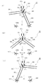
以下、上記センター役物41の動作について、前掲の図5とあわせて図14および図15を参照しながら説明する。図14および図15は、センター役物41の一連の動作における主要な段階を順次示す模式図であり、各動作段階におけるセンター役物41の模式正面図およびその模式縦断面図となっている。同図に示すセンター役物41は前記図8ないし図13に示す実施形態のものと同一のものであるが、明確化のため、各動作段階に関連する部分のみを簡略化して示してある。
Hereinafter, the operation of the center accessory 41 will be described with reference to FIGS. 14 and 15 together with FIG. FIG. 14 and FIG. 15 are schematic views sequentially showing main stages in a series of operations of the center accessory 41, and are a schematic front view and a schematic longitudinal sectional view of the center accessory 41 at each operation stage. The center accessory 41 shown in the figure is the same as that of the embodiment shown in FIGS. 8 to 13, but for the sake of clarity, only the parts related to each operation stage are shown in a simplified manner.
(1)図5に示す遊技領域において、センター役物41の上方に飛来する遊技球のうち、大多数は転動面411S上を左右方向に転動してその一方端から転落し、センター役物41の右下方または左下方へと流下していくが、少数の遊技球は、天入賞口42に入賞して所定の遊技球の払い出しが行われることとなるか、あるいは転動面411S上を転動する途上でうまく中上入賞口43に入球することとなる。
(1) In the game area shown in FIG. 5, the majority of the game balls flying above the center actor 41 roll on the rolling surface 411 </ b> S in the left-right direction and fall from one end thereof, The thing 41 flows down to the lower right or the lower left of the object 41, but a small number of game balls will win the top prize opening 42 and a predetermined game ball will be paid out or on the rolling surface 411S. In the middle of rolling, the player successfully enters the Nakagami winning opening 43.
(2)中上入賞口43に入球した遊技球は、図14(a)に示すように、球誘導路413P内を通り、その途上で入球センサ426により入球を検知されながら下方へ落下し、該球誘導路413Pの下端に連通するドラム414の内槽414Nの入球口414H(受球位置)に入球する。上記入球センサ426で中上入賞口43への入球が検出されると、前記LED基板415からの光の照射、前記可動装飾部材417R、417L、418R、418Lの稼働、前記音出力口24からの音の出力またはこれらの組み合わせから構成される所定の興趣演出が開始される。上記入球口414Hから内槽414N内に入った遊技球は、前述の通り係合片423の前側部分を押し下げ該係合片423を解除体勢としながら、回転体432の球収容部432R内に収容される。
(2) As shown in FIG. 14A, the game ball that has entered the middle upper winning opening 43 passes through the ball guiding path 413P and moves downward while being detected by the entrance sensor 426 on the way. The ball falls and enters a ball entrance 414H (ball receiving position) of the inner tank 414N of the drum 414 communicating with the lower end of the ball guide path 413P. When the entrance sensor 43 detects the entrance to the middle top winning opening 43, the light irradiation from the LED board 415, the operation of the movable decorative members 417R, 417L, 418R, 418L, and the sound output opening 24 are performed. A predetermined interest effect composed of the output of the sound from or a combination thereof is started. The game balls that have entered the inner tank 414N from the entrance 414H are pushed into the ball housing portion 432R of the rotating body 432 while pushing down the front side portion of the engaging piece 423 and releasing the engaging piece 423 as described above. Be contained.
(3)回転体432の球収容部432R内に遊技球が収容されると、図14(a)中の矢印A2に示すように、遊技球M1の重みにより回転体432を右回り(時計回り)に回転させるように力が働く。この状態では、係合片423は解除体勢にあって回転体432の回転を規制していないが、一方の球収容部432Rが同図に示すように上端に位置するとき、前記規制ピン432Pが規制溝414Gの左端に位置するようになっており、これにより回転体432の左回り(反時計回り)方向の回転は規制されている。また、このように回転体432が最大限に左回り方向に回転した位置にあるときに、上記球収容部432Rは、同図に示すようにその底部がやや右寄りに偏って位置するように形成され、さらに、該球収容部432Rの右側の内壁は平面状であるが左側の内壁は正面視円弧状の湾曲面状に成形されており、これにより、遊技球M1が右寄りに案内されやすいようになっている。したがって、回転体432は、球収容部432R内に遊技球M1を受容すると、矢印A2に示すように右回り(時計回り)方向に回転する。
なおこの時点では、フリップ432Fは自重により垂下されて一方面が前方に露出するとともに他方面が裏側に隠蔽された体勢にあり、回転体432の表面のうちの一方の半分(下側の半分)がフリップ432Fに覆われて隠蔽されるとともに他方の半分(上側の半分)が前方に露出した体勢となっており、これらフリップ432Fの露出面と回転体432の表面の露出部分とが、あわせて一つの円形の可視領域を構成しており、この可視領域に、特定の内容を表す一つの図柄(以下、この図柄を便宜的に「夜間型図柄」と称す)が表示されるようになっている(図示省略)。
(3) When a game ball is accommodated in the ball accommodating portion 432R of the rotator 432, the rotator 432 is rotated clockwise (clockwise) by the weight of the game sphere M1, as indicated by an arrow A2 in FIG. ) Force to rotate. In this state, the engaging piece 423 is in a releasing posture and does not restrict the rotation of the rotating body 432. However, when the one ball housing portion 432R is positioned at the upper end as shown in FIG. It is located at the left end of the restriction groove 414G, and thereby, the rotation of the rotating body 432 in the counterclockwise (counterclockwise) direction is restricted. Further, when the rotating body 432 is at the maximum counterclockwise rotation position as described above, the ball accommodating portion 432R is formed so that its bottom portion is positioned slightly to the right as shown in FIG. In addition, the inner wall on the right side of the ball housing portion 432R is planar, but the inner wall on the left side is formed into a curved surface with an arc shape when viewed from the front, so that the game ball M1 can be easily guided to the right. It has become. Accordingly, when the rotating body 432 receives the game ball M1 in the ball housing portion 432R, the rotating body 432 rotates in the clockwise (clockwise) direction as indicated by the arrow A2.
At this time, the flip 432F is suspended by its own weight, with one surface exposed forward and the other surface concealed behind, and one half of the surface of the rotating body 432 (the lower half). Is covered and concealed by the flip 432F, and the other half (the upper half) is exposed forward, and the exposed surface of the flip 432F and the exposed portion of the surface of the rotating body 432 are combined. A single circular visible region is formed, and one symbol representing specific contents (hereinafter referred to as “night-time symbol” for convenience) is displayed in the visible region. (Not shown).
(4)回転体432が右回り(時計回り)方向に回転する途上で、図14(b)に示すようにフリップ432Fの固定端である直線状の辺縁(軸ピン432Gが挿通されて回転体432に軸支された辺縁;以下、軸支端縁と称す)432Xが鉛直となる位置を右回り(時計回り)方向に超過すると、図中の矢印A3に示すように該フリップ432Fが自重により右下方向に落下するように反転して裏返る。このとき、該フリップ432Fは前述の通りスペーサ432Sにより回転体432の面上から所定の小角度だけ浮き上がった体勢に保持されているので、上記のような落下動作がより容易かつ確実になされるようになっており、また、この落下動作は、回転体432が引き続き右回り(時計回り)方向に回転する運動をさらに付勢する作用も奏する。また、フリップ432Fが上記のように反転すると、該フリップ432Fおよび回転体432の表面における露出部分と隠蔽部分とも反転して、別の可視領域が現れ、前記夜間型図柄と異なる(対照的な)内容を表す特定の一つの図柄(以下、この図柄を便宜的に「昼間型図柄」と称す)が表示されるようになっている(図示省略)。
(4) On the way the rotating body 432 rotates in the clockwise (clockwise) direction, as shown in FIG. 14B, the straight edge (the shaft pin 432G is inserted and rotated) that is the fixed end of the flip 432F When the edge 432X that is pivotally supported by the body 432 (hereinafter referred to as the pivotal support edge) 432X exceeds the vertical position in the clockwise (clockwise) direction, the flip 432F is moved as shown by an arrow A3 in the drawing. Flip it over so that it falls in the lower right direction due to its own weight. At this time, the flip 432F is held in a posture that is lifted by a predetermined small angle from the surface of the rotating body 432 by the spacer 432S as described above, so that the dropping operation as described above can be performed more easily and reliably. In addition, this dropping operation also exerts an action of further urging the movement of the rotating body 432 continuously rotating in the clockwise (clockwise) direction. Further, when the flip 432F is reversed as described above, the exposed portion and the concealed portion on the surface of the flip 432F and the rotating body 432 are also reversed, and another visible region appears, which is different from the night-type design (contrast). One specific symbol representing the contents (hereinafter, this symbol is referred to as “daytime symbol” for convenience) is displayed (not shown).
(5)回転体432がさらに右回り(時計回り)方向に回転して、図15(c)に示すように遊技球M1を収容した球収容部432Rが内槽414Nの排球口414Lに連通する位置(排球位置)まで到達すると、遊技球M1が球収容部432Rから下方に落下して、排球口414Lから排出される。
このとき、排球口414Lの直下には、該排球口414Lの開口面積および形状に対応する寸法および概略横長の箱体状の外形を有する、前記後側部材413の球排出部413Eが位置し、該排球口414Lに連通している。該球排出部413Eは、中央に方形状の隔壁413Tが形成されて内部が左右に2つの室すなわち左室C1および右室C2に仕切られた構成となっており、該左室C1および右室C2の各室中央には、後方にむけて下傾する上端縁を有する台形状の案内リブG1、G2がそれぞれ立設されている。遊技球M1は、排球口414Lに到達した後、図中の矢印A4に示すように右側の案内リブG2の上端縁に沿って後下方に誘導されつつ、該排球口414Lから排出されていく。この間、同図に示すように遊技球M1は、該案内リブG2上を移動することにより、回転体432と排球口414Lとを跨ぐ体勢に保持されつつ排出されていく。換言すれば、案内リブG2の上端縁は、遊技球M1を回転体432と排球口414Lとに跨がるような高さ位置の範囲内に保持しつつ後下方に誘導し得るような高さおよび勾配を有するように形成されている。
本実施形態では、上記案内リブG2は、隔壁413Tの右側面から右方に距離d1=約6.5mmだけ移動した位置、即ち上方の球収容部432Rから出てきた遊技球M1をそのほぼ中央で下方から支承し得る位置に形成され、前後方向の幅w1=約15mm、後側端縁の高さh1=約11mm、前側端縁の高さh2=約5mmとなっており、図15(c)に示すように、上方からきた遊技球M1を受けた時点で、該遊技球M1をその中心Oの高さ位置が回転体432の下端の高さ位置にほぼ等しくなるような高さ位置で下方から支承し得るような高さ位置に形成されている。
(5) The rotating body 432 further rotates clockwise (clockwise), and the ball housing portion 432R that houses the game ball M1 communicates with the ball outlet 414L of the inner tank 414N as shown in FIG. 15 (c). When reaching the position (ball throwing position), the game ball M1 falls downward from the ball housing portion 432R and is discharged from the ball throwing opening 414L.
At this time, a ball discharge portion 413E of the rear member 413 having a size corresponding to the opening area and shape of the discharge port 414L and a substantially horizontally long box-shaped outer shape is located immediately below the discharge port 414L. It communicates with the ball outlet 414L. The ball discharge portion 413E has a configuration in which a rectangular partition wall 413T is formed in the center and the inside is divided into two chambers, that is, a left chamber C1 and a right chamber C2, and the left chamber C1 and the right chamber In the center of each chamber of C2, trapezoidal guide ribs G1 and G2 each having an upper end edge inclined downward toward the rear are erected. After reaching the ball outlet 414L, the game ball M1 is discharged from the ball outlet 414L while being guided rearward and downward along the upper edge of the right guide rib G2 as indicated by an arrow A4 in the drawing. During this time, as shown in the figure, the game ball M1 moves on the guide rib G2 and is discharged while being held in a posture straddling the rotating body 432 and the ball outlet 414L. In other words, the upper edge of the guide rib G2 has a height that can guide the game ball M1 rearward and downward while holding the game ball M1 within a range of a height position that spans the rotating body 432 and the ball outlet 414L. And have a gradient.
In the present embodiment, the guide rib G2 moves the game ball M1 that has been moved from the right side surface of the partition wall 413T to the right by a distance d1 = about 6.5 mm, that is, from the upper ball housing portion 432R. 15, the width w1 in the front-rear direction is about 15 mm, the height h1 of the rear side edge is about 11 mm, and the height h2 of the front side edge is about 5 mm. As shown in c), when the game ball M1 coming from above is received, the height position of the game ball M1 is such that the height position of the center O is substantially equal to the height position of the lower end of the rotating body 432. It is formed in the height position which can be supported from below.
上記のように球収容部432Rが排球位置、具体的には球排出部413Eの右室C2の上方に位置するとき、前記規制ピン432Pが規制溝414Gの右端に位置するようになっており、これにより、球収容部432Rが遊技球M1を収容したまま排球位置を超過して回転しないよう、回転体432の右回り(時計回り)方向の回転は規制される。したがって、このときの位置は回転体432が最大限に右回り方向に回転した位置すなわち右回り方向の限界位置であるが、これまで回転体432は上述の通り遊技球M1の重みにより回転運動をしてきているので、この限界位置で反発力が生じ、これまでとは逆の方向すなわち左回り(反時計回り)方向に戻るように弾む(バウンドする)挙動をとろうとする。もしこのようなバウンド動作がなされると、上記球収容部432Rが上端部の入球口414Hすなわち受球位置にまで戻ってしまい、後述するようなもう一方の球収容部432Lによる遊技球の案内(受け渡し)動作へと正しく移行されなくなる惧れもあるが、ここで、上記のように遊技球M1が回転体432と排球口414Lとを跨ぐ体勢に保持されつつ排出されることにより、回転体432が遊技球M1によりロックされて排球位置に保持され、バウンド動作が抑止される。即ち、遊技球M1が回転体432と排球口414Lとを跨ぐ体勢にあると、回転体432が左回り(反時計回り)方向にバウンドしようとしても、遊技球M1が排球口414Lに拘束された(引っかかった)体勢となっていて左回り(反時計回り)方向には動き得ず、このため回転体432の左回り(反時計回り)方向への動きも遊技球M1に阻止される。換言すれば、遊技球M1が、回転体432と排球口414Lとを跨ぐように位置して該回転体432を排球位置にロックする「かんぬき」のように機能するのである。
As described above, when the ball housing portion 432R is located at the ball discharge position, specifically, above the right chamber C2 of the ball discharge portion 413E, the restriction pin 432P is located at the right end of the restriction groove 414G. As a result, the rotation of the rotating body 432 in the clockwise (clockwise) direction is restricted so that the ball housing portion 432R does not rotate beyond the ball discharge position while housing the game ball M1. Therefore, the position at this time is a position where the rotator 432 is rotated clockwise as much as possible, that is, a limit position in the clockwise direction, but until now the rotator 432 is rotated by the weight of the game ball M1 as described above. Therefore, a repulsive force is generated at this limit position and tries to take a behavior of bouncing (bounding) in the opposite direction, that is, counterclockwise (counterclockwise). If such a bounce operation is performed, the ball housing portion 432R returns to the entrance 414H at the upper end, that is, the ball receiving position, and guides the game ball by the other ball housing portion 432L as will be described later. There is a possibility that the transfer to the (delivery) operation may not be performed correctly. Here, the game ball M1 is discharged while being held in a posture straddling the rotation body 432 and the ball outlet 414L as described above. 432 is locked by the game ball M1 and held at the ball-discharging position, and the bounce operation is suppressed. That is, when the game ball M1 is in a posture straddling the rotating body 432 and the ball outlet 414L, the game ball M1 is restrained by the ball outlet 414L even if the rotor 432 tries to bounce counterclockwise (counterclockwise). It is in a posture that is (hooked) and cannot move in the counterclockwise (counterclockwise) direction, and therefore the movement of the rotating body 432 in the counterclockwise (counterclockwise) direction is also prevented by the game ball M1. In other words, the game ball M1 functions as a “kanuki” that is positioned so as to straddle the rotating body 432 and the ball outlet 414L and locks the rotating body 432 in the ball discharging position.
(6)案内リブG2の上端縁に沿って後下方に誘導された遊技球M1は、図15(d)に示すように、後方で前記裏側カバー429の突出部429Eの内面に行当って下方へ案内され、排球センサ427により検知されながら、センター役物41から下方へ排出されていく。裏側カバー429の突出部429Eは、左右に長く延びる直方体状の内部空間が中央の隔壁により左右に2つの区画すなわち左区画429Lおよび右区画429Rに分割され、これら左区画429Lおよび右区画429Rはそれぞれ前記排出部413Eの左室C1および右室C2に連通して、左側通路および右側通路の2通路から構成される排球通路の後側部を構成している。該左区画429Lおよび右区画429Rの各区画の内部における後上の隅部には、後下方へ下傾する下端縁を有するガイドリブ429Gがそれぞれ突設されており、遊技球を下方へ案内するようになっている。また、排球センサ427は、上記突出部429Eの左区画429Lおよび右区画429Rの直下にそれぞれ検出部427L、427Rを備え、遊技球が左側通路および右側通路のいずれから排出されたかが検知され、この結果に応じた興趣演出がなされる構成となっている。
(6) As shown in FIG. 15 (d), the game ball M1 guided rearward and downward along the upper edge of the guide rib G2 hits the inner surface of the protruding portion 429E of the back side cover 429 and lowers as shown in FIG. , And is discharged downward from the center accessory 41 while being detected by the ball sensor 427. The projecting portion 429E of the back cover 429 has a rectangular parallelepiped internal space extending in the left and right directions, and is divided into two sections on the left and right sides by a central partition, that is, a left section 429L and a right section 429R. It communicates with the left chamber C1 and the right chamber C2 of the discharge portion 413E, and constitutes the rear side portion of the drainage passage constituted by two passages, a left passage and a right passage. Guide ribs 429G having lower end edges that tilt downward to the rear and below are projected from the upper rear corners of the left and right sections 429L and 429R so as to guide the game balls downward. It has become. The ball discharge sensor 427 includes detection units 427L and 427R directly below the left and right sections 429L and 429R of the protrusion 429E, respectively, to detect whether the game ball is discharged from the left or right path. It is configured to produce an interesting performance according to the situation.
遊技球M1が排球口414Lから排出され、回転体432から完全に離脱すると、該遊技球M1による回転体432の回転の規制すなわち「かんぬき」様の機能も解除されるが、これよりも以前に、即ち該遊技球M1が回転体432から完全に離脱しておらず回転体432が排球位置にロックされているうちに、前記係合片423が係合体勢に復帰して、その前側部分が前方の回転体432の上端部まで突き出し、今度はかわって上端に位置するもう一方の球収容部432Lの内壁に係合し、これにより回転体432が引き続き排球位置にロックされる。係合片423は、前述の通り遊技球M1の通過によって解除体勢となった後、回転体432が回転している間はその回転運動を規制しないが、回転体432が最大限にまで回転して遊技球M1を収容した球収容部432Rが排球位置に達すると、これにともなってもう一方の球収容部432Lが上端部に達し、該球収容部432Lの内部空間により係合片423の前方に動作スペースが再び確保されて係合体勢に復帰する動作が可能となる。ただし、この係合片423の復帰動作は、前記回転体432が右回り方向の限界位置に達した時点よりも若干遅れて開始されるため、回転体432が右回り方向の限界位置に達すると、当初は前述の通り遊技球M1が回転体432の回転を規制するように機能し、この遊技球M1によるロック機能が解除されるよりもやや早く、このロック機能を引き継ぐような形で、該係合片423が回転体432を引き続き排球位置にロックするように機能する。
When the game ball M1 is discharged from the ball outlet 414L and completely disengages from the rotating body 432, the restriction of the rotation of the rotating body 432 by the game ball M1, that is, the function of “Kanuki” is also released. That is, while the game ball M1 is not completely detached from the rotating body 432 and the rotating body 432 is locked at the ball discharging position, the engaging piece 423 returns to the engaging posture, and the front portion thereof is It protrudes to the upper end portion of the front rotating body 432, and this time, instead, engages with the inner wall of the other ball housing portion 432L positioned at the upper end, whereby the rotating body 432 is continuously locked at the ball discharging position. The engaging piece 423 does not restrict the rotational movement while the rotating body 432 is rotating after the releasing body 432 is released by passing the game ball M1 as described above, but the rotating body 432 rotates to the maximum. When the ball storage portion 432R that stores the game ball M1 reaches the ball discharge position, the other ball storage portion 432L reaches the upper end, and the front space of the engagement piece 423 is reached by the internal space of the ball storage portion 432L. Thus, the operation space is secured again, and the operation of returning to the engagement posture is enabled. However, the returning operation of the engagement piece 423 is started slightly later than the time when the rotating body 432 reaches the limit position in the clockwise direction, and therefore when the rotating body 432 reaches the limit position in the clockwise direction. Initially, as described above, the game ball M1 functions to regulate the rotation of the rotating body 432, and the lock function by the game ball M1 is released slightly earlier than the lock function. The engagement piece 423 functions to lock the rotating body 432 continuously at the ball discharging position.
(7)上述の通り、遊技球M1が回転体432の球収容部432R内に収容され、ドラム414の内槽414Nにおける内周面の右側半分に沿って上端から下端部まで案内され、右側通路から排出されると、連絡通路により、遊技盤4の裏側においてさらに下方に案内される。該連絡通路は、上記センター役物41の右側通路に連通して下方に延びる右側連絡通路と、センター役物41の左側通路に連通して下方に延びる左側連絡通路とを左右に並置するようにして構成されている(図示省略)。
(7) As described above, the game ball M1 is accommodated in the ball accommodating portion 432R of the rotating body 432, and is guided from the upper end to the lower end along the right half of the inner peripheral surface of the inner tank 414N of the drum 414. When it is discharged from the game board 4, it is guided further downward on the back side of the game board 4 by the communication passage. The communication passage is arranged such that a right communication passage that extends downward and communicates with the right passage of the center accessory 41 and a left communication passage that communicates with the left passage of the center accessory 41 and extends downward are arranged side by side. (Not shown).
上記連絡通路の下方には、図7に示すように、右リンク機構L1が配置され、該右リンク機構L1の下方には下リンク機構L2が配置され、さらに上記右リンク機構L1の左方(図7上では右方)には左リンク機構L3が配置されている。上記右リンク機構L1においては、図16(a)に示すように、右側連絡通路に案内されて上方から入球してきた遊技球M1は、第1アームR1の先端に載って自重により該第1アームR1を押し下げ、該第1アームR1はリンク機構により第2アームR2を介して第3アームR3の先端を押し下げ、該第3アームR3の先端は前記中央入賞装置46の可動翼(チューリップ)46Tを開放するように駆動する。またこのとき、図17(a)および(b)に示すように、上記第3アームR3には第4アームR4を介して第5アームR5が連結されており、該第5アームR5が、上記第3アームR3と連動して、前記下段側右中入賞装置49Bの可動翼(チューリップ)49Tを開放するように駆動する。
As shown in FIG. 7, a right link mechanism L1 is disposed below the communication path, a lower link mechanism L2 is disposed below the right link mechanism L1, and further to the left of the right link mechanism L1 ( A left link mechanism L3 is arranged on the right side in FIG. In the right link mechanism L1, as shown in FIG. 16 (a), the game ball M1 guided by the right communication passage and entered from the upper side is placed on the tip of the first arm R1 by its own weight. The arm R1 is pushed down, the first arm R1 pushes down the tip of the third arm R3 via the second arm R2 by a link mechanism, and the tip of the third arm R3 is the movable wing (tulip) 46T of the central prize winning device 46 Drive to release. At this time, as shown in FIGS. 17A and 17B, the third arm R3 is connected to the fifth arm R5 via the fourth arm R4, and the fifth arm R5 is connected to the third arm R3. In conjunction with the third arm R3, the movable wing (tulip) 49T of the lower right side middle winning device 49B is driven to open.
上記遊技球M1は、第1アームR1を押し下げた後、該第1アームR1の先端から落下して、下方に設置された下リンク機構L2に案内される。上記下リンク機構L2においては、図18(a)に示すように、遊技球M1は、前記右リンク機構L1における第1ないし第3アームR1〜R3の場合と同様に、第6アームR6の先端に載って自重により該第6アームR6を押し下げ、該第6アームR6はリンク機構により第7アームR7を介して第8アームR8の先端を押し下げ、該第8アームR8の先端は前記下段側左下入賞装置55Bの可動翼(チューリップ)55Tを開放するように駆動する。またこのとき、図19(a)および(b)に示すように、上記第8アームR8には第9アームR9を介して第10アームR10が連結されており、該第10アームR10が、上記第8アームR8と連動して、前記下段側中下入賞装置47Bの可動翼(チューリップ)47Tを開放するように駆動する。さらにまたこのとき、図20(a)および(b)に示すように、上記第9アームR9には第10アームR10とともに第11アームR11が連結されており(即ち、第9アームR9は左右に延びるように架設され、左端には第8アームR8が、中央には第10アームR10が、右端には第11アームR11がそれぞれ連結されている)、該第11アームR11が、上記第8アームR8と連動して、前記下段側右下入賞装置48Bの可動翼(チューリップ)48Tを開放するように駆動する。上記のように駆動した後の右リンク機構L1および下リンク機構L2は、錘(図示せず)により、それぞれ駆動する前の体勢に復帰するようになっており、また、開放した状態の5対の可動翼(チューリップ)46T、49T、55T、47T、48Tは、この後遊技領域においてそれぞれ遊技球が入球することにより閉じるようになっている。
After the first arm R1 is pushed down, the game ball M1 falls from the tip of the first arm R1, and is guided to the lower link mechanism L2 installed below. In the lower link mechanism L2, as shown in FIG. 18 (a), the game ball M1 is positioned at the tip of the sixth arm R6 as in the case of the first to third arms R1 to R3 in the right link mechanism L1. The sixth arm R6 is pushed down by its own weight, the sixth arm R6 pushes down the tip of the eighth arm R8 via the seventh arm R7 by the link mechanism, and the tip of the eighth arm R8 is the lower left side of the lower stage. The movable wing (tulip) 55T of the winning device 55B is driven to open. At this time, as shown in FIGS. 19A and 19B, a tenth arm R10 is connected to the eighth arm R8 via a ninth arm R9, and the tenth arm R10 is connected to the eighth arm R8. In conjunction with the eighth arm R8, the movable wing (tulip) 47T of the lower middle winning device 47B is driven to open. Furthermore, at this time, as shown in FIGS. 20A and 20B, the ninth arm R9 is connected to the eleventh arm R11 together with the tenth arm R10 (that is, the ninth arm R9 is moved to the left and right). The eighth arm R8 is connected to the left end, the tenth arm R10 is connected to the center, and the eleventh arm R11 is connected to the right end. The eleventh arm R11 is connected to the eighth arm. In conjunction with R8, the lower wing lower right winning device 48B is driven to open the movable wing (tulip) 48T. The right link mechanism L1 and the lower link mechanism L2 after being driven as described above are returned to their postures before being driven by weights (not shown), and are opened in five pairs. Thereafter, the movable wings (tulips) 46T, 49T, 55T, 47T, and 48T are closed by entering the game balls in the game area.
上記のように、遊技球M1が右側連絡通路から下方に案内されて右リンク機構L1を通過すると、該右リンク機構L1を駆動して前記中央入賞装置46および下段側右中入賞装置49Bのそれぞれの可動翼(チューリップ)46T、49Tを同時に開放し、この後、下リンク機構L2を通過すると、該下リンク機構L2を駆動して前記下段側左下入賞装置55B、下段側中下入賞装置47Bおよび下段側右下入賞装置48Bのそれぞれの可動翼(チューリップ)55T、47T、48Tを同時に開放する。このとき、パチンコ機10は、上記5つの入賞装置が入賞可能となり、遊技領域内において遊技球が比較的に入賞しやすい状態となる(以下、この状態を「昼間型遊技状態」と称す)。この昼間型遊技状態となる以前は、遊技者は、主として、該昼間型遊技状態への移行を期して中上入賞口43に狙いをおき、これと同時に、遊技球の払い出しを期して天入賞口42に狙いをおいて遊技を行う、即ちセンター役物41の上端部に重点的に狙いをおくと考えられるが、昼間型遊技状態へ移行した後は、可動翼(チューリップ)46T、49T、55T、47T、48Tが開放されて入賞可能となった上記中央入賞装置46、下段側中下入賞装置47B、下段側右下入賞装置48B、下段側右中入賞装置49Bならびに下段側左下入賞装置55Bの5つの入賞装置を重点的に狙うようになると考えられる。
As described above, when the game ball M1 is guided downward from the right communication passage and passes through the right link mechanism L1, the right link mechanism L1 is driven to each of the central winning device 46 and the lower middle right winning device 49B. The movable wings (tulips) 46T and 49T are simultaneously opened, and thereafter, when passing through the lower link mechanism L2, the lower link mechanism L2 is driven to lower the lower left side winning device 55B, the lower middle winning device 47B, The movable wings (tulips) 55T, 47T, and 48T of the lower stage lower right winning device 48B are simultaneously opened. At this time, the pachinko machine 10 can win the above five winning devices, and the game ball is in a state where it is relatively easy to win in the game area (hereinafter, this state is referred to as “daytime game state”). Prior to this daytime gaming state, the player mainly aimed at the middle upper prize opening 43 in preparation for the transition to the daytime gaming state, and at the same time, paid out the game balls to win the Tenchi Prize. It is considered that the game is aimed at the mouth 42, that is, focussed on the upper end portion of the center actor 41, but after the transition to the daytime game state, the movable wings (tulips) 46T, 49T, The above-mentioned center winning device 46, lower side middle / lower winning device 47B, lower side right lower winning device 48B, lower side right middle winning device 49B and lower side left lower winning device 55B, which are open when 55T, 47T, 48T are opened. It is thought that the five winning devices will be focused on.
上記昼間型遊技状態で入賞可能とされる5つの入賞装置には、いずれも前記したように前面に「太陽」を模した装飾が統一して施されており、一方、この時点では前記センター役物41における回転体432の前面には昼間型図柄が表示されているが、該昼間型図柄は「太陽」と関連する内容の図柄となっており、したがって、該昼間型図柄は、演出効果とともに、昼間型遊技状態にあることを遊技者に報知する機能も奏するものとなっている。
As described above, the five winning devices that can be awarded in the daytime gaming state are uniformly decorated with “sun” on the front surface. Although the daytime pattern is displayed on the front surface of the rotating body 432 of the object 41, the daytime pattern is a pattern related to the “sun”. Therefore, the daytime pattern has a production effect. In addition, it also has a function of notifying the player that it is in the daytime gaming state.
(8)上記昼間型遊技状態にあるときに、別の遊技球が中上入賞口43に入球すると、図示省略するが、該遊技球は、前記と全く同様に、球誘導路413P内を通って下方へ落下し、ドラム414の内槽414Nの入球口414H(受球位置)に入球して、係合片423を解除体勢としながら、回転体432のもう一方の球収容部432L内に収容される。このとき、回転体432の上端部に位置する該球収容部432Lは、下端部の排球位置に位置する前記球収容部432Rと左右対称をなすように形成されている。即ち、両球収容部432R、432Lは前記フリップ432Fの軸支端縁432Xに関して線対称となるように形成されている。したがって、昼間型遊技状態で上記球収容部432L内に収容された遊技球は、前述のように遊技球M1がドラム414内で右側を通るように案内される場合とは左右対称の軌道を描くようにして、即ち、ドラム414の内槽414Nにおける内周面の左側半分に沿って上端から下端部まで案内される。この途上で、前記フリップ432Fが再び反転して、前記夜間型図柄が表示される。
(8) While in the daytime game state, if another game ball enters the middle upper prize opening 43, the illustration of the game ball is made in the ball guiding path 413P, exactly as described above. It passes through and falls downward, enters the entrance 414H (receiving position) of the inner tank 414N of the drum 414, and makes the engaging piece 423 in a releasing posture, while the other ball accommodating portion 432L of the rotating body 432 is used. Housed inside. At this time, the ball housing portion 432L located at the upper end of the rotating body 432 is formed to be bilaterally symmetric with the ball housing portion 432R located at the lower ball discharge position. That is, both the ball accommodating portions 432R and 432L are formed to be line-symmetric with respect to the shaft support end edge 432X of the flip 432F. Therefore, the game ball accommodated in the ball accommodating portion 432L in the daytime game state has a symmetrical trajectory as described above when the game ball M1 is guided to pass through the right side in the drum 414. Thus, that is, it is guided from the upper end to the lower end along the left half of the inner peripheral surface of the inner tank 414N of the drum 414. On the way, the flip 432F is reversed again, and the night-time symbol is displayed.
下端部まで案内された遊技球は、球排出部413Eの左室C1の上方に到達し、前記と全く同様に、左側の案内リブG1の上端縁に沿って後下方に誘導されつつ、排球口414Lから排出されていく。上記案内リブG1を含め、左室C1は前記右室C2と左右対称に構成されており、遊技球は、前記右側の場合と全く同様に、該案内リブG1上を移動することにより、回転体432と排球口414Lとを跨ぐ体勢に保持されつつ排出されていく。このとき、前記規制ピン432Pは規制溝414Gの左端に位置して回転体432の左回り(反時計回り)方向の回転は規制され、回転体432は左回り方向の限界位置にあるが、前記右側の場合と全く同様に、遊技球が回転体432と排球口414Lとを跨ぐ体勢に保持されつつ排出されることにより、回転体432が遊技球によりロックされて排球位置に保持され、バウンド動作が抑止される。
The game ball guided to the lower end reaches the upper portion of the left chamber C1 of the ball discharge portion 413E and is guided backward and downward along the upper end edge of the left guide rib G1 in the same manner as described above. It is discharged from 414L. The left chamber C1, including the guide rib G1, is configured to be symmetrical with the right chamber C2, and the game ball moves on the guide rib G1 in the same manner as in the right side, thereby rotating the rotating body. It is discharged while being held in a posture straddling 432 and the ball outlet 414L. At this time, the restriction pin 432P is located at the left end of the restriction groove 414G and the rotation of the rotating body 432 in the counterclockwise direction is restricted, and the rotating body 432 is at the limit position in the counterclockwise direction. Just as in the case of the right side, the game ball is discharged while being held in a posture straddling the rotary body 432 and the ball outlet 414L, so that the rotary body 432 is locked by the game ball and held at the ball discharge position, and the bounce operation Is suppressed.
左側の案内リブG1の上端縁に沿って後下方に誘導された遊技球は、後方で前記裏側カバー429の突出部429Eにおける左区画429Lの内面に行当って下方へ案内され、排球センサ427の左側の検出部427Lにより検知されながら、センター役物41から下方へ排出されていく。また一方で、係合片423が前記と全く同様にして係合体勢に復帰し、この時点で上端に復帰している前記球収容部432Rの内壁に係合し、これにより回転体432が引き続き排球位置にロックされる。即ち、回転体432および係合片423は、前述のように遊技球M1が中上入賞口43に入球して昼間型遊技状態に移行するより以前の状態に復帰してこの状態に保持される。
The game ball guided rearward and downward along the upper end edge of the left guide rib G1 hits the inner surface of the left section 429L in the protruding portion 429E of the back cover 429 and is guided downward. While being detected by the left detection unit 427L, the center accessory 41 is discharged downward. On the other hand, the engagement piece 423 returns to the engagement posture in exactly the same manner as described above, and engages with the inner wall of the ball housing portion 432R that has returned to the upper end at this point, whereby the rotating body 432 continues to be engaged. Locked to the ball-discharging position. That is, the rotating body 432 and the engaging piece 423 are returned to the previous state and held in this state before the game ball M1 enters the middle and upper prize opening 43 and shifts to the daytime gaming state as described above. The
(9)遊技球が上述のようにドラム414内で左側を通るように案内され、左側通路から排出されると、前記左側連絡通路を通り、下方に配置された前記左リンク機構L3に案内される。上記左リンク機構L3においては、図21(a)に示すように、左側連絡通路に案内されて上方から入球してきた遊技球M11は、第12アームR12の先端に載って自重により該第12アームR12を押し下げ、該第12アームR12はリンク機構により第13アームR13を介して第14アームR14の先端を押し下げ、該第14アームR14の先端は前記下段側左中入賞装置56Bの可動翼(チューリップ)56Tを開放するように駆動する。
(9) As described above, the game ball is guided to pass through the left side in the drum 414, and when it is discharged from the left passage, it is guided to the left link mechanism L3 disposed below through the left communication passage. The In the left link mechanism L3, as shown in FIG. 21 (a), the game ball M11 that has been guided by the left communication passage and entered from above is placed on the tip of the twelfth arm R12 and caused by its own weight. The arm R12 is pushed down, the twelfth arm R12 pushes down the tip of the fourteenth arm R14 via the thirteenth arm R13 by a link mechanism, and the tip of the fourteenth arm R14 is the movable wing ( Tulip) Drive to open 56T.
このとき、前記5対の可動翼(チューリップ)46T、49T、55T、47T、48Tが開いていてこれら可動翼を備える5つの入賞装置がいずれも入賞可能な状態にある場合、これに加えて上記下段側左中入賞装置56Bの可動翼(チューリップ)56Tが開放されて計6つの入賞装置がいずれも入賞可能な状態となり、したがって遊技領域内において遊技球が最も入賞しやすい状態となるとも考えられるが、このような場合は稀であり、多くの場合、上記下段側左中入賞装置56Bが入賞可能となるより以前に、前記5対の可動翼(チューリップ)46T、49T、55T、47T、48Tを備える5つの入賞装置のうちの少なくとも1つ(1つないし5つ)はすでに遊技球の入賞により可動翼が閉じて入賞不能な状態に復帰している蓋然性が高いと考えられる。よって、上記下段側左中入賞装置56Bが入賞可能となると、上記6対の可動翼(チューリップ)を備える6つの入賞装置のうち、最大で計6つ、多くの場合は5つ以下の入賞装置が入賞可能となり、パチンコ機10は、遊技領域内において遊技球が前記昼間型遊技状態よりも入賞しやすい状態、前記昼間型遊技状態と同程度に入賞しやすい状態ならびに前記昼間型遊技状態に次いで入賞しやすい状態のいずれの状態ともなり得るが、いずれの場合であれ、上記6つの入賞装置のうち入賞可能となっているものの組み合わせは異なる状態となる(以下、この状態を「夜間型遊技状態」と称す)。
At this time, if the five pairs of movable wings (tulips) 46T, 49T, 55T, 47T, and 48T are open and any of the five winning devices including these movable wings is in a state where a prize can be awarded, in addition to the above, The movable wings (tulips) 56T of the lower left side middle winning device 56B are opened, and all the six winning devices are ready for winning. Therefore, it is considered that the game ball is most likely to win in the gaming area. However, such a case is rare, and in many cases, the five pairs of movable wings (tulips) 46T, 49T, 55T, 47T, 48T before the lower left side middle winning device 56B can win. At least one of the five winning devices (1 to 5) including the above has already returned to a state where the movable wing is closed and the winning is impossible due to the winning of the game ball. Natural sex is considered to be high. Therefore, when the lower left side middle winning device 56B can win, a maximum of six winning devices out of the six winning devices including the six pairs of movable wings (tulips), and in many cases not more than five winning devices. Can be won, and the pachinko machine 10 is next to a state in which a game ball is more likely to win in the game area than the daytime gaming state, a state in which it is as easy to win as the daytime gaming state, and the daytime gaming state. In any case, the combination of the six winning devices that can be won will be different (this state will be referred to as “night game state” hereinafter). ").
上記夜間型遊技状態に移行した後、遊技者は、上記6つの入賞装置のうち多数が入賞可能となっている場合には、引き続きこれら入賞可能な入賞装置を狙うものと考えられるが、入賞可能な入賞装置が残り少なくなっていくにつれ、再び遊技状態を昼間型遊技状態へ移行させて上記6つの入賞装置のうち(下段側左中入賞装置56B以外の)5つの入賞装置をいずれも入賞可能とすることを期して、中上入賞口43を中心としてセンター役物41の上端部に狙いの重点を戻していくと考えられる。
After the transition to the night-type gaming state, if a large number of the above six winning devices can be won, the player may continue to aim for those winning devices that can be won. As the remaining number of winning devices decreases, the game state is again shifted to the daytime gaming state, and all of the five winning devices (other than the lower left middle winning device 56B) can be won. In view of this, it is considered that the focus of the aim is returned to the upper end portion of the center accessory 41 around the middle prize winning port 43.
上記夜間型遊技状態で開放される下段側左中入賞装置56Bには、前記したように前面に「星」を模した装飾が施されており、一方、この時点では前記センター役物41における回転体432の前面には夜間型図柄が表示されているが、該夜間型図柄は「星」と関連する内容の図柄となっており、したがって、該夜間型図柄は、演出効果とともに、夜間型遊技状態にあることを遊技者に報知する機能も奏するものとなっている。
As described above, the lower left middle winning device 56B that is opened in the night-type gaming state is decorated with “stars” on the front as described above. Although the night-type symbol is displayed on the front of the body 432, the night-type symbol is a symbol related to the “star”. It also has a function of notifying the player that it is in a state.
以上の通り、センター役物41は、中上入賞口43に入球した遊技球を、右下方向と左下方向とに交互に案内するように機能し、この案内方向に応じて、「太陽」の装飾を有する5つの入賞装置に連結されたリンク機構すなわち右リンク機構L1および下リンク機構L2と、「星」の装飾を有する下段側左中入賞装置56Bに連結されたリンク機構すなわち左リンク機構L3とが交互に駆動されることで、遊技状態が昼間型遊技状態と夜間型遊技状態とに交互に入れ替わるように移行するようになっている。ここで、もし、例えば昼間型遊技状態への移行がなされてから、次の中上入賞口43への入球ではなく回転体432のバウンド動作や不正に加えられた振動等によって回転体432が元の位置(左右回り方向の限界位置)に戻ったりすると、次に中上入賞口43に遊技球が入球しても、遊技球が前回の入球の場合と同じく右下方向に繰り返して案内されるため、昼間型遊技状態から夜間型遊技状態への移行はなされず、昼間型遊技状態が更新されて再び5つの入賞装置がいずれも入賞可能となり、したがって遊技者にとってより有利な遊技状態が不適正に継続することとなる。ところが、前述の通り、上記センター役物41においては、遊技球が回転体432と排球口414Lとを跨ぐ体勢に保持されつつ排出されること、ならびに係合片423が球収容部432Lに係合することにより、回転体432が確実に排球位置にロックされるようになっているので、バウンド動作は抑止され、また不正に振動が加えられたりしても回転体432は回転せず、次に中上入賞口43に遊技球が入球するまでは元の位置に戻ることはない。したがって、昼間型遊技状態と夜間型遊技状態との間の移行が中上入賞口43への入球に応じて適正になされるようになっている。
As described above, the center accessory 41 functions to guide the game balls that have entered the middle upper winning opening 43 alternately in the lower right direction and the lower left direction, and according to this guidance direction, the “sun” Link mechanism, that is, the right link mechanism L1 and the lower link mechanism L2, which are connected to the five winning devices having decorations, and the link mechanism, that is, the left link mechanism, which is connected to the lower left side middle winning device 56B having the “star” decoration. By alternately driving L3, the game state is shifted so as to be alternately switched between the daytime game state and the nighttime game state. Here, for example, after the transition to the daytime gaming state is made, the rotating body 432 does not enter the next middle / upper winning hole 43 but by the bounding motion of the rotating body 432 or improperly applied vibrations. When returning to the original position (the limit position in the left-right direction), even if the game ball enters the middle upper winning hole 43 next, the game ball repeats in the lower right direction as in the previous entry. Because it is guided, the transition from the daytime gaming state to the nighttime gaming state is not made, and the daytime gaming state is updated so that all five winning devices can win again, so that the gaming state is more advantageous for the player. Will continue improperly. However, as described above, in the center accessory 41, the game ball is discharged while being held in a posture straddling the rotating body 432 and the ball outlet 414L, and the engagement piece 423 is engaged with the ball housing portion 432L. By doing so, the rotating body 432 is surely locked at the ball-rejecting position, so that the bounce operation is suppressed and the rotating body 432 does not rotate even if improper vibration is applied. The game ball does not return to the original position until the game ball enters the middle upper prize opening 43. Therefore, the transition between the daytime game state and the nighttime game state is appropriately made according to the ball entering the middle upper prize opening 43.
(作用)
上記パチンコ機10の構成によれば、所定の受球位置すなわちドラム414の内槽414Nの入球口414Hで遊技球を受容し、該受球位置から所定距離をおいた(約150〜160°程度の角度だけ離れた)排球位置まで該遊技球を移動させて、該排球位置に形成された排出口すなわち排球口414Lに該遊技球を排出するように動作する可動体すなわち回転体432を備えるセンター役物41が遊技領域に配置された構成において、上記遊技球が上記排球位置にきたときに、該遊技球を上記回転体432と上記排球口414Lとを跨ぐ体勢に保持しつつ排出するように誘導する球進路誘導手段として案内リブG1、G2が設けられている構成としたので、回転体432が排球位置まで移動してきてバウンドしようとした場合でも、遊技球が排出される際に案内リブG1、G2により遊技球が回転体432と排球口414Lとを跨ぐ体勢に保持されること、換言すれば、遊技球が回転体432と排球口414Lとを跨ぐ体勢に保持されるようにその進路が誘導されつつ排出されることで、該回転体432が遊技球によりロックされて排球位置に保持され、バウンド動作が抑止されるようになっている。即ち、遊技球が、排出される際にそのまま無条件に排出されるのではなく、回転体432と排球口414Lとを跨ぐように位置して該回転体432を排球位置にロックする「かんぬき」のように機能するようになっている。このように遊技球自体に回転体432の動きを抑止するように機能させながら該遊技球を排出する構成となっていることで、回転体432の動きを抑止するための機構を別に必要とすることなく、案内リブG1、G2を設けるだけの簡略な構成によって回転体432に所望の動作を容易かつ確実に行わせることが可能なセンター役物41となっている。
(Function)
According to the configuration of the pachinko machine 10, the game ball is received at a predetermined ball receiving position, that is, the entrance 414H of the inner tank 414N of the drum 414, and a predetermined distance from the ball receiving position (about 150 to 160 °). There is provided a movable body or rotating body 432 that operates to move the game ball to a ball discharge position (separated by a certain angle) and discharge the game ball to a discharge port formed at the ball discharge position, ie, a ball discharge port 414L. In the configuration in which the center accessory 41 is arranged in the game area, when the game ball comes to the ball discharge position, the game ball is discharged while being held in a posture straddling the rotating body 432 and the ball discharge port 414L. Since the guide ribs G1 and G2 are provided as the ball course guiding means for guiding to the ball, even if the rotating body 432 moves to the ball discharging position and tries to bounce, the game ball When discharged, the game balls are held in a posture straddling the rotating body 432 and the ball outlet 414L by the guide ribs G1 and G2, in other words, the game balls are straddling the rotor 432 and the ball outlet 414L. By being discharged while being guided so as to be held, the rotating body 432 is locked by the game ball and held at the ball-discharging position, and the bounce operation is suppressed. That is, when the game ball is discharged, it is not discharged unconditionally, but is positioned so as to straddle the rotating body 432 and the ball outlet 414L and lock the rotating body 432 at the ball discharging position. It is supposed to function like. In this way, the game ball itself is configured to discharge the game ball while functioning to suppress the movement of the rotating body 432, so that a mechanism for suppressing the movement of the rotating body 432 is required separately. The center accessory 41 is capable of easily and reliably causing the rotating body 432 to perform a desired operation with a simple configuration in which only the guide ribs G1 and G2 are provided.
また、球進路誘導手段が、上記回転体432から漸次遠ざかる勾配を有する傾斜に沿って遊技球を誘導する案内リブG1、G2となっているので、遊技球が傾斜に沿って誘導されながら排出されることで、排出される際に無条件に排出されるのではなく前記回転体432と前記排球口414Lとを跨ぐ体勢に容易かつ確実に保持されるようになっている一方、傾斜によって容易かつ確実に排出されるようになっている。即ち、回転体432のバウンド動作の抑止と遊技球の排出とがいずれも容易かつ確実になされる構成となっている。
また、球進路誘導手段の構成としては、例えば図22に示すように、弾性を有する突起物433により遊技球M2を一時的に可動体434と排出口435とを跨ぐ体勢に保持し、図中の矢印A5に示すように該突起物433が弾性変形することによって遊技球M2を排出するように誘導するようにした構成なども考えられるが、これに対し、上記パチンコ機10の構成においては、勾配を適宜な程度に設定することで、遊技球を上記回転体432と上記排球口414Lとを跨ぐ体勢に保持しつつ排出するように誘導する球進路誘導手段が構成されており、したがって、上記傾斜を有する構造物だけで球進路誘導手段が構成されているため球進路誘導手段の構成がより簡略化されているとともに、劣化等も比較的に少ない球進路誘導手段となっている。
Further, since the ball course guiding means is the guide ribs G1 and G2 for guiding the game ball along the slope having a gradient gradually moving away from the rotating body 432, the game ball is discharged while being guided along the slope. Thus, it is not unconditionally discharged when being discharged, but is easily and reliably held in a posture straddling the rotating body 432 and the ball outlet 414L. It is surely discharged. In other words, both the suppression of the bounding motion of the rotating body 432 and the discharge of the game ball are easy and reliable.
Further, as the configuration of the ball course guiding means, for example, as shown in FIG. 22, the game ball M2 is temporarily held in a posture straddling the movable body 434 and the discharge port 435 by an elastic projection 433, As shown by the arrow A5 in FIG. 5, the projection 433 is elastically deformed to guide the game ball M2 to be discharged. In contrast, in the configuration of the pachinko machine 10, By setting the gradient to an appropriate degree, a ball course guiding unit is configured to guide the game ball to be discharged while holding the body straddling the rotating body 432 and the ball outlet 414L. Since the ball course guiding means is configured only by the structure having an inclination, the structure of the ball course guiding means is further simplified, and the ball course guiding means is relatively less deteriorated. There.
また、上述の通り、遊技球が上記排球位置にきたときは回転体432が遊技球によりロックされて排球位置に保持されるようになっているが、これとあわせて、遊技球が上記排球位置にきたときに上記回転体432に係合して該回転体432を当該位置にロックし、該回転体432が別の遊技球を受容すると上記回転体432から離脱してロックを解除する係合手段として係合片423をさらに備えるので、該遊技球が排出された後も、別の遊技球を受容するまでの間、回転体432の動きを抑止しておくことができるようになっている。
In addition, as described above, when the game ball reaches the above-mentioned ball discharge position, the rotating body 432 is locked by the game ball and is held at the ball discharge position. Engagement that engages with the rotating body 432 when it arrives and locks the rotating body 432 in this position, and when the rotating body 432 receives another game ball, it disengages from the rotating body 432 and releases the lock. Since the engagement piece 423 is further provided as a means, the movement of the rotating body 432 can be restrained until another game ball is received after the game ball is discharged. .
また、上記受球位置すなわち入球口414Hが排球位置すなわち排球口414Lよりも上方に位置し、回転体432が遊技球の重さにより該受球位置から排球位置まで移動する構成となっているので、遊技球の重さを利用して回転体432を動作させることで、回転体432を動作させるための動力源や該動力源による動力を伝達する機構は省略されており、そのぶん回転体432がより簡略に構成されている。
Further, the ball receiving position, that is, the entrance 414H is positioned above the ball exit position, that is, the exit 414L, and the rotating body 432 is moved from the ball receiving position to the ball discharging position by the weight of the game ball. Therefore, the power source for operating the rotating body 432 and the mechanism for transmitting the power by the power source by operating the rotating body 432 using the weight of the game ball are omitted. 432 is configured more simply.
また、上記可動体が、軸回りに回動することにより受球位置と排球位置との間を移動する回転体432となっており、受球位置において回動方向側に重心が偏った体勢で遊技球を受容する遊技球保持部すなわち球収容部432R、432Lを有するので、遊技球の重さが回動方向側にかかって可動体が回動方向側に確実かつ容易に動作するものとなっている。
In addition, the movable body is a rotating body 432 that moves between the ball receiving position and the ball discharging position by rotating around the axis, and the center of gravity is biased toward the rotating direction at the ball receiving position. Since the game ball holding portion for receiving the game ball, that is, the ball housing portions 432R and 432L, is provided, the weight of the game ball is applied to the rotation direction side, and the movable body operates reliably and easily in the rotation direction side. ing.
また、上記球収容部432R、432Lが、回動軸へむけて陥入する凹形状を有し、その内壁が、回動方向側と反対側から該回動方向側へかけて湾曲面状に延びる形状となっているので、湾曲面状に延びる内壁に沿って遊技球が回動方向側へ案内され、これにより可動体が回動方向側により確実かつ容易に動作することができるようになっている。
Further, the ball accommodating portions 432R and 432L have a concave shape that is recessed toward the rotation axis, and the inner wall has a curved surface shape from the side opposite to the rotation direction side to the rotation direction side. Since it has an extending shape, the game ball is guided to the rotation direction side along the inner wall extending in a curved surface shape, so that the movable body can operate reliably and easily on the rotation direction side. ing.
また、一方端(軸支端縁432X)が上記回転体432に回動自在に軸支され、他方端が受球位置から排球位置へ落下し得る揺動体すなわちフリップ432Fを備えるので、遊技球の重さを利用して回転体432を動作させるのに加えて、フリップ432Fの自由端が落下する動作を利用することで、該回転体432をより効果的に動作させることができるようになっている。
In addition, since one end (the shaft support end edge 432X) is pivotally supported by the rotating body 432 and the other end includes a swinging body that can fall from the ball receiving position to the ball discharging position, that is, a flip 432F, In addition to operating the rotating body 432 using the weight, the rotating body 432 can be operated more effectively by using the operation of dropping the free end of the flip 432F. Yes.
また、上記フリップ432Fを回転体432に対し所定の角度をなす体勢に保持するスペーサ432Sを備えるので、該フリップ432Fが回転体432に対し所定の角度をなす体勢、即ち、回転体432に重合する体勢ではなく回転体432から所定の角度だけ離間した体勢に保持されることで、該フリップ432Fの自由端がより容易かつ確実に落下することができるようになっている。
In addition, since the flip 432F is provided with a spacer 432S that holds the flip 432F at a predetermined angle with respect to the rotating body 432, the flip 432F overlaps with the rotating body 432 at a predetermined angle, that is, the rotating body 432. The free end of the flip 432F can be more easily and reliably dropped by being held in a posture separated from the rotating body 432 by a predetermined angle instead of the posture.
また、上記センター役物41が、遊技球を外部に排出する毎に、複数の異なる外部排出位置すなわち右側連絡通路および左側連絡通路に交互に振り分けるようにして排出する構成を有し、遊技球が上記複数の外部排出位置のうちのいずれから排出されたかに応じて、遊技者にとっての有利さの度合いが異なる複数の遊技状態すなわち昼間型遊技状態および夜間型遊技状態の2種類の遊技状態に交互に移行するように構成されている。ここで、例えばセンター役物41の回転体432にバウンド動作が生じると、回転体432が所定の動作すなわち一方向の回転動作を行った後にバウンドにより動作前の位置まで戻ってしまい、その結果、上記振り分けが秩序どおりに機能せず遊技状態が正しく移行しなくなって、遊技者にとって相対的に有利あるいは不利な、昼間型遊技状態および夜間型遊技状態のうちのいずれかの遊技状態が不適正に継続するといった事態を生じることがある。ところが、上記パチンコ機10においては、前述の通りセンター役物41において回転体432のバウンド動作が確実に抑止される構成となっているので、回転体432が所定の動作を行った後に動作前の位置まで戻ることがなく上記振り分けが秩序どおりに機能し、したがって遊技状態が昼間型遊技状態と夜間型遊技状態との間で適正に交互に移行するようになっている。
In addition, each time the center accessory 41 discharges the game ball to the outside, the center ball 41 discharges the game ball in such a manner that it is alternately distributed to a plurality of different external discharge positions, that is, the right communication passage and the left communication passage. According to which one of the plurality of external discharge positions is discharged, the game state is alternately switched to a plurality of game states having different degrees of advantage for the player, that is, a day type game state and a night type game state. Is configured to migrate to. Here, for example, when a bouncing motion occurs in the rotating body 432 of the center accessory 41, the rotating body 432 returns to the position before the operation by bouncing after performing a predetermined motion, that is, a rotating motion in one direction. The above-mentioned distribution does not function in order and the gaming state does not shift correctly, and either the daytime gaming state or the nighttime gaming state is inappropriate or relatively unfavorable for the player. It may happen that it continues. However, in the pachinko machine 10, since the bounding operation of the rotating body 432 is reliably suppressed in the center accessory 41 as described above, the rotating body 432 performs a predetermined operation before the operation. The above distribution functions in an orderly manner without returning to the position, so that the gaming state is appropriately and alternately shifted between the daytime gaming state and the nighttime gaming state.
(変更態様)
上記実施形態のパチンコ機10には、各種の変更を加えることが可能である。
例えば、球進路誘導手段として、弾性変形することによって遊技球M2を排出するように誘導する突起物433を設けるようにしてもよいのは前述した通りであるが、さらには、例えば図23に示すように、球排出部436Eの底部に、後方にむけて下傾する案内斜面G11、G12を形成するようにしてもよく、このような案内斜面G11、G12によっても、前記実施形態における案内リブG1、G2と同等に機能させることができ、またその形成も容易である。同図に示す例では、直方体状の球排出部436Eの内部が、中央に方形状の隔壁436Tが形成されて左右に2つの室すなわち左室C11および右室C12に仕切られ、該左室C11および右室C12の各室の底部に、後方にむけて下傾する案内斜面G11、G12が一体的に形成されている。
(Modification)
Various modifications can be made to the pachinko machine 10 according to the embodiment.
For example, as described above, as the ball course guiding means, the protrusion 433 that guides the game ball M2 to be discharged by elastic deformation may be provided as described above. As described above, guide slopes G11 and G12 inclined downward toward the rear may be formed at the bottom of the ball discharge portion 436E, and the guide ribs G1 in the above-described embodiment are also formed by such guide slopes G11 and G12. , G2 can be made to function equivalently, and the formation thereof is also easy. In the example shown in the figure, a rectangular partition 436T is formed at the center of a rectangular parallelepiped ball discharge portion 436E, and is divided into two chambers, that is, a left chamber C11 and a right chamber C12, and the left chamber C11. In addition, guide slopes G11 and G12 that are inclined downward toward the rear are integrally formed at the bottom of each chamber of the right chamber C12.
また、前記実施形態においては、右側連絡通路と左側連絡通路とに交互に振り分けられた遊技球がそれぞれ自重により別のリンク機構を駆動して異なる組み合わせの入賞装置を入賞可能な状態とすることにより、遊技状態の移行がなされるように構成されていたが、これにかえて例えば、前記排球センサ427のような検出手段により、遊技球がどのように振り分けられたかを検知し、この検知結果に基づきソレノイド等を駆動して所定の組み合わせの入賞装置を入賞可能な状態とすることによって、遊技状態の移行がなされるように制御する構成としてもよい。
In the above embodiment, the game balls distributed alternately between the right side communication path and the left side communication path drive different link mechanisms by their own weights so that different combinations of winning devices can be awarded. However, instead of this, for example, the detection means such as the ball throwing sensor 427 detects how the game balls are distributed, and the detection result is Based on this, it is possible to control the game state to be shifted by driving a solenoid or the like so that a predetermined combination of winning devices can be awarded.
また、図24は、別の実施形態に係るセンター役物の要部の構成およびその動作段階を示す模式正面図である。同図に示すセンター役物57は、可動体58が揺動自在に保持され、該可動体58の上方に入球口571が、右下方および左下方に排球口572R、572Lがそれぞれ配置された構成となっている。上記可動体58は、図24(b)に示すように、上方が開口し内部が中央の仕切板581により左室C21および右室C22の左右2室に仕切られた中央部58Cから、左下方および右下方に左側導球路58Lおよび右側導球路58Rがそれぞれ延出し、全体として、左右対称な概略「へ」の字状であって、上端部がやや上方に突出した形状となっている。上記中央部58Cの裏側面における下端部中央には、前後方向に延びる回動軸を支承する軸支部58Aが形成されており、該回動軸に回動自在に軸支されることにより、可動体58が揺動自在に保持されている。該可動体58の裏面側には、前記実施形態の場合と同様の規制溝および該規制溝に嵌入する規制ピンが配置されており(図示せず)、図中の矢印A6に示すように、該可動体58が左右にそれぞれ約30°程度ずつ(計約60°程度)の角度範囲内でのみ円運動(回転)し得るように規制されるようになっている。上記左室C21および右室C22の各室における背面部には、矩形を左下ないし右下にやや傾斜させた形状をそれぞれ有する係合孔P21、P22が穿設されている。上記中央部58Cの後方には、前記実施形態における係合片423と同様の係合片573が設置され、上記係合孔P21、P22内に突出して係合した係合体勢と、遊技球の重みにより押し下げられて下方を向いた解除体勢とに交互に変移し得るように構成されている。
FIG. 24 is a schematic front view showing the configuration of the main part of the center accessory and its operation stage according to another embodiment. In the center accessory 57 shown in the figure, a movable body 58 is swingably held, and a ball entrance 571 is disposed above the movable body 58, and ball outlets 572R and 572L are disposed at the lower right and the lower left, respectively. It has a configuration. As shown in FIG. 24 (b), the movable body 58 has a lower left portion from a central portion 58C that is divided into two left and right chambers of a left chamber C21 and a right chamber C22 by a partition plate 581 that opens upward and has a center inside. The left and right ball guiding paths 58L and 58R extend downward and to the right, respectively, and have a generally symmetrical “h” shape as a whole, with the upper end protruding slightly upward. . A shaft support portion 58A for supporting a rotation shaft extending in the front-rear direction is formed at the center of the lower end portion on the back side surface of the center portion 58C. The shaft support portion 58A is movable by being rotatably supported on the rotation shaft. The body 58 is swingably held. On the back side of the movable body 58, a restriction groove similar to that in the above embodiment and a restriction pin that fits into the restriction groove are arranged (not shown), and as shown by an arrow A6 in the drawing, The movable body 58 is restricted so as to be capable of circular motion (rotation) only within an angular range of about 30 ° to the left and right (about 60 ° in total). Engagement holes P21 and P22 each having a shape in which the rectangle is slightly inclined from the lower left to the lower right are formed in the back surface of each of the left chamber C21 and the right chamber C22. An engagement piece 573 similar to the engagement piece 423 in the above-described embodiment is installed behind the central portion 58C, and the engagement posture that protrudes and engages in the engagement holes P21 and P22, and the game ball It is configured to be able to shift alternately to a release posture pushed down by the weight and facing downward.
上記センター役物57において、図24(a)に示すように、可動体58が最大限に右回り(時計回り)方向に回転した位置にあるとき即ち右回り方向の限界位置まで振れているとき、入球口571(受球位置)の直下には可動体58の中央部58Cの左室C21が位置して該入球口571に連通しており、前記係合片573が係合体勢にあって該左室C21内の係合孔P21内に突出して係合し、これにより可動体58がこの右回り方向の限界位置にロックされている。このとき、該入球口571から遊技球M3が該左室C21に入ると、該遊技球M3は係合片573の前側部分を押し下げ該係合片573を解除体勢としながら、該左室C21内をさらに下方に流下する。
In the center accessory 57, as shown in FIG. 24 (a), when the movable body 58 is in a position rotated to the maximum clockwise (clockwise) direction, that is, when swinging to the limit position in the clockwise direction. The left chamber C21 of the central portion 58C of the movable body 58 is located immediately below the entrance 571 (receiving position) and communicates with the entrance 571, and the engaging piece 573 is in an engaging posture. Therefore, the movable body 58 projects into and engages with the engagement hole P21 in the left chamber C21, whereby the movable body 58 is locked at the limit position in the clockwise direction. At this time, when the game ball M3 enters the left chamber C21 from the entrance 571, the game ball M3 pushes down the front portion of the engagement piece 573 to release the engagement piece 573, and the left chamber C21. The inside flows down further.
左室C21内から下方に流下した遊技球M3は、図24(b)に示すように、左側導球路58L内に入り、図中の矢印A7に示すように自重により該左側導球路58Lを押し下げて可動体58を左回り(反時計回り)方向に回動させながら、該左側導球路58L内を転動して左下方に案内される。
As shown in FIG. 24 (b), the game ball M3 flowing down from the left chamber C21 enters the left ball guide path 58L, and the left ball guide path 58L by its own weight as indicated by an arrow A7 in the figure. Is pushed down to rotate the movable body 58 counterclockwise (counterclockwise), while rolling in the left guiding path 58L and guided to the lower left.
図24(c)に示すように、遊技球M3が左側導球路58Lの下端に到達すると、同時に該左側導球路58Lの下端も左下方の排球口572Lの位置(排球位置)に到達して該排球口572Lに連通する。このとき、可動体58は最大限に左回り(反時計回り)方向に回転した位置すなわち左回り方向の限界位置に位置することとなる。左右の排球口572R、572L内には、前記実施形態における案内リブG1、G2と同様の、後方にむけて下傾する上端縁を有する案内リブG21、G22がそれぞれ立設されており、左側導球路58Lの下端に到達した遊技球M3は、左側の排球口572Lの案内リブG21の上端縁に沿って後下方に(図中では奥下方向に)誘導されつつ、該排球口572Lから排出されていく。この間、該遊技球M3は、前記実施形態の場合と同様に、該案内リブG21上を移動することにより、可動体58の左側導球路58Lと排球口572Lとを跨ぐ体勢に保持されつつ排出されていく。このとき、可動体58は、前記実施形態における回転体432の場合と同様に、左回り方向の限界位置に達するとバウンド動作しようとするが、上記のように遊技球M3が可動体58と排球口572Lとを跨ぐ体勢に保持されつつ排出されることにより、可動体58が遊技球M3によりロックされて排球位置に保持され、バウンド動作が抑止される。
As shown in FIG. 24 (c), when the game ball M3 reaches the lower end of the left side ball guide path 58L, at the same time, the lower end of the left side guide path 58L reaches the position of the lower left ball outlet 572L (ball outlet position). To communicate with the ball outlet 572L. At this time, the movable body 58 is positioned at a position rotated to the maximum counterclockwise (counterclockwise) direction, that is, at a limit position in the counterclockwise direction. Guide ribs G21 and G22 having upper end edges inclined downward toward the rear are provided in the left and right discharge outlets 572R and 572L, respectively, as in the case of the guide ribs G1 and G2 in the above embodiment. The game ball M3 that has reached the lower end of the ball path 58L is discharged from the outlet port 572L while being guided rearward and downward (in the lower direction in the drawing) along the upper edge of the guide rib G21 of the left outlet port 572L. It will be done. During this time, the game ball M3 is discharged while being held in a posture straddling the left guiding path 58L and the ball outlet 572L of the movable body 58 by moving on the guide rib G21 as in the case of the above embodiment. It will be done. At this time, the movable body 58 tries to bounce when reaching the limit position in the counterclockwise direction as in the case of the rotating body 432 in the above embodiment. By discharging while being held in a posture straddling the mouth 572L, the movable body 58 is locked by the game ball M3 and held at the ball discharging position, and the bounce operation is suppressed.
排球口572Lから排出された遊技球M3は、下方へ案内され、排球センサ(図示せず)により検知されながら、センター役物57から下方へ排出されていく。また一方で、この時点では入球口571(受球位置)の直下に可動体58の中央部58Cの右室C22が位置しており、係合片573が前記実施形態における係合片423の場合と同様に係合体勢に復帰して該右室C22内の係合孔P22内に突出して係合し、これにより可動体58が引き続き排球位置にロックされる。センター役物57から排出された遊技球M3は、遊技盤の裏面側でさらに下方に案内されて所定のリンク機構を駆動し、該リンク機構は所定の入賞装置の可動翼(チューリップ)を開放して、これにより所定の遊技状態への移行がなされる(図示せず)。
The game ball M3 discharged from the ball outlet 572L is guided downward and discharged downward from the center accessory 57 while being detected by a ball sensor (not shown). On the other hand, at this time, the right chamber C22 of the central portion 58C of the movable body 58 is located immediately below the entrance 571 (receiving position), and the engagement piece 573 is the engagement piece 423 in the above embodiment. In the same manner as in the case, it returns to the engagement body posture and projects into the engagement hole P22 in the right chamber C22 to engage with it, whereby the movable body 58 is continuously locked in the ball discharging position. The game ball M3 discharged from the center accessory 57 is guided further downward on the back side of the game board to drive a predetermined link mechanism, which opens a movable wing (tulip) of a predetermined winning device. Thus, a transition to a predetermined gaming state is made (not shown).
可動体58が上記左回り方向の限界位置にロックされた状態にあるときに、入球口571から別の遊技球が上記可動体58の右室C22に入ると、図示省略するが、該遊技球は、前述のように遊技球M3が左室C21内から左側導球路58L内を通り可動体58を左回り方向に回動させながら左下方に案内される場合とは左右対称の軌道を描くようにして、右室C22内から右側導球路58R内を通り可動体58を右回り(時計回り)方向に回動させながら右下方に案内され、右下方の排球口572R(排球位置)から、前記左下方の排球口572Lの場合と全く同様にして排出され、排球センサにより検知されながら下方へ案内され、前記とは別の所定のリンク機構を駆動し、該リンク機構は前記とは別の所定の入賞装置の可動翼(チューリップ)を開放して、これにより前記とは別の所定の遊技状態への移行がなされる。
When the movable body 58 is locked at the limit position in the counterclockwise direction, if another game ball enters the right chamber C22 of the movable body 58 from the entrance 571, the game is omitted. As described above, the sphere follows a trajectory that is bilaterally symmetric with respect to the case where the game ball M3 is guided from the left chamber C21 through the left guiding path 58L to the left and rotating the movable body 58 counterclockwise. As depicted, the movable body 58 is guided clockwise and downwardly from the right chamber C22 through the right guiding path 58R and rotated rightward (clockwise), and the lower right ball outlet 572R (ball position). Are discharged in exactly the same way as the left lower discharge port 572L, guided downward while being detected by the discharge sensor, and drive a predetermined link mechanism different from the above, The movable wing (chu) of another predetermined winning device -Up) by opening the transition to another predetermined gaming state is made to this by the.
こうして、上記センター役物57は、前記実施形態のセンター役物41の場合と同様に、遊技球を右下方向と左下方向とに交互に案内するように機能し、この案内方向に応じて2組のリンク機構が交互に駆動されることで、遊技状態が2通りの遊技状態に交互に入れ替わるように移行するようになっている。このとき、遊技球が可動体58と左右の各排球口572R、572Lとを跨ぐ体勢に保持されつつ排出されること、ならびに係合片573が左右の各係合孔P21、P22に係合することにより、可動体58が確実に左右の各排球位置にロックされるようになっているので、バウンド動作が抑止され、また不正に振動が加えられたりしても可動体58が揺動せず、次に可動体58に遊技球が入球するまでは元の位置に戻ることはない。したがって、前記実施形態の場合と同様に、2通りの遊技状態の間の移行が遊技球の入球に応じて適正になされるようになっている。
In this way, the center accessory 57 functions to guide the game ball alternately in the lower right direction and the lower left direction in the same manner as in the case of the center accessory 41 of the above embodiment. By alternately driving the set of link mechanisms, the game state is shifted so as to be alternately switched to two game states. At this time, the game ball is discharged while being held in a posture straddling the movable body 58 and the left and right ball outlets 572R and 572L, and the engagement piece 573 is engaged with the left and right engagement holes P21 and P22. As a result, the movable body 58 is surely locked at the left and right ball discharge positions, so that the bounding operation is suppressed and the movable body 58 does not swing even if improper vibration is applied. Then, the game ball does not return to the original position until the game ball enters the movable body 58 next time. Therefore, as in the case of the above-described embodiment, the transition between the two game states is appropriately made according to the entry of the game ball.