JP5213474B2 - Network device, control method thereof, and program - Google Patents
Network device, control method thereof, and program Download PDFInfo
- Publication number
- JP5213474B2 JP5213474B2 JP2008030421A JP2008030421A JP5213474B2 JP 5213474 B2 JP5213474 B2 JP 5213474B2 JP 2008030421 A JP2008030421 A JP 2008030421A JP 2008030421 A JP2008030421 A JP 2008030421A JP 5213474 B2 JP5213474 B2 JP 5213474B2
- Authority
- JP
- Japan
- Prior art keywords
- application
- processing request
- external device
- port number
- network device
- Prior art date
- Legal status (The legal status is an assumption and is not a legal conclusion. Google has not performed a legal analysis and makes no representation as to the accuracy of the status listed.)
- Active
Links
Images


Classifications
-
- H—ELECTRICITY
- H04—ELECTRIC COMMUNICATION TECHNIQUE
- H04L—TRANSMISSION OF DIGITAL INFORMATION, e.g. TELEGRAPHIC COMMUNICATION
- H04L43/00—Arrangements for monitoring or testing data switching networks
- H04L43/08—Monitoring or testing based on specific metrics, e.g. QoS, energy consumption or environmental parameters
- H04L43/0805—Monitoring or testing based on specific metrics, e.g. QoS, energy consumption or environmental parameters by checking availability
- H04L43/0817—Monitoring or testing based on specific metrics, e.g. QoS, energy consumption or environmental parameters by checking availability by checking functioning
Landscapes
- Engineering & Computer Science (AREA)
- Environmental & Geological Engineering (AREA)
- Computer Networks & Wireless Communication (AREA)
- Signal Processing (AREA)
- Facsimiles In General (AREA)
- Data Exchanges In Wide-Area Networks (AREA)
- Computer And Data Communications (AREA)
Description
本発明は、ネットワークを介して接続された外部装置との間でパケットを送受信するネットワーク機器、その制御方法、およびプログラムに関する。 The present invention relates to a network device that transmits / receives a packet to / from an external device connected via a network , a control method thereof , and a program .
複数のネットワーク機器が接続されるネットワーク通信システムにおける、ネットワーク上のコネクション断やシーケンスエラー等の様々な通信エラーを解析するために、ネットワーク上の通信をモニタリングするソフトウェアが開発されている。 In order to analyze various communication errors such as network disconnection and sequence error in a network communication system in which a plurality of network devices are connected, software for monitoring communication on the network has been developed.
しかしながら、ネットワーク障害が発生するたびに、こうしたソフトウェアを備えたPCをネットワーク機器に接続して、ネットワーク上の通信をモニタリングすることにより通信エラーを解析するためには時間とコストがかかる。 However, each time a network failure occurs, it takes time and cost to analyze a communication error by connecting a PC equipped with such software to a network device and monitoring communication on the network.
こうしたことから、モニタリング用のソフトウェアを備えたPCを用いることなく、ネットワーク機器における通信エラーを迅速に解消するための技術が提案されている。即ち、ネットワークを介して送受信されるパケットをネットワーク機器内部で随時キャプチャして監視するシステムが考えられている(例えば、特許文献1参照)。そして、こうした機器は今後ますます増加することが予想される。
上述したモニタリングの方法においては、外部装置からの処理要求をネットワーク機器が拒否した場合に、その旨をエラー情報として出力する。外部装置からの処理要求を拒否する原因としては、例えば、処理要求の要求元のIPアドレスがフィルタリング対象の拒否IPアドレスとして登録されていることや、処理要求の要求先のアプリケーションがオフ状態に設定されていること等が考えられる。 In the monitoring method described above, when a network device rejects a processing request from an external device, the fact is output as error information. Reasons for rejecting a processing request from an external device include, for example, that the IP address of the request source of the processing request is registered as a rejection IP address to be filtered, or the request destination application of the processing request is set to the off state It is thought that it is done.
そして、例えば、処理要求の要求元のIPアドレスがフィルタリング対象の拒否IPアドレスとして登録されていることが原因で処理要求が拒否される場合は、処理要求の要求先のアプリケーションがIPアドレスのフィルタリング処理を行う。そのため、出力されるエラー情報には、処理要求の要求先のアプリケーションを示す情報を含めることが可能である。 For example, if the processing request is rejected because the request source IP address of the processing request is registered as a filtering target rejection IP address, the application requesting the processing request requests the IP address filtering process. I do. For this reason, the error information to be output can include information indicating the request destination application of the processing request.
しかしながら、アプリケーション(例えば、LPDやRaw等)がオフ状態に設定されている場合は、外部装置からの処理要求がアプリケーションまで届けられないため、要求先のアプリケーション自身は、処理要求が拒否されたことを把握していない。そればかりか、アプリケーションがオフ状態に設定されている場合は、ネットワーク機器は、そのアプリケーションに対応するポート番号を監視していないため、拒否された処理要求がどのアプリケーションに対する要求であったのかさえも知ることもできない。 However, if the application (for example, LPD or Raw) is set to the off state, the processing request from the external device cannot be delivered to the application, and therefore the requesting application itself has rejected the processing request. I do not know. Moreover, if an application is set to the off state, the network device does not monitor the port number corresponding to that application, so even the application for which the rejected processing request was a request. I can't even know.
このため、外部装置からの処理要求が拒否されたとしても、それがどのような原因により発生したのかを解析するために手間がかかってしまうという問題がある。また、ネットワーク機器の利用者にとっても、外部装置からの処理要求が拒否される原因が分かり難く、使い勝手が良くないという問題があった。 For this reason, even if the processing request from the external device is rejected, there is a problem that it takes time and effort to analyze what causes the request. In addition, the user of the network device has a problem that it is difficult to understand the reason why the processing request from the external device is rejected and the usability is not good.
本発明の目的は、アプリケーションがオフ状態である場合であって、外部装置からの処理要求が拒否された場合において、その要求がどのアプリケーションに対する要求であったかを識別可能なネットワーク機器、その制御方法、およびプログラムを提供することにある。 An object of the present invention is a network device capable of identifying to which application the request is a request when the application is in an off state and a processing request from an external device is rejected , a control method thereof , And to provide a program .
上記目的を達成するために、本発明によるネットワーク機器は、外部装置とネットワークを介して接続され、該外部装置からの処理要求を受け付けるネットワーク機器であって、前記外部装置からの処理要求を受け付けたポートのポート番号とアプリケーションとを対応付けて、前記アプリケーションが動作している状態または動作していない状態であるかを管理する管理手段と、前記外部装置と前記ネットワーク機器との間で送受信されるパケットを監視する監視手段と、前記監視手段で監視される前記パケットに、前記ネットワーク機器から前記外部装置に対して送信され前記外部装置からの処理要求を拒否する拒否パケットがあると、前記外部装置からの処理要求が拒否されたことを検知する検知手段と、前記検知手段により前記外部装置からの処理要求が拒否されたことが検知された場合に、当該拒否された処理要求に含まれるポート番号に対応するアプリケーションを特定する特定手段と、前記特定手段により特定されたアプリケーションが動作している状態であるか、または動作していない状態であるかを判定する判定手段と、前記検知手段により前記外部装置からの処理要求が拒否されたことが検知された場合に、前記判定手段により、前記特定手段により特定されたアプリケーションが動作していない状態であると判定されると、当該特定されたアプリケーションを示す情報を含むエラー情報を出力する出力手段とを備えることを特徴とする。 In order to achieve the above object, a network device according to the present invention is a network device connected to an external device via a network and accepting a processing request from the external device, and accepting a processing request from the external device A management unit that associates a port number of a port with an application and manages whether the application is operating or not operating, and is transmitted / received between the external device and the network device A monitoring unit that monitors a packet, and the packet monitored by the monitoring unit includes a rejection packet that is transmitted from the network device to the external device and rejects a processing request from the external device. Detecting means for detecting that the processing request from the server is rejected, and the external means by the detecting means When it is detected that the processing request from the device is rejected, the specifying means for specifying the application corresponding to the port number included in the rejected processing request and the application specified by the specifying means operate. A determination unit that determines whether the processing request from the external device is rejected by the determination unit; and a determination unit that determines whether the processing request from the external device is rejected by the detection unit And output means for outputting error information including information indicating the specified application when it is determined that the application specified by the specifying means is not operating.
本発明によれば、アプリケーションがオフ状態である場合であって、外部装置からの処理要求が拒否された場合において、その要求がどのアプリケーションに対する要求であったかを識別することができる。 According to the present invention, when an application is in an off state and a processing request from an external device is rejected, it is possible to identify to which application the request is a request.
以下、本発明の実施の形態を図面を参照しながら詳細に説明する。 Hereinafter, embodiments of the present invention will be described in detail with reference to the drawings.
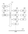
図1は、本発明の実施の形態に係るネットワーク機器としての画像形成装置のブロックである。 FIG. 1 is a block diagram of an image forming apparatus as a network device according to an embodiment of the present invention.
図1において、本画像形成装置は、ROM103に格納されているプログラムを実行するCPU101を備え、CPU101によって、システムバス111に接続される各デバイスを総括的に制御する。
In FIG. 1, the image forming apparatus includes a
また、RAM102は、CPU101の主メモリ、ワークエリア等として機能する。そして、デバイスの設定値を保存するバックアップRAMも構成される。CRTコントローラ(CRTC)104は、CRTディスプレイ(CRT)108の表示を制御する。CRTディスプレイ108を用いて、ユーザは画像形成装置において実行されているジョブ処理のステータスを確認したり、各種指示を入力したりすることができる。
The
ディスクコントローラ(DKC)105は、画像や様々なユーザデータを保存するハードディスク(HD)109を制御する。デバイスコントローラ(DVC)106は、プリンタ(DV)110を制御する。 A disk controller (DKC) 105 controls a hard disk (HD) 109 that stores images and various user data. A device controller (DVC) 106 controls the printer (DV) 110.
ネットワークインタフェースカード(NIC)107は、LAN112を介して、ネットワーク上の外部装置(例えば、PC(パーソナルコンピュータ)など)と画像形成装置との間の通信を制御する。
A network interface card (NIC) 107 controls communication between an external device (for example, a PC (personal computer)) on the network and the image forming apparatus via the
ここで、CPU101は、外部装置と画像形成装置との間で送受信されるパケットを監視する監視手段として機能する。また、CPU101は、監視するパケットの中から、外部装置からの処理要求に対して画像形成装置が送信した、処理要求を拒否する拒否パケットを検知する検知手段として機能する。さらに、CPU101は、外部装置からの処理要求の要求先のポート番号を認識し、認識されたポート番号に対応するアプリケーションを、処理要求の要求先のアプリケーションとして特定する特定手段として機能する。
Here, the
また、HD109は、所定のアプリケーションに対応するポート番号として初期設定されていたポート番号と、この所定のアプリケーションに対応するポート番号として現在設定されているポート番号とを関連付けて管理する管理手段として機能する。また、CPU101は、外部装置からの処理要求の要求先のアプリケーションがオン状態であるか、またはオフ状態であるかを判別する判別手段として機能する。さらに、CPU101は、外部装置からの処理要求を拒否する拒否パケットが画像形成装置から送信されたことを検知した場合に、この処理要求の要求先のアプリケーションを示す情報を含むエラー情報を、出力する出力手段として機能する。尚、CPU101がエラー情報を出力する場合は、例えば、表示手段として機能するCRTディスプレイ(CRT)108にエラー情報を表示させることにより、エラー情報を出力する。
The
尚、以上の詳細については、以降、順次説明する。 The details described above will be sequentially described below.
図2は、図1の画像形成装置が接続されるネットワーク通信システムの構成図である。 FIG. 2 is a configuration diagram of a network communication system to which the image forming apparatus of FIG. 1 is connected.
図2において、本ネットワーク通信システムは、PC201と複数の画像形成装置202、203がネットワーク204で接続されることで構築されている。各装置間の矢印はデータもしくは指示の流れを示している。
In FIG. 2, this network communication system is constructed by connecting a
PC201は、印刷ジョブを画像形成装置202、203に発行し、SNMPの監視プロトコル等を利用して、画像形成装置202、203のステータスを監視することができる。
The PC 201 can issue a print job to the
また、印刷プロトコルの1つであるRawを用いて印刷処理を実行するRawアプリケーションがそれぞれ、画像形成装置202ではオン状態、画像形成装置203ではオフ状態に設定されている。そこで、PC201から画像形成装置202のRawアプリケーションに対して印刷処理を要求すると(1)、画像形成装置202では印刷ジョブの受信が許可され、印刷処理が実行される(2)。一方、PC201から画像形成装置203のRawアプリケーションに対して印刷処理を要求すると(3)、画像形成装置203では、印刷ジョブの受信が拒否され、印刷処理が実行されない(4)。
In addition, the Raw application that executes printing using Raw, which is one of the printing protocols, is set to an on state in the
尚、本実施の形態では、Rawアプリケーションを用いた印刷処理に関して説明を行ったが、Raw以外の別のプロトコルを用いた印刷アプリケーションであっても構わない。また、SNMPに代表される監視系のアプリケーションであっても構わない。 In the present embodiment, the printing process using the Raw application has been described, but a printing application using another protocol other than Raw may be used. Further, it may be a monitoring system application represented by SNMP.
また、画像形成装置、PCとも、図2の構成に限定されるものではなく、それぞれ1または複数の組み合わせでも差し支えない。 Further, the image forming apparatus and the PC are not limited to the configuration shown in FIG. 2, and one or a plurality of combinations may be used.
図3は、図1の画像形成装置内部のポート管理テーブルの第1の例を示す図である。 FIG. 3 is a diagram illustrating a first example of a port management table in the image forming apparatus of FIG.
図3において、画像形成装置内部で使用する可能性のあるポート番号一覧301、ポート番号一覧301のポート番号ごとに、現在オン状態であるかオフ状態であるかを記述しているオン、オフ一覧302が示される。また、ポート番号一覧301のポート番号ごとにそれぞれ対応するアプリケーション名を記述しているアプリケーション名一覧303が示される。
In FIG. 3, the
尚、LPDやRaw等の既知のアプリケーションは、ポート番号、アプリケーション名は予め定められているため、固定情報として予め管理テーブルに保持しておく。また、オン、オフ一覧302のオフ、オン情報はNVRAMに保持されている各アプリケーションがオフ状態またはオン状態に設定されたことに応じて更新される。
In known applications such as LPD and Raw, the port number and application name are determined in advance, and are stored in the management table in advance as fixed information. Further, the off / on information of the on / off
尚、図3のポート管理テーブルは、予め固定情報として、管理テーブルを保持するとしたが、各アプリケーションから、使用するポート番号、アプリケーションのオフ情報/オン状態、アプリケーション名を自動的に登録させるような構成にしても構わない。 The port management table shown in FIG. 3 holds the management table as fixed information in advance. However, the port number to be used, the application off information / on state, and the application name are automatically registered from each application. You may make it a structure.
図4は、図1の画像形成装置内部のポート管理テーブルであって、アプリケーションによりポート番号を変更することを可能にした場合のポート管理テーブルを示す図である。 FIG. 4 is a port management table inside the image forming apparatus of FIG. 1 and shows the port management table when it is possible to change the port number by an application.
図4に示すポート管理テーブルには、現在設定されているポート番号(第2のポート番号)を示すポート番号一覧401、初期設定されていたポート番号(第1のポート番号)を示すポート番号一覧402の各情報がそれぞれ関連付けて管理されている。また、現在設定されているポート番号一覧401のポート番号ごとに、現在オン状態であるかオフ状態であるかを記述しているオン、オフ一覧403が示される。また、現在設定されているポート番号一覧401のポート番号ごとのアプリケーション名を記述しているアプリケーション名一覧404が示される。尚、ここでは初期設定されていたポート番号とは、工場出荷時に設定されているポート番号のことを示すが、その他の時点で設定されているポート番号を、初期設定のポート番号として管理するようにしても構わない。
The port management table shown in FIG. 4 includes a
図5は、図2のネットワーク通信システムのシーケンスの第1の実施の形態を示す図である。尚、図に示すフローチャートに沿って処理を実行するプログラムは、ROM103からRAM102にロードされ、CPU101の制御の下に実行される。
FIG. 5 is a diagram showing a first embodiment of a sequence of the network communication system in FIG. A program for executing processing according to the flowchart shown in the figure is loaded from the
PC201のIPアドレスは172.24.22.55に割り振られている。画像形成装置203は、Rawアプリケーションがオフ状態に設定されている。
The IP address of the
ステップS501では、PC201から送信された、TCP/IPプロトコルでのコネクション接続要求のSYNパケットを、画像形成装置203が受信する。尚、このSYNパケットは、Rawアプリケーションに対応するポート番号9100を要求先として送信される。ステップS502では、TCP/IPプロトコルで、コネクション接続拒否を示すRSTパケットが、画像形成装置203からPC201に送信される。
In step S <b> 501, the
画像形成装置203は、Rawアプリケーションがオフ状態に設定されているため、RSTパケットを返信している。尚、Rawアプリケーションがオン状態に設定されていれば、画像形成装置203は、ACKパケットを返信して、受信許可であることをPC201に通知する。
Since the raw application is set to the off state, the
尚、図5では、Rawアプリケーションに対して印刷要求を行う場合のシーケンスを示したが、LPD等の別の印刷プロトコルを用いる場合でも同様であり、また、SNMP等の監視プロトコルにも適用可能である。但し、SNMPを用いる場合は、UDPパケットを使用するため、SYNパケットでの要求ではなく、直接SNMPパケットでの要求がPC201から送信され、画像形成装置側は、パケットを返信しないことによりエラーであることを示す。
FIG. 5 shows a sequence when a print request is made to the Raw application, but the same applies when another print protocol such as LPD is used, and can also be applied to a monitoring protocol such as SNMP. is there. However, when SNMP is used, since a UDP packet is used, a request using a direct SNMP packet is transmitted from the
図6は、図1におけるCRTディスプレイ(CRT)108にエラー情報が表示された画面の一例を示す図である。 FIG. 6 is a diagram showing an example of a screen on which error information is displayed on the CRT display (CRT) 108 in FIG.
図6において、画面には、外部装置からの処理要求を受信した時刻601、処理要求の要求先のアプリケーション602、処理要求の要求元である外部装置のIPアドレス603が表示される。604には、処理要求を拒否したかどうかを示す情報が表示される。ここでは、処理要求が拒否された場合は「NG」と表示され、拒否されずに正常に処理が実行された場合は「OK」と表示される。
In FIG. 6, the screen displays a
更に、605には、処理要求が拒否された場合に、処理要求が拒否された原因を区別するための情報が表示される。尚、本実施形態では、処理要求の要求先のアプリケーションがオフ状態であることが原因で拒否された場合には「アプリOFF」と表示され、それ以外の原因により拒否された場合(「―」が表示される)と区別して表示している。 Further, 605 displays information for distinguishing the cause of the rejection of the processing request when the processing request is rejected. In the present embodiment, when the application requested for the processing request is rejected due to being in an off state, “application OFF” is displayed, and when the application is rejected for other reasons (“-”). Are displayed separately.
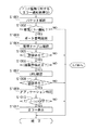
図7は、図1の画像形成装置によって実行されるパケット監視に対するエラー通知処理の手順の第1の実施の形態を示すフローチャートである。尚、図に示すフローチャートに沿って処理を実行するプログラムは、ROM103からRAM102にロードされ、CPU101の制御の下に実行される。
FIG. 7 is a flowchart showing a first embodiment of an error notification processing procedure for packet monitoring executed by the image forming apparatus of FIG. A program for executing processing according to the flowchart shown in the figure is loaded from the
図7において、ステップS701では、画像形成装置内のネットワーク監視モジュール(CPU101)が、PC201と画像形成装置の間で送受信されるパケットを監視する。
In FIG. 7, in step S701, the network monitoring module (CPU 101) in the image forming apparatus monitors packets transmitted and received between the
ステップS702では、ネットワーク監視モジュールが、PC201からのジョブ処理要求に対して画像形成装置が送信したRST(コネクション拒否)パケットを検知する。
In step S <b> 702, the network monitoring module detects an RST (connection rejection) packet transmitted by the image forming apparatus in response to a job processing request from the
ステップS702において、画像形成装置がRST(コネクション拒否)パケットを送信していれば、ステップS703へ進み、画像形成装置がRST(コネクション拒否)パケットを送出していなければ、終了する。 In step S702, if the image forming apparatus has transmitted an RST (connection rejection) packet, the process proceeds to step S703. If the image forming apparatus has not transmitted an RST (connection rejection) packet, the process ends.
尚、拒否パケットとは、PC201からのコネクション接続要求(処理要求)に対して、接続される側(画像形成装置側)からその接続を拒否することを示すパケットを意味する。また、処理要求を拒否する要因としては、アプリケーションがオフ状態である場合のほか、処理要求の要求元の外部装置のIPアドレスがフィルタリング対象の拒否IPアドレスとして登録されている場合がある。
The rejection packet means a packet indicating that the connection side (image forming apparatus side) rejects the connection in response to the connection connection request (processing request) from the
ステップS703では、処理要求の要求先のポート番号を識別する。ステップS704では、図3の管理テーブルを参照し、ステップS703で識別したポート番号が登録されているかどうかを検出する。 In step S703, the port number of the request destination of the processing request is identified. In step S704, the management table in FIG. 3 is referred to and it is detected whether the port number identified in step S703 is registered.
ステップS705では、上記ポート番号が登録されているかどうかを判別し、上記ポート番号が登録されていなければ終了し、上記ポート番号が登録されていれば、ステップS706へ進む。ステップS706では、図3の管理テーブルを参照し、ステップS703で識別したポート番号に対応するアプリケーションを特定する。 In step S705, it is determined whether or not the port number is registered. If the port number is not registered, the process ends. If the port number is registered, the process proceeds to step S706. In step S706, the application corresponding to the port number identified in step S703 is specified with reference to the management table of FIG.
ステップS707では、ステップS706で特定されたアプリケーションがオン状態であるか、またはオフ状態であるかを図3の管理テーブルを参照して判別する。そして、ステップS706で特定されたアプリケーションがオフ状態であれば、ステップS708へ進み、そうでなければ終了する。 In step S707, it is determined with reference to the management table of FIG. 3 whether the application identified in step S706 is in an on state or an off state. If the application identified in step S706 is off, the process proceeds to step S708, and if not, the process ends.
ステップS708では、ステップS706で特定されたアプリケーションの名称を含むエラー情報を、図6に示すように、CRT108の画面に表示する。
In step S708, error information including the name of the application specified in step S706 is displayed on the screen of the
尚、画像形成装置上で、ステップS704、S706、S707において、図3の管理テーブルに代えて、図4の管理テーブルを参照することも可能である。尚、図4の管理テーブルを参照する場合において、処理要求の要求先のポート番号が初期設定されていたポート番号である場合は、以下のようにしてもよい。即ち、処理要求の要求先のポート番号に関連付けて管理されている現在設定されているポート番号に対応するアプリケーションを、処理要求の要求先のアプリケーションとして特定するようにしてもよい。そして、特定されたアプリケーションの名称が、CRT108に表示される。
Note that in steps S704, S706, and S707 on the image forming apparatus, the management table in FIG. 4 can be referred to instead of the management table in FIG. In the case of referring to the management table of FIG. 4, when the port number of the request destination of the processing request is the port number that has been initially set, the following may be performed. In other words, the application corresponding to the currently set port number managed in association with the request destination port number of the processing request may be specified as the request destination application of the processing request. Then, the name of the identified application is displayed on the
また、ここでは、S706で特定されたアプリケーションがオフ状態でない、つまりオン状態であると判別された場合は処理を終了すると説明したが、実際には、処理要求の要求先のアプリケーションがオン状態に設定されている場合は、以下のように動作する。即ち、処理要求の要求先のアプリケーションがオン状態であるにも関わらず、処理要求が拒否される場合とは、例えば、処理要求の要求元のIPアドレスがフィルタリング対象の拒否IPアドレスとして登録されている場合が考えられる。このような場合は、処理要求の要求先のアプリケーションは、処理要求のパケットを受け取った上でその要求を拒否するかどうかを判断するので、CRT108の画面にはアプリケーションから直接通知される情報に基づくエラー情報が表示される。
In addition, here, it has been described that the process is terminated when it is determined that the application identified in S706 is not in the off state, that is, in the on state. However, in actuality, the application requested for the processing request is in the on state. If it is set, it operates as follows. That is, when the processing request is rejected even if the request destination application of the processing request is in the ON state, for example, the request source IP address of the processing request is registered as a filtering target rejection IP address. There may be cases. In such a case, the application to which the processing request is requested receives the processing request packet and determines whether to reject the request. Therefore, the screen of the
図8は、図1の画像形成装置内部のポート管理テーブルの第2の例を示す図である。 FIG. 8 is a diagram illustrating a second example of the port management table in the image forming apparatus of FIG.
図8において、画像形成内部で使用する可能性のあるポート番号一覧801、ポート番号一覧801のポート番号ごとに、現在オン状態であるかオフ状態であるかを記述しているオン、オフ一覧802が示される。また、ポート番号一覧801のポート番号ごとにそれぞれ対応するアプリケーション名を記述しているアプリケーション名一覧803、およびアプリケーションごとのサービスURL一覧804が示される。
In FIG. 8, an on / off
尚、図8の管理テーブルであるが、予め固定情報として、ポート番号を管理テーブルに記述してもよいし、自動的に、各アプリケーションから登録させるようにしても構わない。 Although it is the management table of FIG. 8, the port number may be described in the management table as fixed information in advance, or may be automatically registered from each application.
図9は、図2のネットワーク通信システムのシーケンスの第2の実施の形態を示す図である。尚、図に示すフローチャートに沿って処理を実行するプログラムは、ROM103からRAM102にロードされ、CPU101の制御の下に実行される。
FIG. 9 is a diagram showing a second embodiment of the sequence of the network communication system in FIG. A program for executing processing according to the flowchart shown in the figure is loaded from the
図9において、PC201のIPアドレスは172.24.22.55に割り振られている。画像形成装置202は、IPPアプリケーションがオフ状態に設定されている。
In FIG. 9, the IP address of the
ステップS901では、PC201から送信された、HTTPプロトコルでのコネクション接続要求を示すパケットを画像形成装置202が受信する。尚、このパケットは、IPPアプリケーションに対応するポート番号80を要求先として送信される。また、HTTPのヘッダには、サービスURL(URL情報)が含まれている。ステップS902では、TCP/IPプロトコルで、コネクション接続拒否を示す、RSTパケットが、画像形成装置202からPC201に送信される。
In step S901, the
画像処理装置202は、IPPアプリケーションがオフ状態に設定されているため、画像形成装置202は、TCP/IPプロトコルとして、RSTパケットをPC201に返信している。
Since the
尚、IPPアプリケーションがオン状態に設定されていれば、画像形成装置202は、HTTPの正常レスポンスをPC201に返信して、受信許可であることをPC201に通知する。
If the IPP application is set to the on state, the
尚、図9では、IPPアプリケーションに対して印刷要求を行う場合のシーケンスを記述したが、別のプロトコルに対応するアプリケーションでも同様であり適用可能である。 In FIG. 9, the sequence when a print request is made to the IPP application is described, but the same applies to an application corresponding to another protocol.
図10は、図1の画像形成装置によって実行されるパケット監視に対するエラー通知処理の手順の第2の実施の形態を示すフローチャートである。尚、図に示すフローチャートに沿って処理を実行するプログラムは、ROM103からRAM102にロードされ、CPU101の制御の下に実行される。
FIG. 10 is a flowchart showing a second embodiment of the error notification processing procedure for packet monitoring executed by the image forming apparatus of FIG. A program for executing processing according to the flowchart shown in the figure is loaded from the
図10において、ステップS1001では、画像形成装置内のネットワーク監視モジュール(CPU101)が、PC201と画像形成装置の間で送受信されるパケットを監視する。
In FIG. 10, in step S1001, the network monitoring module (CPU 101) in the image forming apparatus monitors packets transmitted and received between the
ステップS1002では、ネットワーク監視モジュールが、PC201からのジョブ処理要求に対して画像形成装置が送信したRST(コネクション拒否)パケットを検知する。
In step S1002, the network monitoring module detects an RST (connection rejection) packet transmitted by the image forming apparatus in response to a job processing request from the
ステップS1002において、画像形成装置がRST(コネクション拒否)パケットを送信していれば、ステップS1003へ進み、画像形成装置がRST(コネクション拒否)パケットを送出していなければ、終了する。 In step S1002, if the image forming apparatus has transmitted an RST (connection rejection) packet, the process proceeds to step S1003. If the image forming apparatus has not transmitted an RST (connection rejection) packet, the process ends.
ステップS1003では、処理要求の要求先のポート番号を識別する。ステップS1004では、図8の管理テーブルを参照し、ステップS1003で識別したポート番号が登録されているかを検出する。 In step S1003, the port number of the request destination of the processing request is identified. In step S1004, the management table in FIG. 8 is referenced to detect whether the port number identified in step S1003 is registered.
ステップS1005では、上記ポート番号が登録されているかどうかを判別し、上記ポート番号が登録されていれば、ステップS1006へ進み、そうでなければ終了する。 In step S1005, it is determined whether or not the port number is registered. If the port number is registered, the process proceeds to step S1006; otherwise, the process ends.
ステップS1006では、該当するポート番号に対して、複数のアプリケーション対応付けて登録されているかどうかを判別し、複数のアプリケーションが登録されていれば、ステップS1007へ進む。一方、複数のアプリケーションが登録されておらず、1つのアプリケーションが登録されている場合は、図7のステップS706へ進む。 In step S1006, it is determined whether or not a corresponding port number is registered in association with a plurality of applications. If a plurality of applications are registered, the process proceeds to step S1007. On the other hand, if a plurality of applications are not registered and one application is registered, the process proceeds to step S706 in FIG.
ステップS1007では、PC201から通知されるサービスURLを確認し、ステップS1008で、PC201から通知されたサービスURLと一致するサービスURLが管理テーブル上に存在すれば、ステップS1009へ進み、そうでなければ終了する。PC201から通知されたサービスURLと一致するサービスURLが存在しなければ終了する。
In step S1007, the service URL notified from the
ステップS1009では、図8の管理テーブルを参照し、ステップS1007で確認したURLに関連付けられたアプリケーションを特定する。 In step S1009, the application associated with the URL confirmed in step S1007 is specified with reference to the management table of FIG.
ステップS1010では、ステップS1009のポート番号に関連付けられたアプリケーションがオン状態であるか、またはオフ状態であるかを判別する。そして、ステップS1007のURLに関連付けられたアプリケーションがオフ状態であれば、ステップS1011へ進み、そうでなければ終了する。 In step S1010, it is determined whether the application associated with the port number in step S1009 is on or off. If the application associated with the URL in step S1007 is off, the process proceeds to step S1011. Otherwise, the process ends.
ステップS1011では、ステップS1009で特定されたアプリケーションの名称を含むエラー情報を、図6に示すように、CRT108の画面に表示する。
In step S1011, error information including the name of the application specified in step S1009 is displayed on the screen of the
(その他の実施形態)
以上、実施形態例を詳述したが、本発明は、例えば、システム、装置、方法、プログラム若しくは記憶媒体(記録媒体)等としての実施態様をとることが可能である。具体的には、複数の機器から構成されるシステムに適用しても良いし、また、一つの機器からなる装置に適用しても良い。
(Other embodiments)
Although the embodiment has been described in detail above, the present invention can take an embodiment as a system, apparatus, method, program, storage medium (recording medium), or the like. Specifically, the present invention may be applied to a system composed of a plurality of devices, or may be applied to an apparatus composed of a single device.
尚、本発明は、前述した実施形態の機能を実現するソフトウェアのプログラム(実施形態では図に示すフローチャートに対応したプログラム)を、システムあるいは装置に直接あるいは遠隔から供給する。そして、そのシステムあるいは装置のコンピュータが該供給されたプログラムコードを読み出して実行することによっても達成される場合を含む。 In the present invention, a software program (in the embodiment, a program corresponding to the flowchart shown in the drawing) that realizes the functions of the above-described embodiments is directly or remotely supplied to a system or apparatus. In addition, this includes a case where the system or the computer of the apparatus is also achieved by reading and executing the supplied program code.
従って、本発明の機能処理をコンピュータで実現するために、該コンピュータにインストールされるプログラムコード自体も本発明を実現するものである。つまり、本発明は、本発明の機能処理を実現するためのコンピュータプログラム自体も含まれる。 Accordingly, since the functions of the present invention are implemented by computer, the program code installed in the computer also implements the present invention. In other words, the present invention includes a computer program itself for realizing the functional processing of the present invention.
その場合、プログラムの機能を有していれば、オブジェクトコード、インタプリタにより実行されるプログラム、OSに供給するスクリプトデータ等の形態であっても良い。 In that case, as long as it has the function of a program, it may be in the form of object code, a program executed by an interpreter, script data supplied to the OS, or the like.
プログラムを供給するためのコンピュータ読み取り可能な記録媒体としては、例えば、以下のようなものがある。フロッピー(登録商標)ディスク、ハードディスク、光ディスク、光磁気ディスク、MO、CD−ROM、CD−R、CD−RW、磁気テープ、不揮発性のメモリカード、ROM、DVD(DVD−ROM,DVD−R)。 Examples of the computer-readable recording medium for supplying the program include the following. Floppy (registered trademark) disk, hard disk, optical disk, magneto-optical disk, MO, CD-ROM, CD-R, CD-RW, magnetic tape, nonvolatile memory card, ROM, DVD (DVD-ROM, DVD-R) .
その他、プログラムの供給方法としては、クライアントコンピュータのブラウザを用いてインターネットのホームページからハードディスク等の記録媒体にダウンロードすることによっても供給できる。即ち、ホームページに接続し、該ホームページから本発明のコンピュータプログラムそのもの、もしくは圧縮され自動インストール機能を含むファイルをダウンロードする。また、本発明のプログラムを構成するプログラムコードを複数のファイルに分割し、それぞれのファイルを異なるホームページからダウンロードすることによっても実現可能である。つまり、本発明の機能処理をコンピュータで実現するためのプログラムファイルを複数のユーザに対してダウンロードさせるWWWサーバも、本発明に含まれるものである。 As another program supply method, the program can be supplied by downloading it from a homepage on the Internet to a recording medium such as a hard disk using a browser of a client computer. That is, it connects to a home page and downloads the computer program itself of the present invention or a compressed file including an automatic installation function from the home page. It can also be realized by dividing the program code constituting the program of the present invention into a plurality of files and downloading each file from a different homepage. That is, a WWW server that allows a plurality of users to download a program file for realizing the functional processing of the present invention on a computer is also included in the present invention.
また、本発明のプログラムを暗号化してCD−ROM等の記憶媒体に格納してユーザに配布する。そして、所定の条件をクリアしたユーザに対し、インターネットを介してホームページから暗号化を解く鍵情報をダウンロードさせる。そして、その鍵情報を使用することにより暗号化されたプログラムを実行してコンピュータにインストールさせて実現することも可能である。 Further, the program of the present invention is encrypted, stored in a storage medium such as a CD-ROM, and distributed to users. Then, the user who has cleared the predetermined condition is allowed to download key information for decryption from the homepage via the Internet. It is also possible to execute the encrypted program by using the key information and install the program on a computer.
また、コンピュータが、読み出したプログラムを実行することによって、前述した実施形態の機能が実現される。その他にも、そのプログラムの指示に基づき、コンピュータ上で稼動しているOSなどが、実際の処理の一部または全部を行い、その処理によっても前述した実施形態の機能が実現され得る。 Further, the functions of the above-described embodiments are realized by the computer executing the read program. In addition, the function of the above-described embodiment can be realized by an OS running on the computer based on an instruction of the program and performing part or all of the actual processing.
さらに、記録媒体から読み出されたプログラムが、コンピュータに挿入された機能拡張ボードやコンピュータに接続された機能拡張ユニットに備わるメモリに書き込まれた後にも前述した実施形態の機能が実現される。即ち、そのプログラムの指示に基づき、その機能拡張ボードや機能拡張ユニットに備わるCPUなどが実際の処理の一部または全部を行うことによっても前述した実施形態の機能が実現される。 Further, the functions of the above-described embodiments are realized even after the program read from the recording medium is written in a memory provided in a function expansion board inserted into the computer or a function expansion unit connected to the computer. That is, the functions of the above-described embodiments are realized by performing part or all of the actual processing by the CPU or the like provided in the function expansion board or function expansion unit based on the instructions of the program.
101 CPU
102 RAM
103 ROM
104 CRTC
105 DKC
106 DVC
107 NIC
108 CRT
109 HD
110 DV
101 CPU
102 RAM
103 ROM
104 CRTC
105 DKC
106 DVC
107 NIC
108 CRT
109 HD
110 DV
Claims (8)
前記外部装置からの処理要求を受け付けたポートのポート番号とアプリケーションとを対応付けて、前記アプリケーションが動作している状態または動作していない状態であるかを管理する管理手段と、
前記外部装置と前記ネットワーク機器との間で送受信されるパケットを監視する監視手段と、
前記監視手段で監視される前記パケットに、前記ネットワーク機器から前記外部装置に対して送信され前記外部装置からの処理要求を拒否する拒否パケットがあると、前記外部装置からの処理要求が拒否されたことを検知する検知手段と、
前記検知手段により前記外部装置からの処理要求が拒否されたことが検知された場合に、当該拒否された処理要求に含まれるポート番号に対応するアプリケーションを特定する特定手段と、
前記特定手段により特定されたアプリケーションが動作している状態であるか、または動作していない状態であるかを判定する判定手段と、
前記検知手段により前記外部装置からの処理要求が拒否されたことが検知された場合に、前記判定手段により、前記特定手段により特定されたアプリケーションが動作していない状態であると判定されると、当該特定されたアプリケーションを示す情報を含むエラー情報を出力する出力手段と、
を備えることを特徴とするネットワーク機器。 A network device connected to an external device via a network and accepting a processing request from the external device,
A management unit that associates a port number of a port that has received a processing request from the external device with an application, and manages whether the application is operating or not operating;
Monitoring means for monitoring packets transmitted and received between the external device and the network device;
If the packet monitored by the monitoring unit includes a rejection packet that is transmitted from the network device to the external device and rejects a processing request from the external device, the processing request from the external device is rejected. Detection means for detecting
A specifying unit that specifies an application corresponding to a port number included in the rejected processing request when the detection unit detects that the processing request from the external device is rejected;
Determining means for determining whether the application specified by the specifying means is operating or not operating;
When it is detected by the detection means that the processing request from the external device has been rejected, the determination means determines that the application specified by the specification means is not in operation. Output means for outputting error information including information indicating the identified application;
A network device comprising:
前記出力手段は、前記外部装置からの処理要求が、前記特定されたアプリケーションが動作していない状態であることが原因で拒否されたかまたはそれ以外の原因により拒否されたかを区別して前記エラー情報を出力することを特徴とする請求項1に記載のネットワーク機器。 When the detection unit detects that the processing request from the external device has been rejected by the detection unit, the output unit also provides error information even when the application specified by the specification unit is operating. Output
The output means distinguishes whether the processing request from the external device has been rejected because the specified application is not in operation or has been rejected due to other reasons. The network device according to claim 1 , wherein the network device outputs the network device.
前記特定手段は、前記処理要求を受け付けたポートのポート番号が前記第1のポート番号である場合に、前記管理手段により当該第1のポート番号に関連付けて管理されている前記第2のポート番号に対応するアプリケーションを、前記外部装置から処理要求を受け付けたポートのポート番号に対応するアプリケーションとして特定することを特徴とする請求項1または2に記載のネットワーク機器。 The management means associates and manages the first port number initially set as the port number corresponding to the application and the second port number currently set as the port number corresponding to the application. And
When the port number of the port that has received the processing request is the first port number, the specifying unit manages the second port number managed in association with the first port number by the management unit. 3. The network device according to claim 1, wherein the network device is identified as an application corresponding to a port number of a port that has received a processing request from the external device.
前記特定手段は、前記外部装置から処理要求を受け付けたポートのポート番号に対して、複数のアプリケーションが対応している場合は、さらに前記外部装置から通知されるURL情報を用いて前記処理要求の要求先のアプリケーションを特定することを特徴とする請求項1から3のいずれか1項に記載のネットワーク機器。 The management means manages URL information in association with the application,
When the plurality of applications correspond to the port number of the port that has received the processing request from the external device, the specifying unit further uses the URL information notified from the external device to specify the processing request. network device according to any one of claims 1 to 3, characterized in that to identify the requested application.
前記出力手段は、前記エラー情報を前記表示手段に表示させることにより、当該エラー情報を出力することを特徴とする請求項1から4のいずれか1項に記載のネットワーク機器。 It further comprises display means for displaying the error information,
Said output means, said by displaying error information on the display means, the network device according to claim 1, any one of 4 and outputs the error information.
前記処理要求の要求先のポート番号とアプリケーションとを対応付けて、前記アプリケーションが動作している状態または動作していない状態であるかを管理する管理工程と、
前記外部装置と前記ネットワーク機器との間で送受信されるパケットを監視する監視工程と、
前記監視工程で監視される前記パケットに、前記ネットワーク機器から前記外部装置に対して送信され前記外部装置からの処理要求を拒否する拒否パケットがあると、前記外部装置からの処理要求が拒否されたことを検知する検知工程と、
前記検知工程により前記外部装置からの処理要求が拒否されたことが検知された場合に、当該拒否された処理要求に含まれるポート番号に対応するアプリケーションを特定する特定工程と、
前記特定工程により特定されたアプリケーションが動作している状態であるか、または動作していない状態であるかを判定する判定工程と、
前記検知工程により前記外部装置からの処理要求が拒否されたことが検知された場合に、前記判定工程により、前記特定工程により特定されたアプリケーションが動作していない状態であると判定されると、当該特定されたアプリケーションを示す情報を含むエラー情報を出力する出力工程と、
を備えることを特徴とするネットワーク機器の制御方法。 A method for controlling a network device connected to an external device via a network and receiving a processing request from the external device,
A management step of associating the port number of the request destination of the processing request with an application and managing whether the application is operating or not operating,
A monitoring step of monitoring packets transmitted and received between the external device and the network device;
If the packet monitored in the monitoring step includes a rejection packet that is transmitted from the network device to the external device and rejects a processing request from the external device, the processing request from the external device is rejected. A detection process for detecting this,
A specific step of identifying an application corresponding to a port number included in the rejected processing request when it is detected that the processing request from the external device is rejected by the detecting step;
A determination step of determining whether the application identified by the identification step is operating or not operating;
When it is detected by the detection step that the processing request from the external device has been rejected, the determination step determines that the application specified by the specific step is not in operation. An output step of outputting error information including information indicating the identified application;
A method for controlling a network device, comprising:
Priority Applications (2)
| Application Number | Priority Date | Filing Date | Title |
|---|---|---|---|
| JP2008030421A JP5213474B2 (en) | 2008-02-12 | 2008-02-12 | Network device, control method thereof, and program |
| US12/365,020 US8689057B2 (en) | 2008-02-12 | 2009-02-03 | Network apparatus, control method therefor, and storage medium |
Applications Claiming Priority (1)
| Application Number | Priority Date | Filing Date | Title |
|---|---|---|---|
| JP2008030421A JP5213474B2 (en) | 2008-02-12 | 2008-02-12 | Network device, control method thereof, and program |
Publications (3)
| Publication Number | Publication Date |
|---|---|
| JP2009194441A JP2009194441A (en) | 2009-08-27 |
| JP2009194441A5 JP2009194441A5 (en) | 2011-03-31 |
| JP5213474B2 true JP5213474B2 (en) | 2013-06-19 |
Family
ID=40939924
Family Applications (1)
| Application Number | Title | Priority Date | Filing Date |
|---|---|---|---|
| JP2008030421A Active JP5213474B2 (en) | 2008-02-12 | 2008-02-12 | Network device, control method thereof, and program |
Country Status (2)
| Country | Link |
|---|---|
| US (1) | US8689057B2 (en) |
| JP (1) | JP5213474B2 (en) |
Families Citing this family (12)
| Publication number | Priority date | Publication date | Assignee | Title |
|---|---|---|---|---|
| JP4976672B2 (en) * | 2005-09-13 | 2012-07-18 | キヤノン株式会社 | Network device apparatus, data processing method, and computer program |
| JP5451295B2 (en) * | 2009-09-30 | 2014-03-26 | キヤノン株式会社 | Image forming apparatus, image forming control method and program |
| JP5672899B2 (en) * | 2010-09-27 | 2015-02-18 | 日本電気株式会社 | Information processing apparatus, information processing system, message processing method, and message processing program |
| CN102892135B (en) * | 2012-10-08 | 2015-06-10 | 中兴通讯股份有限公司 | Release management method and device of mobile terminal network ports |
| JP6164823B2 (en) * | 2012-11-30 | 2017-07-19 | キヤノン株式会社 | Printing device |
| JP6238528B2 (en) * | 2013-02-22 | 2017-11-29 | キヤノン株式会社 | Printing device |
| JP6165096B2 (en) * | 2014-04-15 | 2017-07-19 | キヤノン株式会社 | Printing apparatus, setting method, and program |
| JP7180097B2 (en) * | 2018-03-29 | 2022-11-30 | ブラザー工業株式会社 | Communication device and computer program for the communication device |
| JP6748754B2 (en) * | 2019-04-04 | 2020-09-02 | キヤノン株式会社 | Printing device, setting method, and program |
| JP6919034B2 (en) * | 2019-04-04 | 2021-08-11 | キヤノン株式会社 | Printing device, setting method and program |
| JP7155355B2 (en) * | 2020-07-27 | 2022-10-18 | キヤノン株式会社 | Printing device, method and program |
| JP7254999B2 (en) * | 2020-07-27 | 2023-04-10 | キヤノン株式会社 | Printing device, method and program |
Family Cites Families (7)
| Publication number | Priority date | Publication date | Assignee | Title |
|---|---|---|---|---|
| US20020089687A1 (en) * | 2001-01-11 | 2002-07-11 | Ferlitsch Andrew Rodney | Methods and systems for print-processor-based printer status detection and print task distribution |
| JP3596478B2 (en) * | 2001-02-28 | 2004-12-02 | 日本電気株式会社 | Traffic classification device and traffic classification method |
| US7035289B2 (en) * | 2002-05-03 | 2006-04-25 | Cedar Point Communications | Communications switching architecture |
| JP4183561B2 (en) | 2003-06-02 | 2008-11-19 | 日立オムロンターミナルソリューションズ株式会社 | Automatic transaction device that detects unauthorized access and unauthorized programs |
| KR20050054681A (en) * | 2003-12-05 | 2005-06-10 | 삼성전자주식회사 | Network image forming apparatus having a function of error notice and operation control method thereof |
| JP2005310105A (en) * | 2004-03-22 | 2005-11-04 | Seiko Epson Corp | Remote monitoring system, remote monitoring method and remote monitoring program |
| US7779309B2 (en) * | 2007-11-07 | 2010-08-17 | Workman Nydegger | Correlating complex errors with generalized end-user tasks |
-
2008
- 2008-02-12 JP JP2008030421A patent/JP5213474B2/en active Active
-
2009
- 2009-02-03 US US12/365,020 patent/US8689057B2/en active Active
Also Published As
| Publication number | Publication date |
|---|---|
| US8689057B2 (en) | 2014-04-01 |
| JP2009194441A (en) | 2009-08-27 |
| US20090204857A1 (en) | 2009-08-13 |
Similar Documents
| Publication | Publication Date | Title |
|---|---|---|
| JP5213474B2 (en) | Network device, control method thereof, and program | |
| US9075627B2 (en) | Server connected to image forming apparatus and client, client, and method of remotely installing driver of image forming apparatus | |
| JP4936549B2 (en) | Server device, management system, management method, storage medium, program | |
| US9268628B2 (en) | Image forming apparatus, control method for image forming apparatus, and storage medium | |
| JP6025435B2 (en) | Image forming apparatus, information processing apparatus, and control method thereof | |
| JP6272117B2 (en) | Printing system, printing server, printing control method and program | |
| JP6881949B2 (en) | Management system and control method | |
| US11533218B2 (en) | Communication method and control method in information processing apparatus | |
| US7751425B2 (en) | Management device, management method, computer readable medium and computer data signal | |
| JP4714173B2 (en) | IT resource configuration change detection method and configuration management apparatus | |
| KR100547117B1 (en) | Method and apparatus for remote control a network electron device | |
| US20130286434A1 (en) | Image forming apparatus having network interface and interface enabling to connect peripheral device | |
| US20180062961A1 (en) | Network system, device management method, network device, control method thereof, and non-transitory computer-readable medium | |
| JP5657062B2 (en) | Image forming apparatus, image forming apparatus control method, and program | |
| JP6349733B2 (en) | Information processing apparatus, recovery support method, recovery support program, recovery support system, and recovery support server | |
| JP4725066B2 (en) | Printing device monitoring system, network board, and printing device monitoring method | |
| JP6021651B2 (en) | Management system, management method, and computer program | |
| JP4227564B2 (en) | Management apparatus, information processing method, and program | |
| JP5014040B2 (en) | Gateway device, gateway method of gateway device, and gateway program | |
| US8270017B2 (en) | Network card device for determining permissibility for processing data from a data source and method of controlling the same | |
| JP4952531B2 (en) | Recording apparatus, recording program, and recording method | |
| JP2005339106A (en) | Printer address monitoring system | |
| US20090049533A1 (en) | User authentication method and apparatus | |
| JP4174411B2 (en) | Job management apparatus, job management method, and job management program | |
| JP6669382B2 (en) | Device device, information processing method and program |
Legal Events
| Date | Code | Title | Description |
|---|---|---|---|
| A521 | Written amendment |
Free format text: JAPANESE INTERMEDIATE CODE: A523 Effective date: 20110209 |
|
| A621 | Written request for application examination |
Free format text: JAPANESE INTERMEDIATE CODE: A621 Effective date: 20110209 |
|
| A977 | Report on retrieval |
Free format text: JAPANESE INTERMEDIATE CODE: A971007 Effective date: 20120606 |
|
| A131 | Notification of reasons for refusal |
Free format text: JAPANESE INTERMEDIATE CODE: A131 Effective date: 20120611 |
|
| A521 | Written amendment |
Free format text: JAPANESE INTERMEDIATE CODE: A523 Effective date: 20120808 |
|
| TRDD | Decision of grant or rejection written | ||
| A01 | Written decision to grant a patent or to grant a registration (utility model) |
Free format text: JAPANESE INTERMEDIATE CODE: A01 Effective date: 20130129 |
|
| A61 | First payment of annual fees (during grant procedure) |
Free format text: JAPANESE INTERMEDIATE CODE: A61 Effective date: 20130226 |
|
| R151 | Written notification of patent or utility model registration |
Ref document number: 5213474 Country of ref document: JP Free format text: JAPANESE INTERMEDIATE CODE: R151 |
|
| FPAY | Renewal fee payment (event date is renewal date of database) |
Free format text: PAYMENT UNTIL: 20160308 Year of fee payment: 3 |