JP5212157B2 - Image reading apparatus, failure detection method, program, and recording medium - Google Patents
Image reading apparatus, failure detection method, program, and recording medium Download PDFInfo
- Publication number
- JP5212157B2 JP5212157B2 JP2009030127A JP2009030127A JP5212157B2 JP 5212157 B2 JP5212157 B2 JP 5212157B2 JP 2009030127 A JP2009030127 A JP 2009030127A JP 2009030127 A JP2009030127 A JP 2009030127A JP 5212157 B2 JP5212157 B2 JP 5212157B2
- Authority
- JP
- Japan
- Prior art keywords
- halation
- image reading
- light
- reflected
- light source
- Prior art date
- Legal status (The legal status is an assumption and is not a legal conclusion. Google has not performed a legal analysis and makes no representation as to the accuracy of the status listed.)
- Expired - Fee Related
Links
Images


Description
本発明は、画像読取装置、故障検知方法、プログラム及び記録媒体に関し、特に発光素子の故障を検知する画像読取装置、故障検知方法、プログラム及び記録媒体に関する。 The present invention relates to an image reading apparatus, a failure detection method, a program, and a recording medium, and more particularly, to an image reading apparatus, a failure detection method, a program, and a recording medium that detect a failure of a light emitting element.
CCD(Charge Coupled Devices)、CMOS(Complementary Metal Oxide Semiconductor)等の撮像手段で撮像した原稿面からの反射光に基づいて、その原稿面の画像を読み取る読取装置が知られている。原稿静止型の画像読取装置では、コンタクトガラス上に載置された画像読取対象物たる原稿に対してキャリッジを移動させながら光を照射する。 2. Description of the Related Art A reading device that reads an image on a document surface based on reflected light from the document surface imaged by an imaging unit such as a CCD (Charge Coupled Devices) or a CMOS (Complementary Metal Oxide Semiconductor) is known. In a stationary document type image reading apparatus, light is emitted while moving a carriage on a document which is an image reading object placed on a contact glass.
スキャナ用光源としては、キセノンランプや冷陰極管が使用され、主走査方向への線光源として原稿読み取り面を照射していた。しかしながら、キセノンランプ等は消費電力が大きく、光源の立ち上がりスピードが遅く、また、発熱量も多いため、近年の省エネルギー化、画像読取装置の長寿命化等の要求に十分に応えることができない。そのため、キセノンランプ等よりも消費電力が小さく、光源の立ち上がりのスピードが速く、発熱量が小さい光源が望まれている。このような光源として、例えば白色光出力可能な白色LED(Light Emitting Diode)が利用可能である。LEDは一般にキセノンランプに比べて照射強度が小さく、点光源である。そのためLEDを主走査方向に複数個アレイ状に並べる事で線光源として採用できる(特許文献1、2参照)。 A xenon lamp or a cold cathode tube is used as a light source for the scanner, and the original reading surface is irradiated as a linear light source in the main scanning direction. However, a xenon lamp or the like consumes a large amount of power, has a slow light source start-up speed, and generates a large amount of heat. Therefore, it cannot sufficiently meet the recent demands for energy saving, long life of the image reading apparatus, and the like. Therefore, there is a demand for a light source that consumes less power than a xenon lamp or the like, has a fast light source start-up speed, and generates a small amount of heat. As such a light source, for example, a white LED (Light Emitting Diode) capable of outputting white light can be used. An LED generally has a lower irradiation intensity than a xenon lamp and is a point light source. Therefore, it can be adopted as a line light source by arranging a plurality of LEDs in an array in the main scanning direction (see Patent Documents 1 and 2).
しかしながら、アレイを構成する個々のLEDのうちの一つが故障した場合であっても、白色LEDアレイ全体を交換する必要が生じ、装置の製造コスト及び装置の保守並びに維持に要するコストが高くなってしまうという欠点があった。 However, even if one of the individual LEDs that make up the array fails, the entire white LED array must be replaced, increasing the cost of manufacturing and maintaining and maintaining the device. There was a drawback of end.
そこで、LED自体の故障検出と、故障箇所に隣接するLEDの光量を上げる事により画像への影響を軽減するという目的で、読み取り光源として1列に配列したLED光源を順次点灯していき、原稿対象からの反射光を読み取りデバイスで検出した結果よりLEDの故障検知手段を備えた画像読取装置が提案されている(例えば特許文献3参照)。 Therefore, for the purpose of reducing the influence on the image by detecting the failure of the LED itself and increasing the light quantity of the LED adjacent to the failure location, the LED light sources arranged in a row as the reading light source are sequentially turned on. From the result of detecting reflected light from a target with a reading device, an image reading apparatus provided with LED failure detection means has been proposed (see, for example, Patent Document 3).
しかしながら、上述した故障検知手段では、LEDを順次点灯するために故障検出に時間を要する、制御が複雑、という問題があり、個体不良を検出するにはハードの追加が必要である等の問題があった。さらに、任意のタイミングで検出することができないため、スキャン動作の過程で故障を検出する事は困難であった。 However, the above-described failure detection means has problems that it takes time to detect the failure in order to sequentially turn on the LEDs, that the control is complicated, and that additional hardware is required to detect individual defects. there were. Furthermore, since it cannot be detected at an arbitrary timing, it is difficult to detect a failure in the course of the scanning operation.
本発明はこのような状況に鑑みてなされたものであり、発光素子の故障を検知することを目的とする。 The present invention has been made in view of such a situation, and an object thereof is to detect a failure of a light emitting element.
請求項1記載の画像読取装置は、複数の発光素子が1列又は複数列に配置された光源部と、前記光源部から照射された光が画像読取対象物で反射した反射光に基づいて画像読取対象物を撮像する撮像手段と、を備える画像読取装置であって、前記光源部から照射された光が反射した際にハレーションを生じさせる構造の被読取面を設けたハレーション発生手段と、前記光源部から照射された光が前記ハレーション発生手段に設けられた被読取面に反射した反射光を電荷に変え電気信号として前記撮像手段から出力されたデータであるハレーションデータのうち、画像信号レベルが予め定めた規定値に満たない箇所があるか否か判断することで、前記発光素子の故障を検知する故障検知手段と、を備えることを特徴とする。 The image reading apparatus according to claim 1, wherein an image is based on a light source unit in which a plurality of light emitting elements are arranged in one or a plurality of rows, and reflected light reflected from an image reading object by light emitted from the light source unit. An image reading device including an image pickup unit that picks up an image of a reading object, the halation generation unit including a read surface having a structure that generates halation when the light emitted from the light source unit is reflected, and Of the halation data, which is the data output from the imaging means as an electric signal, the reflected light reflected from the read surface provided in the halation generating means is reflected by the light emitted from the light source unit, and the image signal level is the data output from the imaging means. And a failure detecting means for detecting a failure of the light emitting element by determining whether or not there is a portion that does not satisfy a predetermined value.
本発明に係る故障検知方法は、複数の発光素子が1列又は複数列に配置された光源部と、前記光源部から照射された光が画像読取対象物で反射した反射光に基づいて画像読取対象物を撮像する撮像手段と、を備える画像読取装置における故障検知方法であって、前記光源部から光を照射するステップと、前記光源部から照射された光が反射した際にハレーションを生じさせる構造の被読取面を設けたハレーション発生部に照射され、前記ハレーション発生手段に設けられた被読取面に反射した反射光を電荷に変え電気信号として前記撮像手段からデータを出力するステップと、前記ハレーション発生手段に設けられた被読取面に反射した反射光を電荷に変え電気信号として前記撮像手段から出力されたデータであるハレーションデータのうち、画像信号レベルが予め定めた規定値に満たない箇所があるか否か判断することで、前記発光素子の故障を検知するステップと、を備えることを特徴とする。 The failure detection method according to the present invention includes a light source unit in which a plurality of light emitting elements are arranged in one or a plurality of columns, and image reading based on reflected light reflected from an image reading object by light emitted from the light source unit. A failure detection method in an image reading apparatus including an imaging unit that images an object, the step of irradiating light from the light source unit, and halation when light emitted from the light source unit is reflected A step of outputting data from the imaging means as an electrical signal by converting the reflected light reflected on the read surface provided in the halation generation means into a charge, which is irradiated to the halation generation section provided with the read surface of the structure; and Of the halation data, which is the data output from the imaging means as an electric signal by converting the reflected light reflected on the surface to be read provided in the halation generating means into electric charges By image signal level to determine whether there is a portion less than a predetermined specified value, characterized in that it comprises the steps of: detecting a failure of the light emitting element.
本発明に係る故障検知プログラムは、複数の発光素子が1列又は複数列に配置された光源部と、前記光源部から照射された光が画像読取対象物で反射した反射光に基づいて画像読取対象物を撮像する撮像手段と、を備える画像読取装置における故障検知プログラムであって、前記光源部から光を照射する処理と、前記光源部から照射された光が反射した際にハレーションを生じさせる構造の被読取面を設けたハレーション発生部に照射され、前記ハレーション発生手段に設けられた被読取面に反射した反射光を電荷に変え電気信号として前記撮像手段からデータを出力する処理と、前記ハレーション発生手段に設けられた被読取面に反射した反射光を電荷に変え電気信号として前記撮像手段から出力されたデータであるハレーションデータのうち、画像信号レベルが予め定めた規定値に満たない箇所があるか否か判断することで、前記発光素子の故障を検知する処理と、をコンピュータに実行させることを特徴とする。 The failure detection program according to the present invention reads an image based on a light source unit in which a plurality of light emitting elements are arranged in one or a plurality of rows, and reflected light reflected from an image reading object by light emitted from the light source unit. A failure detection program for an image reading apparatus including an imaging unit that images an object, wherein a process of irradiating light from the light source unit and halation is generated when light emitted from the light source unit is reflected A process of outputting data from the imaging means as an electrical signal by converting the reflected light reflected on the read surface provided in the halation generation means into an electric charge, which is irradiated to the halation generation section provided with the read surface of the structure; The reflected light reflected from the surface to be read provided in the halation generating means is converted into electric charges, and the halation data, which is data output from the imaging means as an electrical signal, is output. Chi, that image signal level to determine whether there is a portion less than a predetermined specified value, characterized in that to execute a process of detecting a failure of the light emitting device, to the computer.
本発明に係る記録媒体は、上記本発明の故障検知プログラムの処理を記録するコンピュータ読取り可能な記録媒体である。 The recording medium according to the present invention is a computer-readable recording medium for recording the process of the failure detection program of the present invention.
本発明によれば、ハレーションを強制的に発生させることで取得したハレーションデータから、発光素子の故障を検知することが可能となる。 According to the present invention, it is possible to detect a failure of a light emitting element from halation data acquired by forcibly generating halation.
以下に、本発明の実施形態について図面を用いて詳細に説明する。なお、以下に述べる実施形態は、本発明の好適な実施形態であるから、技術的に好ましい種々の限定が付されているが、本発明の範囲は、以下の説明において特に本発明を限定する旨の記載がない限り、これらの態様に限られるものではない。 Embodiments of the present invention will be described below in detail with reference to the drawings. The embodiments described below are preferred embodiments of the present invention, and thus various technically preferable limitations are given. However, the scope of the present invention is particularly limited in the following description. As long as there is no description of the effect, it is not restricted to these aspects.
なお本明細書においては、発光素子の一例としてLED、撮像手段の一例としてCCD(Charge Coupled Device)、ハレーション発生手段の一例としてハレーション発生部24、故障検知手段の一例として故障検知部10、を用いて説明する。
In this specification, an LED is used as an example of a light emitting element, a CCD (Charge Coupled Device) is used as an example of an imaging unit, a
本発明の実施形態に係る画像読取装置は、本来は、発光素子に例えばLED光源のような点光源を複数アレイ状に並べて線光源として使用する際に生じる、LEDの数と同数の明るい領域が点状に現れる所謂ハレーション現象はデメリットであるが、これを利用するために強制的にハレーションを発生させて取得したハレーションデータ(ハレーションが生じた画像データ)から、発光素子の故障を検知することを特徴とする。 The image reading apparatus according to the embodiment of the present invention originally has the same number of bright regions as the number of LEDs that are generated when a plurality of point light sources such as LED light sources are arranged in an array and used as a line light source. The so-called halation phenomenon that appears in the form of dots is a demerit, but in order to use this phenomenon, it is necessary to detect a failure of a light emitting element from halation data (image data in which halation has occurred) acquired by forcibly generating halation. Features.
<ハレーション現象>
ここで、ハレーション現象について詳述する。図1は、ハレーション現象が生じた画像の一例である。図1では、LEDの配列ピッチに相当する位置に局部的に光強度の強くなった画像が確認できる。図2は、ハレーション現象の発生理由を説明するための図である。図2の(b)に示すように、ある程度のページ数を有した書籍など(立体原稿33)を開いた状態でコンタクトガラス32上に載置し、綴じシロ部分などの様にガラス面から浮いた状態のものを読み取った際にハレーション現象が確認されることが多い。また、光沢のある原稿の方が更に現象は顕著になると思われる。
<Halation phenomenon>
Here, the halation phenomenon will be described in detail. FIG. 1 is an example of an image in which a halation phenomenon has occurred. In FIG. 1, an image with locally increased light intensity can be confirmed at a position corresponding to the arrangement pitch of the LEDs. FIG. 2 is a diagram for explaining the reason why the halation phenomenon occurs. As shown in FIG. 2B, a book or the like (three-dimensional original 33) having a certain number of pages is placed on the
ハレーション現象が発生する理由は、綴じシロ部分の湾曲部分で反射した光が読み取りの光軸上に入射してしまう為である(これを正反射成分という)。図2(a)に示すように、平面原稿読み取り時には、原稿に照射された光は照射角度に応じて反射する成分(正反射成分X)と読み取り光軸上への成分Aが発生する。これに対して図2(b)に示す立体原稿読み取り時には、原稿に照射された光は正反射成分Xとして強度の強い光が光軸上にそのまま入力されてしまう。これにより、ハレーション現象が生じる。 The reason why the halation phenomenon occurs is that light reflected by the curved portion of the binding white portion is incident on the optical axis of reading (this is called a regular reflection component). As shown in FIG. 2 (a), when reading a flat original, a component (regular reflection component X) that reflects the light applied to the original in accordance with the irradiation angle and a component A on the reading optical axis are generated. On the other hand, at the time of reading a three-dimensional original shown in FIG. 2B, the light applied to the original is input as it is as a regular reflection component X on the optical axis. This causes a halation phenomenon.
ハレーションの発生を低減させるためには、光学系の最適設計により点光源を拡散させ、原稿に対して線光源と同様の照射をする事が理想である。逆に、ハレーション自体を発生させる事も可能である。理想的に拡散された光源の場合、LEDが故障(不点灯)になった場合の検出が難しいが、上記ハレーションを強制的に発生させると、LEDの数と同数の明るい領域が点状に現れることが当然となるため、かかる領域の画像信号レベルが、予め定めた規定値を超えていなかった場合は、その部分に対応する位置にあるLEDの発光が十分ではないということであり、すなわち故障していることが検出できる。 In order to reduce the occurrence of halation, it is ideal that the point light source is diffused by the optimum design of the optical system and the original is irradiated in the same manner as the line light source. Conversely, halation itself can be generated. In the case of an ideally diffused light source, it is difficult to detect when an LED has failed (not lit), but when the above-mentioned halation is forcibly generated, the same number of bright areas as the number of LEDs appear as dots. As a matter of course, if the image signal level of such an area does not exceed a predetermined specified value, it means that the LED at the position corresponding to that portion does not emit enough light, that is, a failure occurs. Can be detected.
<構成>
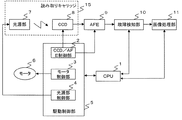
まず、本発明の実施形態に係る画像読取装置の構成について説明する。図3は、本実施形態に係る画像形成装置の機能ブロック図である。本実施形態に係る画像読取装置は、CPU(Central Processing Unit)1、駆動制御部5、モータ6、光源部7、CCD(Charge Coupled Device)8、AFE(Analog Front End)9、故障検知部10、画像処理部11から構成される。
<Configuration>
First, the configuration of the image reading apparatus according to the embodiment of the present invention will be described. FIG. 3 is a functional block diagram of the image forming apparatus according to the present embodiment. An image reading apparatus according to this embodiment includes a CPU (Central Processing Unit) 1, a
CPU1は、画像読取装置全体の制御を行う。 The CPU 1 controls the entire image reading apparatus.
駆動制御部5は、CCD/AFE制御部2、モータ制御部3、光源部制御部4を有するエレキモジュールである。CCD/AFE制御部2は、CCD及びAFEを駆動する為の制御信号を出力する機能を有する。モータ制御部3は、モータ6を駆動する為の制御信号を出力する機能を有する。LED制御部4は、LED7を駆動する為の制御信号を出力する機能を有する。各制御部はCPU1により制御され、その設定に基づき駆動信号を出力する。
The
モータ6は、読み取りキャリッジ15を駆動して原稿を走査するモータである。
The
読み取りキャリッジ15は、光源部7及びCCD8を含む。光源部7は、原稿照射用のスキャナ用光源であり、点光源であるLEDが主走査方向に複数個アレイ状に並べて構成され、線光源として採用している。CCD8は、撮像手段としての読み取りデバイスである。光源部7から照射された光が原稿に反射し、その反射光がレンズで集光されCCD8上で結像される。なお、図3に示す読み取りキャリッジ15の構成は概略であり、詳細は後述する。
The reading
AFE9は、CCD8から出力されたアナログ画像信号をデジタル画像データに変換して出力する。さらに、出力するデジタル画像データの暗オフセットレベル調整及び明出力調整機能を有しても良い。
The
故障検知部10は、後述するハレーション発生部24からの反射光がCCD8に入射され、AFE9にて変換されたデジタル画像データからLED故障を検出する。具体的には、光源部7に配置された複数のLEDの位置関係と、ハレーションにより出力レベルが局所的に高くなった画素位置の関係により、LED故障を検出する。すなわち、ハレーションを強制的に発生させると、出力レベルが局所的に高くなった画素位置が確認できるが、かかる出力レベルが、予め定めた規定値を超えていなかった場合は、その部分に対応する位置にあるLEDの発光が十分ではないということであり、すなわち故障していることが検出できる。
The
画像処理部10は、AFE9から出力されたデジタル画像データを画像処理する。例えば、暗出力補正、シェーディング補正、ガンマ補正などの処理を行う。
The
図4は、本実施形態に係る画像読取装置の概略断面図である。スキャナユニット16、ADF(Auto Document Feeder:自動原稿紙送り装置)12、原稿圧板13、原稿ガラス14、読み取りキャリッジ15、ADF用原稿ガラス23、ハレーション発生部24、基準白版25、から構成される。
FIG. 4 is a schematic cross-sectional view of the image reading apparatus according to the present embodiment. A
ここでは、原稿を原稿ガラス14に載置してキャリッジ15を移動させながら光を照射して読み取る原稿静止型と、ADF12に原稿を流してADF用原稿ガラス23上を通る原稿に光を照射して読み取るADF型と、の両機能を備えたスキャナユニット16を用いて説明する。本実施形態は、ハレーション発生部24を用いたLED故障検出が、原稿静止型とADF型のいずれにも対応出来ることを説明するための実施形態であり、原稿静止型若しくはADF型のいずれか一方の機能のみを少なくとも有する画像読取装置に本発明を適用することも当然可能である。
Here, the original is placed on the
スキャナユニット16は、原稿の読み取り(スキャンとも称す)を行う。図中、スキャン領域とスキャン方向を矢印で示す。
The
ADF12は、原稿有り無しを検出して自動的に原稿を搬送する。ADF12に搬送された原稿は、ADF原稿用ガラス23の上を通り、この時読み取りキャリッジ15によって読み取られる。
The ADF 12 automatically detects the presence / absence of a document and automatically conveys the document. The document conveyed to the ADF 12 passes through the
原稿圧板13は、原稿ガラス14にセットされた原稿を押さえるための圧板である。原稿ガラス14は、原稿を載置するためのガラスである。
The
読み取りキャリッジ15は、読み取りデバイスであるCCD8や光源部7などが実装されたモジュールである。
The reading
基準白版25は、各種補正用のデータとなる白レベル基準データを取得する際に利用される。
The reference
ハレーション発生部24は、光源部7からの光が原稿に照射されその際の正反射作用の影響で強い光強度のままCCD8へ入射してしまう時に顕著に現れる現象であるハレーションを強制的に発生させる。ハレーション発生部24の実施例について以下説明する。
The
(実施例1)
図10は、ハレーション発生部の構成の一例を示す概略断面図である。ハレーションは、光源部7からの光が原稿に照射されその際の正反射作用の影響で強い光強度のままCCD8へ入射してしまう時に顕著に現れる現象である。従って実施例1に係るハレーション発生部34は、副走査方向へ湾曲した物理形状とする。読み取りキャリッジ15でハレーション発生部34を走査することにより、副走査方向でのいずれかの場所で正反射光が光軸上に入射し、強制的にハレーションを発生させることが可能となる。ハレーション発生部34で使用する部材は、ハレーションをより顕著にさせるため、光沢のある黒い部材などにしても良い。
Example 1
FIG. 10 is a schematic cross-sectional view showing an example of the configuration of the halation generator. The halation is a phenomenon that appears prominently when the light from the
(実施例2)
図11は、ハレーション発生部の構成の一例を示す概略断面図である。実施例2に係るハレーション発生部44は、実施例1とは上下逆に湾曲している開口角の広い部材を想定したものである。開口角の広い部材とは、あらゆる角度からの光を集光可能な光学的特性を有するものなどが考えられる。車内に設置するバックミラーや、近年では道路の曲がり角などで衝突防止の為に設置されているミラーのような、FF(Fantastic Flat)ミラー等である。この様な光学的特性を有する部材の下を読み取りキャリッジ15で走査することにより、いずれかの場所で正反射光が光軸上に入射し、強制的にハレーションを発生させることが可能となる。
(Example 2)
FIG. 11 is a schematic cross-sectional view showing an example of the configuration of the halation generator. The
なお、本実施形態に係るハレーション発生部24の構成は上記実施例に限られることはなく、読み取りキャリッジ15でハレーション発生部24を走査した場合に、いずれかの場所で正反射光が光軸上に入射し、強制的にハレーションを発生させることを可能とする構成であれば良い。
Note that the configuration of the
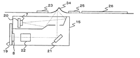
図5は、本実施形態に係る画像読取装置内の読み取りキャリッジ15と、ADFでの原稿読み取り位置であるADF用原稿ガラス23、ハレーション発生部24、基準白板25、フラットベットスキャン時の原稿読み取り位置である原稿ガラス14の位置関係を説明するための概略断面図である。ただし、図5に示す位置関係は一例であり、ハレーション発生部24は、読み取りキャリッジ15が通過し得る箇所に設けられていれば良い。なお、図5に示すように、少なくとも通常の画像読取対象物の読取りを行う際にも通過する箇所にハレーション発生部24設ければ、LEDの故障検知を行うことによる動作的時間的負担が解消され得る。
FIG. 5 shows a reading
読み取りキャリッジ15は、光源部基板20に実装された光源部7、ミラー21、レンズ22、SBU(Sensor Board Unit;読み取り用基板)19に実装されたCCD8、から構成される。読み取りキャリッジ15の移動は、モータ制御部3(図3参照)から出力されるパルス情報に基づきモータ6が駆動することにより移動する。
The reading
光源部基板20上にはLEDが主走査方向に複数個実装されている。LED駆動信号は光源部制御部4(図3参照)から光源部基板20に入力される。
A plurality of LEDs are mounted on the light
ミラー21は、光源部7から照射された光が原稿に反射し、その反射光を折り返す為のミラーである。図5では1枚しか記載していないが、実際には複数枚のミラーで構成される。
The
レンズ22は、原稿からの反射光を集光する為のレンズである。
The
CCD8は、SBU23上に実装される読み取りデバイスである。レンズ22で集光された原稿からの反射光がCCD上で結像される。
The
ADF用原稿ガラス23は、原稿をADFで搬送して読み取りを行う際のガラスである。ADFで読み取る際には、読み取りキャリッジ15をADF用原稿ガラス23の下部に移動させ、このガラス上を原稿が移動する事により読み取りを行う。なお、かかる原稿読み取りの前に、後述するハレーション発生部24の下部へ移動してLED故障検知を行い、さらに基準白版25下部へ移動して各種補正用のデータとなる白レベル基準データを取得する。
The ADF
ハレーション発生部24は、光源を点灯した状態でこの部分を読み取った場合、強制的にハレーションを発生する部分である。ハレーション発生部の具体的構成は後述する。
The
基準白板25は、白レベルの基準となる部材である。基準白板25を読み取ることによりAFEでの白レベル調整やシェーディング補正用のデータとして使用する。
The reference
原稿ガラス14は、フラットベット読み取り用のガラスである。原稿ガラス14上に原稿が置かれると読み取りキャリッジ15は原稿ガラス14下部に移動して原稿を走査する。なお、原稿ガラス14下部に移動する際に、ハレーション発生部24と基準白版25の下部を通る構成となるため、この際にLED故障検知や、各種補正用のデータとなる白レベル基準データを取得できる。
The
ADF用原稿ガラス23、ハレーション発生部24、基準白板25、原稿ガラス14を、図5に示した様な位置関係に置き、原稿読み取りの前にシェーディングデータを生成する為に基準白板へ移動する途中にハレーション発生部24を配置することで、読み取りの生産性を落とさずにLED故障検知を行うことが可能となる。
The ADF
<LED故障検知>
故障検知部10によるLED故障検知の詳細について説明する。まず、光源部7のLEDと読み取りデバイスであるCCD8の位置関係について説明する。図6は、画像読取装置の光学的位置関係図である。光源部基板20に実装された複数のLEDが発光し、レンズ22で集光されSBU23に実装されたCCD18に結像される。
<LED failure detection>
Details of LED failure detection by the
図7は、基準白板読み取り時のCCD出力1ライン分の出力分布を示す図である。すなわち、LEDが発光して基準白板25を照射した反射光がCCD8に入射し、CCD8から出力されるアナログ画像データをAFE9にてデジタルデータに変換した時の1ライン分の主走査方向での分布である。点光源であるLEDを複数個並べて、その光を読み取りキャリッジ15内部で光学的に拡散させた状態で原稿を照射するので、原稿面の1ラインでは、ほぼ均一な光が照射され、画像データの分布も均一になる。
FIG. 7 is a diagram showing an output distribution for one line of the CCD output at the time of reading the reference white plate. That is, the reflected light that is emitted from the LED and irradiates the reference
図8は、ハレーション発生部読み取り時、ハレーションが発生した際のCCD出力1ライン分の出力分布を示す図である。図7と同様に、すなわち、LEDが発光してハレーション発生部24を照射した反射光がCCD8に入射し、CCD8から出力されるアナログ画像データをAFE9にてデジタルデータに変換した時の1ライン分の主走査方向での分布である。ハレーション発生部24を走査した際、基準白板読み取り時の様に均一な光はCCD8に入射せず、複数個並んだLEDのピッチに相当する画素数の間隔置きに強い光が入射することになる。従ってCCD8から出力されるアナログ画像データは周期的に高い出力となる。ハレーション発生部24にて強制的にハレーションを発生させている為、この様な分布となる。
FIG. 8 is a diagram showing an output distribution for one line of CCD output when halation occurs when reading the halation generator. As in FIG. 7, that is, the reflected light that is emitted from the LED and irradiates the
読み取りキャリッジ15でハレーション発生部24を走査した際のAFE9から出力されたデジタルデータ(ハレーションデータと称す)を受け取った故障検知部10は、ハレーションデータにおけるLEDピッチに相当する位置のピーク値を、予め設定したスレッシュ(規定値)と比較し、LED故障の有無を検出する。すなわち、スレッシュレベルに満たない場合はLEDが故障していると判断出来る。
The
<動作処理>
図9は、本実施形態に係る画像読取装置におけるLED故障検知の動作処理を示すフローチャートである。
<Operation processing>
FIG. 9 is a flowchart showing an operation process of LED failure detection in the image reading apparatus according to the present embodiment.
スキャン起動が実行されると(ステップS1/Yes)、読み取りキャリッジ15がハレーション発生部24の下部へ移動する(ステップS2)。スキャン起動は、例えば画像読取装置に実装された操作部よりユーザがコピーを起動する、或いは読取装置外部の機器(例えばPC(Personal Computer))からスキャナ用途としてスキャンが実行されたことをCPU1が検出する。CPU1はモータ制御部3に制御信号を入力し、モータ制御部3はモータ6を駆動して読み取りキャリッジ15をハレーション発生部24の下部に移動させる。
When scan activation is executed (step S1 / Yes), the reading
読み取りキャリッジ15がハレーション発生部24に到達すると、LED実装位置に相当する1ライン中での画素位置の画像信号レベルをピークホールドする。これをハレーション発生部24の走査が終了するまで繰り返す(ステップS3〜S6)。ピークホールドする画素は、例えばLEDが実装された位置がCCD上の1000画素に相当する場合、その周辺画素(100画素など)の平均値を算出して、そのラインのピーク値とする事により突発的なノイズ成分などを除去する。
When the reading
ハレーション発生部24の走査が終了した後、故障検知部10は、各LED実装位置での画像信号レベルのピーク値が基準値以上であるか判断する(ステップS7、S8)。
After the scanning of the
規定値以下の場合(ステップS8/No)、LEDが点灯していない(LED故障検知)と判断して、操作部からのコピー起動の場合には、操作部上に警告の旨を表示する。外部機器からのスキャン実行の場合には、外部機器の表示部上に警告の旨を表示する。 If it is equal to or less than the specified value (step S8 / No), it is determined that the LED is not lit (LED failure detection), and a warning message is displayed on the operation unit when a copy is started from the operation unit. When scanning is performed from an external device, a warning message is displayed on the display unit of the external device.
規定値以上の場合には(ステップS8/Yes)、読み取りキャリッジ15を基準白板25の下部に移動させ(ステップS10)、シェーディング補正用のデータを取得後(ステップS11)、原稿ガラス上に置かれた原稿を走査することにより読み取り動作を完了する(ステップS12)。
If it is equal to or greater than the prescribed value (step S8 / Yes), the reading
上記動作処理の場合、故障検知部10でLED故障が検知されると、CPU1はモータ制御部3に制御信号を送り、読み取り動作を終了させることとなる。しかしながら、基準値以下(ステップS8/No)の場合でも、原稿を走査(ステップS10〜S12)した後に警告(ステップS9)を表示しても良い。
In the case of the above-described operation processing, when the
上記動作処理は、原稿がフラットベットガラス(原稿ガラス14)に置かれた場合でも、ADFに原稿がセットされた場合でも同様の処理となる。すなわち、フラットベットガラス(原稿ガラス14)に原稿が置かれ、スキャン動作が開始されると、先ずハレーション発生部24でのLED故障検知を行い、次に基準白板25に移動してシェーディング補正用データの生成を行う。更に原稿ガラス14下部に移動して原稿読み取りを行う。図4において矢印で示すスキャン方向に読み取りキャリッジが1度移動することで、読み取り動作に伴ってLED故障検知動作を行うことが出来る。
The above operation process is the same whether the original is placed on the flat bed glass (original glass 14) or the original is set on the ADF. That is, when an original is placed on the flat bed glass (original glass 14) and a scanning operation is started, LED failure is first detected by the
一方、ADFに原稿がセットされてスキャン動作が開始されると、先ずハレーション発生部24でのLED故障検知を行い、次に基準白板25に移動してシェーディング補正用データの生成を行ってからADF用原稿ガラス23下部に戻り原稿読み取り動作を行う。ADFに原稿をセットして読み取り動作を行う場合は、少なくとも基準白板25への移動は行うため、基準白板25とADF用原稿ガラス23との間にハレーション発生部24を設けることで、読み取り動作に伴ってLED故障検知動作を行うことが出来る。
On the other hand, when the document is set on the ADF and the scanning operation is started, the LED failure is first detected by the
上記実施形態により、本来はLED光源を使用する際のデメリットであるハレーション現象を利用して、強制的にハレーションを発生させる機構を設け、原稿読み取り動作の過程でハレーション発生部を走査することでハレーションデータを取得し、ハレーションデータからLED故障を検知することで、全てのLED光源を全点灯した状態でも、原稿読み取りと共にLED故障検知をすることが出来る。また、読み取り動作の度に故障検知が出来る。ユーザは任意のタイミングで操作部等から読み取り動作を起動させ、故障検知が出来る。 According to the above-described embodiment, a mechanism for forcibly generating halation is provided by utilizing the halation phenomenon, which is a disadvantage when using an LED light source, and the halation is generated by scanning the halation generation unit in the course of the document reading operation. By acquiring the data and detecting the LED failure from the halation data, it is possible to detect the LED failure while reading the document even when all the LED light sources are turned on. In addition, failure can be detected at every reading operation. The user can start a reading operation from an operation unit or the like at an arbitrary timing to detect a failure.
なお、図9のフローチャートに示す処理を、CPU1が実行するためのプログラムは本発明によるプログラムを構成する。このプログラムを記録する記録媒体としては、半導体記憶部や光学的及び/又は磁気的な記憶部等を用いることができる。このようなプログラム及び記録媒体を、前述した各実施形態とは異なる構成のシステム等で用い、そこのCPUで上記プログラムを実行させることにより、本発明と実質的に同じ効果を得ることができる。 The program for the CPU 1 to execute the processing shown in the flowchart of FIG. 9 constitutes a program according to the present invention. As a recording medium for recording the program, a semiconductor storage unit, an optical and / or magnetic storage unit, or the like can be used. By using such a program and a recording medium in a system having a configuration different from that of each of the above-described embodiments and causing the CPU to execute the program, substantially the same effect as the present invention can be obtained.
以上、本発明を好適な実施形態に基づき具体的に説明したが、本発明は上記のものに限定されるものではなく、その要旨を逸脱しない範囲で種々変更可能であることは言うまでもない。 Although the present invention has been specifically described above based on the preferred embodiments, it is needless to say that the present invention is not limited to the above-described ones and can be variously modified without departing from the gist thereof.
1 CPU
2 CCD/AFE
3 モータ制御部
4 光源部制御部
5 駆動制御部
6 モータ
7 光源部
8 CCD
9 AFE
10 故障検知部
11 画像処理部
12 ADF
13 原稿圧板
14 原稿ガラス
15 読み取りキャリッジ
16 スキャナユニット
19 SBU
23 ADF用原稿ガラス
24、34、44 ハレーション発生部
25 基準白版
30 平面原稿
31 立体原稿
1 CPU
2 CCD / AFE
3
9 AFE
10
13
23 ADF
Claims (11)
前記光源部から照射された光が反射した際にハレーションを生じさせる構造の被読取面を設けたハレーション発生手段と、
前記光源部から照射された光が前記ハレーション発生手段に設けられた被読取面に反射した反射光を電荷に変え電気信号として前記撮像手段から出力されたデータであるハレーションデータのうち、画像信号レベルが予め定めた規定値に満たない箇所があるか否か判断することで、前記発光素子の故障を検知する故障検知手段と、
を備えることを特徴とする画像読取装置。 A light source unit in which a plurality of light emitting elements are arranged in one or a plurality of columns, and an imaging unit that images the image reading object based on reflected light reflected by the image reading object by light emitted from the light source unit; An image reading apparatus comprising:
A halation generating means provided with a read surface having a structure for generating halation when the light emitted from the light source part is reflected;
The image signal level of the halation data, which is data output from the imaging unit as an electric signal, is converted from the reflected light reflected from the read surface provided in the halation generation unit to the light irradiated from the light source unit. Is a failure detection means for detecting a failure of the light emitting element by determining whether or not there is a location that does not meet a predetermined specified value;
An image reading apparatus comprising:
前記光源部は、前記キャリッジに備えられていることを特徴とする請求項1から7のいずれか1項記載の画像読取装置。 The halation generation means is provided at a location where a carriage passes when imaging the image reading object .
The image reading apparatus according to claim 1 , wherein the light source unit is provided in the carriage .
前記光源部から光を照射するステップと、
前記光源部から照射された光が反射した際にハレーションを生じさせる構造の被読取面を設けたハレーション発生部に照射され、前記ハレーション発生手段に設けられた被読取面に反射した反射光を電荷に変え電気信号として前記撮像手段からデータを出力するステップと、
前記ハレーション発生手段に設けられた被読取面に反射した反射光を電荷に変え電気信号として前記撮像手段から出力されたデータであるハレーションデータのうち、画像信号レベルが予め定めた規定値に満たない箇所があるか否か判断することで、前記発光素子の故障を検知するステップと、
を備えることを特徴とする故障検知方法。 A light source unit in which a plurality of light emitting elements are arranged in one or a plurality of columns, and an imaging unit that images the image reading object based on reflected light reflected by the image reading object by light emitted from the light source unit; A failure detection method in an image reading apparatus comprising:
Irradiating light from the light source unit;
Charge the reflected light reflected on the read surface provided on the read surface provided on the halation generating means, and provided on the read surface provided with the structure to generate halation when the light emitted from the light source is reflected. Instead of outputting data from the imaging means as an electrical signal;
Of the halation data, which is data output from the imaging means as an electric signal, by changing the reflected light reflected on the surface to be read provided in the halation generating means into electric charges, the image signal level does not reach a predetermined specified value. Determining whether there is a location, detecting a failure of the light emitting element;
A failure detection method comprising:
前記光源部から光を照射する処理と、
前記光源部から照射された光が反射した際にハレーションを生じさせる構造の被読取面を設けたハレーション発生部に照射され、前記ハレーション発生手段に設けられた被読取面に反射した反射光を電荷に変え電気信号として前記撮像手段からデータを出力する処理と、
前記ハレーション発生手段に設けられた被読取面に反射した反射光を電荷に変え電気信号として前記撮像手段から出力されたデータであるハレーションデータのうち、画像信号レベルが予め定めた規定値に満たない箇所があるか否か判断することで、前記発光素子の故障を検知する処理と、
をコンピュータに実行させることを特徴とする故障検知プログラム。 A light source unit in which a plurality of light emitting elements are arranged in one or a plurality of columns, and an imaging unit that images the image reading object based on reflected light reflected by the image reading object by light emitted from the light source unit; A failure detection program in an image reading apparatus comprising:
A process of irradiating light from the light source unit;
Charge the reflected light reflected on the read surface provided on the read surface provided on the halation generating means, and provided on the read surface provided with the structure to generate halation when the light emitted from the light source is reflected. Processing to output data from the imaging means as an electrical signal instead of,
Of the halation data, which is data output from the imaging means as an electric signal, by changing the reflected light reflected on the surface to be read provided in the halation generating means into electric charges, the image signal level does not reach a predetermined specified value. By determining whether there is a place, processing to detect a failure of the light emitting element,
A failure detection program for causing a computer to execute.
Priority Applications (1)
| Application Number | Priority Date | Filing Date | Title |
|---|---|---|---|
| JP2009030127A JP5212157B2 (en) | 2009-02-12 | 2009-02-12 | Image reading apparatus, failure detection method, program, and recording medium |
Applications Claiming Priority (1)
| Application Number | Priority Date | Filing Date | Title |
|---|---|---|---|
| JP2009030127A JP5212157B2 (en) | 2009-02-12 | 2009-02-12 | Image reading apparatus, failure detection method, program, and recording medium |
Publications (2)
| Publication Number | Publication Date |
|---|---|
| JP2010187221A JP2010187221A (en) | 2010-08-26 |
| JP5212157B2 true JP5212157B2 (en) | 2013-06-19 |
Family
ID=42767596
Family Applications (1)
| Application Number | Title | Priority Date | Filing Date |
|---|---|---|---|
| JP2009030127A Expired - Fee Related JP5212157B2 (en) | 2009-02-12 | 2009-02-12 | Image reading apparatus, failure detection method, program, and recording medium |
Country Status (1)
| Country | Link |
|---|---|
| JP (1) | JP5212157B2 (en) |
Families Citing this family (3)
| Publication number | Priority date | Publication date | Assignee | Title |
|---|---|---|---|---|
| JP5624945B2 (en) * | 2011-05-31 | 2014-11-12 | 京セラドキュメントソリューションズ株式会社 | Image reading apparatus and image forming apparatus |
| JP2014236328A (en) | 2013-05-31 | 2014-12-15 | 京セラドキュメントソリューションズ株式会社 | Image reading device, image forming device, and computer program |
| JP6479625B2 (en) | 2015-10-13 | 2019-03-06 | 株式会社ジャパンディスプレイ | Display device with touch detection function |
Family Cites Families (6)
| Publication number | Priority date | Publication date | Assignee | Title |
|---|---|---|---|---|
| JP2522433Y2 (en) * | 1988-11-11 | 1997-01-16 | 三田工業株式会社 | Light source abnormality detection device for document illuminator |
| JP3715952B2 (en) * | 2002-07-05 | 2005-11-16 | キヤノン株式会社 | Image reading device |
| JP2004064406A (en) * | 2002-07-29 | 2004-02-26 | Canon Inc | Image reading device and its control program |
| JP4989903B2 (en) * | 2006-02-13 | 2012-08-01 | 株式会社リコー | LIGHTING DEVICE, IMAGE READING DEVICE, AND IMAGE FORMING DEVICE |
| JP2008124891A (en) * | 2006-11-14 | 2008-05-29 | Ricoh Co Ltd | Image reading apparatus and image forming apparatus |
| JP2009010830A (en) * | 2007-06-29 | 2009-01-15 | Ricoh Co Ltd | Image reader, and image forming device |
-
2009
- 2009-02-12 JP JP2009030127A patent/JP5212157B2/en not_active Expired - Fee Related
Also Published As
| Publication number | Publication date |
|---|---|
| JP2010187221A (en) | 2010-08-26 |
Similar Documents
| Publication | Publication Date | Title |
|---|---|---|
| JPH09139812A (en) | Document scanner | |
| JP2007318744A (en) | Image reading apparatus and document detecting method | |
| JP5212157B2 (en) | Image reading apparatus, failure detection method, program, and recording medium | |
| JP2010166562A (en) | Shading correction apparatus, image scanning apparatus, and method of setting adopted areas of shading correction apparatus | |
| US7961361B2 (en) | Image reading apparatus, image reading method and image reading program | |
| JP5267239B2 (en) | Image reading apparatus, image reading method, image reading program, and recording medium | |
| US7224483B2 (en) | Image signal correction light source that can cope with dust and scratch on transparent document, and its control | |
| US20140063561A1 (en) | Image processing apparatus, image forming apparatus, and image processing method | |
| JP2004126284A (en) | Image read unit and image reader | |
| JP2014230117A (en) | Document reader and document reading method | |
| JP2003037713A (en) | Image reader | |
| JP5423267B2 (en) | Image reading apparatus, image reading method, program, and recording medium | |
| US6532084B1 (en) | Method for detecting the relative location of an image reading head and a light source | |
| JP2011087109A (en) | Abnormal image detecting apparatus, image forming apparatus, abnormal image detecting method, image forming method, and program | |
| JP2010219965A (en) | Image reader, and image forming apparatus including the same | |
| JPH09200445A (en) | Image reader | |
| JP5493665B2 (en) | Image reading apparatus and image reading method | |
| JP2018207138A (en) | Scanner and method for producing scan data | |
| JP2006246137A (en) | Image-reading apparatus | |
| RU2154916C2 (en) | Method and device for image data scanning in image processing system | |
| JP2011029709A (en) | Reader, image forming device, reading control method, image forming method, program, and recording medium | |
| JP2011120182A (en) | Image reading apparatus | |
| JP5970413B2 (en) | Image reading device | |
| JP2003333335A (en) | Image processing apparatus | |
| JP2009188750A (en) | Document reading apparatus |
Legal Events
| Date | Code | Title | Description |
|---|---|---|---|
| A621 | Written request for application examination |
Free format text: JAPANESE INTERMEDIATE CODE: A621 Effective date: 20120126 |
|
| A521 | Written amendment |
Free format text: JAPANESE INTERMEDIATE CODE: A523 Effective date: 20120618 |
|
| A977 | Report on retrieval |
Free format text: JAPANESE INTERMEDIATE CODE: A971007 Effective date: 20121026 |
|
| A131 | Notification of reasons for refusal |
Free format text: JAPANESE INTERMEDIATE CODE: A131 Effective date: 20121113 |
|
| A521 | Written amendment |
Free format text: JAPANESE INTERMEDIATE CODE: A523 Effective date: 20130109 |
|
| TRDD | Decision of grant or rejection written | ||
| A01 | Written decision to grant a patent or to grant a registration (utility model) |
Free format text: JAPANESE INTERMEDIATE CODE: A01 Effective date: 20130129 |
|
| A61 | First payment of annual fees (during grant procedure) |
Free format text: JAPANESE INTERMEDIATE CODE: A61 Effective date: 20130211 |
|
| FPAY | Renewal fee payment (event date is renewal date of database) |
Free format text: PAYMENT UNTIL: 20160308 Year of fee payment: 3 |
|
| LAPS | Cancellation because of no payment of annual fees |