JP5208643B2 - Stationary processing equipment - Google Patents
Stationary processing equipment Download PDFInfo
- Publication number
- JP5208643B2 JP5208643B2 JP2008245910A JP2008245910A JP5208643B2 JP 5208643 B2 JP5208643 B2 JP 5208643B2 JP 2008245910 A JP2008245910 A JP 2008245910A JP 2008245910 A JP2008245910 A JP 2008245910A JP 5208643 B2 JP5208643 B2 JP 5208643B2
- Authority
- JP
- Japan
- Prior art keywords
- shaft
- attachment
- transmission
- double
- cutting
- Prior art date
- Legal status (The legal status is an assumption and is not a legal conclusion. Google has not performed a legal analysis and makes no representation as to the accuracy of the status listed.)
- Active
Links
Images


Landscapes
- Drilling And Boring (AREA)
Description
本発明は、大型の構造物、例えば、大型船舶のプロペラや、大型タービン発電機のステータのボス加工に用いられる据えぐり加工装置に関する。 The present invention relates to an upsetting apparatus used for boss processing of a large structure, for example, a propeller of a large ship or a stator of a large turbine generator.
大型船舶のプロペラや、発電所に設置される発電機のステータなどは、大きなものになると高さが10メートルを超えるものがある。このような大型構造物の加工は、大型のマシニングセンタといえども不可能である。 Large propellers for generators and stators for generators installed at power plants are larger than 10 meters in height. Processing such a large structure is impossible even for a large machining center.
そこで、従来は、特殊な加工装置を大型構造物の中に設置して加工を行っていた。
例えば、特許文献1では、大型構造物の内部を旋削加工する加工装置が提案されている。この加工装置は、旋回コラムと、旋回駆動部を大型構造物の内部に設置し、この旋回コラムに加工ヘッドを取り付けたものある。この加工ヘッドは、旋回コラムを昇降する移動機構と、内径部の半径方向に移動する移動機構を備えている。
Therefore, conventionally, a special processing apparatus is installed in a large structure for processing.
For example, Patent Document 1 proposes a machining apparatus that performs turning inside a large structure. In this machining apparatus, a swiveling column and a swivel drive are installed inside a large structure, and a machining head is attached to the swiveling column. The machining head includes a moving mechanism that moves the swivel column up and down and a moving mechanism that moves in the radial direction of the inner diameter portion.
大型構造物の内周部を旋削するときには、旋回コラムを旋回させ、加工ヘッドを昇降させながら旋回ヘッドに装着した工具で大型工具の内周部を旋削する。また、この加工装置では、加工ヘッドにアタッチメントを取り付け、アタッチメントに装着したドリルやエンドミルで穴あけ加工をすることもできるようになっている。
しかしながら、大型構造物を加工する従来技術では、以下のような問題点がある。 However, the conventional technique for processing a large structure has the following problems.
まず、内周面を旋削するには、ボーリングアタッチメントを用い、端面を旋削する加工にはフェーシングアタッチメントを用いるというように、異なる種類の加工を行うためには、アタッチメントを交換することが必須となる。 First, in order to perform different types of processing, such as using a boring attachment for turning the inner peripheral surface and using a facing attachment for turning the end surface, it is essential to replace the attachment. .
しかし、従来のこの種の加工機は、余りにも大きな構造物を対象とする特殊な加工機であるため、マシニングセンタなどの汎用的な工作機械とは違って自動化が進んでおらず、現状では、作業員が段取り作業台に乗ってボルトを締め付けたり、外したりしてアタッチメントのクランプ、アンクランプといった操作を手動で行なわなければならないので、効率が悪く、アタッチメント交換作業に長時間を要していた。 However, since this type of conventional processing machine is a special processing machine that targets too large structures, unlike general-purpose machine tools such as machining centers, automation has not progressed. Since the operator had to manually perform operations such as clamping and unclamping the attachment by tightening or removing the bolts on the setup work table, it was inefficient and it took a long time to replace the attachment. .
また、大型構造物の内径部の中心と、加工機の旋回中心との芯出しを行うことが必要となるが、従来は、加工機を据え付けるときに、その据え付け作業の一環として、芯出し作業を行っていた。しかし、設置した後は、芯出しを修正することが困難であった。 In addition, centering the center of the inner diameter of a large structure and the turning center of the processing machine is required. Conventionally, when the processing machine is installed, the centering work is performed as part of the installation work. Had gone. However, after installation, it was difficult to correct the centering.
さらに、従来の加工機では、アタッチメントを上下に送る軸はNC化されていたが、工具を切り込ませる軸は、NC化されておらず、手動で行っているのが現状である。この点、特許文献1の加工機では、加工用ヘッドを上下に送る軸と、工具を切込む軸の2軸をもっているが、これらの軸を駆動するモータは加工ヘッド側に設けられている。加工用ヘッドは、旋回コラムとともに旋回するため、加工用ヘッドへの電力供給と制御信号の授受は、旋回コラムに設けたスリップリングを介して行っている。このスリップリングには摩擦などにより消耗が生じるので、メンテナンスを十分に行わないと故障することが多かった。 Furthermore, in the conventional processing machine, the axis for feeding the attachment up and down is NC, but the axis for cutting the tool is not NC and is currently being performed manually. In this regard, the processing machine of Patent Document 1 has two axes, a shaft for feeding the processing head up and down and a shaft for cutting the tool, and a motor for driving these shafts is provided on the processing head side. Since the machining head swivels together with the swiveling column, power supply to the machining head and transmission / reception of control signals are performed via a slip ring provided on the swiveling column. Since this slip ring is consumed due to friction or the like, it often breaks down if it is not sufficiently maintained.
そこで、本発明の目的は、前記従来技術の有する問題点を解消し、アタッチメントのクランプ機構を自動化し、また、切込軸と送り軸の2軸の駆動を、固定された主軸台の方から中空2重の伝動機構により伝動することにより、2軸とも信頼性高いNC化を達成でき、さらに、主軸台の位置を同時2軸制御できるようにすることにより正確な心出しを自動化できるようにした据えぐり加工装置を提供することにある。 Therefore, an object of the present invention is to eliminate the problems of the prior art, to automate the attachment clamping mechanism, and to drive the two axes of the cutting shaft and the feed shaft from the fixed headstock direction. By transmitting with a hollow double transmission mechanism, it is possible to achieve highly reliable NC for both axes, and to enable accurate centering by enabling simultaneous control of the position of the headstock by two axes. It is in providing a stationary processing apparatus.
前記の目的を達成するために、本発明は、大型構造物をワークとして定盤に固定した前記ワークに穴加工および端面加工を行う据えぐり加工装置であって、工具の送り軸と、工具をワークに切り込ませる切込軸と、前記送り軸と切込軸にそれぞれ動力を伝動する平行伝動軸と、を有するアタッチメントと、前記アタッチメントが取り付けられる主軸を有する主軸台と、前記主軸台に配置され、前記主軸を駆動するサーボモータを有する主軸回転駆動機構と、前記主軸台に配置され、前記アタッチメントの切込軸駆動用サーボモータを有する切込軸駆動機構と、前記主軸台に配置され、前記アタッチメントの送り軸駆動用サーボモータを有する送り軸駆動機構と、前記主軸の中心部に回転自在に支持される内側伝動軸と、前記内側伝動軸を同軸に回転自在に収容する中空伝動軸とからなる、前記切込軸駆動機構および前記送り軸駆動機構に接続される二重伝動軸と、前記二重伝動軸と前記アタッチメント間で伝動接続をするクラッチと、前記アタッチメントに設けられ、前記二重伝動軸の同軸2軸伝動から平行2軸伝動に伝動形式を変換して前記送り軸、切込軸にそれぞれ伝動する伝動連結機構と、を備えたことを特徴とするものである。 In order to achieve the above object, the present invention provides an upsetting apparatus that performs hole machining and end face machining on a work that is fixed on a surface plate as a large structure, and includes a tool feed shaft and a tool. An attachment having a cutting shaft to be cut into the workpiece, a parallel transmission shaft that transmits power to the feed shaft and the cutting shaft, respectively, a headstock having a main shaft to which the attachment is attached, and disposed on the main shaft A spindle rotation driving mechanism having a servo motor for driving the spindle, and a cutting shaft driving mechanism having a servo motor for driving the cutting axis of the attachment, arranged on the spindle base, and arranged on the spindle base, A feed shaft drive mechanism having a servo motor for driving the feed shaft of the attachment, an inner transmission shaft rotatably supported at the center of the main shaft, and the inner transmission shaft coaxially A double transmission shaft connected to the cutting shaft drive mechanism and the feed shaft drive mechanism, and a clutch for transmission connection between the double transmission shaft and the attachment, comprising a hollow transmission shaft rotatably accommodated A transmission coupling mechanism that is provided in the attachment and converts a transmission type from a coaxial two-axis transmission of the double transmission shaft to a parallel two-axis transmission to transmit to the feed shaft and the cut shaft, respectively. It is a feature.
本発明では、前記アタッチメントは、前記ワークの内径部の旋削加工を行うためのボーリングアタッチメントであり、前記伝動連結機構は、前記二重伝動軸とクラッチを介して断続する二重中継ぎ軸と、前記工具をアタッチメントの軸方向に移動させる送り軸、前記工具をアタッチメントの半径方向に移動させる切込軸に伝動する平行な伝動軸に前記二重中継ぎ軸を接続する自在継手と、からなることを特徴とする。 In the present invention, the attachment is a boring attachment for turning the inner diameter portion of the workpiece, and the transmission coupling mechanism includes a double relay shaft that is intermittently connected via the double transmission shaft and a clutch, A feed shaft that moves the tool in the axial direction of the attachment, and a universal joint that connects the double joint shaft to a parallel transmission shaft that transmits the cutting shaft that moves the tool in the radial direction of the attachment. And
また、本発明では、前記アタッチメントは、アタッチメント本体の上端部から直角に延びるアーム部を有し、前記ワークの端面旋削加工を行うためのフェーシングアタッチメントであり、前記伝動連結機構は、前記二重伝動軸とクラッチを介して断続し前記アタッチメント本体内に延びる二重中継ぎ軸と、前記アーム部内部に設けられ前記工具の送り軸、切込軸に伝動する平行な伝動軸に前記二重中継ぎ軸を接続する歯車伝動機構と、からなることを特徴とする。 Further, in the present invention, the attachment is a facing attachment for performing an end face turning of the workpiece, the arm portion extending at a right angle from an upper end portion of the attachment main body, and the transmission coupling mechanism is the double transmission A double joint shaft that is intermittently connected via a shaft and a clutch and extends into the attachment main body, and a parallel transmission shaft that is provided inside the arm portion and is transmitted to the feed shaft and the cutting shaft of the tool. And a gear transmission mechanism to be connected.
本発明によれば、アタッチメントのクランプ機構を自動化し、また、切込軸と送り軸の2軸の駆動を、固定された主軸台の方から中空2重の伝動機構により伝動することにより、2軸とも信頼性高いNC化を達成でき、さらに、主軸台の位置を同時2軸制御できるようにすることにより正確な心出しを簡単に行うことができる。 According to the present invention, the attachment clamping mechanism is automated, and the drive of the two axes of the cutting shaft and the feed shaft is transmitted from the fixed headstock by the hollow double transmission mechanism. Accurate centering can be easily performed by making it possible to achieve highly reliable NC for both shafts, and by allowing the position of the headstock to be controlled simultaneously by two axes.
以下、本発明による据えぐり加工装置の一実施形態について、添付の図面を参照しながら説明する。
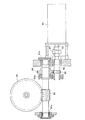
図1は、本発明一実施形態による据えぐり加工装置を示す断面図である。図2は、図1の据えぐり加工装置を上から見た平面図である。図1、図2において、参照番号10は、加工対象であるワークを示す。この実施形態では、大型構造物のワーク10として、大型船舶用のプロペラを例に挙げて、プロペラのボス部12の内周面とボス部12の端面を加工する。
Hereinafter, an embodiment of an upsetting apparatus according to the present invention will be described with reference to the accompanying drawings.
FIG. 1 is a cross-sectional view showing an upsetting apparatus according to an embodiment of the present invention. FIG. 2 is a plan view of the stationary processing apparatus of FIG. 1 as viewed from above. 1 and 2,
床面11には、加工装置の本体を収容するためのピット14が設けられている。定盤15は、ピット14を横断するように床面11に設置されている。ワーク10は、ブロック16を介して定盤15に据え付けられており、ブロック16によってボス部12が底上げされてワーク10のプロペラは定盤15に接触しないようになっている。
The
そこで、まず、据えぐり加工装置の構成について概要を説明する。
本実施形態による据えぐり加工装置は、ピット14に収容されている加工装置本体18と、アタッチメント20とに大きく分けられる。
First, an outline of the configuration of the upsetting apparatus will be described.
The stationary machining apparatus according to the present embodiment is roughly divided into a machining apparatus
据えぐり加工装置の本体18は、ベッド21と、このベッド21の上に設置されるサドル22と、このサドル22の上に設置される主軸台23と、から構成されている。サドル22は、ベッド21の上を前後方向(X軸方向)に移動し、主軸台23は、サドル22の上を左右方向(Y軸方向)に移動できるようになっている。主軸台23は、アタッチメント20を回転させる主軸24を有しており、アタッチメント20は、後述するアタッチメントクランプ装置によって、着脱可能に主軸24に固定されている。なお、図1に示すアタッチメント20は、ワーク10のボス部12の内周面を旋削するのに用いるボーリングアタッチメントである(以下、単にアタッチメント20と記載し、特に、ボーリングアタッチメントであることを明示するときは、ボーリングアタッチメント20と記載する。)。
The
以下、本実施形態による据えぐり加工装置の各部について詳細に説明する。
ベッド21は、ピット14の底面にレベリングブロック26を介して固定されている。ベッド21上面の左右両側には、サドル22を案内するガイドレール27が取り付けられている。サドル22を移動させる送り軸機構を駆動するのが、図2に示されるように、X軸サーボモータ28である。主軸台23は、サドル22に設けられたガイドレール29に案内される。この主軸台23を移動する送り軸機構は、Y軸サーボモータ30によって駆動される。この実施形態の据えぐり加工装置では、主軸台23は、X軸およびY軸の同時2軸数値制御により、水平面上の任意位置を正確に位置決めすることができるようになっている。
Hereinafter, each part of the upsetting apparatus according to the present embodiment will be described in detail.
The
次に、図3は、主軸台23の構成を示す断面図である。この図3において、参照番号32は、主軸台本体を示す。この主軸台本体32の内部は空洞になっている。主軸台本体32の上部には、主軸支持部33が一体に形成されている。主軸24は、主軸支持部33において、主軸ベアリング36によって回転自在に支持されている。
Next, FIG. 3 is a cross-sectional view showing the configuration of the
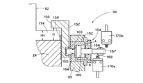
主軸24には、アタッチメントクランプ装置38によってアタッチメント20が着脱可能に固定される。アタッチメントクランプ装置38は、ノーズナット152と、ノーズナット152を回転しないようにする回り止め装置154とから構成されている。
The
ここで、アタッチメント20は、主軸24と一体で回転するが、ワーク10のボス部12を加工するには、工具82を送る必要がある。しかも、2方向、すなわち、軸方向と半径方向に工具82を送る必要がある。本実施形態の据えぐり加工装置では、主軸台23に動力源のサーボモータを配置しているため、動力をアタッチメント20に伝動する系統が2系統設けられることになる。なお、アタッチメント20がボーリングアタッチメントの場合は、軸方向送りが送り軸になり、半径方向送りが切込軸になる。以下の説明では、アタッチメント20がボーリングアタッチメントである場合について説明する。
Here, the
そこで、図3に示すように、主軸24の中心部には、内側伝動軸42と、中空伝動軸44とからなる二重伝動軸が設けられている。伝動軸が2重構造になっているのは、内側伝動軸42と中空伝動軸44のそれぞれが主軸台23に設けられている2系統のサーボモータ46、48の回転をアタッチメント20に伝動する伝動軸を構成しているからである。一つの系統は、内側伝動軸42に第1サーボモータ46の回転を伝え、噛み合いクラッチ、自在継手を介してアタッチメント20の切込軸に伝動する系統である。もう一つの系統は、第2サーボモータ48の回転を中空伝動軸44に伝え、噛み合いクラッチ、自在継手を介してアタッチメント20の送り軸に伝動する系統である。
Therefore, as shown in FIG. 3, a double transmission shaft including an
以下、主軸24、アタッチメント20のそれぞれの駆動伝動系統について順に説明する。
Hereinafter, the respective drive transmission systems of the
図4は、主軸台23に設けられている主軸24の回転駆動機構を示す。図3並びに図4において、主軸24の下端面には、ウォームホイール60が同軸にボルトによって固定されている。このウォームホイール60には、軸受61a乃至61cによって支持されたウォーム62が噛み合うようになっている。主軸駆動用サーボモータ64の出力軸65は、歯車軸66とカップリング67を介して連結されている。歯車軸66には、平歯車68が一体的に形成されている。ウォーム62の一端には、図示しないキーにより回り止めされて平歯車69が取り付けられ、この平歯車69に平歯車68が噛み合っている。
次に、図3には、アタッチメント20に伝動する2系統の駆動伝動機構が示されている。
FIG. 4 shows a rotational drive mechanism of the
Next, FIG. 3 shows two systems of drive transmission mechanisms that transmit to the
まず、第1サーボモータ46の回転は、次のようにして、二重伝動軸の内側伝動軸42に伝動される。伝動軸B1、B2はそれぞれ軸受によって平行に支持されており、伝動軸B1の一端が第1サーボモータ46に接続されている。伝動軸B1の他端には、平歯車70が取り付けられている。この平歯車70は、伝動軸B2に取り付けられている平歯車71と噛み合っている。そして、伝動軸B2の先端には、傘歯車72が取り付けられ、この傘歯車72は、内側伝動軸42の下端に取り付けられた傘歯車73と噛み合うようになっている。これら平歯車70、71、傘歯車72、73はいずれもそれが取り付けられている各伝動軸とは図示しないキーにより回り止めされている。
First, the rotation of the
同様に、第2サーボモータ48の回転は、次のようにして、二重伝動軸の中空回転軸44に伝動される。伝動軸C1、C2、C3がそれぞれ軸受によって平行に支持されており、伝動軸C1の一端が第2サーボモータ48に接続されている。伝動軸C1には、平歯車74が取り付けられ、この平歯車74は、伝動軸C2に取り付けられている平歯車75と噛み合っている。そして、伝動軸C2には、平歯車76が取り付けられ、この平歯車76は伝動軸C3に取り付けられた平歯車77に噛み合っている。伝動軸C3の先端には、傘歯車78が設けられ、この傘歯車78は、中空回転軸44の下端に取り付けられた傘歯車79噛み合うようになっている。これら平歯車74、75、76、77、傘歯車78、79はいずれもそれが取り付けられている各伝動軸とは図示しないキーにより回り止めされている。
Similarly, the rotation of the
次に、図5は、アタッチメント20に設けられている送り軸、切込軸からなる工具送り機構を示し、図6は、図5におけるVI−VI断面を示す。
図5、図6において、参照番号80は、アタッチメント20の本体を示す。このアタッチメント本体80は長円筒体で、主軸24に取り付けた状態では、図1に示されるように、ワーク10のボス部12を下から貫通して、さらに上に突き出るだけの高さを有しているので、ボス部12の全域および端面を加工することができる。また、アタッチメント本体80の外径は、ボス部の穴12aの内径よりも小さくなっている。
Next, FIG. 5 shows a tool feed mechanism including a feed shaft and a cutting shaft provided in the
5 and 6,
図5に示されるように、アタッチメント本体80の内部には、通路83が軸方向に形成されており、この通路83を工具82が取り付けられている移動ブロック84が移動する。この通路83には、切込軸を構成するスプライン軸85と、送り軸を構成するボールねじ軸86とが平行に配置されている。スプライン軸85の下端部にはベアリング支持85bとボス部85cとがスプライン軸85と一体に形成され、ボス部85cはボルトで自在継手128に連結されている。同様にボールねじ軸86の下端部には、ベアリング支持部86bとボス部86cとがボールねじ軸86と一体に形成され、ボス部86cは自在継手138に連結されている。
As shown in FIG. 5, a
アタッチメント20における送り軸の構成を先に説明する。移動ブロック84には、それぞれスプライン軸85、ボールねじ軸86が遊嵌する穴91、92が形成されている。このうち穴92の上部開口には、ボールナット93が固着されている。このボールナット93は、ボールねじ軸86に螺合している。したがって、本実施形態の送り軸機構によれば、ボールねじ軸86の回転は、ボールナット93によって移動ブロック84の軸方向の直線運動に転換されるので、移動ブロック84とともに工具82を軸方向に送ることができる。なお、図5のVI−VI断面を表す図6に示されるように、移動ブロック84の軸方向の直線運動を案内する2本のガイド97がアタッチメント本体80に固定されている。移動ブロック84には、ガイド97の三面からなる案内面をそれぞれ滑動する滑り板98a乃至98cが取り付けられている。参照番号99は、滑り板98aを保持する滑り板保持部材を示している。
The structure of the feed shaft in the
次に、図5、図6を参照してアタッチメント20における切込軸の構成について説明する。
まず、図6において、切込軸による工具82の移動方向は、アタッチメント本体80の半径方向である。移動ブロック84において、工具82は半径方向に向くように工具ホルダ100によって保持されている。工具84は、止めねじ101を用いて工具ホルダ100に固定されている。工具ホルダ100は、移動ブロック84において半径方向に延びる穴102に挿入されている。工具ホルダ100にはキー103が係合していて、このキー103によって回転が規制されているので、工具ホルダ100は回転はできないが、穴102を案内にして出入りする進退運動は許容されている。この工具ホルダ100を出入りさせるのは、次のようなウォーム歯車と、工具ホルダ100に形成したねじを組み合わせた機構である。
Next, the configuration of the cutting shaft in the
First, in FIG. 6, the moving direction of the
図6において、スプライン軸85には、ウォーム104が嵌合している。このウォーム104に噛み合っているウォームホイール105は、ベアリング106を介して回転自在に移動ブロック84に取り付けられている。そして、ウォームホイール105の内径部には、雌ねじが形成され、工具ホルダ100には雄ねじが形成されている。
In FIG. 6, a
したがって、本実施形態の切込軸機構によれば、スプライン軸85の回転は、ウォーム104、ウォームホイール105によって大きく減速されるとともに、ウォームホイール105の雌ねじと工具ホルダ100の雄ねじの噛み合いによって工具ホルダ100の半径方向の進退運動に転換される。これにより、アタッチメント20では、ワークに対する工具82の切り込み量を与えることができる。なお、スプライン軸85による回転伝動は、ボールねじ軸86による移動ブロック84の移動と両立することはいうまでもない。
Therefore, according to the cutting shaft mechanism of the present embodiment, the rotation of the
次に、図3、図5を参照してスプライン軸85、ボールねじ軸86への主軸台23からの動力伝動系統について説明する。
Next, the power transmission system from the
主軸24に同軸に設けられている二重伝動軸は、内側伝動軸42と、この内側伝動軸42を同軸に収容する中空伝動軸44とから構成されている。図3に示すように、内側伝動軸42は、その上下端部で中空伝動軸44に固定されたベアリング110a、110bによって回転自在に支持されている。中空伝動軸44は、主軸24に固定されたベアリング112a、112bによって回転自在に支持されている。したがって、内側伝動軸42は、中空伝動軸44、主軸24とは無関係に回転することができ、中空伝動軸44も内側伝動軸42、主軸24と無関係に回転することができる。
The double transmission shaft provided coaxially with the
このような二重伝動軸は、次のような伝動連結機構によって、同軸2軸伝動から平行2軸伝動にその伝動形式を転換してスプライン軸85とボールねじ軸86に接続される。
Such a double transmission shaft is connected to the
図5において、内側伝動軸42の上端の軸端部114には、噛み合いクラッチの要素をなす爪115が形成されている。また、中空伝動軸44の上端には、噛み合いクラッチ117の片方の歯が形成されている
他方、アタッチメント本体80の下部には、取付部材116を介して次のような同軸の二重中継ぎ軸が取り付けられている。すなわち、この二重中継ぎ軸は、内側中継ぎ軸118と中空の外側中継ぎ軸120とからなる。このうち、内側中継ぎ軸118は、中空の外側中継ぎ軸120に固定されたベアリング121によって回転自在に支持されている。外側中継ぎ軸120は、支持部材116に固定されたベアリング122によって回転自在に支持されている。
In FIG. 5, a
On the other hand, the following coaxial double joint shaft is attached to the lower part of the attachment
そこで、まず内側伝動軸42、内側中継ぎ軸118からスプライン軸85に至る伝動系統について説明する。
内側中継ぎ軸118の下端には、上述した爪115に係合して噛み合いクラッチの要素をなす溝123が形成され、内側中継ぎ軸118の上端部には平歯車124が内側中継ぎ軸118と一体に形成されている。
First, the transmission system from the
A
内側中継ぎ軸118から偏心した位置には、駆動側の自在継手126と、従動側の自在継手128が対をなしている。自在継手126と自在継手128はお互いに偏心しており、傾いた中間軸129で連結されている。自在継手126では、その外輪には、支軸130の先端に平歯車134が形成されている。この平歯車134はボルトで固定されており、支軸130はベアリング131によって回転自在に支持されている。この自在継手126の内輪側は前記中間軸129と連結されている。従動側の自在継手128では、外輪側はベアリング支持部85bとボス部85cを介してベアリング132によって支持され、内輪側は中間軸129に連結されている。そして、平歯車134は内側中継ぎ軸118の先端の平歯車124と噛み合うようになっている。したがって、内側伝動軸42の回転は、内側中継ぎ軸118から一対の自在継手126、128を介してスプライン軸85に伝わり、上述した切込軸を動作させるようになっている。
A drive-side
次に、中空伝動軸44、外側中継ぎ軸120からボールねじ軸86に至る伝動系統について説明する。
外側中継ぎ軸120の下端には、中空伝動軸44の上端に形成されている歯とともに、噛み合いクラッチ117の要素をなす歯が形成され、外側中継ぎ軸120の上端部には内側中継ぎ軸118を遊嵌して平歯車135が内側中継ぎ軸118と一体に形成されている。
Next, the transmission system from the
At the lower end of the
外側中継ぎ軸120から偏心した位置には、駆動側の自在継手136と、従動側の自在継手138が対をなしている。自在継手136と自在継手138はお互いに偏心しており、傾いた中間軸139で連結されている。自在継手136では、支軸140の先端に外輪が形成され、この外輪に平歯車144がボルトで固定されており、支軸140はベアリング141によって回転自在に支持されている。この自在継手136の内輪側は前記中間軸139と連結されている。従動側の自在継手138では、外輪側はベアリング支持部86bとボス部86cを介してベアリング142によって支持され、内輪側は中間軸139に連結されている。そして、駆動側の自在継手136の外輪の平歯車144は前記外側中継ぎ軸120の平歯車135と噛み合うようになっている。したがって、中空伝動軸44の回転は、外側中継ぎ軸120から一対の自在継手136、138を介してボールねじ軸86に伝わり、上述した送り軸を動作させるようになっている。
A drive-side
以上説明したアタッチメント20は、次に説明するアタッチメントクランプ装置を用いることにより、主軸24の先端に固定され、逆にクランプを解除することにより、アタッチメント交換のために取り外すことができるようになる。
そこで、図7に、本実施形態によるアタッチメントクランプ装置38の構成を示す。この図7において、アタッチメントクランプ装置38は、ノーズナット152と、回り止め装置154とから構成されている。ノーズナット152は、主軸24に螺合するようになっていて、ねじ機構を利用することで、主軸24の回転をノーズナット152の上下動に転換してクランプ、アンクランプの動作を行う。回り止め装置154は、ノーズナット152を上下動させるために、その回転を規制するための装置である。
The
FIG. 7 shows the configuration of the
主軸24の上部外周面には、雄ねじ部155が形成されている。ノーズナット152は円筒状のナットで、その内周部には雌ねじ156が形成されている。ノーズナット152は、アタッチメント本体80の下端に形成されているフランジ部174を拘束するクランプ部158が形成されている。このクランプ部158は、内側に突き出たフランジ形状のものである。
主軸台本体32の上端部には、主軸支持部33が設けられており、主軸24と主軸支持部33の内周面との間には、ノーズナット152が上下に移動しうるスペースが設けられている。
A
A
回り止め装置154は、ノーズナット152の外周面にある長溝163にピン164を出し入れするシリンダ162を主要素とする装置である。長溝163は、この場合、ノーズナット152の軸方向に長い溝である。ピン164はシリンダ162のピストン165の一部を構成している。シリンダカバー166からはピストン165の一部を構成するピストンロッド167が突き出るようになっており、このピストンロッド167にはドグ168が設けられている。そして、ピン164の位置を検出するためにドグ168によってオン・オフされる2つのリミットスイッチ170a、170bが所定の位置に配置されている。この場合、入口ポートAから圧油が供給されると、ピン164が突き出される。リミットスイッチ170aは、図7に示すようにピン164が長溝163に入った位置にあるとオンするので、ピンが正常に長溝163に入ったかを確認することができる。他方、入口ポートBから圧油が供給されると、ピン164は長溝163から離脱する。そしてリミットスイッチ170bがオンするので、正常に離脱動作が行われたことを確認することができる。なお、アタッチメント20を主軸24に着脱するときには、ピン164は図7に示す位置にある。ワークの加工中は、主軸24が回転するので、ピン164は長溝163から離脱している。
The
ここで、図8は、ノーズナット152でアタッチメント本体80をクランプし、あるいは着脱するときのアタッチメント本体80の下端部のフランジ174とノーズナット152の位相整合関係を示す。このうち、図8(a)は、アタッチメント本端80を脱着する場合の位相関係を示し、図8(b)はアタッチメント本体80をクランプするときの位相関係を示す。
Here, FIG. 8 shows the phase matching relationship between the
アタッチメント本体80の下端部には、図8に示すような構造をもつフランジ部174が形成されている。フランジ部174の外周部には、この実施形態では、90°ごとに対称に4つの突き出し部176が等配に配置されている。
A
ノーズナット152のクランプ部158には、4つの溝178が約90°ごと対称に等配されている。この溝178は、突き出し部176の通過を許容する輪郭を有している。
In the
したがって、主軸24にアタッチメント本体80を取り付け、あるいは取り外すときには、突き出し部176と溝178の位相を一致させればよい。また、本実施形態では、主軸24が約45°の整数倍を旋回すると、図8(b)に示すように、隣合う溝178の中間に突き出し部176とが位置し、このときフランジ部174がクランプされる。このように位相を合わせたり、ずらしたりするために、図7において、主軸24の雄ねじ部155のリードやフランジ部174の厚さHNと、主軸24の上面とノーズナット152との隙間Hとの関係が設定されている。
Therefore, when the attachment
次に、図9乃至図12を参照して、ワークの端面加工に利用するフェーシングアタッチメントについて説明する。 Next, with reference to FIGS. 9 to 12, a facing attachment used for machining the end face of the workpiece will be described.
図9は、本実施形態によるフェーシングアタッチメント200の全体構造を示し、図10は、図9の拡大図である。
図9、図10において、参照番号201は、アタッチメント本体を示す。このアタッチメント本体201の上端には、水平に第1アーム202、第2アーム204が取り付けられており、フェーシングアタッチメント200は全体としてT形の形状をなすアタッチメントである。アタッチメント本体201の下部には、フランジ部174が形成される。このフランジ部174の構成は、上述したボーリングアタッチメント20と同様であるので説明は省略する。
FIG. 9 shows the overall structure of the facing
9 and 10,
図9に示されるように、このフェーシングアタッチメント200を主軸24に取り付けた状態では、アタッチメント本体201はワーク10のボス部12を下から貫通して、ボス部12の上から第1アーム202、第2アーム204が水平に延びるようになっている。第1アーム202には、端面加工用の工具206が取り付けられた刃物台208が第1アーム202の長手方向に移動自在に設けられている。第1アーム202には、刃物台208を送る送り軸を構成するボールねじ軸210と、工具206の切込軸を構成するスプライン軸212が平行に配置されている。ボールねじ軸210とスプライン軸212は、第1アーム202の先端で軸受部材213によって支持されている。なお、第2アーム204は、フェーシングアタッチメント200が回転するときに第1アーム202とバランスをとるためのアームである。
As shown in FIG. 9, in a state in which this facing
アタッチメント本体201の内部には、外側中継ぎ軸214と内側中継ぎ軸216とからなる二重伝動軸が配置されている。これら外側中継ぎ軸214、内側中継ぎ軸216は、それぞれ主軸24に同軸に設けられている内側伝動軸42、中空伝動軸44にそれぞれ噛み合いクラッチを介して接続される。
Inside the attachment
すなわち、円筒形の支持部材218には、中空の外側中継ぎ軸214がベアリング215を介して支持されている。この外側中継ぎ軸214の下端には、中空伝動軸44と接続させる噛み合いクラッチ117の歯が形成されている。そして、この外側中継ぎ軸214には、同軸に内側中継ぎ軸216がベアリング217を介して支持されている。この内側中継ぎ軸216の下端には、内側伝動軸42の上端に形成された爪115が係合する溝219が形成され、爪115、溝219は噛み合いクラッチの要素を構成している。
That is, the hollow outer
このような二重の中継ぎ伝動軸は、次のような歯車伝動連結機構によって、同軸2軸伝動から平行2軸伝動にその伝動形式を転換して、第1アーム202のボールねじ軸210とスプライン軸212とに接続される。
Such a double relay transmission shaft is converted from a coaxial biaxial transmission to a parallel biaxial transmission by a gear transmission coupling mechanism as described below, and the
まず、内側中継ぎ軸216の回転は、第1中間軸220と、これに平行な第2中間軸222(図11参照)からボールねじ軸210に伝達される。内側伝達軸216の先端にはキーを介して傘歯車223が取り付けられている。内側伝達軸216と直交するように、第1中間軸220は軸受を介して支持されており、この第1中間軸220の端部には、傘歯車223に噛み合う傘歯車226がキーを介して取り付けられている。この第1中間軸220の中央には平歯車227がキーを介して取り付けられている。図11において、この第1中間軸220の平歯車227は、図示しない平歯車を介して第2中間軸222に取り付けられている平歯車228と噛み合う歯車列をなしている。この第2中間軸222は、軸受229を介して支持されるとともに、その先端はボールねじ軸210と連結されている。
First, the rotation of the inner
次に、外側中継ぎ軸214の回転は、第3中間軸230、図示しない第4中間軸を介してスプライン軸212に伝達される。外側中継ぎ軸214の先端には、傘歯車231が形成されている。この傘歯車231は、軸受によって外側中継ぎ軸214と直交するように支持された第3中間軸230の傘歯車232に噛み合っている。第3中間軸230と平行に、図示はされないが、第4中間軸が配置されており、第3中間軸に取り付けられた平歯車233は、第4中間軸に取り付けてある平歯車に噛み合うようになっている。第4中間軸は、スプライン軸212と連結されている。
Next, the rotation of the
次に、図11において、刃物台208は、第1刃物台240と、この第1刃物台240に上下方向に移動可能に組み付けれている第2刃物台242と、から構成されている。この場合、工具206は、第2刃物台242に取り付けられている。参照番号244が第2刃物台242の摺動する案内面である。
Next, in FIG. 11, the
図12において、第1刃物台240には、それぞれボールねじ軸210、スプライン軸212が遊嵌する穴243、244が形成されている。このうち穴243と同軸に、第1刃物台240には、ボールナット246が固定されている(図11参照)。このボールナット246は、ボールねじ軸210に螺合している。したがって、ボールねじ軸210の回転は、ボールナット246によって刃物台208全体を水平方向に送る直線運動に転換される。
In FIG. 12, the
なお、図12に示されるように、刃物台208の水平方向の直線運動を案内する2本のリニアガイド247が第1アーム202に取り付けられている。第1刃物台240の背面には、リニアガイド247の案内面を滑動する滑り板248が取り付けられている。
As shown in FIG. 12, two
次に、図11、図12を参照して、工具206を切り込む方向に第2刃物台242を移動させるねじ機構について説明する。
まず、図12において、フェーシングアタッチメント200の場合、切込軸による工具206の移動方向は、矢印で示す上下方向である。
Next, a screw mechanism that moves the
First, in FIG. 12, in the case of the facing
第1刃物台240の内部には、ねじ軸250が上下方向に軸受252によって支持されている。このねじ軸250の頭部250aは、キー251によって回り止めされている。この頭部250aと、工具206を保持している第2刃物台242とは繋ぎ板253を介して連結されている。
Inside the
また、ねじ軸250には、ウォームホイール254が螺合している。この場合、ウォームホイール254には、ねじ軸250と螺合する雌ねじが形成されている。スプライン軸212には、ウォームホイール254に噛み合っているウォーム256が取り付けられている。
A
したがって、フェーシングアタッチメント200の切込軸機構によれば、スプライン軸212の回転は、ウォーム256、ウォームホイール254によって大きく減速されるとともに、ウォームホイール105の雌ねじとねじ軸250の雄ねじの噛み合いによって、第2刃物台242の上下方向の進退運動に転換される。これにより、フェーシングアタッチメント200では、ワークの端面に対する工具206の切り込み量を与えることができる。
Therefore, according to the cutting shaft mechanism of the facing
本実施形態による据えぐり加工装置は、以上のように構成されるものであり、次に、ワークの加工手順を説明しながら、作用効果について説明する。
まず、ワーク加工手順の概要について説明する。
ワークの加工は、ワークの設置等の段取り、アタッチメントの取り付け、加工という順序になる。この実施形態のように、プロペラのボス部12を加工する場合は、ボス部12の端面加工、ボス部12の内周面の旋削加工の順に進行することになる。
The stationary machining apparatus according to the present embodiment is configured as described above. Next, the operation and effect will be described while explaining the workpiece machining procedure.
First, an outline of a workpiece machining procedure will be described.
Workpiece processing is performed in the order of setup such as workpiece installation, attachment attachment, and processing. When the
アタッチメントとしては、端面加工を行うフェーシングアタッチメント200と、内周面の旋削加工を行うボーリングアタッチメント20があり、途中でアタッチメントをフェーシングアタッチメント200からボーリングアタッチメント20に交換することになるが、以下では、まずボーリングアタッチメント20を例にアタッチメントの種類によらず共通する点を中心に説明し、適宜、両アタッチメントによる加工の特徴点につき言及する。
As attachments, there are a facing
段取り
まず、図1並びに図2において、ワーク10は、その軸心が定盤15に対して垂直になるように固定される。ワーク10を設置した後、主軸台23をワーク10の真下に移動させる。この主軸台23の移動は、X軸サーボモータ28とY軸サーボモータ30を起動し、サドル22、主軸台23を送り、ワーク10の中心に主軸台23の主軸24の中心が一致するように主軸台23を概略位置決めする。
Setup
First, in FIGS. 1 and 2, the
アタッチメントの取り付け、クランプ
アタッチメント20は、クレーンで吊ってワーク10の真上からボス部12の穴12aを通して降下される。
Attachment attachment, clamp
The
アタッチメント本体80の下端にあるフランジ部174の突き出し部176と、ノーズナット152のクランプ部158にある溝178との位相が合った状態で(図8(a)参照)、アタッチ本体80を主軸20に載せると、突き出し部176は溝178を通過することができる。そして、アタッチメント本体80が主軸24に載ると、主軸24側の二重伝動軸にアタッチメント側の二重中継ぎ軸とがクラッチ接続される。
With the
すなわち図3、図5において、アタッチメント本体80の下部に組み込まれている二重中継ぎ軸では、内側中継ぎ軸118の溝123と内側伝動軸42の軸端部114にある爪115とが噛み合うと同時に、クラッチ117を構成している外側中継ぎ軸120の下端にある歯と中空伝動軸44の上端にある歯が噛み合う。これにより、主軸24側の二重伝動軸にアタッチメント20側の二重中継ぎ軸が動力を伝動できる状態に接続されることになる。
That is, in FIGS. 3 and 5, in the double joint shaft incorporated in the lower part of the attachment
次いで、図3、図4、図7において、主軸駆動用サーボモータ64が起動され、主軸24が約45°の整数倍正回転方向に旋回する。このとき、回り止め装置154のシリンダ162にはポートAから圧油が供給されており、ピン164は前進した位置にある。この位置では、ピン164の頭はノーズナット152の長溝163に係合しており、ノーズナット152の回転は規制されている。しかも、ノーズナット152の雌ねじ156は、主軸24の雄ねじ部155に螺合しているので、主軸24が正回転するとノーズナット154は下降し、逆回転すると上昇する。長溝163は上下方向に長いので、ピン164はノーズナット154の上下動には干渉しない。
Next, in FIG. 3, FIG. 4, and FIG. 7, the spindle driving
主軸24が正回転方向に旋回すると、ノーズナット152のクランプ部158は下降し、やがてアタッチメント本体80のフランジ部174を押さえ付ける。本実施形態では、主軸24が約45°の整数倍旋回すると、図8(b)に示すように、隣合う溝178の中間に突き出し部176とが位置し、このときフランジ部174がクランプされる。
When the
なお、アタッチメント本体80をクランプするために主軸24を回転させるときには、主軸駆動用サーボモータ64の制御はトルク制御モードの下で行われる。予めクランプに必要なトルクが設定され、ノーズナット152がアタッチメント本体80のフランジ部174を拘束し始めると、主軸駆動用サーボモータ64のトルクは上がり、やがて設定トルクになって所定時間経過後に、クランプが完了したとして主軸駆動用サーボモータ64は停止される。以後、ノーズナット152が主軸24に対して締結された状態は維持され、アタッチメント本体80はノーズナット152によって強固にクランプされることになる。
その後、図7において、回り止め装置154のシリンダ162では、ピン164が後退して、ピン164の頭はノーズナット152の長溝163から離脱する。以後、アタッチメント本体80はノーズナット152によってクランプされたまま主軸24と一体で回転することができる状態になる。
When the
Thereafter, in FIG. 7, in the
アタッチメントのクランプ解除、取り外し
アタッチメント本体80をアンクランプする動作は、上記のクランプ動作と逆になる。
Unclamping and removing the attachment
The operation of unclamping the
まず、主軸駆動用サーボモータ64を駆動し、主軸24をノーズナット152の長溝163がピン164に係合する位置に回転させる。次に、回り止め装置154のシリンダ162では、ピン164が前進し、ピン164の頭がノーズナット152の長溝163に係合する。以後、ノーズナット152の回転はピン164により規制される
次いで、主軸24が逆転方向に旋回すると、ノーズナット152のクランプ部158は上降し、やがてアタッチメント本体80のフランジ部174のクランプを解除する。本実施形態では、主軸24が45°旋回すると、図8(a)において、隣合う溝178と突き出し部176の位相が一致する。
First, the
ノーズナット152の長溝163とピン164が係合する角度と、隣り合う溝178と突き出し部176の位相が一致する角度は、主軸駆動用サーボモータ64により記憶しているので、これらの角度位置に回転させることができる。
The angle at which the
その後、クレーンでアタッチメント20を吊って、ワーク10のボス部12の穴12aから抜き出す。このとき、主軸24側の二重伝動軸とアタッチメント側の二重中継ぎ軸とを接続する噛み合いクラッチは、アタッチメント20を引き上げるだけで切れるようになっている。
Thereafter, the
以上、ボーリングアタッチメント20を主軸24にクランプ、アンクランプする動作を説明したが、フェーシングアタッチメント200をクランプ、アンクランプする動作も全く同じなので、説明は省略する。
The operation for clamping and unclamping the
アタッチメントによるワークの加工
図1、図5において、ボス部12の端面12bの加工では、図示されているボーリングアタッチメント20の替わりに、図9、図10に示したフェーシングアタッチメント200が主軸24に取り付けられる。
Machining of work by attachment In FIGS. 1 and 5, in machining of the
端面加工では、前準備として、フェーシングアタッチメント200にダイヤルゲージ等を取り付け、フェーシングアタッチメント200を回転させながら、ボス部12の内周面の形状計測を行う。この計測結により、ボス部12の軸心の位置が算出される。
In the end face processing, as a preparation, a dial gauge or the like is attached to the facing
そして、X軸サーボモータ28とY軸サーボモータ30を起動し、サドル22、主軸台23の位置を微調整し、ボス部12とフェーシングアタッチメントの心出しを行う。X軸、Y軸の同時2軸数値制御により、精密に心出しを行うことができる。
Then, the
その後、主軸24とともにフェーシングアタッチメント200を回転させ、工具206を軸方向に送って端面12bに切り込ませる。そして、工具206を半径方向に送って端面12bを旋削することができる。
Thereafter, the facing
次に、アタッチメントは、図1、5に示すボーリングアタッチメント20に交換される。また、図13に示す振れ止めが取り付けられる。
Next, the attachment is replaced with a
この振れ止めは、スプライン軸180、固定部182、脚部184a、184b、リング部185から構成されている。フランジ形の固定部182には、複数の位置決めピン186が円周上に等配されており、この位置決めピン186は、アタッチメント本体80の頂部に形成されたピン穴187に嵌合する。スプライン軸180には、スリーブ188が上下に移動可能に嵌合し、このスリーブ188は軸受を介してリング部185に保持されている。リング部185は、ボルトで脚部184a、184bの上端部に固定されている。脚部184a、184bの下端部は、ワーク10のボス部10の上端面に設けられたインロー部に係合するようになっている。
The steady rest includes a
このような振れ止めでは、脚部184a、184bによって支持されたリング部185によって、スプライン軸180がぶれないように保持されるので、アタッチメント20は上記の心出しをした位置でワーク10の中心線上を回転することになる。なお、スプライン軸180に嵌るスリーブ188は上下の位置を調整可能になっているので、適当な位置に止めねじ190で固定することができる。
In such a steady rest, since the
ボス部12の内径を旋削する加工では、主軸24を回転させ、アタッチメント20の工具82を切込軸で半径方向に送ってボス部12の内径面に切り込ませる。そして、工具82を送り軸で軸方向に送って、ボス部12の内径部全体を旋削する。
In the process of turning the inner diameter of the
この据えぐり加工装置では、ボーリングアタッチメント20における切込軸、送り軸をそれぞれ駆動する第1サーボモータ46、第2サーボモータ48は主軸台23に設けられている。そして、主軸24には同軸に内側伝動軸42と中空伝動軸44とからなる二重伝動軸を設け、ボーリングアタッチメント20には、内側中継ぎ軸118と外側中継ぎ軸120とからなる二重中継ぎ軸を設けている。
In this upsetting apparatus, a
第1サーボモータ46の回転は、内側伝動軸42から噛み合いクラッチを介して内側中継ぎ軸118に伝わり、さらに一対の自在継手126、128を介してスプライン軸85に伝わり、上述のウォーム機構によりアタッチメント20の切込軸を動作させるようになっている。
The rotation of the
他方、第2サーボモータ48の回転は、中空伝動軸44から噛み合いクラッチを介して外側中継ぎ軸120に伝わり、さらに一対の自在継手136、138を介してボールねじ軸86に伝わり、上述したボールねじナット機構により、送り軸を動作させるようになっている。
On the other hand, the rotation of the
このような切込軸、送り軸に連なる2系統の駆動伝動系統は、主軸台23に設置した第1サーボモータ46、第2サーボモータ48からアタッチメント20に直接伝動する機構になっているので、従来のように、ワークのボス部内に配置される加工ヘッドにモータを設けたものとは、駆動伝動機構の構成が根本的に相違することになる。
Since the two drive transmission systems connected to such a cutting shaft and feed shaft are mechanisms that transmit directly from the
すなわち、従来のように、加工ヘッドにモータを設けると、加工ヘッドといっしょに回転するモータに電力供給と制御信号の授受をする必要があるため、スリップリングを用いるなど、数値制御化には特殊な改造を必要とし、信頼性を維持するにはメンテナンスが大変であった。 In other words, when a motor is provided on the machining head as in the past, it is necessary to supply power and transfer control signals to the motor that rotates with the machining head. Maintenance was required to maintain the reliability.
これに対して、この据えぐり加工装置では、主軸台23側に固定配置された第1サーボモータ46と第2サーボモータ48を制御すればよいので、アタッチメント20の切込軸と送り軸を容易に数値制御化することができ、一般の工作機械と同じように、信頼性の高い数値制御を実現することができる。そして、端面加工、内径の旋削だけでなく、同時2軸制御によるテーパ穴の加工なども高精度に行うことができる。
On the other hand, in this upsetting apparatus, the
以上は、ボーリングアタッチメント20の場合であるが、フェーシングアタッチメント200の駆動伝動系統も同様である。
The above is the case of the
フェーシングアタッチメント200における切込軸、送り軸をそれぞれ駆動する第1サーボモータ46、第2サーボモータ48は主軸台23に設けられている。そして、主軸24には同軸に内側伝動軸42と中空伝動軸44とからなる二重伝動軸を設け、フェーシングアタッチメント200には、内側中継ぎ軸216と外側中継ぎ軸214とからなる二重中継ぎ軸を設けている。
A
第1サーボモータ46の回転は、内側伝動軸42から噛み合いクラッチを介して内側中継ぎ軸216に伝わり、さらに中間軸220、222を介してボールねじ軸250に伝わり、上述したボールねじナット機構により、送り軸を動作させるようになっている。
The rotation of the
他方、第2サーボモータ48の回転は、中空伝動軸44から噛み合いクラッチを介して外側中継ぎ軸214に伝わり、さらに中間軸230を介してスプライン軸212に伝わり、図12に示したウォーム機構によりアタッチメント20の切込軸を動作させるようになっている。
On the other hand, the rotation of the
アタッチメントの交換
この据えぐり加工装置では、上述したように、ボーリングアタッチメント20やフェーシングアタッチメント200を主軸24にクランプ、アンクランプする機構には、主軸24の回転をノーズナット152の上下動に転換する機構が採用されている。このため、主軸24の旋回動作を制御することにより、クランプ、アンクランプの動作を容易に実現できるので、ボーリングアタッチメント20とフェーシングアタッチメント200のクランプ、アンクランプの操作を自動化することができる。
Replacement of Attachment In this upsetting apparatus, as described above, the mechanism for clamping and unclamping the
しかも、ボーリングアタッチメント20やフェーシングアタッチメント200には、上記のように、切込軸、送り軸を駆動するモータを取り付けることが不必要になり、アタッチメントの構造を単純な形にすることができること、切込軸、送り軸の伝動系統の断続は、アタッチメントの上下運動だけで噛み合うクラッチにより実現されること、などの特徴をもつため、アタッチメント交換を容易に行うことができる。
In addition, as described above, it is unnecessary to attach a motor for driving the cutting shaft and the feed shaft to the
10 ワーク
12 ボス部
15 定盤
20 ボーリングアタッチメント
22 サドル
23 主軸台
24 主軸
28 X軸サーボモータ
30 Y軸サーボモータ
38 アタッチメントクランプ装置
42 内側伝動軸
44 中空伝動軸
46 第1サーボモータ
48 第2サーボモータ
60 ウォームホイール
80 アタッチメント本体
82 工具
85 スプライン軸
86 ボールねじ軸
93 ボールナット
118 内側中継ぎ軸
120 外側中継ぎ軸
152 ノーズナット
154 回り止め装置
200 フェーシングアタッチメント
201 アタッチメント本体
206 工具
208 刃物台
214 外側中継ぎ軸
216 内側中継ぎ軸
210 ボールねじ軸
212 スプライン軸
DESCRIPTION OF
Claims (8)
工具の送り軸と、工具をワークに切り込ませる切込軸と、前記送り軸と切込軸にそれぞれ動力を伝動する平行伝動軸と、を有するアタッチメントと、
前記アタッチメントが取り付けられる主軸を有する主軸台と、
前記主軸台に配置され、前記主軸を駆動するサーボモータを有する主軸回転駆動機構と、
前記主軸台に配置され、前記アタッチメントの切込軸駆動用サーボモータを有する切込軸駆動機構と、
前記主軸台に配置され、前記アタッチメントの送り軸駆動用サーボモータを有する送り軸駆動機構と、
前記主軸の中心部に回転自在に支持される内側伝動軸と、前記内側伝動軸を同軸に回転自在に収容する中空伝動軸とからなる、前記切込軸駆動機構および前記送り軸駆動機構に接続される二重伝動軸と、
前記二重伝動軸と前記アタッチメント間で伝動接続をするクラッチと、
前記アタッチメントに設けられ、前記二重伝動軸の同軸2軸伝動から平行2軸伝動に伝動形式を変換して前記送り軸、切込軸にそれぞれ伝動する伝動連結機構と、
を備えたことを特徴とする据えぐり加工装置。 An upsetting apparatus that performs hole machining and end face machining on the work fixed to a surface plate as a large structure,
An attachment having a feed axis of the tool, a cutting axis for cutting the tool into the workpiece, and a parallel transmission shaft for transmitting power to the feeding axis and the cutting axis, respectively.
A headstock having a spindle to which the attachment is attached;
A spindle rotation drive mechanism disposed on the spindle stock and having a servo motor for driving the spindle;
A cutting shaft drive mechanism disposed on the headstock and having a servo motor for driving the cutting shaft of the attachment;
A feed shaft driving mechanism disposed on the headstock and having a servo motor for driving the feed shaft of the attachment;
Connected to the incision shaft drive mechanism and the feed shaft drive mechanism, comprising an inner transmission shaft rotatably supported at the center of the main shaft and a hollow transmission shaft that rotatably accommodates the inner transmission shaft coaxially With double transmission shaft,
A clutch for transmission connection between the double transmission shaft and the attachment;
A transmission coupling mechanism that is provided in the attachment and converts a transmission type from a coaxial biaxial transmission of the double transmission shaft to a parallel biaxial transmission to transmit to the feed shaft and the cut shaft;
An upsetting apparatus characterized by comprising:
前記伝動連結機構は、前記二重伝動軸とクラッチを介して断続し前記アタッチメント本体内に延びる二重中継ぎ軸と、前記アーム部内部に設けられ前記工具の送り軸、切込軸に伝動する平行な伝動軸に前記二重中継ぎ軸を接続する歯車伝動機構と、からなることを特徴とする請求項1に記載の据えぐり加工装置。 The attachment is a facing attachment for performing an end face turning process of the workpiece, having an arm portion extending at a right angle from an upper end portion of the attachment body.
The transmission coupling mechanism includes a double relay shaft that is intermittently connected to the double transmission shaft through a clutch and extends into the attachment body, and a parallel transmission that is provided inside the arm portion and that is transmitted to the feed shaft and the cutting shaft of the tool. The stationary machining apparatus according to claim 1, further comprising a gear transmission mechanism that connects the double intermediate shaft to a transmission shaft.
前記ノーズナットを回転可能または回転不能に選択的に切り換える回り止め装置と、
からなるアタッチメントクランプ手段をさらに備えることを特徴とする請求項1に記載の据えぐり加工装置。 A nose nut having a female thread portion that is screwed into a thread portion formed on an outer peripheral surface of the main shaft, and rotating the main shaft into a vertical motion to removably fix the attachment body to the main shaft;
A detent device that selectively switches the nose nut to be rotatable or non-rotatable;
The upsetting apparatus according to claim 1, further comprising an attachment clamp unit comprising:
前記ベッド上に一方向(X軸)に移動自在に設けられたサドルと、をさらに備え、
前記主軸台は、サドル上に該サドルの移動方向と直角の方向(Y軸)に移動自在に設けられ、前記主軸台を平面上で直交する2方向に移動させる制御軸を2軸有することを特徴とする請求項1に記載の据えぐり加工装置。 A bed installed below the surface plate;
A saddle provided on the bed so as to be movable in one direction (X-axis);
The headstock is provided on a saddle so as to be movable in a direction perpendicular to the moving direction of the saddle (Y-axis), and has two control axes for moving the headstock in two directions orthogonal to each other on a plane. The upsetting apparatus according to claim 1, wherein
Priority Applications (1)
| Application Number | Priority Date | Filing Date | Title |
|---|---|---|---|
| JP2008245910A JP5208643B2 (en) | 2008-09-25 | 2008-09-25 | Stationary processing equipment |
Applications Claiming Priority (1)
| Application Number | Priority Date | Filing Date | Title |
|---|---|---|---|
| JP2008245910A JP5208643B2 (en) | 2008-09-25 | 2008-09-25 | Stationary processing equipment |
Publications (2)
| Publication Number | Publication Date |
|---|---|
| JP2010076027A JP2010076027A (en) | 2010-04-08 |
| JP5208643B2 true JP5208643B2 (en) | 2013-06-12 |
Family
ID=42207066
Family Applications (1)
| Application Number | Title | Priority Date | Filing Date |
|---|---|---|---|
| JP2008245910A Active JP5208643B2 (en) | 2008-09-25 | 2008-09-25 | Stationary processing equipment |
Country Status (1)
| Country | Link |
|---|---|
| JP (1) | JP5208643B2 (en) |
Families Citing this family (11)
| Publication number | Priority date | Publication date | Assignee | Title |
|---|---|---|---|---|
| JP5242314B2 (en) * | 2008-09-25 | 2013-07-24 | 東芝機械株式会社 | Attachment clamp device for stationary machine |
| CN102921993A (en) * | 2012-08-01 | 2013-02-13 | 中国长江航运集团江东船厂 | Boring and layout device of bulk cargo rudder blades and hanging arm rudders |
| CN103273109B (en) * | 2013-05-19 | 2015-03-25 | 交通运输部北海救助局 | Rapid anti-explosion trepanning method for emergency salvation of turnover ship in danger |
| CN103737063B (en) * | 2014-01-14 | 2016-04-06 | 烟台通用机械设备制造有限公司 | Rotating shaft boring row process equipment |
| CN104128644A (en) * | 2014-07-01 | 2014-11-05 | 宁波狮球通风机电有限公司 | Perforating equipment for medical centrifugation machine shell front-cover side aperture |
| CN104708053A (en) * | 2015-03-26 | 2015-06-17 | 烟台通用机械设备制造有限公司 | Drilling platform boring mill with two rotating arms |
| CN108500707A (en) * | 2018-05-08 | 2018-09-07 | 莱芜市万金机械有限公司 | A kind of double end facing head |
| CN111774603B (en) * | 2020-08-14 | 2024-07-19 | 浦江联力机械有限公司 | Double-clamp full-automatic lock liner processing machine tool |
| CN113059215B (en) * | 2021-06-03 | 2021-09-17 | 佛山新成洪鼎机械技术有限公司 | Machining equipment for outer circle of large-diameter super-long workpiece |
| CN114367819B (en) * | 2021-12-30 | 2024-07-02 | 宁波创世轴业有限公司 | Motor shaft and processing device for producing same |
| CN117862569B (en) * | 2024-03-11 | 2024-05-28 | 泰兴市春雷仪表有限公司 | Water meter case core constant head tank processing frock that punches |
Family Cites Families (4)
| Publication number | Priority date | Publication date | Assignee | Title |
|---|---|---|---|---|
| JPS5219279Y2 (en) * | 1975-11-05 | 1977-05-02 | ||
| JPS5413666Y2 (en) * | 1977-05-13 | 1979-06-09 | ||
| JPS5828408A (en) * | 1981-08-07 | 1983-02-19 | Toshiba Mach Co Ltd | Boring machine |
| JPS5880109U (en) * | 1981-11-27 | 1983-05-31 | 東芝機械株式会社 | rotating face plate |
-
2008
- 2008-09-25 JP JP2008245910A patent/JP5208643B2/en active Active
Also Published As
| Publication number | Publication date |
|---|---|
| JP2010076027A (en) | 2010-04-08 |
Similar Documents
| Publication | Publication Date | Title |
|---|---|---|
| JP5208643B2 (en) | Stationary processing equipment | |
| JP5030606B2 (en) | Machining center | |
| US4087890A (en) | Compound lathe | |
| US3483796A (en) | Angularly adjustable headstock attachment for use on machine tools | |
| CN109454677B (en) | Modularized cable cutting machine tool | |
| CN102784946B (en) | Processing device for double-center hole punching of common lathe | |
| JP2014087853A (en) | Machine tool | |
| JP5242314B2 (en) | Attachment clamp device for stationary machine | |
| CN210188570U (en) | Novel on-spot processing equipment | |
| JP2001138190A (en) | Flat surface grinding machine | |
| CN203003649U (en) | Device for grinding end faces of spindles, taper holes and tip on line | |
| CN211564587U (en) | Wheel spoke multiaxis drilling equipment | |
| JP5728316B2 (en) | Multi-axis machine tool | |
| CN103358158B (en) | 5 processing attachment | |
| US4304513A (en) | Milling machine including improved tool knock-out means | |
| JP4805025B2 (en) | Rotary processing machine | |
| JPS6023936B2 (en) | Machine tools for flexible machining systems | |
| JP6698252B1 (en) | Turret type turret with ATC | |
| US4528876A (en) | Universal single spindle pin crankshaft lathe | |
| CN202517075U (en) | Combined drilling machine | |
| JPS62181849A (en) | Holder device for rotary tool | |
| CN109648113A (en) | It is a kind of for processing the numerical control continuous drilling equipment of sliding block | |
| US2722161A (en) | Turret-head for machine-tools with a rotary spindle | |
| RU53605U1 (en) | SPECIAL CNC LATHE MACHINE | |
| RU217317U1 (en) | Turret |
Legal Events
| Date | Code | Title | Description |
|---|---|---|---|
| A621 | Written request for application examination |
Free format text: JAPANESE INTERMEDIATE CODE: A621 Effective date: 20110902 |
|
| TRDD | Decision of grant or rejection written | ||
| A01 | Written decision to grant a patent or to grant a registration (utility model) |
Free format text: JAPANESE INTERMEDIATE CODE: A01 Effective date: 20130122 |
|
| A977 | Report on retrieval |
Free format text: JAPANESE INTERMEDIATE CODE: A971007 Effective date: 20130124 |
|
| A61 | First payment of annual fees (during grant procedure) |
Free format text: JAPANESE INTERMEDIATE CODE: A61 Effective date: 20130220 |
|
| FPAY | Renewal fee payment (event date is renewal date of database) |
Free format text: PAYMENT UNTIL: 20160301 Year of fee payment: 3 |
|
| R150 | Certificate of patent or registration of utility model |
Ref document number: 5208643 Country of ref document: JP Free format text: JAPANESE INTERMEDIATE CODE: R150 Free format text: JAPANESE INTERMEDIATE CODE: R150 |
|
| S533 | Written request for registration of change of name |
Free format text: JAPANESE INTERMEDIATE CODE: R313533 |
|
| R350 | Written notification of registration of transfer |
Free format text: JAPANESE INTERMEDIATE CODE: R350 |