JP5205284B2 - System and method for weakening an airfoil vortex - Google Patents
System and method for weakening an airfoil vortex Download PDFInfo
- Publication number
- JP5205284B2 JP5205284B2 JP2008558306A JP2008558306A JP5205284B2 JP 5205284 B2 JP5205284 B2 JP 5205284B2 JP 2008558306 A JP2008558306 A JP 2008558306A JP 2008558306 A JP2008558306 A JP 2008558306A JP 5205284 B2 JP5205284 B2 JP 5205284B2
- Authority
- JP
- Japan
- Prior art keywords
- nozzle
- flow
- vortex
- fluid
- tip
- Prior art date
- Legal status (The legal status is an assumption and is not a legal conclusion. Google has not performed a legal analysis and makes no representation as to the accuracy of the status listed.)
- Active
Links
- 238000000034 method Methods 0.000 title claims abstract description 30
- 230000003313 weakening effect Effects 0.000 title 1
- 239000012530 fluid Substances 0.000 claims abstract description 49
- 238000004891 communication Methods 0.000 claims abstract description 3
- 230000008859 change Effects 0.000 claims description 7
- 230000003213 activating effect Effects 0.000 claims description 2
- 238000007599 discharging Methods 0.000 claims 4
- 230000003247 decreasing effect Effects 0.000 claims 2
- 230000000541 pulsatile effect Effects 0.000 claims 1
- 230000000694 effects Effects 0.000 description 10
- 238000013461 design Methods 0.000 description 9
- 230000000737 periodic effect Effects 0.000 description 9
- 238000010586 diagram Methods 0.000 description 6
- 230000008901 benefit Effects 0.000 description 5
- 238000004088 simulation Methods 0.000 description 5
- 238000013459 approach Methods 0.000 description 4
- 230000006870 function Effects 0.000 description 4
- 230000007246 mechanism Effects 0.000 description 4
- 230000036961 partial effect Effects 0.000 description 3
- 230000002093 peripheral effect Effects 0.000 description 3
- 230000009467 reduction Effects 0.000 description 3
- 230000004913 activation Effects 0.000 description 2
- 230000009286 beneficial effect Effects 0.000 description 2
- 230000015556 catabolic process Effects 0.000 description 2
- 230000005284 excitation Effects 0.000 description 2
- 239000007789 gas Substances 0.000 description 2
- 241000272517 Anseriformes Species 0.000 description 1
- 229930091051 Arenine Natural products 0.000 description 1
- 230000001154 acute effect Effects 0.000 description 1
- 230000003321 amplification Effects 0.000 description 1
- 238000004458 analytical method Methods 0.000 description 1
- 230000015572 biosynthetic process Effects 0.000 description 1
- 238000006243 chemical reaction Methods 0.000 description 1
- 230000001427 coherent effect Effects 0.000 description 1
- 230000000295 complement effect Effects 0.000 description 1
- 230000006378 damage Effects 0.000 description 1
- 238000000354 decomposition reaction Methods 0.000 description 1
- 238000003745 diagnosis Methods 0.000 description 1
- 238000009826 distribution Methods 0.000 description 1
- 230000009931 harmful effect Effects 0.000 description 1
- 230000001976 improved effect Effects 0.000 description 1
- 238000009434 installation Methods 0.000 description 1
- 238000004519 manufacturing process Methods 0.000 description 1
- 230000005055 memory storage Effects 0.000 description 1
- 230000000116 mitigating effect Effects 0.000 description 1
- 239000000203 mixture Substances 0.000 description 1
- 238000012986 modification Methods 0.000 description 1
- 230000004048 modification Effects 0.000 description 1
- 230000007935 neutral effect Effects 0.000 description 1
- 238000003199 nucleic acid amplification method Methods 0.000 description 1
- 239000002245 particle Substances 0.000 description 1
- 230000008569 process Effects 0.000 description 1
- 230000001737 promoting effect Effects 0.000 description 1
- 230000001902 propagating effect Effects 0.000 description 1
- 230000002441 reversible effect Effects 0.000 description 1
- 230000000630 rising effect Effects 0.000 description 1
- 238000005096 rolling process Methods 0.000 description 1
- 238000000926 separation method Methods 0.000 description 1
- 239000007787 solid Substances 0.000 description 1
- 239000007921 spray Substances 0.000 description 1
- 230000007480 spreading Effects 0.000 description 1
- 238000003892 spreading Methods 0.000 description 1
- 239000003381 stabilizer Substances 0.000 description 1
- 238000013517 stratification Methods 0.000 description 1
- 230000036962 time dependent Effects 0.000 description 1
- 230000005428 wave function Effects 0.000 description 1
Images


Classifications
-
- B—PERFORMING OPERATIONS; TRANSPORTING
- B64—AIRCRAFT; AVIATION; COSMONAUTICS
- B64C—AEROPLANES; HELICOPTERS
- B64C23/00—Influencing air flow over aircraft surfaces, not otherwise provided for
- B64C23/06—Influencing air flow over aircraft surfaces, not otherwise provided for by generating vortices
- B64C23/065—Influencing air flow over aircraft surfaces, not otherwise provided for by generating vortices at the wing tips
- B64C23/069—Influencing air flow over aircraft surfaces, not otherwise provided for by generating vortices at the wing tips using one or more wing tip airfoil devices, e.g. winglets, splines, wing tip fences or raked wingtips
- B64C23/076—Influencing air flow over aircraft surfaces, not otherwise provided for by generating vortices at the wing tips using one or more wing tip airfoil devices, e.g. winglets, splines, wing tip fences or raked wingtips the wing tip airfoil devices comprising one or more separate moveable members thereon affecting the vortices, e.g. flaps
-
- B—PERFORMING OPERATIONS; TRANSPORTING
- B64—AIRCRAFT; AVIATION; COSMONAUTICS
- B64C—AEROPLANES; HELICOPTERS
- B64C23/00—Influencing air flow over aircraft surfaces, not otherwise provided for
- B64C23/06—Influencing air flow over aircraft surfaces, not otherwise provided for by generating vortices
- B64C23/065—Influencing air flow over aircraft surfaces, not otherwise provided for by generating vortices at the wing tips
-
- Y—GENERAL TAGGING OF NEW TECHNOLOGICAL DEVELOPMENTS; GENERAL TAGGING OF CROSS-SECTIONAL TECHNOLOGIES SPANNING OVER SEVERAL SECTIONS OF THE IPC; TECHNICAL SUBJECTS COVERED BY FORMER USPC CROSS-REFERENCE ART COLLECTIONS [XRACs] AND DIGESTS
- Y02—TECHNOLOGIES OR APPLICATIONS FOR MITIGATION OR ADAPTATION AGAINST CLIMATE CHANGE
- Y02T—CLIMATE CHANGE MITIGATION TECHNOLOGIES RELATED TO TRANSPORTATION
- Y02T50/00—Aeronautics or air transport
- Y02T50/10—Drag reduction
Landscapes
- Engineering & Computer Science (AREA)
- Aviation & Aerospace Engineering (AREA)
- Aerodynamic Tests, Hydrodynamic Tests, Wind Tunnels, And Water Tanks (AREA)
- Structures Of Non-Positive Displacement Pumps (AREA)
- Jet Pumps And Other Pumps (AREA)
- Processing Of Solid Wastes (AREA)
Abstract
Description
本開示は、翼および/または他の空力表面、の外端部分に形成される渦の影響を軽減することに関する。 The present disclosure relates to mitigating the effects of vortices formed on the outer edge portions of wings and / or other aerodynamic surfaces.
現在の空港の容量は、大部分が、(空港周囲における騒音公害を防ぐために大部分が昼間の時間に限定されている)運営時間と、飛行機を空港に出入させることのできる頻度とにより制御されている。着陸および離陸の頻度のペースとなる要素は、移動中の飛行機により生成される伴流渦の消散に必要な時間である。伴流渦の大きさおよび強度は、航空機の大きさおよび重量により決定され、機体幅の広い航空機の伴流において乱流状態を生じさせることがある。最悪のシナリオの場合、これらの渦は、航空機の墜落を生じさせるほど十分に強いものとなることがある。この問題は数十年にわたって認識されており、この問題を軽減するために多数のアプローチが提案されている。しかしながら、提案された多くの解決策は、実際の適用に対して、効果的でないかまたはさもなければ不適切であることが判明している。したがって、翼先端部の渦の影響に対処するための改良された技術が必要となる。 Current airport capacity is largely controlled by operating hours (mostly limited to daytime hours to prevent noise pollution around the airport) and the frequency with which planes can enter and leave the airport. ing. The pace factor for landing and takeoff frequency is the time required to dissipate the wake vortices generated by the moving aircraft. The size and strength of the wake vortex is determined by the size and weight of the aircraft and may cause turbulence in the wake of a wide aircraft. In the worst case scenario, these vortices can be strong enough to cause an aircraft crash. This problem has been recognized for decades and numerous approaches have been proposed to mitigate this problem. However, many proposed solutions have proven to be ineffective or otherwise inappropriate for practical applications. Therefore, there is a need for improved techniques to deal with the effects of wing tip vortices.
本開示は、一般的に、航跡後流を制御するための装置および方法に向けられる。1つの観点にしたがう航空機システムは、第1および第2の対向する流れ面と、先端部とを有するエーロフォイルを含む。システムは、エーロフォイルにより保持される渦消散デバイスをさらに含むことができる。渦消散デバイスは、フローノズルと、バルブデバイスと、制御装置とを含むことができる。フローノズルは、加圧された流体の源に結合でき、先端部から外に流体の流れを方向付けるように位置付けられたオリフィスを含むことができる。バルブデバイスは流体フローノズルと流体連通するように結合されて、オリフィスを通過する流れを選択的に制御できる。制御装置はバルブデバイスに動作可能に結合されて、バルブデバイスの動作を指示することができる。 The present disclosure is generally directed to an apparatus and method for controlling wake wake. An aircraft system according to one aspect includes an airfoil having first and second opposing flow surfaces and a tip. The system can further include a vortex dissipation device held by the airfoil. The vortex dissipation device can include a flow nozzle, a valve device, and a controller. The flow nozzle can be coupled to a source of pressurized fluid and can include an orifice positioned to direct fluid flow out of the tip. The valve device can be coupled in fluid communication with the fluid flow nozzle to selectively control the flow through the orifice. The controller can be operably coupled to the valve device to direct the operation of the valve device.
さらに特定の観点において、制御装置は、例えば、約1Hzから約10Hzまでの周波数で、オリフィスを通る流れのパルスを送り出すようにバルブデバイスに指示できる。さらに特定の観点において、フローノズルは、上方に向けられたオリフィスを有する第1の位置と、下方に向けられたオリフィスを有する第2の位置との間でエーロフォイルに対して移動できる。さらなる観点において、制御装置は、別々の時に異なるオリフィスを選択的に作動させるように、バルブデバイスに指示できる。 In a more specific aspect, the controller can instruct the valve device to deliver a pulse of flow through the orifice, for example at a frequency of about 1 Hz to about 10 Hz. In a more specific aspect, the flow nozzle is movable relative to the airfoil between a first position having an upwardly directed orifice and a second position having a downwardly directed orifice. In a further aspect, the controller can instruct the valve device to selectively activate different orifices at different times.
さらなる観点は、エーロフォイルシステムを動作する方法に向けられている。そのような1つの方法は、エーロフォイルにより揚力を発生させる間に、エーロフォイルを大気に通過させることにより、先端部の渦を発生させることを含むことができる。方法は、エーロフォイルの先端部から外に複数の流体パルスを方向付けることにより、渦を少なくとも部分的に消散させることをさらに含むことができる。この構成の特定の観点において、複数の流体パルスを方向付けることは、第1および第2の列に配列された複数のオリフィスを通して複数の流体パルスを方向付けることを含むことができ、方法は、第2の列におけるノズルのオリフィスを作動させないようにしている間に、第1の列におけるノズルのオリフィスを作動させることと、第1の列におけるノズルのオリフィスを作動させないようにしている間に、第2の列におけるノズルのオリフィスを作動させることとをさらに含むことができる。 A further aspect is directed to a method of operating an airfoil system. One such method can include generating a tip vortex by passing the airfoil through the atmosphere while generating lift by the airfoil. The method can further include dissipating the vortex at least partially by directing a plurality of fluid pulses out of the tip of the airfoil. In certain aspects of this configuration, directing the plurality of fluid pulses can include directing the plurality of fluid pulses through a plurality of orifices arranged in first and second rows, the method comprising: While deactivating the nozzle orifices in the second row, while deactivating the nozzle orifices in the first row, and deactivating the nozzle orifices in the first row, Activating nozzle orifices in the second row.
本開示の観点は、エーロフォイル渦消散システムと、そのシステムに関して関連する方法とを含む。システムが組み込まれているエーロフォイルは通常、前縁と、後縁と、外端部分と、上方の空力面と、下方の空力面と、スパン方向軸と、前後方向の翼弦軸と、スパン方向軸および翼弦軸と一致する整列基準平面とを有する。エーロフォイルが空力的揚力を作り出すように機能しているとき、エーロフォイルの外端部分(例えば、エーロフォイルの先端部)に渦が作り出される。渦は、渦芯軸と、主要な周囲流れ領域と、外周流れ領域とを有する。 Aspects of the present disclosure include airfoil vortex dissipation systems and associated methods for the systems. The airfoil incorporating the system typically has a leading edge, a trailing edge, an outer edge, an upper aerodynamic surface, a lower aerodynamic surface, a spanning axis, a longitudinal chord axis, and a span. An alignment reference plane coinciding with the direction axis and the chord axis. When the airfoil is functioning to create aerodynamic lift, a vortex is created at the outer end portion of the airfoil (eg, the tip of the airfoil). The vortex has a vortex core axis, a main ambient flow region, and a peripheral flow region.
1つの実施形態において、渦消散装置は、エーロフォイルの外端部分にあるかまたはその近傍にあるノズルセクションを含み、ノズル放出部分を有する。本実施形態におけるノズル放出部分は、エーロフォイルの外端部分においてまたはその近傍において一般に前方から後方に延在する整列位置にある。ノズルセクションは、ジェット気流(例えば、流体ジェット)を渦に放出するよう配置される。1つの実施形態において、翼弦軸に対してほぼ垂直であり、整列平面に対して平行な、実質的な放出整列成分を有する横向きの放出方向に、流体ジェットは放出される。 In one embodiment, the vortex dissipation device includes a nozzle section at or near the outer end portion of the airfoil and has a nozzle discharge portion. The nozzle discharge portion in this embodiment is in an aligned position that generally extends from front to back at or near the outer end portion of the airfoil. The nozzle section is arranged to emit a jet stream (eg, a fluid jet) into the vortex. In one embodiment, the fluid jet is ejected in a lateral ejection direction having a substantial ejection alignment component that is substantially perpendicular to the chord axis and parallel to the alignment plane.
加圧空気入口セクションは加圧空気をノズルセクションに供給することができ、加圧空気はノイズセクションから放出される。 The pressurized air inlet section can supply pressurized air to the nozzle section, and the pressurized air is released from the noise section.
本発明の実施形態において、ノズル放出部分は、横向きの放出方向を、往復するように、ここで示した実施形態においては、周期的な方法で上方の端部位置と下方の端部位置との間で上方向と下方向とに、動かすよう作動するように配置される。少なくとも1つの実施形態において、流体ジェットの横向きの放出方向は、少なくとも直角の約3分の1の角度を通して、あるいは、少なくとも直角の約3分の2の角度またはより大きい角度を通して回転可能に周期的に動く。 In an embodiment of the present invention, the nozzle discharge portion reciprocates in a horizontal discharge direction, and in the embodiment shown here, an upper end position and a lower end position are arranged in a periodic manner. Arranged to operate in an upward and downward direction between them. In at least one embodiment, the lateral ejection direction of the fluid jet is periodically rotatable through at least about one-third angle at right angles or through at least about two-thirds angle or greater at right angles. It moves to.
1つの実施形態において、横向きの放出方向が上方の位置と下方の位置との間のほぼ中央の位置にあるときに、ノズル放出部分がジェット気流を放出して、それにより翼弦軸に対してほぼ垂直であり、かつ、整列基準面に対してほぼ平行である、実質的な整列成分を横向きの放出方向が有するように、ノズル放出が構成される。 In one embodiment, the nozzle discharge portion emits a jet stream when the lateral discharge direction is at a substantially central position between an upper position and a lower position, thereby with respect to the chord axis The nozzle emission is configured such that the lateral emission direction has a substantially aligned component that is substantially vertical and substantially parallel to the alignment reference plane.
別の実施形態において、横向きの放出方向が上部位置と下部位置との間のほぼ中央の位置にあり、かつ、ノズル放出システムがジェット気流を放出して、それにより基準整列面から下方向および外方向に傾斜している実質的な整列成分を横向きの放出方向が有するように、ノズル放出部分が構成される。 In another embodiment, the lateral discharge direction is at a substantially central position between the upper and lower positions, and the nozzle discharge system emits a jet stream, thereby moving downward and outward from the reference alignment surface. The nozzle ejection portion is configured such that the lateral ejection direction has a substantially aligned component that is inclined in the direction.
1つの動作モードにおいて、渦の強度を軽減することにより渦の消散が達成されるぐらい、放出方向の往復運動の反復周波数が十分高くなるように装置が構成される。異なる動作モードにおいて、この反復周波数は、2Hzより大きいか、少なくとも5Hzほどか、または10Hz以上、とすることができる。 In one mode of operation, the apparatus is configured such that the repetition frequency of the reciprocating motion in the discharge direction is high enough that vortex dissipation is achieved by reducing the strength of the vortex. In different operating modes, this repetition frequency can be greater than 2 Hz, at least as much as 5 Hz, or 10 Hz or more.
別の動作モードにおいて、渦消散を招来する不安定性を少なくとも部分的に促進することにより渦の消散を達成するぐらい、横向きの放出方向の往復運動の反復周波数が十分低くなるように、渦消散装置が構成される。この反復周波数は、少なくとも約2Hzほどの低さとすることができ、または、おおよそ1Hz以下の低さとすることができる。 In another mode of operation, the vortex dissipation device so that the repetition frequency of the reciprocating motion in the lateral discharge direction is sufficiently low to achieve vortex dissipation by at least partially promoting instabilities leading to vortex dissipation. Is configured. This repetition frequency can be as low as at least about 2 Hz, or can be as low as approximately 1 Hz or less.
さらに別の実施形態において、ノズル放出部分は、少なくとも2つのジェット気流部分を放出する少なくとも2つのノズル放出部分を有するように配置される。ジェット気流部分は、位相が異なる関係において、周期的に往復するように動かされる。 In yet another embodiment, the nozzle discharge portion is arranged to have at least two nozzle discharge portions that discharge at least two jet stream portions. The jet stream portion is moved so as to reciprocate periodically in a phase relationship.
可動の放出ノズルに関する本発明の観点を、図1ないし14Eに関連して最初に説明する。パルス化された流体ジェットに関する本発明の観点を、図15Aないし23に関連して説明する。以下で説明するように、これらの観点はまた、他の実施形態において組み合わされてもよい。 Aspects of the present invention with respect to a movable discharge nozzle will first be described with respect to FIGS. Aspects of the present invention relating to pulsed fluid jets are described with respect to FIGS. 15A-23. As described below, these aspects may also be combined in other embodiments.
上述の実施形態をより詳細に説明するために、図1が参照され、図1においては、機体12と左右の翼14とを有する飛行機10の前方部分がいくぶん概略的に示されている。各翼14は、前縁16と、後縁18と、外縁先端部分20とを有する。図1中で図示したように、概略的に22で示されている渦が各外縁部分20から発せられており、これは急速に回転する空気の塊として表わすことができる。
To describe the above-described embodiment in more detail, reference is made to FIG. 1, in which the forward portion of an
翼が渦を生成する方法を説明するために、図2を参照し、図2は、前縁16と、後縁18と、縁先端部分20とを有する翼14の外側セクションを示している。翼14は、上方の空力面23と、下方の空力面24と、スパン方向軸26と、翼弦軸28とを有する。説明のために“整列面”が指定されており、これは、(水平に飛行している航空機と)ほぼ水平に整列され、スパン方向軸26および翼弦軸28と一致している。
To illustrate how the wing produces vortices, reference is made to FIG. 2, which shows the outer section of the
さらに図2を参照して、飛行中にどのようにして渦22が形成されるかを簡潔に説明すると、上方の翼面23と下方の翼面24との間には圧力レベル差が存在し、これにより、翼の上方からの流れと下方からの流れとを隔てる後縁の表面にわたってスパン方向の速度成分の(31で示される)方向に変化がもたらされる。この速度勾配は、伴流における渦度コンテンツの主な源となる。凝縮した渦度の薄く広がる層(シート)が巻き上がって、翼の先端部において生じる2つの別個の逆回転する渦要素22になる。これは、図1中で概略的に示され、図2中でも22で示されている。
With further reference to FIG. 2, a brief description of how the
気象条件に応じて、大型で重量の大きい飛行機に対しては、これらの渦度は極めて強力であり、比較的長期間にわたって持続する可能性があり、それは飛行経路に沿って残留効果が比較的長い距離にわたって残されることになる。たとえば、進入中の比較的大型の輸送機の航跡伴流が、その飛行経路を辿る飛行機に対して、飛行機間の間隔である約20kmの距離に対応する約1.5分にわたって危険を与えるかもしれない。静かな大気中では、分子による渦の破壊および乱流による渦の消散まで、渦は非常に長期にわたって維持される。しかしながら、通常、大気の乱れによって最終的に渦の分解を招くメカニズムは、流れの不安定性である(Crow不安定性と呼ばれることが多い。Crow,S.Cによる“一対の航跡渦についての安定性理論”、AIAAジャーナル、第8巻第12号2172頁〜2179頁、1970年12月))。不安定性の始まりは、周囲の乱流や、風や大気の層形成によって早まる。これらの励振の源は、渦要素の芯に沿った正弦波の発生をトリガーする。後続する非線形増幅のプロセスにより渦要素の分解が生じて、それらの破壊に至る。静かな状態に対して、大気の擾乱による乱れと、続いて起こる不安定性は、渦の寿命を短くする。残念ながら、これらの不安定性は、通常、幾分ゆっくりと発展し、飛行機の離隔距離の実際的な短縮を可能にする流れ状態を生じさせない。 Depending on the weather conditions, for large and heavy aircraft, these vorticities can be very strong and can last for a relatively long period of time, with relatively little residual effects along the flight path. It will be left over a long distance. For example, the wake wake of a relatively large transport aircraft approaching may pose a danger to an airplane following its flight path for about 1.5 minutes, corresponding to a distance of about 20 km, which is the distance between the airplanes. unknown. In a quiet atmosphere, the vortices are maintained for a very long time until the vortex breaks up by molecules and the vortex dissipates by turbulence. However, the mechanism that ultimately leads to vortex breakdown due to atmospheric turbulence is usually flow instability (often referred to as Crow instability. Stability for a pair of wake vortices by Crow, SC Theory ", AAAA Journal, Vol. 8, No. 12, pages 2172 to 2179, December 1970)). The onset of instability is accelerated by ambient turbulence, wind and atmospheric stratification. These excitation sources trigger the generation of a sine wave along the core of the vortex element. Subsequent nonlinear amplification processes cause the vortex elements to break down, leading to their destruction. For quiet conditions, turbulence due to atmospheric turbulence and subsequent instability shorten the lifetime of the vortex. Unfortunately, these instabilities usually develop somewhat slowly and do not cause flow conditions that allow practical reductions in aircraft separation.
離陸および着陸中に高揚力デバイスが展開され、航跡伴流は、これらの高揚力デバイスにより発生される複数の渦要素からなる。これらの構成においては、個々の渦の力学はより複雑となるが、大気の擾乱により生じる不安定は、依然として渦の減衰の主なメカニズムである。 High lift devices are deployed during takeoff and landing, and the wake wake consists of multiple vortex elements generated by these high lift devices. In these configurations, the dynamics of the individual vortices are more complex, but the instability caused by atmospheric turbulence is still the main mechanism of vortex decay.
大型の航空機により発生される航跡渦は、経路を飛行している飛行機に対して過酷な大気擾乱となる可能性がある。この状況は、離陸および着陸中に特に深刻である。なぜなら、飛行セグメントが比較的狭い通路に形成されるからである。さらに、渦22の旋回流は低速で極めて強力になる。
Wake vortices generated by large aircraft can be a severe atmospheric turbulence for airplanes flying in the path. This situation is particularly acute during takeoff and landing. This is because the flight segment is formed in a relatively narrow path. Furthermore, the swirl flow of the
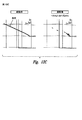
これらの旋回流パターンを図3中にいくぶん概略的に図示する。図3が、渦に関連付けられる空気流を正確に表わすのではなく、全体的なパターンを示すように向けられていることを理解すべきである。図から分かるように、渦の外側部分には上向きの洗流32があり、渦の内側には下向きの洗流34がある。図から分かるように、2つの下向きの洗流ゾーン34の間を進む飛行機36に対して、(着陸時の)高度の損失または上昇レートの損失がある。上向きの洗流32へと進んでいる38で示される飛行機に対して、飛行機にロールモーメントが加えられることがある。2つの渦22を通って横断的に移動している、40で示される飛行機に対して、飛行機40に加えられる垂直方向の負荷の突然の変化により、飛行機40に実質的な空力的応力が加えられることがある。
These swirl flow patterns are somewhat schematically illustrated in FIG. It should be understood that FIG. 3 is directed to show the overall pattern rather than accurately representing the air flow associated with the vortex. As can be seen, there is an
本発明のこれらの実施形態のさまざまな観点の説明を容易にするために、翼先端部から発生される渦は、図4において断面が概略的に示されており、渦芯44と、芯を囲む主要な渦流れ領域46と、主要な渦流れ領域46を囲む外周流れ領域48とを有するものと考えることができる。渦芯44と主要な渦流れ領域46と外周流れ領域48との間にはっきりした境界線がないことは明らかである。
In order to facilitate the description of the various aspects of these embodiments of the present invention, the vortex generated from the blade tip is shown schematically in cross-section in FIG. It can be considered to have a surrounding main
上述の文面は背景情報として与えられており、これから本発明の実施形態を説明する。上述の説明において、用語“エーロフォイル”は、空力的な機体全体を指すことを意味しており、その断面または断面構成を意味することを意図していない。また、より広い範囲内において、エーロフォイルは、翼や、後縁フラップや、前縁フラップまたはスラットや、ウィングレットや、制御面などを含む、さまざまな空力機体を含むことを意味する。 The above-mentioned text is given as background information, and an embodiment of the present invention will now be described. In the above description, the term “airfoil” is meant to refer to the entire aerodynamic airframe and is not intended to mean its cross-section or cross-sectional configuration. Also, within a broader range, an airfoil is meant to include a variety of aerodynamic bodies including wings, trailing edge flaps, leading edge flaps or slats, winglets, control surfaces, and the like.
この実施形態のエーロフォイル渦消散システム50を、そのノズルセクション52とともに、図6、図7、および図8に関連してこの文面において以下により詳細に説明する。しかしながら、この渦消散システム50の機能を最初に予備的に説明することにより、システム50がよりよく理解されると信じる。これは図5Aないし図5Dに関連してなされる。
The airfoil
図5Aにおいて、右翼14の外縁部分20が示され、ノズル整列軸が54で示される。その軸54の位置において、可動カバープレートまたはパネル56があり、これは、ジェット気流放出開口部を閉じ、その周囲の境界が図5Aにおいて58で示されている。また図5Aにおいて、横方向ジェット気流放出軸60(以下、横向きの放出方向60と呼ぶ)が示されており、横向きの放出方向60は、ノズル整列軸54に対して垂直な、実質的な整列成分を有し、スパン方向軸28および翼弦軸30により規定される(およびこれらと一致する)上述の整列面に対して平行な、実質的な整列成分も有する。飛行機10の巡航モードにおいて、カバープレート56は閉じられた位置にあり、飛行機が着陸または離陸および上昇するときに開かれる。
In FIG. 5A, the
図5Bにおいて、この横向きの放出方向60に対してほぼ平行であり、かつ、この横向きの放出方向60と一致する(またはその近傍にある)方向に放出されているジェット気流62が示される。上で示したように、ジェット気流62の放出は通常、離陸または着陸中にしか行なわれない。以下により詳細に開示するように、図5Cに示すように、ジェット気流62を上方に傾斜された方向にも放出でき、図5Dに示すように、ジェット気流62を下方に傾斜された方向にも放出できるように、上述のノズルセクション52を動作できる。さらに、この実施形態の動作モードにおいて、ジェット気流62がより高い周波数とより低い周波数とで上下のサイクルで循環するように、図5Cの位置と図5Dの位置との間の上下の動きを、異なる動作モードで行うことができる。これらの効果は渦42の消散に寄与し、このことは、この文面において以下により詳細に論じられる。
In FIG. 5B, a
ここで図6、図7および図8を参照して、ノズル放出セクション52をより詳細に説明する。図6、図7および図8はいくぶん概略的であり、最適化された構造上の構成設計を示すのではなく、基本的な機能を実行する構成要素を有する設計を示すように向けられていることを理解すべきである。この設計が航空機の一部として実際に実現される状況では、構成要素のそれぞれは、軽量で構造的に堅固で機能的であるという設計目標に一致し、ジェット気流62の加圧、閉じ込めおよび放出を実現し、さらに、翼または他のエーロフォイルの輪郭に適切に適合するよう構成される。
The nozzle discharge section 52 will now be described in more detail with reference to FIGS. 6, 7 and 8. FIG. FIGS. 6, 7 and 8 are somewhat schematic and are not intended to show an optimized structural composition design, but rather to show a design with components that perform basic functions. You should understand that. In situations where this design is actually implemented as part of an aircraft, each of the components meets the design goal of being lightweight, structurally robust and functional, and pressurizing, confining and releasing the
図6において、ノズルセクション52の基本的な構成要素が示され、ノズルセクション52の基本的な構成要素は、ハウジングセクション64(以下ハウジング64と呼ぶ)と、ノズル放出セクション66とである。ここで示すように、ハウジング64は、上方または下方の壁68および69と、加圧されたプレナムチェンバー74を集合的に規定する後壁70および端壁72とを有する単一の細長いハウジングとして示される。このハウジング64は、翼14の外端部分20内に位置付けられ、したがって、ハウジング64は、翼14のその部分の範囲内で適切に適合できるような形状である。
In FIG. 6, the basic components of the nozzle section 52 are shown. The basic components of the nozzle section 52 are a housing section 64 (hereinafter referred to as housing 64) and a nozzle discharge section 66. As shown here, the
加圧空気入口76は、適切な源から加圧空気を受け取る。例えば、加圧空気は、ジェットエンジンのコンプレッサセクションまたは他のいくつかの源から抽気できる。また、入口76は単一の入口として示されているが、これは、複数の入口を備えた多岐管の方法で、または他のいくつかの構成で構成できる。
The
ノズル放出セクション66は全体的に細長い構成を有し、ノズル装着部材78を備える。ノズル装着部材78が有する細長い円筒形の壁80の全体的な構成は、ハウジング64の前方部分に形成された細長い前方端部開口領域82においてぴったりと嵌合している。この端部開口領域82は、2つの対向して位置付けられている円筒形のカーブ面84を含み、カーブ84は円筒形の壁80の形状と一致し、カーブ面84は円筒形の壁80と実質的に気密性のあるシールを形成している。
The nozzle discharge section 66 has a generally elongated configuration and includes a
細長い円筒形の壁80は両端が閉じられており、1つ以上の後方開口部86を有し、後方開口部86は、ハウジング64のプレナムチェンバー74に対して開いており、円筒形の壁80により規定されるノズルプレナムチェンバー88に対して開いている。
The elongated
円筒形の壁80の前方部分に位置する複数の個々のノズル部材90は、ノズル放出セクション66のノズル放出部分92を集合的に形成する。これらのノズル部材90は、横方向放出軸60において互いに整列するように図6中で示され、それによりこれらは、上述のジェット気流62を集合的に形成する。こうして、加圧空気が、加圧空気入口すなわち入口76を通ってプレナムチェンバー74に送り出され、そこからノズルプレナムチェンバー88に入るとき、加圧空気がこれらのノズル部材90から放出されてこのジェット気流62を形成する。
A plurality of
円筒形の壁80は、ハウジング64の細長い前方端部開口領域82を規定する円筒形のカーブ面84において回転可能に装着され、その回転軸は94で示されている。図7の破線で示したように、これにより、ノズル90が水平に向けられている中央の整列位置から、図7中で示した破線位置に上方向または下方向に、ノズル部材90を動かすことが可能となる。この実施形態において、上方への回転量は、例えば、直角三角形の3分の1(例えば、約30°)とすることができ、下方へも同じ回転角度とすることができ、これにより、移動の総経路は例えば約60°とすることができる。
角度方向のさまざまな位置にノズル部材90を動かすために、図8において92で概略的に示されるような、適切な作動メカニズムを設けることができる。ノズル装着部材78はシャフト96に接続し、シャフト96はレバーアーム98に接続し、レバーアーム98は作動アーム100によって動かされる。他の実施形態において、ベルクランクや、ギヤドライブや、あるいは、電気式、空気圧式または液圧式の位置決めデバイスなどの、他のさまざまな装置を使用して、ノズル装着部材78の位置を変えることができる。簡潔にするために、これらのさまざまな設計オプションは、ここでは詳細には記述しない。
Appropriate actuation mechanisms can be provided to move the
また、加圧空気をノズル部材90に方向付けるためのさまざまな構成が存在し得る。例えば、加圧空気入口76をノズル装着部材78に直接接続して、円筒形の壁80を通って導くことができ、または、円筒形の装着部材78の端壁に回転嵌合によって加圧空気入口76を取付けることも可能である。この配置では、プレナムチェンバー74を有するハウジング64の現在の構成が削除される。翼の外縁部分20上にノズルアセンブリ50を位置付ける制約により、これらのスペース上の制約に適合する構成にハウジング64をして、さらに、ノズル部材90を通して適切なパターンの加圧空気を放出するのに十分な容積のプレナムチェンバーを設けることがより望ましい。
There may also be various configurations for directing pressurized air to the
ノズルアセンブリ52を位置付けることに関して、ハウジング64およびノズル装着部材78は、翼14の外縁部分20における固定位置にあってもよい。この例では、渦消散システム50が動作可能になるとき、上述のカバープレート56がジェット気流放出開口部58から離れるように移動され、それにより、ジェット気流62が渦42に放出されるように、ノズル部材90が開口部58を通してジェット気流62を方向付けることができる。
With respect to positioning the nozzle assembly 52, the
カバープレートまたはパネル56は、さまざまな方法でそのカバー位置から解放位置に移動できる。例えば、このカバープレート56はカーブした構成を有することができ、開口領域から出て収容位置にスライドするように移動可能であってもよい。
The cover plate or
飛行機の翼などのエーロフォイルにおいて、平面図では、外端部分は、前方から後方への外側に膨らむなだらかなカーブを有しており、それ故に、翼の端部先端のカーブした外形の中間長さにおいては、胴体からさらに外に向かって短い距離が位置付けられている。ノズル部材90を翼または他のエーロフォイルの外縁部分に比較的近接して配置するために、ノズル部材90の整列位置はなだらかなカーブになる。したがって、図6中で示した構成は、翼または他のエーロフォイルの外縁の形状に適合するカーブにこれらのノズル部材90を配置するように修正でき、さらに、上方向および下方向に回転できる。この構成を得るためにさまざまなオプションがある。例えば、ノズル装着部材78をハウジング64の全長にわたって単一構造として製造する代わりに、ノズル装着部材78を、わずかに異なる回転軸64を中心として回転可能な複数の個々のセグメントに配置し、それにより、これらを、翼先端部のラインの外側のカーブに対してより密接に適合させることができる。他の配置も利用可能であり、これらは当業者には周知であるのでこの文面では詳述しない。
In an airfoil such as an airplane wing, in the plan view, the outer end portion has a gentle curve that bulges outward from the front to the rear, and hence the intermediate length of the curved outline at the tip of the wing end. In this case, a short distance is located further outward from the body. In order to position the
先に示したように、飛行機12が巡航モードであるとき、渦消散システム50は使用されず、翼におけるカバープレート56の後方に隠れたままである。次に、カバープレート56が解放位置に移動され、2つの翼先端部の渦の減衰の促進が高く望まれるときに、渦消散システム50は、離陸モードおよび着陸モードの際に一般的に使用される。
As indicated above, when the
ジェット気流62が、この位置で、および上述した配向および方向で渦22に注入された場合、渦中へのジェット気流62の流入は、渦の芯が形成されている位置であり、形成されている渦の芯の周りにおいて、エーロフォイルの下方面からの空気の、横向きで外方向かつ上方向へのカーブした渦流が発生する。したがって、分析によって示されるように、この位置でのジェット気流62の流入は、発生した渦中の空気流に影響を及ぼすのに特に有効であり、それにより、全体的な効果として、重要な位置での消散が開始され、渦の減衰が実質的に促進される。
When the
さらに、図5Aないし図5Dに関連して説明したように、ノズル装着部材78を周期的に上下に循環させる動作モードがあり、それにより、連続的なサイクルで、ノズル部材90は図5C中で示した上方位置に移動し、次に、図5Bの中間位置を通って図5Dの下方位置へと下がり、再び上昇して図5Cの位置に戻る。
In addition, as described in connection with FIGS. 5A-5D, there is a mode of operation that periodically circulates the
本発明のこの実施形態により達成される結果は、計算流体力学手順によりシミュレートおよび分析された。最終的な進入状態を表すために、動作の有効性は、8度の迎角でマッハ0.25の自由流マッハ数を有する垂直な壁に装着された翼について評価された。この動作モードは、強力な先端部の渦を有するコヒーレントな伴流となる。上述した本発明のこの実施形態が利用されるとき、渦が著しく拡散されて、流れが影響を受けることが見い出された。 The results achieved by this embodiment of the invention were simulated and analyzed by computational fluid dynamics procedures. To represent the final approach condition, the effectiveness of the operation was evaluated for a wing mounted on a vertical wall with a free flow Mach number of Mach 0.25 at an angle of attack of 8 degrees. This mode of operation results in a coherent wake with a strong tip vortex. It has been found that when this embodiment of the invention described above is utilized, the vortices are significantly diffused and the flow is affected.
ノズル90が一緒に、ノズル整列軸74から上方と下方とにそれぞれ30°の範囲で上下に動かされるケースにおいて、10.7Hzの周波数(0.093秒で1サイクル)では、渦に対する効果が、図9A、図9B、図9C−1、図9C−2、図9D−1および図9D−2に図示したように、翼先端部の流れの線の跡により表わされる。図9A、図9C−1および図9C−2においては、渦へのジェット気流62の噴出はなく、図9B、図9D−1および図9D−2は、ジェット気流62が10.7Hzで上下に60°の動きで噴出されている渦を示す。ジェットの周期的な運動により提供される断続的な混合が先端領域における流れを乱し、そして、強度を減少させ交差平面においてそれを拡散することにより、航跡渦の発生を変えることを、これらの“スナップショット”が示す。
In the case where the
垂直な動きを追跡するのに使用できるいくつかの方法がある。ファーフィールド(far field)伴流構造が図10A、図10B、および図10C中に表されており、ここでは、先端部の渦は、全圧力損失、交差流、および速度の流れ方向成分により追跡される。渦芯はそれぞれの流れ特性の等値面によって表わされており、移動するジェットのために渦の強度が著しく低減することが明確に示されている。 There are several methods that can be used to track vertical movement. A far field wake structure is depicted in FIGS. 10A, 10B, and 10C, where the tip vortex is tracked by total pressure loss, cross flow, and velocity direction component of velocity. Is done. The vortex core is represented by an isosurface of the respective flow characteristics, clearly showing that the strength of the vortex is significantly reduced due to the moving jet.
10.7Hzの周波数での渦の芯に沿った流れの発生に関する診断を図11A、図11Bおよび図11C中に示す。噴出動作の瞬間から0.093秒の時間間隔のシーケンスにおける流れ特性が、上方のグラフで渦芯に沿って示されている。また、下方のグラフでは、x=2850で渦芯を通過する垂直線に沿った特徴が示されている。擾乱されていない渦が太い実線の曲線により示される。他の曲線は、信号が下流へ(正のx方向に)進んでいる場合に連続的な時間間隔で渦の特徴に与えられる制御メカニズムの影響を表わす。乱れの波の前方は時間シーケンスにおける最後のスナップショットに対応し、それは破線の曲線により表されている。破線は、噴出適用の開始から0.558秒での渦の状態を示している。この結果は、アクティブなシステムが、全圧力損失と、(速度の接線成分で表わされる)交差流速度と、渦度の流れ方向成分とにより測定される渦の強度を低減させるのに非常に有効であることを示している。 Diagnosis regarding the generation of flow along the vortex core at a frequency of 10.7 Hz is shown in FIGS. 11A, 11B and 11C. The flow characteristics in a sequence with a time interval of 0.093 seconds from the moment of ejection are shown along the vortex core in the upper graph. In the lower graph, a feature along a vertical line passing through the vortex core at x = 2850 is shown. Undisturbed vortices are indicated by thick solid curves. The other curve represents the effect of the control mechanism on the vortex features at successive time intervals as the signal travels downstream (in the positive x direction). The front of the turbulence wave corresponds to the last snapshot in the time sequence, which is represented by the dashed curve. The broken line shows the state of the vortex at 0.558 seconds from the start of spray application. This result shows that the active system is very effective in reducing the vortex strength measured by the total pressure drop, the crossflow velocity (expressed by the tangential component of velocity) and the flow direction component of vorticity. It is shown that.
ノズル90の上下するサイクルはまた、おおよそ1Hz(すなわち、1秒よりも少し短い時間で上下運動の1サイクル)のような、より低い周波数で有効に使用できる。この効果は、擾乱されていない渦と、1.07Hz周波数で本発明の渦消散デバイスを動作させたものとを比較することにより分析された。1.07Hzでの動作の結果が図12A、図12Bおよび図12Cに示されており、これは、振動するジェット気流62が下流に伝搬する渦に沿って周期的な擾乱を導入することを示している。この連続的な励振により、個々の渦セグメントの不安定と破壊が生じる。
The up and down cycle of the
図13A、図13Bおよび図13Cは、噴出適用開始からさまざまな時間間隔での、渦フィラメントに沿った乱れの波を描写する。周期的に、全圧力損失が0.5%未満に低減され、これが元の渦の強度の約85%の低減に至ることが示されている。最大の接線速度は、元の擾乱されていない渦の約50%に周期的に低減される。同様に、最大渦度が約3分の2だけ低減されている。実際面では、アクティブな制御を使用することにより実現される交差流の実質的な低減を考えると、後続の航空機は上下動する飛行を経験するが、危険なローリング運動を被ることはないだろう。 13A, 13B, and 13C depict turbulent waves along the vortex filament at various time intervals from the beginning of the jet application. Periodically, the total pressure loss has been reduced to less than 0.5%, which has been shown to lead to an approximately 85% reduction in the strength of the original vortex. The maximum tangential velocity is periodically reduced to about 50% of the original undisturbed vortex. Similarly, the maximum vorticity is reduced by about two thirds. In practice, given the substantial reduction in crossflow achieved by using active control, subsequent aircraft will experience flying up and down but will not suffer dangerous rolling motion. .
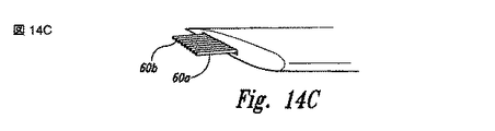
ここで、図14A、図14B、図14C、図14Dおよび図14Eを参照する。これらは、いくつかの相違はあるが図5B、図5C、および図5D中で示したのと類似の方法を図示する連続図である。この例において、ジェットノズル90は前方セクションと後方セクションとに分けられており、前方および後方セクションのそれぞれは、ノズル90の他の組とは異なるパターンで上方向および下方向に移動できる。
Reference is now made to FIGS. 14A, 14B, 14C, 14D and 14E. These are sequential diagrams illustrating a method similar to that shown in FIGS. 5B, 5C, and 5D with some differences. In this example, the
図14Aにおいて、ジェット気流部分の前方の組62aと、ジェット気流部分の後方の組62bとが示される。これらの両方は、図14A中に示されるのと同じ位置にある。図14B中で示したように、前方の組62aは下方に30°移動し、一方、後方の組62bは上方に30°移動している。図14Cにおいて、ジェット気流部分の2つのセクション62aおよび62bはそれらの配向方向が反転しており、図14Cにおいて、水平位置の方にさらに移動し、水平位置を通って移動するが、さらに反対の方向に回転する。図14D中で示したように、それらは、前方のジェット気流部分62aが上方に30°移動し、後方のジェット気流部分62bが下方に30°移動している。次に、図14E中で示したように、2つのジェット気流部分62aおよび62bは逆方向に移動し、同時に水平位置を通過するが、反対の方向に進む。こうして、このジェット気流の振動は、はさみパターンと呼ぶことができるものを形成する。 In FIG. 14A, a set 62a in front of the jet stream portion and a set 62b in the rear of the jet stream portion are shown. Both of these are in the same position as shown in FIG. 14A. As shown in FIG. 14B, the front set 62a moves downward by 30 °, while the rear set 62b moves upward by 30 °. In FIG. 14C, the two sections 62a and 62b of the jet stream portion are reversed in their orientation direction, and in FIG. 14C, they move further toward the horizontal position and move through the horizontal position, but the opposite Rotate in the direction. As shown in FIG. 14D, the front jet stream portion 62a moves upward by 30 ° and the rear jet stream portion 62b moves downward by 30 °. Next, as shown in FIG. 14E, the two jet airflow portions 62a and 62b move in opposite directions and simultaneously pass the horizontal position but proceed in opposite directions. Thus, this jet stream vibration forms what can be referred to as a scissor pattern.
また、ジェット気流の角度配向は、図5Aないし図5D中に示したものから角度的にシフトできる。エーロフォイルの基準面に対して中間位置を水平(すなわち、平行)にしておく代わりに、中立位置は外方向かつ下方向に30°傾斜される。こうして、上方位置に対して上方向に移動する場合、ジェット気流は水平になり、下方位置に回転する場合、ジェット気流は水平から60°の角度で下方向かつ外方向に傾斜することになる。この動作モードでは、かなり満足の行く結果が達成されたことが見い出されている。 Also, the angular orientation of the jet stream can be angularly shifted from that shown in FIGS. 5A-5D. Instead of keeping the intermediate position horizontal (ie, parallel) to the airfoil reference plane, the neutral position is tilted 30 ° outward and downward. Thus, when moving upward with respect to the upper position, the jet stream is horizontal, and when rotating to the lower position, the jet stream is inclined downward and outward at an angle of 60 ° from the horizontal. In this mode of operation, it has been found that quite satisfactory results have been achieved.
本発明の実施形態のうちの少なくともいくつかにおいて、ノズルセクションは、エーロフォイルの外端部分において、またはその近傍において概して前方向から後方向に延在する整列位置に位置付けられる。ジェット気流が放出される領域の長さ寸法は、例えば、エーロフォイルの外側先端部の端部分における翼弦長の長さの3分の1とすることができ、翼弦長のおおよそ4分の1から2分の1のより広い範囲とすることができる。しかしながら、本発明のより広い範囲内では、これは、たとえば翼弦長の60%、70%、80%、90%または100%に増やすことができ、あるいは、エーロフォイルの外側先端部における翼弦長の35%、30%、25%、20%、またはおそらく15%とすることができる。 In at least some of the embodiments of the present invention, the nozzle section is positioned in an aligned position extending generally from the front to the rear at or near the outer end portion of the airfoil. The length dimension of the area where the jet stream is emitted can be, for example, one third of the chord length at the end of the outer tip of the airfoil, and is approximately four minutes of the chord length. It can be a wider range from one to a half. However, within the broader scope of the invention, this can be increased to, for example, 60%, 70%, 80%, 90% or 100% of the chord length, or the chord at the outer tip of the airfoil It can be 35%, 30%, 25%, 20%, or perhaps 15% of the length.
ノズル部材90から放出されるジェット気流の速度は、例えば、約マッハ0.62とすることができる。しかしながら、他のさまざまな要因次第で、これは、マッハ0.7、0.8、0.9、または、ことによるとより大きい値にまで値を増加させることができる。また、この値は、例えば、マッハ0.6、0.5、0.4、0.3、または、ことによるとより小さい値に減少できる。
The velocity of the jet airflow emitted from the
本実施形態のより広い範囲内では、往復運動を有するジェット気流は、異なる角度配向に向けることができ、異なる角度配向を通じて往復するように動かすことができ、および/または、渦を形成する空気流の他の位置に向けることができる。 Within the broader scope of this embodiment, a jet stream having a reciprocating motion can be directed to different angular orientations, can be moved to reciprocate through different angular orientations, and / or airflow forms vortices. Can be directed to other locations.
ノズルセクション50の渦放出部分52の1つの構成において、複数のノズル部材が整列位置に沿って位置付けられる。ノズルのそれぞれは、例えば、より高い速度が必要とされる場合、簡単な変換ノズルまたは先細/末広ノズルであってもよい。ノズルの断面は円形または他の適切な形状であってもよい。ノズルの断面の形状は、ノズルの長さに沿って変化してもよい(例えば、円形の断面から、ノズル出口において楕円の断面に変化してもよい)。作動システムの下流のノズルおよび分配ダクト構造は、当業者によく知られている技術を使用して、圧力損失を最小限にするよう設計できる。しかしながら、これらの実施形態のより広い範囲内では、幅寸法よりも大きい長さ寸法を有する連続的なスロットの形態で、より細長いノズル放出部分があってもよい。
In one configuration of the vortex shedding portion 52 of the
1つの実施形態において、本システムは、600,000ポンドの飛行機のために設計される。1つの設計において、計算された設計パラメータは以下のとおりである。ノズルセクションの翼弦方向の全長は43インチであり、均等に間隔をあけて配置された13個の円形の放出オリフィスを有し、放出オリフィスはそれぞれ、3.2インチの直径を有している。ジェット気流として放出される空気の速度はマッハ0.62で放出される。 In one embodiment, the system is designed for a 600,000 pound airplane. In one design, the calculated design parameters are as follows: The chord length of the nozzle section is 43 inches and has 13 circular discharge orifices that are evenly spaced, each discharge orifice having a diameter of 3.2 inches. . The velocity of the air released as a jet stream is released at Mach 0.62.
別の設計において、同じ600,000ポンドの飛行機に対して、放出速度がマッハ0.62である場合、ノズル放出セクションの全長は35インチであり、3.9インチの放出オリフィスの内径をそれぞれ有する、9個のノズル部材がある。 In another design, for the same 600,000 pound airplane, if the discharge rate is Mach 0.62, the total length of the nozzle discharge section is 35 inches, each having a discharge orifice inner diameter of 3.9 inches There are nine nozzle members.
さらに第3の設計において、同じ飛行機の重量と、同じ放出マッハ数の場合、ノズル放出セクションの全長の寸法は37インチであり、3.7インチの放出オリフィスの内径をそれぞれ有する、10個のノズル部材がある。 Further, in the third design, for the same aircraft weight and the same discharge Mach number, the total length of the nozzle discharge section is 37 inches, with 10 nozzles each having a 3.7 inch discharge orifice inner diameter. There are members.
図15Aないし図23は、本発明のさらなる実施例にしたがった、渦消散デバイスと、結果として得られる予想される流れパターンとを図示する。これらの実施形態のうちの少なくともいくつかの観点において、ジェット流を送り出して、翼先端部の渦を分解またはさもなければ消散させるノズルは、固定された構成を有することができる。したがって、これらのノズルから送り出される流れは、例えば、ノズルを通じて流れをパルス化させることにより、時間とともに変化する質量の流量を有することができる。これらの実施形態の別の観点において、これらのノズルから発出する流れの経時変化の性質は、上述したノズル位置の空間的な変化と組合と組み合わせることができる。ノズルを通る空気流の経時変化の性質を制御できる方法のさらなる詳細を以下に記述する。 15A-23 illustrate a vortex dissipation device and the resulting expected flow pattern in accordance with a further embodiment of the present invention. In at least some aspects of these embodiments, the nozzle that delivers the jet stream to break up or otherwise dissipate the wing tip vortices may have a fixed configuration. Thus, the flow delivered from these nozzles can have a mass flow rate that varies with time, for example, by pulsing the flow through the nozzles. In another aspect of these embodiments, the time-varying nature of the flow emanating from these nozzles can be combined with the spatial variation and combination of nozzle positions described above. Further details of how the time-varying nature of the air flow through the nozzle can be controlled are described below.
図15Aは、渦消散デバイス1530が位置付けられている翼1514を有する航空機1510を概略的に図示する。この実施形態の1つの観点において、航空機1510は高翼構成を有しているが、渦消散デバイスが設置されている航空機は、図1中に示した構成を含むがこれに限定されない幅広いさまざまな他の適切な構成のいずれをも有することができる。これらの実施形態のいずれにおいても、翼1514または他のエーロフォイルは、対向する上面および下面、翼体接合部における翼付け根、ならびに、アウトボードの翼先端部1520を有する。渦消散デバイス1530は、それぞれの翼1514のアウトボードの翼先端部1520に、またはその近傍に装着することができる。他の設置においては、渦消散デバイス1530は、翼1514に加えて、または翼1514の代わりに、他のエーロフォイルの先端部に装着できる。このような他のエーロフォイルは、例えば、後縁デバイス(例えば、後縁フラップ1522、補助翼、フラッペロン、または他の展開可能なデバイス)、前縁デバイス(例えば、前縁スラット)、航空機制御面(例えば、航空機昇降舵および/または水平安定板)、回転翼航空機のブレード、および/またはカナードを含むことができる。渦消散デバイス1530の特徴のさらなる詳細を以下に記述する。これらの特徴のうちの多くの、大きさ、形状および構成は、渦消散装置1530が設置されている特定の航空機およびエーロフォイルに合うように調整できる。したがって、以下の説明および関連した図面において記載したデバイスおよび方法のいくつかの観点は、他の実施形態において他の構成を有してもよい。
FIG. 15A schematically illustrates an
図15Bは、図15A中に示した翼先端部1520および渦消散デバイス1530の拡大された等角図である。いくつかの実施形態においては平坦とすることができ、他の実施形態においては半円筒形とすることができ、さらなる実施形態においては複数の次元で複数の軸を中心としてカーブしたものとすることができる、先端面1521を翼先端部1520は含むことができる。これらの実施形態のいずれにおいても、渦消散デバイス1530は1つ以上のノズル1590(説明のために図15B中には14個が示されている)を含むことができ、ノズル1590はそれぞれ、ノズルオリフィス1591を有している。この実施形態の特定の観点において、ノズルオリフィス1591は、先端面1521とほぼ同一平面となるように位置付けられる。他の実施形態において、ノズルオリフィス1591は(例えば、先端面1521からわずかに凹んでいるなど、)他の構成を有することができる。ノズル1590が使用されていないとき、図5Aに関連して上述したのとほぼ同様の方法で、ノズルオリフィス1591は可動ドアの後方に配置できる。説明のために、このようなカバーを図15B中で示していない。ノズルオリフィス1591は、例えば(図15Bにおいて、第1の、例えば、上方の列1594a、および第2の、例えば、下方の列1594bとして示される)複数の列1594のような特定のパターンで並べることができる。図16Aないし図22に関連してさらに以下に記述するように、ノズル1590を通して方向付けられる空気または別の気体の流れを時間に依存する方法で制御し、変化させて、翼先端部1520から発出している渦の消散を促進できる。
FIG. 15B is an enlarged isometric view of the
図16Aおよび図16Bは、図15Aないし図15B中で示した翼1514の簡単化されたバージョンのコンピュータによる流体力学(CFD)シミュレーションの結果を図示する。CFDシミュレーションを簡単にするために、航空機1510(図15A)の胴体は省かれており、1つの翼1514が、垂直な壁に装着されているかのように分析された。説明のために、翼1514はともに、垂直な壁に対応する対称面に関して折り返されているように示されている。この単純化は、翼先端部の渦のシミュレーションに対して重大な影響を及ぼすものとは考えられない。図示したシミュレーション結果は、0.25の自由流マッハ数および8°の迎角に対応する。
16A and 16B illustrate the results of a computerized hydrodynamic (CFD) simulation of a simplified version of the
図16Aは、渦消散デバイス1530が非作動状態であるとき、すなわち、流体流れがノズル1590(図15B)を通じてアクティブに外に方向付けられないときに結果として生じる、流れ場に対応する流れの線1592aを図示する。流れの線1592aは、最初に翼先端部1520に位置付けられている粒子の流れを表わす。図16A中で図示したように、流れ場は、流れの線1592aによって示される比較的強い翼先端部の渦を含み、翼先端部の渦は、芯軸のまわりにしっかりと巻かれ、しっかりと巻かれた螺旋の状態で翼先端部1520から下流に進む。
FIG. 16A shows a flow line corresponding to the flow field that results when the
図16Bは、加圧空気がノズル1590(図15B)を通して供給されるときに、予想される流れに対応する流れの線1592bを図示する。図16Bにおいて、流れは、約10Hzの周波数ですべてのノズル1590を通して同時にパルス化される。本実施形態の1つの観点において、パルス化された流れは、約0.05秒のパルス幅と約0.05秒のパルス間の間隔とを有する方形波関数にしたがって供給される。他の実施形態において、以下により詳細に記述するように、流れがパルス化される方法は異なっていてもよい。図16Bから明らかなように、ノズルを通して空気流をパルス化することにより、翼先端部1520から発出する渦が擾乱されることが予想される。上述したように、このような擾乱により、後続する航空機に対する渦の潜在的に有害な影響を低減できることが予想される。
FIG. 16B illustrates a
図17Aおよび図17Bは、それぞれ図16Aおよび図16Bに関連して上述したのと同じ流れ場条件でシミュレートされた交差流速度輪郭を図示する。特に、図17Aは、渦消散デバイス1530が非作動状態である間に翼先端部1520の後部におけるいくつかのステーション位置で得られる渦芯1595aと交差流輪郭1593aとを図示する。渦芯1595aおよび強い交差流勾配は、翼先端部1520の下流のかなりの距離にわたって持続する。
FIGS. 17A and 17B illustrate cross flow velocity profiles simulated with the same flow field conditions described above in connection with FIGS. 16A and 16B, respectively. In particular, FIG. 17A illustrates a vortex core 1595a and a
図16Bに関連して上述したように、図17Bは、流れが10Hzでノズル1590を通してパルス化される状態に対する、渦芯1595bと、対応する交差流輪郭1593bとを図示する。このケースにおいて、渦の流れは著しく擾乱され、比較的早く(たとえば、翼先端部1520の後部における短い距離で)分解する。これらの予測される結果は、ノズル1590を通して流れをパルス化することにより、翼先端部の渦を著しく擾乱でき、および/または消散できるという予想をさらに示す。
As described above in connection with FIG. 16B, FIG. 17B illustrates a vortex core 1595b and corresponding cross-flow profile 1593b for the situation where the flow is pulsed through the
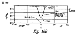
図18Aおよび図18Bは、翼先端部1520の後部におけるステーション位置における、図16Aおよび図16Bに関連して上述したのと同じ流れ場条件でシミュレートされた全圧力レベルを図示する。図18Aは、線1596aにより表わされる、擾乱されていない渦に対してシミュレートされた全圧力レベルを図示する。図18Aはまた、(線1596b1ないし1596b6により表される)約10Hzの周波数でのノズルを通る流体パルスの起動後に、連続的な0.1秒の時間間隔で、擾乱された渦に対する全圧力レベルを図示する。結果的に、図18Aは、予想される全圧力レベルが、線1596aにより示される元の擾乱されていない渦よりもはるかに速く自由流の全圧力状態(たとえば、約1.0の全圧力比)に近づくことを示している。
18A and 18B illustrate the total pressure level simulated at the station position at the rear of the
図18Bは、翼先端部1520の後方における特定の垂直なステーションでのシミュレートされた全圧力レベルを図示する。実線1596aは、擾乱されていない渦の全圧力レベルを表わす。破線1596b6は、約10Hzの周波数でノズルを通る流体パルスの起動後0.6秒の全圧力レベルを表わす。したがって、図18Bは、渦が消散し、全圧力レベルが自由流状態に関連付けられるものに近づく速さ(0.6秒)をさらに図示する。
FIG. 18B illustrates the simulated total pressure level at a particular vertical station behind the
他の実施形態において、ノズルを通る流れは、上述した10Hzのパルス以外の方法で、変化させることができるが、なお、著しい渦の消散を達成できる。例えば、図19は、ノズルを通る流れが(10Hzではなく)1Hzでパルス化されたときの予想される結果を図示しており、ここでは0.5秒の、パルス幅およびパルス間の間隔を有する。図19は、渦芯1995と交差流輪郭1993とを図示する。図19中で示した渦芯1995と図17A中で示した渦芯1595bとを比較することにより、比較的低い周波数パルスでさえ、翼先端部1520から発出する渦の流れを消散させるかなりの能力があることが示される。図19中に示した交差流輪郭1993と、図17A中に示した交差流輪郭1593とを比較することにより、さらに、この予想される結果が示される。
In other embodiments, the flow through the nozzle can be varied in ways other than the 10 Hz pulse described above, but still significant vortex dissipation can be achieved. For example, FIG. 19 illustrates the expected results when the flow through the nozzle is pulsed at 1 Hz (rather than 10 Hz), where 0.5 seconds of pulse width and spacing between pulses are shown. Have. FIG. 19 illustrates a
少なくともいくつかの実施形態において、高周波数パルスおよび低周波数パルスは、異なる方法で翼先端部の渦に影響を及ぼすことが予想される。例えば、高周波数パルスは、翼先端部1520で、またはまさにその近くで、翼先端部の渦を乱し、分解し、および/またはさもなければ崩壊させる傾向があることが予想される。逆に、より低い周波数パルスは翼先端部における流れに乱れを発生させ、これらの乱れがより長期間にわたって発達するかもしれないが、最終的には渦の崩壊および/または分解をも生じさせることが予想される。特定の例において、図17Bと図19との比較は、渦が比較的高い周波数パルス(図17B)にさらされたときには、渦は翼先端部1520により接近して、かつ安定した方法で分解できることを示す。渦がより低い周波数パルス(図19)にさらされたときには、渦は、より長い期間(それゆえに、より長い距離)にわたって、かつ不安定な方法で分解する。いずれの構成においても、パルスが、翼先端部の渦の影響を消散させ、乱し、分解し、および/またはさもなければ低減させることが予想される。
In at least some embodiments, high frequency pulses and low frequency pulses are expected to affect wing tip vortices in different ways. For example, high frequency pulses are expected to tend to disrupt, break up, and / or otherwise collapse the wing tip vortex at or near the
いずれかの所定のノズルを通る流れの量を変化させることに加えて、いずれかの時点で空気流が供給される特定のノズルオリフィスの位置を変化させてもよい。例えば、図19に関連して上述したシミュレーションにおいて、流れは、交互に第1の列1594aと第2の列1594b(図15B)とに供給された。したがって、第1の列1594aにおけるノズル1590は、0.5秒のパルス幅と0.5秒のパルス間の間隔とを有する1Hzでパルス化され、第2の列1594bにおけるノズル1590はまた、第1の列1594aにより供給されるパルスに対して0.5秒だけずらされた方法で、0.5秒のパルス幅と、0.5秒のパルス間の間隔とを有する1Hzでパルス化された。すなわち、流れパルスが第1の列1594a中のノズル1590に供給されたとき、第2の列1594b中のノズル1590は非作動状態になり、逆も同様であった。少なくともいくつかの例において、第1の列1594aと第2の列1594bとに対して流れを交互に供給することにより、翼先端部の渦をより効果的に乱すことができると考えられる。
In addition to changing the amount of flow through any given nozzle, the position of a particular nozzle orifice to which air flow is supplied at any point in time may be changed. For example, in the simulation described above in connection with FIG. 19, flow was alternately supplied to the
図20Aないし図20Dは、異なるときに異なるノズルが空気流を供給する他の実施形態にしたがった代表的な構成を図示する。図20Aは、開いたノズル2098aと、閉じたノズル2097aとの“チェッカー盤”パターンを有するノズル1591を図示する。図20Bは、閉じたノズル2097bが開いたノズル2098bの前方に位置する別の構成を図示する。いずれかの実施形態の1つの観点において、開いたノズル2098bおよび閉じたノズル2097bの構成は、翼先端部の渦を崩壊させるために交替させることができる。他の実施形態において、いくつかのノズル(例えば、後方のノズル)を開けたままにすることがいくつかの飛行条件で特に有益であり、他のノズル(例えば、前方のノズル)を開けたままにすることが他の飛行条件で特に有益であると決定されるかもしれない。したがって、開いたノズルおよび閉じたノズルの選択は、航空機の飛行体制に依存する方法でなされてもよい。他の実施形態において、ノズルは、さまざまな方法で、開いた状態と閉じた状態とを交替させてもよい。これらの実施形態のいずれにおいても、ノズルが作動状態から非作動状態に切り換わる経時変化方法に重ね合わされる経時変化方法で、ノズル1591を通して流れをパルス化してもよい。したがって、作動状態のノズルすなわち開いたノズルを通して流れがパルス化される周波数は、ノズルが作動状態と非作動状態とを交替する周波数と同じであるか、それよりも高いかまたはそれよりも低い。
20A-20D illustrate an exemplary configuration according to another embodiment in which different nozzles provide air flow at different times. FIG. 20A illustrates a
図20Cおよび図20Dは、翼先端部1520で、ノズル流の進行する“波”を作り出すために、ノズルを通る流れを変化させる方法を図示する。例えば、図20Cは、時間T0における、後方に位置付けられた2つの作動状態のノズル2098cと、前方に位置付けられた残りの非作動状態のノズル2097cとを図示する。(図20D中で図示した)T1において、作動状態のノズル2098dは、図20C中に示した構成から1列前方にシフトしており、非作動状態のノズル2097dは、ここでは作動状態のノズル2098dの前方と後方とに位置付けられている。作動状態のノズル2098dの位置は、最も前方のノズルが開くまで同様の方法で連続的に前方にシフトし続けることができる。この時点で、作動状態のノズルの“波”は最も後方の列のノズルから再開でき、または、波は反転して後方向に進行できる。
20C and 20D illustrate a method of changing the flow through the nozzle at the
ノズルの数、ノズルの位置、ノズルを通るパルスのタイミング、および/または他のさまざまな要素が、異なる構成で選択および/または変更できることが理解される。これらのパラメータの選択を駆り立てる要素は、ノズルが設置されている航空機のタイプ(例えば、固定翼または回転翼航空機)、航空機が飛行している特定の飛行条件、システムが設置されているエーロフォイルの形状および構成、ならびに/または、先端部の渦の減衰レートが加速される所望の度合いを含むことができる(しかし、これらに限定されない)。 It will be appreciated that the number of nozzles, the position of the nozzles, the timing of the pulses through the nozzles, and / or various other factors can be selected and / or changed in different configurations. Factors driving the selection of these parameters include the type of aircraft in which the nozzle is installed (eg, fixed wing or rotary wing aircraft), the specific flight conditions in which the aircraft is flying, and the airfoil in which the system is installed. It can include (but is not limited to) shape and configuration and / or the desired degree to which the tip vortex decay rate is accelerated.
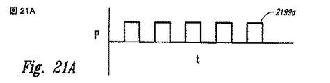
図21Aないし図21Dは、いずれかの所定のノズルを通る流れを変化させる、代表的なパルスプロファイルを図示する。例えば、図21Aは、ステップ関数を有するパルスプロファイル2199aを図示する。各ステップの幅(例えば、流れがノズルを通過している期間)と、補完的なパルス間の間隔(例えば、流れがいずれかの所定のノズルを流れていない期間)は、特定の結果を生じるように選択された方法で変化させることができる。例えば、図21A中で示した実施形態において、パルス幅およびパルス間の間隔は同じであるが、他の実施形態において、パルス幅およびパルス間の間隔は異なっていてもよい。 FIGS. 21A-21D illustrate exemplary pulse profiles that vary the flow through any given nozzle. For example, FIG. 21A illustrates a pulse profile 2199a having a step function. The width of each step (eg, the period during which the flow is passing through the nozzle) and the interval between complementary pulses (eg, the period during which the flow is not flowing through any given nozzle) produces a particular result. Can be varied in a selected way. For example, in the embodiment shown in FIG. 21A, the pulse width and the interval between pulses are the same, but in other embodiments, the pulse width and the interval between pulses may be different.
図21Bは、流れのステップの増加と、その後の流れの漸進的減少と、その後に、いったん流量が0にまで低減した後の即時のステップの増加とを有するパルスプロファイル2199bを図示する。図21Cは、流量の増加が漸進的であり、減少がステップ関数であるパルスプロファイル2199cを図示する。図21C中に示したように、パルスプロファイル2199cは、どの流れも対応するノズルを通って排出されない、パルス間の間隔を含むことができる。図21Dは、シヌソイド状に変化するパルス流量を有するパルスプロファイル2199dを図示する。
FIG. 21B illustrates a pulse profile 2199b having an increase in flow step followed by a gradual decrease in flow followed by an immediate step increase once the flow rate has been reduced to zero. FIG. 21C illustrates a pulse profile 2199c where the increase in flow rate is gradual and the decrease is a step function. As shown in FIG. 21C, the pulse profile 2199c can include an interval between pulses where no flow is ejected through the corresponding nozzle. FIG. 21D illustrates a
図15Aないし図21D中で示した構成と、関係付けられた説明とにより、エーロフォイルデバイスの先端部に形成される渦の流れを崩壊させるために使用できる構成の代表的な例が提供される。これらの先端領域から流れが排出される位置および/または方法は、本発明のさらなる実施形態にしたがった他の方法で、選択および/または変更されてもよい。 The configuration shown in FIGS. 15A-21D and the associated description provide a representative example of a configuration that can be used to disrupt the vortex flow formed at the tip of the airfoil device. . The location and / or method by which flow is discharged from these tip regions may be selected and / or changed in other ways in accordance with further embodiments of the present invention.
図22は、本発明の実施例にしたがって構成された渦消散デバイス2230の構成を図示する。渦消散デバイス2230は、図15Aに関連して上述したのとほぼ同様の方法で配列されたノズル1590およびオリフィス1591を含むことができる。他の実施形態において、ノズルの配列および/または構成は異なっていてもよい。これらの実施例のいずれにおいても、渦消散デバイス2230は、ノズル1590のいずれかを通る流れを選択的に方向付けるかまたは流れを抑制するバルブデバイス2231を含むことができる。本実施形態の特定の観点において、バルブデバイス2231は、圧力の変化を使用して、対応するオリフィスを開いたり閉じたりする流体デバイスとすることができる。圧力の変化は、対応する流体の、または空気のバルブ構成によって提供でき、ノズルを開くかまたは閉じるためにノズル自体に可動部を備える必要はない。適切な装置は、ニュージャージー州のモリスタウンシップのハニーウェル社から入手できる。他の実施形態において、他の適切な、流体の、機械式の、および/または電気機械式の、バルブをバルブデバイス2231に組み込むことができる。
FIG. 22 illustrates the configuration of a
上述の実施形態のいずれにおいても、ノズル1590を通って排出される比較的高圧の空気が高圧空気源2232により供給できる。高圧空気源2232は、航空機エンジンのうちの1つのコンプレッサ段(たとえば、主エンジンまたは補助出力ユニット)を含むことができる。他の実施形態において、ノズル1590に供給される空気は、例えば電気的に駆動されるコンプレッサなどの別個の源により加圧できる。
In any of the embodiments described above, relatively high pressure air discharged through
上述の実施形態のいずれにおいても、渦消散デバイス2230は制御装置2233含むことができる。制御装置2233は、バルブデバイス2231と動作可能に結合されており、各ノズル1590に対する流れをいつどのように調整するかをバルブ装置2231に命令する信号をバルブ装置2231に向けるように構成できる。特定の実施形態において、制御装置2233はコンピュータシステムを含むことができる。したがって、制御装置2233により提供される指示の多くは、プログラム可能なコンピュータにより実行されるルーチンを含む、コンピュータ実行可能な命令の形態を取ることができる。ここで一般的に使用される、用語“コンピュータ”は、何らかのデータプロセッサを指し、マルチプロセッサシステムや、プロセッサベースのまたはプログラム可能な家庭用電子機器や、ネットワークコンピュータや、ミニコンピュータや、ハンドヘルドデバイスや、これらに類似するものを含むことができる。プログラムモジュールまたはサブルーチンは、ローカルおよびリモートのメモリ記憶デバイス中に位置していてもよく、磁気的にまたは光学的に、読取り可能なまたは取外し可能なコンピュータディスクを含むコンピュータ読取可能媒体に記憶または分散されていてもよく、さらに、ネットワークを介して電子的に分散されていてもよい。したがって、制御装置2233は、流れがノズル1590を通して供給される方法を、特に、いくつかのケースにおいては、オペレータにより調整される予め設定された方法を変更するようにプログラムできる。制御装置2233を他の航空機システムに結合して、それにより、対応する航空機が飛行している特定の飛行体制に依存する方法で、ノズルを通して供給される流れの特性を自動的に変更できる。例えば、流れの特性は、航空機が高速巡航状態あるいは、低速進入または離陸状態であるかどうかに依存して自動的に変更できる。ノズル1590が動くよう構成されているとき、制御装置2233はまた、ノズル1590の動きを指示するよう構成できる。
In any of the embodiments described above, the
図23は翼2314の部分概略図であり、本発明のいくつかの追加の実施形態にしたがった、いくつかの異なる渦消散デバイス2330aないしc(総称して渦消散デバイス2330と呼ばれる)を示す。説明のために、これらのデバイスは単一の翼2314上に示されている。さらなる実施形態にしたがった翼は、図示した渦消散デバイス2330のさまざまな組み合せ、または図示したデバイス2330のうちのいずれかを単独で含むことができる。これらのデバイス2330のいずれも、経時変化するジェットパルスを送り出す固定された幾何学的オリフィス、または、安定したジェット流を送り出す空間的に可動なオリフィス、または、空間的に可動であり、かつ経時変化するジェットパルスを送り出すオリフィスを有することができる。
FIG. 23 is a partial schematic view of a
翼2314は、翼先端部の渦消散デバイス2330aを有する翼先端部2320を含むことができる。翼先端部の渦消散デバイス2330aは、上述のいずれにもほぼ類似した構成を有することができる。翼2314はまた、ウィングレット2323を含むことができ、ウィングレット2323は、(オプション的に)ウィングレット先端部の渦消散デバイス2330bを備えた、ウィングレット先端部2325を含むことができる。いくつかの実施形態において、ウィングレット2323がウィングレット先端部の渦消散デバイス2330bを装備するかどうかは、ウィングレット2323の大きさにより決定できる。一般に、ウィングレット2323が大きければ大きいほど、ウィングレット先端部の渦消散デバイス2330bからの可能性のある利点が大きくなる。
The
翼2314はまた、後縁デバイス先端部2324を有する後縁デバイス2322(例えば、フラップ)を含むことができる。後縁デバイス先端部2324は、後縁デバイス先端部の渦消散デバイス2330cを装備できる。再度説明すると、後縁デバイス2322が大きければ大きいほど、後縁デバイス先端部の渦消散デバイス2330cからの予想される利点が大きくなる。
The
前述のことから、説明のために、本発明の特定の実施形態をここで記述してきたが、本発明から逸脱することなくさまざまな修正が実施できることを理解するだろう。例えば、特定の実施形態の文脈に記述した本発明の観点は、他の実施形態において組み合わされるか、または削除されてもよい。特定の例において、上述したノズル流の、経時変化する特徴は、ノズルの空間的に変化する特徴と組み合わされてもよく、このことは、上述されている。特定の実施形態において、空間的に固定された位置を有するがパルス化されたジェット流を送り出すノズルを翼先端部に設けることができ、反対の特徴(空間的に可動であるが安定したジェット流)を有するノズルをフラップまたは他の高揚力装置の先端に設けることができる。他の実施形態において、固定されたノズルおよび可動ノズルの位置は、逆にすることができる。さまざまな実施形態において、ノズルを通してパルス化される流れは、1Hz未満の周波数で、10Hzよりも高い周波数で、または1ないし10Hzの周波数でパルス化できる。 From the foregoing, it will be appreciated that, for purposes of illustration, specific embodiments of the invention have been described herein, but various modifications can be made without departing from the invention. For example, aspects of the invention described in the context of particular embodiments may be combined or deleted in other embodiments. In certain instances, the time-varying characteristics of the nozzle flow described above may be combined with the spatially varying characteristics of the nozzle, as described above. In certain embodiments, a nozzle can be provided at the tip of the wing that has a spatially fixed position but delivers a pulsed jet stream, with the opposite feature (spatially movable but stable jet stream). Can be provided at the tip of a flap or other high lift device. In other embodiments, the positions of the fixed nozzle and the movable nozzle can be reversed. In various embodiments, the flow pulsed through the nozzle can be pulsed at a frequency of less than 1 Hz, at a frequency higher than 10 Hz, or at a frequency of 1 to 10 Hz.
上述したノズルはいずれも、図中で示し、関係付けられた文面に記載したものとは異なる特徴を有することができる。例えば、図中で示したノズルは、ほぼ円形の断面の出口形状を有するが、他の実施形態において、ノズルの出口(および/またはノズルの他の領域)は、円形でない断面の形状を有することができる。複数のノズルを(例えば、スロットの形態で)組み合わせて、個々のノズルの全体数を減らすことができ、他の実施形態において、個々のノズルの数は、図中で示した数から増やすことができる。ノズルは、図中で示し、上述したものとは異なる形状および構成を有することができ、図中で示し、上述したものとは異なる構成を有する航空機に設置できる。多くのケースにおいて、ノズルはエーロフォイルの先端部からの空気を方向付けるよう構成され、いくつかのケースにおいて、ノズルは他の気体または他の流体を方向付けることができる。本発明のいくつかの実施形態に関係付けられた利点をそれらの実施形態の文脈において記述してきたが、他の実施例もまた、このような利点を示すことがあり、すべての実施形態が本発明の範囲内に収まるこのような利点を必ずしも示す必要はない。したがって、本発明は、特許請求の範囲による以外に限定されない。 Any of the nozzles described above may have different characteristics than those shown in the figures and described in the associated text. For example, the nozzle shown in the figure has a substantially circular cross-section outlet shape, but in other embodiments, the nozzle outlet (and / or other areas of the nozzle) have a non-circular cross-sectional shape. Can do. Multiple nozzles can be combined (eg, in the form of slots) to reduce the overall number of individual nozzles, and in other embodiments, the number of individual nozzles can be increased from the number shown in the figure. it can. The nozzle can have a shape and configuration different from that shown and described above, and can be installed on an aircraft having a configuration different from that shown and described above. In many cases, the nozzle is configured to direct air from the tip of the airfoil, and in some cases, the nozzle can direct other gases or other fluids. While advantages associated with some embodiments of the present invention have been described in the context of those embodiments, other examples may also exhibit such advantages, and all embodiments may be It is not necessary to show such advantages that fall within the scope of the invention. Accordingly, the invention is not limited except as by the appended claims.
Claims (10)
第1および第2の対向する流れ面と、先端部(1520)とを有するエーロフォイルと、
前記エーロフォイルにより保持される渦消散デバイス(1530、2230)とを具備し、
前記渦消散デバイス(1530、2230)は、
加圧された流体の源に結合可能な流体フローノズル(1590)であり、各流体フローノズル(1590)が、前記先端部(1520)から外に流体の流れを方向付けるように位置付けられたオリフィス(1591)を有する流体フローノズル(1590)と、
前記流体フローノズル(1590)と流体連通するように結合され、前記オリフィス(1591)を通過する流れを選択的に制御するバルブデバイス(2231)と、
前記バルブデバイス(2231)に動作可能に結合され、前記オリフィス(1591)を通して流れのパルスを送り出すように前記バルブデバイス(2231)の動作を指示する制御装置(2233)とを含む、航空機システムであって、
前記ノズルは、前記エーロフォイルの第1の流れ面の方に位置付けられた第1の列と、前記エーロフォイルの第2の流れ面の方に位置付けられた第2の列とを含む少なくとも2つの列(1594)に配列され、
前記制御装置は、前記第2の列におけるノズルのオリフィスを作動させないようにしている間に、前記第1の列におけるノズルのオリフィスを選択的に作動させ、前記第1の列におけるノズルのオリフィスを作動させないようにしている間に、前記第2の列におけるノズルのオリフィスを選択的に作動させるように前記バルブデバイスに指示することを特徴とする航空機システム。 In aircraft systems,
An airfoil having first and second opposing flow surfaces and a tip ( 1520 );
A vortex dissipation device (1530 , 2230 ) held by the airfoil,
The vortex dissipation device (1530 , 2230 )
Orifices that are fluid flow nozzles (1590) coupleable to a source of pressurized fluid, each fluid flow nozzle (1590) positioned to direct fluid flow out of the tip ( 1520 ). A fluid flow nozzle ( 1590 ) having (1591);
A valve device (2231) coupled in fluid communication with the fluid flow nozzle ( 1590 ) and selectively controlling flow through the orifice (1591);
Operably coupled to the valve device (2231), and a control unit (2233) for instructing the operation of the orifice (1591) the valve device to deliver a flow of pulses through (2231) including, in aircraft systems There ,
The nozzle includes at least two first rows positioned toward the first flow surface of the airfoil and a second row positioned toward the second flow surface of the airfoil. Arranged in a row (1594),
The controller selectively activates the nozzle orifices in the first row while disabling the nozzle orifices in the second row, and activates the nozzle orifices in the first row. An aircraft system, wherein the valve device is instructed to selectively activate nozzle orifices in the second row while not being activated.
前記オリフィス(1591)は第1のオリフィスであり、
前記翼は、先端部(2324)を有する配備可能な高揚力デバイス(2332)を含み、
前記渦消散デバイス(1530、2230)は第2の流体フローノズル(2330c)を含み、各第2の流体フローノズルは前記高揚力デバイスの先端部から外に流体の流れを方向付けるために、前記高揚力デバイスの先端部(2324)に位置付けられたオリフィスを有し、
前記第2の流体フローノズルは、前記加圧された流体の源に結合できる請求項1ないし3のいずれか1項記載のシステム。 A wing (2314) ,
Said orifice (1591) is a first orifice,
The wing includes a deployable high lift device (2332) having a tip ( 2324 );
The vortex dissipation device (1530, 2230) includes a second fluid flow nozzle (2330C), for each of the second fluid flow nozzle directing a flow of fluid to the distal end or al outside of the high-lift device, possess an orifice positioned in the distal portion (2324) of the high-lift device,
4. A system as claimed in any preceding claim, wherein the second fluid flow nozzle can be coupled to the source of pressurized fluid.
エーロフォイルにより揚力を発生させる間に、前記エーロフォイルを大気に通過させることにより、翼先端部の渦を発生させることと、
前記エーロフォイルの前記先端部(1520)から外に複数の流体をパルス状に排出することにより、前記渦を少なくとも部分的に消散させることとを含み、
複数の流体をパルス状に排出することは、第1および第2の列(1594)に配列された複数のオリフィスを通して複数の流体をパルス状に排出することを含み、
前記方法は、前記第2の列におけるノズルのオリフィス(1591)を作動させないようにしている間に、前記第1の列におけるノズルのオリフィスを作動させることと、前記第1の列におけるノズルのオリフィスを作動させないようにしている間に、前記第2の列におけるノズルのオリフィスを作動させることとをさらに含む方法。 In a method of operating an airfoil system,
Generating vortex at the tip of the wing by passing the airfoil through the atmosphere while generating lift by the airfoil;
Wherein by discharging the tip of the airfoil from (1520) a plurality of fluid in a pulsed manner to the outside and a be at least partially dissipating the vortex,
To discharge a plurality of fluid in a pulse shape, the method comprising discharging a plurality of fluid in a pulsed manner through a plurality of orifices arranged in first and second rows (1594),
The method activates the nozzle orifices in the first row while disabling the nozzle orifices (1591) in the second row; and the nozzle orifices in the first row. Activating the orifices of the nozzles in the second row while deactivating them.
Applications Claiming Priority (3)
| Application Number | Priority Date | Filing Date | Title |
|---|---|---|---|
| US11/370,099 | 2006-03-07 | ||
| US11/370,099 US7661629B2 (en) | 2004-02-20 | 2006-03-07 | Systems and methods for destabilizing an airfoil vortex |
| PCT/US2007/005253 WO2008051269A2 (en) | 2006-03-07 | 2007-03-02 | Systems and methods for destabilizing an airfoil vortex |
Publications (3)
| Publication Number | Publication Date |
|---|---|
| JP2009533259A JP2009533259A (en) | 2009-09-17 |
| JP2009533259A5 JP2009533259A5 (en) | 2010-04-15 |
| JP5205284B2 true JP5205284B2 (en) | 2013-06-05 |
Family
ID=39325068
Family Applications (1)
| Application Number | Title | Priority Date | Filing Date |
|---|---|---|---|
| JP2008558306A Active JP5205284B2 (en) | 2006-03-07 | 2007-03-02 | System and method for weakening an airfoil vortex |
Country Status (6)
| Country | Link |
|---|---|
| US (1) | US7661629B2 (en) |
| EP (1) | EP1999014B1 (en) |
| JP (1) | JP5205284B2 (en) |
| AT (1) | ATE465944T1 (en) |
| DE (1) | DE602007006170D1 (en) |
| WO (1) | WO2008051269A2 (en) |
Families Citing this family (24)
| Publication number | Priority date | Publication date | Assignee | Title |
|---|---|---|---|---|
| US8016244B2 (en) * | 2004-02-20 | 2011-09-13 | The Boeing Company | Active systems and methods for controlling an airfoil vortex |
| DE102006008434A1 (en) * | 2006-02-23 | 2007-09-06 | Airbus Deutschland Gmbh | Device for reducing the aerodynamically induced noise at the side edge of a footprint, in particular a high lift surface of an aircraft |
| US7686253B2 (en) * | 2006-08-10 | 2010-03-30 | The Boeing Company | Systems and methods for tracing aircraft vortices |
| KR101112145B1 (en) | 2007-02-09 | 2012-02-22 | 삼성전자주식회사 | A method and apparatus for detecting contention at random access procedure in a wireless communications system |
| GB0802000D0 (en) * | 2008-02-04 | 2008-03-12 | Wingtec Holdings Ltd | Aerofoil control devices |
| JP5286527B2 (en) * | 2009-07-13 | 2013-09-11 | 三菱重工業株式会社 | High lift generator, wing and noise generator for high lift generator |
| WO2011070532A1 (en) * | 2009-12-10 | 2011-06-16 | University Of The Witwatersrand, Johannesburg | Aircraft wingtip arrangement |
| US8413501B2 (en) * | 2010-03-26 | 2013-04-09 | The Boeing Company | Wake measurement probe |
| GB2468978B (en) * | 2010-04-27 | 2012-04-04 | Aerodynamic Res Innovation Holdings Ltd | Fluid flow control device for an aerofoil |
| GB201011843D0 (en) * | 2010-07-14 | 2010-09-01 | Airbus Operations Ltd | Wing tip device |
| GB201103122D0 (en) * | 2011-02-23 | 2011-04-06 | Airbus Uk Ltd | Composite structure |
| US20170088254A1 (en) * | 2011-03-10 | 2017-03-30 | RuiQing Hong | Ultra-High-Pressure Fluid Injection Dynamic Orbit-Transfer System and Method |
| CN102167162A (en) * | 2011-03-10 | 2011-08-31 | 洪瑞庆 | Ultra-high pressure fluid jetting power track transferring system and method for aircraft |
| US9132909B1 (en) * | 2011-03-11 | 2015-09-15 | The United States Of America As Represented By The Administrator Of The National Aeronautics And Space Administration | Flap edge noise reduction fins |
| US9227719B2 (en) * | 2011-03-11 | 2016-01-05 | The United States Of America As Represented By The Administrator Of The National Aeronautics And Space Administration | Reactive orthotropic lattice diffuser for noise reduction |
| US8632031B2 (en) * | 2011-04-11 | 2014-01-21 | The Boeing Company | Systems and methods for attenuation of noise and wakes produced by aircraft |
| RU2469411C1 (en) * | 2011-06-02 | 2012-12-10 | Федеральное государственное унитарное предприятие "Государственный научно-исследовательский институт авиационных систем" | Dataware of aircraft flight safety in vortex field |
| RU2477893C1 (en) * | 2011-09-30 | 2013-03-20 | Федеральное государственное унитарное предприятие "Государственный научно-исследовательский институт авиационных систем" | Method for provision of aircraft flight vortex safety |
| US9896192B2 (en) | 2011-12-13 | 2018-02-20 | Lockheed Martin Corroration | Minimally intrusive wingtip vortex wake mitigation using microvane arrays |
| US10132042B2 (en) | 2015-03-10 | 2018-11-20 | The Procter & Gamble Company | Fibrous structures |
| GB2535488A (en) * | 2015-02-17 | 2016-08-24 | Airbus Operations Ltd | An arrangement for effecting movement of a wing tip device between a flight configuration and a ground configuration |
| DE102015107626B4 (en) * | 2015-05-15 | 2019-11-07 | Airbus Defence and Space GmbH | Flow control device, fluid dynamic profile body and flow control method with sound wave generation |
| US11408129B2 (en) | 2018-12-10 | 2022-08-09 | The Procter & Gamble Company | Fibrous structures |
| CN112810803A (en) * | 2021-02-22 | 2021-05-18 | 中国民用航空飞行学院 | Aircraft wake flow adjusting device for accelerating wingtip vortex dissipation |
Family Cites Families (63)
| Publication number | Priority date | Publication date | Assignee | Title |
|---|---|---|---|---|
| US2477461A (en) * | 1943-07-29 | 1949-07-26 | United Aircraft Corp | Rotating jet device for airfoils |
| US2650781A (en) * | 1950-08-11 | 1953-09-01 | United Aircraft Corp | Boundary layer control for aircraft |
| US3090584A (en) * | 1956-08-15 | 1963-05-21 | Power Jets Res & Dev Ltd | Aircraft |
| US3012740A (en) * | 1958-04-04 | 1961-12-12 | Fairchild Stratos Corp | Aircraft boundary layer control system |
| US3480234A (en) * | 1967-08-18 | 1969-11-25 | Lockheed Aircraft Corp | Method and apparatus for modifying airfoil fluid flow |
| DE1756541C3 (en) | 1968-06-04 | 1974-10-24 | Messerschmitt-Boelkow-Blohm Gmbh, 8000 Muenchen | Airplane with a blower |
| US3596854A (en) * | 1969-06-09 | 1971-08-03 | William R Haney Jr | Vortex generator for airfoil structures |
| US3604661A (en) * | 1969-09-25 | 1971-09-14 | Robert Alfred Mayer Jr | Boundary layer control means |
| US3692259A (en) * | 1970-06-26 | 1972-09-19 | Shao Wen Yuan | Wing-tip vortices control |
| US3761929A (en) * | 1971-02-24 | 1973-09-25 | Us Navy | Radar spoof |
| US3845918A (en) * | 1972-12-07 | 1974-11-05 | Rochester Applied Science Ass | Vortex dissipator |
| US3841587A (en) * | 1973-03-16 | 1974-10-15 | L Freed | Vortex arrestor and visualization system |
| US3881669A (en) * | 1973-05-16 | 1975-05-06 | Martin Lessen | Method and apparatus for elimination of airfoil trailing vortices |
| US3974986A (en) * | 1973-05-29 | 1976-08-17 | Johnstone Edmund H | Aircraft wing vortex deflector |
| US3936013A (en) * | 1973-12-17 | 1976-02-03 | Shao Wen Yuan | Vortex control |
| US3984070A (en) * | 1974-05-24 | 1976-10-05 | The United States Of America As Represented By The Administrator Of The National Aeronautics And Space Administration | Wingtip vortex dissipator for aircraft |
| US3997132A (en) * | 1974-12-11 | 1976-12-14 | The Garrett Corporation | Method and apparatus for controlling tip vortices |
| JPS52121297A (en) * | 1976-04-03 | 1977-10-12 | Masaaki Kusano | High lift apparatus |
| US4477042A (en) * | 1981-01-19 | 1984-10-16 | Griswold Ii Roger W | Vortex alleviating wing tip |
| US5150859A (en) * | 1986-12-22 | 1992-09-29 | Sundstrand Corporation | Wingtip turbine |
| US4860976A (en) * | 1987-10-05 | 1989-08-29 | The Boeing Company | Attached jet spanwise blowing lift augmentation system |
| JPH04108095A (en) * | 1990-08-28 | 1992-04-09 | Mitsubishi Heavy Ind Ltd | Aircraft |
| US5158251A (en) * | 1990-11-16 | 1992-10-27 | The United State Of America As Represented By The Secretary Of The Navy | Aerodynamic surface tip vortex attenuation system |
| WO1993022196A1 (en) * | 1992-04-28 | 1993-11-11 | British Technology Group Usa Inc. | Lifting body with reduced-strength trailing vortices |
| JP2951540B2 (en) | 1994-06-30 | 1999-09-20 | 川田工業株式会社 | Noise reduction device for rotorcraft |
| US5634613A (en) * | 1994-07-18 | 1997-06-03 | Mccarthy; Peter T. | Tip vortex generation technology for creating a lift enhancing and drag reducing upwash effect |
| JPH08133188A (en) * | 1994-11-07 | 1996-05-28 | Mitsubishi Heavy Ind Ltd | Resistance reducing device for wing |
| US5755408A (en) * | 1995-04-03 | 1998-05-26 | Schmidt; Robert N. | Fluid flow control devices |
| US6123145A (en) * | 1995-06-12 | 2000-09-26 | Georgia Tech Research Corporation | Synthetic jet actuators for cooling heated bodies and environments |
| US5758823A (en) * | 1995-06-12 | 1998-06-02 | Georgia Tech Research Corporation | Synthetic jet actuator and applications thereof |
| US5806807A (en) * | 1995-10-04 | 1998-09-15 | Haney; William R. | Airfoil vortex attenuation apparatus and method |
| US5813625A (en) * | 1996-10-09 | 1998-09-29 | Mcdonnell Douglas Helicopter Company | Active blowing system for rotorcraft vortex interaction noise reduction |
| US5845874A (en) * | 1996-10-29 | 1998-12-08 | Silicon Graphics, Inc. | System and method for creating visual images of aircraft wake vortices |
| US5938404A (en) * | 1997-06-05 | 1999-08-17 | Mcdonnell Douglas Helicopter Company | Oscillating air jets on aerodynamic surfaces |
| US6082679A (en) * | 1997-06-26 | 2000-07-04 | The Boeing Company | Active system for early destruction of trailing vortices |
| US5918835A (en) * | 1998-03-11 | 1999-07-06 | Northrop Grumman Corporation | Wingtip vortex impeller device for reducing drag and vortex cancellation |
| US6129309A (en) * | 1998-07-24 | 2000-10-10 | Mcdonnell Douglas Corporation | Aircraft engine apparatus with reduced inlet vortex |
| US6138955A (en) * | 1998-12-23 | 2000-10-31 | Board Of Supervisors Of Louisiana State University And Agricultural And Mechanical College | Vortical lift control over a highly swept wing |
| US6425553B1 (en) * | 1999-08-20 | 2002-07-30 | West Virginia University | Piezoelectric actuators for circulation controlled rotorcraft |
| US6554607B1 (en) * | 1999-09-01 | 2003-04-29 | Georgia Tech Research Corporation | Combustion-driven jet actuator |
| US6283406B1 (en) * | 1999-09-10 | 2001-09-04 | Gte Service Corporation | Use of flow injection and extraction to control blade vortex interaction and high speed impulsive noise in helicopters |
| DE19950403C2 (en) * | 1999-10-20 | 2002-02-07 | Deutsch Zentr Luft & Raumfahrt | Aircraft with means for reducing the vortex strength of the main pair of wing vertebrae |
| JP2001247095A (en) * | 2000-03-03 | 2001-09-11 | Okinaga Tomioka | Aircraft with snow removing equipment |
| DE10018389C2 (en) * | 2000-04-13 | 2003-12-18 | Airbus Gmbh | Device and method for reducing wake behind aircraft on approach |
| DE10039109A1 (en) | 2000-08-07 | 2002-02-28 | Gunther Schaenzer | Vortex wake disturbing influence measuring process involves measuring wind speed from aircraft ahead, reporting data, setting turbulence pattern, etc. |
| JP3570360B2 (en) * | 2000-08-31 | 2004-09-29 | 三菱電機株式会社 | Wake turbulence detection system |
| US6394397B1 (en) * | 2000-12-06 | 2002-05-28 | The Boeing Company | Lifting surface with active variable tip member and method for influencing lifting surface behavior therewith |
| US6471477B2 (en) * | 2000-12-22 | 2002-10-29 | The Boeing Company | Jet actuators for aerodynamic surfaces |
| US6668638B2 (en) * | 2001-05-25 | 2003-12-30 | National Research Council Of Canada | Active vortex control with moveable jet |
| US6963291B2 (en) * | 2002-05-17 | 2005-11-08 | The Board Of Trustees Of The Leland Stanford Junior University | Dynamic wake prediction and visualization with uncertainty analysis |
| US6629674B1 (en) * | 2002-07-24 | 2003-10-07 | General Electric Company | Method and apparatus for modulating airfoil lift |
| US7017862B1 (en) * | 2003-01-08 | 2006-03-28 | Fischbach Jack T | Wake vortex visualizer for an aircraft |
| DE50312100D1 (en) * | 2003-07-25 | 2009-12-17 | Nikolai Alekseevich Baranov | METHOD AND SYSTEM FOR PREVENTING THE INFLUENCE OF A FLUID OF A SPINY PRODUCER |
| US7300693B2 (en) * | 2003-09-04 | 2007-11-27 | The Boeing Company | Resin infused transparent skin panel and method of making same |
| US7100875B2 (en) * | 2004-02-20 | 2006-09-05 | The Boeing Company | Apparatus and method for the control of trailing wake flows |
| US8016244B2 (en) * | 2004-02-20 | 2011-09-13 | The Boeing Company | Active systems and methods for controlling an airfoil vortex |
| US7510149B2 (en) * | 2004-08-02 | 2009-03-31 | Lockheed Martin Corporation | System and method to control flowfield vortices with micro-jet arrays |
| US7635107B2 (en) * | 2005-08-09 | 2009-12-22 | The Boeing Company | System for aerodynamic flows and associated method |
| US8033510B2 (en) * | 2005-08-09 | 2011-10-11 | The Boeing Company | Lift augmentation system and associated method |
| US7104143B1 (en) * | 2005-08-11 | 2006-09-12 | The Boeing Company | Oscillating vane actuator apparatus and method for active flow control |
| US20080035784A1 (en) * | 2006-08-10 | 2008-02-14 | Meserole Jere S | Aircraft wake vortex predictor and visualizer |
| US7686253B2 (en) * | 2006-08-10 | 2010-03-30 | The Boeing Company | Systems and methods for tracing aircraft vortices |
| GB2468978B (en) * | 2010-04-27 | 2012-04-04 | Aerodynamic Res Innovation Holdings Ltd | Fluid flow control device for an aerofoil |
-
2006
- 2006-03-07 US US11/370,099 patent/US7661629B2/en active Active
-
2007
- 2007-03-02 EP EP07861254A patent/EP1999014B1/en active Active
- 2007-03-02 JP JP2008558306A patent/JP5205284B2/en active Active
- 2007-03-02 WO PCT/US2007/005253 patent/WO2008051269A2/en active Application Filing
- 2007-03-02 DE DE602007006170T patent/DE602007006170D1/en active Active
- 2007-03-02 AT AT07861254T patent/ATE465944T1/en not_active IP Right Cessation
Also Published As
| Publication number | Publication date |
|---|---|
| EP1999014B1 (en) | 2010-04-28 |
| WO2008051269A3 (en) | 2008-07-24 |
| ATE465944T1 (en) | 2010-05-15 |
| US20090173835A1 (en) | 2009-07-09 |
| EP1999014A2 (en) | 2008-12-10 |
| WO2008051269B1 (en) | 2008-09-12 |
| US7661629B2 (en) | 2010-02-16 |
| JP2009533259A (en) | 2009-09-17 |
| WO2008051269A2 (en) | 2008-05-02 |
| DE602007006170D1 (en) | 2010-06-10 |
Similar Documents
| Publication | Publication Date | Title |
|---|---|---|
| JP5205284B2 (en) | System and method for weakening an airfoil vortex | |
| JP5231770B2 (en) | Aircraft system and method for operating an airfoil system | |
| JP4709777B2 (en) | Rear wake flow control device and control method | |
| US8632031B2 (en) | Systems and methods for attenuation of noise and wakes produced by aircraft | |
| JP5084844B2 (en) | System and method for reducing exhaust noise of a jet engine | |
| US9714082B2 (en) | Methods and apparatus for robust lift generation | |
| US8087618B1 (en) | Propulsion system and method for efficient lift generation | |
| US20060006290A1 (en) | Vorticity cancellation at trailing edge for induced drag elimination | |
| JP2008542128A (en) | Apparatus and associated method for generating horizontal force in an aircraft vehicle | |
| EP2317107A2 (en) | A boundary layer energiser | |
| US11014661B2 (en) | Tip jet orifice for aircraft brown out mitigation | |
| US20200079499A1 (en) | Fluidic Actuator For Airfoil | |
| WO2006027630A2 (en) | Method of controlling vortex bursting | |
| US20080003103A1 (en) | Vortex control for rotor blade devices | |
| Spens et al. | Active Flow Control of a Swept Wing using Unsteady Fluidic Fence Techniques | |
| RU2385265C1 (en) | Aircraft wing tip | |
| Greenblatt | Vortex control for rotor blade devices |
Legal Events
| Date | Code | Title | Description |
|---|---|---|---|
| RD03 | Notification of appointment of power of attorney |
Free format text: JAPANESE INTERMEDIATE CODE: A7423 Effective date: 20091109 |
|
| A521 | Request for written amendment filed |
Free format text: JAPANESE INTERMEDIATE CODE: A523 Effective date: 20100225 |
|
| A621 | Written request for application examination |
Free format text: JAPANESE INTERMEDIATE CODE: A621 Effective date: 20100225 |
|
| RD04 | Notification of resignation of power of attorney |
Free format text: JAPANESE INTERMEDIATE CODE: A7424 Effective date: 20100225 |
|
| A131 | Notification of reasons for refusal |
Free format text: JAPANESE INTERMEDIATE CODE: A131 Effective date: 20120314 |
|
| A601 | Written request for extension of time |
Free format text: JAPANESE INTERMEDIATE CODE: A601 Effective date: 20120612 |
|
| A602 | Written permission of extension of time |
Free format text: JAPANESE INTERMEDIATE CODE: A602 Effective date: 20120619 |
|
| A521 | Request for written amendment filed |
Free format text: JAPANESE INTERMEDIATE CODE: A523 Effective date: 20120710 |
|
| TRDD | Decision of grant or rejection written | ||
| A01 | Written decision to grant a patent or to grant a registration (utility model) |
Free format text: JAPANESE INTERMEDIATE CODE: A01 Effective date: 20130122 |
|
| A61 | First payment of annual fees (during grant procedure) |
Free format text: JAPANESE INTERMEDIATE CODE: A61 Effective date: 20130218 |
|
| R150 | Certificate of patent or registration of utility model |
Ref document number: 5205284 Country of ref document: JP Free format text: JAPANESE INTERMEDIATE CODE: R150 Free format text: JAPANESE INTERMEDIATE CODE: R150 |
|
| FPAY | Renewal fee payment (event date is renewal date of database) |
Free format text: PAYMENT UNTIL: 20160222 Year of fee payment: 3 |
|
| R250 | Receipt of annual fees |
Free format text: JAPANESE INTERMEDIATE CODE: R250 |
|
| R250 | Receipt of annual fees |
Free format text: JAPANESE INTERMEDIATE CODE: R250 |
|
| R250 | Receipt of annual fees |
Free format text: JAPANESE INTERMEDIATE CODE: R250 |
|
| R250 | Receipt of annual fees |
Free format text: JAPANESE INTERMEDIATE CODE: R250 |
|
| R250 | Receipt of annual fees |
Free format text: JAPANESE INTERMEDIATE CODE: R250 |
|
| R250 | Receipt of annual fees |
Free format text: JAPANESE INTERMEDIATE CODE: R250 |
|
| R250 | Receipt of annual fees |
Free format text: JAPANESE INTERMEDIATE CODE: R250 |
|
| R250 | Receipt of annual fees |
Free format text: JAPANESE INTERMEDIATE CODE: R250 |
|
| R250 | Receipt of annual fees |
Free format text: JAPANESE INTERMEDIATE CODE: R250 |