JP5203526B2 - connector - Google Patents
connector Download PDFInfo
- Publication number
- JP5203526B2 JP5203526B2 JP2012152142A JP2012152142A JP5203526B2 JP 5203526 B2 JP5203526 B2 JP 5203526B2 JP 2012152142 A JP2012152142 A JP 2012152142A JP 2012152142 A JP2012152142 A JP 2012152142A JP 5203526 B2 JP5203526 B2 JP 5203526B2
- Authority
- JP
- Japan
- Prior art keywords
- contact
- pressing
- ffc
- fpc
- slider
- Prior art date
- Legal status (The legal status is an assumption and is not a legal conclusion. Google has not performed a legal analysis and makes no representation as to the accuracy of the status listed.)
- Expired - Lifetime
Links
Images


Description
本発明は、携帯電話やノートパソコンやデジタルカメラ等に使用されるコネクタに関するもので、特にフレキシブルプリント基板(以下「FPC」という)やフレキシブルフラットケーブル(以下「FFC」という)にコンタクトを押しつける機構に関するものである。 The present invention relates to connectors that are used in cellular phones and laptop computers and digital cameras, etc., Keru One press contact particularly on a flexible printed board (hereinafter referred to as "FPC") or flexible flat cable (hereinafter referred to as "FFC") It relates to the mechanism.
携帯電話やCCDカメラ等に使用されるコネクタは、狭ピッチで極薄(所謂軽薄短小)であり、主にハウジングとコンタクトとスライダーとから構成され、ハウジングとスライダーとでFPC又はFFCを挟持する構造である。ハウジングとスライダーとでFPC又はFFCを保持する方法には、色々考えられるが、中でもハウジングにFPC又はFFCを挿入した後にスライダーを挿入しFPC又はFFCをコンタクトに押しつける構造のものが多い。 A connector used for a cellular phone, a CCD camera, etc. is a narrow pitch and extremely thin (so-called light thin short), and is mainly composed of a housing, a contact, and a slider, and the housing and the slider sandwich the FPC or FFC. It is. There are various methods for holding the FPC or FFC between the housing and the slider. However, there are many methods in which the slider is inserted after the FPC or FFC is inserted into the housing and the FPC or FFC is pressed against the contact.
ハウジングには、コンタクトが挿入される所要数の挿入孔が設けられるとともにFPC又はFFCが挿入される嵌合口が設けられている。 The housing is provided with a required number of insertion holes into which contacts are inserted and a fitting port into which an FPC or FFC is inserted.
コンタクト64は図8のように略コ字形状をしており、主にFPC40又はFFCと接触する接触部22と基板等に接続する接続部24とハウジング62に固定される固定部42とから構成されている。このコンタクト64は、圧入等によってハウジング62に固定されている。
The
例えば、スライダー66は、図8のように略楔形状をしており、所要数のコンタクト64が配置されたハウジング62に、FPC40又はFFCを挿入した後に、前記スライダー66を挿入する。このようなスライダー66は、主にハウジング62に装着される装着部74とFPC40又はFFCをコンタクト64の接触部22に押圧する押圧部68とを備えている。FPC40又はFFCが挿入される以前は、スライダー66はハウジング62に仮装着された状態になっており、FPC40又はFFCが挿入された後にスライダー66を挿入すると、図8(B)のようにFPC40又はFFCと平行に前記スライダー66の押圧部68が挿入され、コンタクト64の接触部22にFPC40又はFFCが押圧されるようになる。
For example, the
近年、この種のコネクタ60には、より低背位化の要求が強くなってきているが、上述した構造のコネクタ60では、図8(B)のように6層(ハウジング62の厚み方向両側の壁・コンタクト64の接触部22と受け部70の厚さ・スライダー66の押圧部68の厚さ・FPC40又はFFCの厚さ)構造になっている。低背位化を考えると、コンタクト64の受け部70を省略し、5層(ハウジング62の厚み方向両側の壁・コンタクト64の接触部22の厚さ・スライダー66の押圧部68の厚さ・FPC40又はFFCの厚さ)構造にすることはできるが、各部位の強度や仕様等からこれ以上低背位化が出来ないといった解決すべき課題があった。
In recent years, this type of
また、上述のような構造のコネクタ60では、ハウジング62の嵌合口18側のみで、FPC40又はFFCの挿入とコンタクト64の接触部22をFPC40又はFFCに押しつける動作を行っているので、コネクタが小型化すればするほど作業性が悪いと言った問題点もある。
Further, in the
さらにまた、コネクタ60のピッチの狭小化が要求された場合、従来の構造のようにコンタクト64を一方向から挿入したのでは、コネクタの狭小化にも限界があった。
Furthermore, when it is required to narrow the pitch of the
本発明は、このような従来の問題点に鑑みてなされたもので、各部位の強度や仕様等を損なうことなく、スライダーでFPC又はFFCに確実に第1及び第2コンタクトの第1及び第2接触部を押圧することができ、作業性がよく、ピッチの狭小化や低背位化が可能なコネクタを提供せんとするものである。 The present invention has been made in view of such a conventional problem, and the first and second contacts of the first and second contacts are surely connected to the FPC or FFC with a slider without impairing the strength and specifications of each part . It is an object of the present invention to provide a connector that can press two contact portions, has good workability, and can reduce the pitch and reduce the height.
上記目的を達成するため、本発明の要旨構成は以下の通りである。In order to achieve the above object, the gist of the present invention is as follows.
(1)フレキシブルプリント基板(FPC)又はフレキシブルフラットケーブル(FFC)と着脱自在に嵌合するコネクタであって、(1) A connector that is detachably fitted to a flexible printed circuit board (FPC) or a flexible flat cable (FFC),
前記FPC又は前記FFCと接触する接触部、及び基板に接続する接続部を有する所要数のコンタクトと、該コンタクトが保持されるとともに前記FPC又は前記FFCが挿入される嵌合口を有するハウジングと、前記嵌合口の反対側に、前記FPC又は前記FFCに前記コンタクトを押圧するスライダーとを備え、前記接触部が、前記FPC又は前記FFCの少なくとも上面と接触するコネクタにおいて、A required number of contacts having a contact portion that contacts the FPC or the FFC, and a connection portion that connects to a substrate; a housing having a fitting port in which the contact is held and the FPC or the FFC is inserted; On the opposite side of the fitting port, the FPC or FFC is provided with a slider that presses the contact, and the contact portion contacts at least the upper surface of the FPC or the FFC.
前記コンタクトは、2種類の異なるコンタクトである第1及び第2コンタクトを備え、これら第1及び第2コンタクトは、ハウジングへの挿入方向を互い違いに変えて千鳥に配置され、The contact includes first and second contacts which are two different types of contacts, and the first and second contacts are arranged in a staggered manner by alternately changing the direction of insertion into the housing.
前記ハウジングには、前記スライダーが装着される側から嵌合口側に向かう方向に延びる第1挿入溝と、嵌合口側から前記スライダーが装着される側に向かう方向に延びる第2挿入溝が設けられ、前記第1コンタクトは前記第1挿入溝に挿入され、前記第2コンタクトは前記第2挿入溝に挿入され、The housing is provided with a first insertion groove extending in a direction from the side where the slider is mounted toward the fitting port and a second insertion groove extending in a direction from the fitting port toward the side where the slider is mounted. The first contact is inserted into the first insertion groove, the second contact is inserted into the second insertion groove,
前記第1コンタクトには、前記FPC又は前記FFCの上面側に位置しかつ前記接触部である第1接触部と、前記接続部である第1接続部との間に、第1弾性部と第1支点部とを設けるとともに、前記第1接触部と前記第1弾性部と前記第1支点部と前記第1接続部とを、前記第1支点部が前記第1弾性部の下端側に位置するよう略クランク形状に配置し、かつ、前記第1接続部と対向する位置に前記第1弾性部から延設された第1押受部を設けるとともに、少なくとも前記スライダーの押圧部が接する、前記第1押受部の下面、及び該第1押受部に対向する前記第1接続部の上面をともにフラットに形成し、The first contact is located between the first contact portion that is located on the upper surface side of the FPC or the FFC and is the contact portion, and the first connection portion that is the connection portion. A first fulcrum portion, and the first contact portion, the first elastic portion, the first fulcrum portion, and the first connection portion, and the first fulcrum portion is located on a lower end side of the first elastic portion. The first pressing portion extending from the first elastic portion is provided at a position facing the first connecting portion, and at least the pressing portion of the slider is in contact with the first connecting portion. Both the lower surface of the first pressing portion and the upper surface of the first connection portion facing the first pressing portion are formed flat,
前記第2コンタクトには、前記FPC又は前記FFCの上面側に位置しかつ前記接触部である第2接触部と、前記接続部である第2接続部との間に、第2弾性部と第2支点部とを設けるとともに、前記第2接触部と前記第2弾性部と前記第2支点部と前記第2接続部とを、前記第2支点部が前記第2弾性部の下端側に位置するよう略コ字状に配置し、かつ、前記第2弾性部から前記第2接触部と反対方向に延設された第2押受部を設けるとともに、少なくとも前記スライダーの押圧部が接する前記第2押受部の下面をフラットに形成し、The second contact is located between the second contact portion that is located on the upper surface side of the FPC or the FFC and that is the contact portion, and the second connection portion that is the connection portion. The second fulcrum portion is provided, and the second contact portion, the second elastic portion, the second fulcrum portion, and the second connection portion are arranged, and the second fulcrum portion is positioned on the lower end side of the second elastic portion. A second pressing portion that is arranged in a substantially U-shape and extends from the second elastic portion in a direction opposite to the second contact portion, and at least the pressing portion of the slider is in contact with the second pressing portion. 2 Form the bottom surface of the holding part flat,
前記スライダーには、長手方向に連設した細長形状の押圧部を前記第1及び第2押受部の直下に設けるとともに、所要数の前記第1及び第2コンタクトの第1及び第2押受部の先端と係合する係止孔を別個独立に形成して、隣接するコンタクト間に仕切り壁を配設し、The slider is provided with an elongate pressing portion continuously provided in the longitudinal direction, immediately below the first and second pressing portions, and the first and second pressing portions of the required number of the first and second contacts. A locking hole that engages with the tip of the part is formed independently and a partition wall is disposed between adjacent contacts,
前記スライダーの軸周りの回転に伴い、前記押圧部が前記第1及び第2コンタクトの第1及び第2押受部に作用して、前記第1押受部及び前記第2押受部が前記押圧部の細長形状を利用して押し上げられ、前記押圧部が前記FPC又は前記FFCを直に押圧することなく、前記スライダーの軸周りの回転に起因して前記第1及び第2接触部が前記FPC又は前記FFCを押圧し、これにより電気接続されることを特徴とするコネクタ。As the slider rotates about the axis, the pressing portion acts on the first and second pressing portions of the first and second contacts, and the first pressing portion and the second pressing portion are The first and second contact portions are pushed up by utilizing the elongated shape of the pressing portion, and the first and second contact portions do not directly press the FPC or the FFC, and the first and second contact portions are caused by the rotation around the axis of the slider. A connector, wherein the FPC or the FFC is pressed to be electrically connected.
(2)フレキシブルプリント基板(FPC)又はフレキシブルフラットケーブル(FFC)と着脱自在に嵌合するコネクタであって、(2) A connector that is detachably fitted to a flexible printed circuit board (FPC) or a flexible flat cable (FFC),
前記FPC又は前記FFCと接触する接触部、及び基板に接続する接続部を有する所要数のコンタクトと、該コンタクトが保持されるとともに前記FPC又は前記FFCが挿入される嵌合口を有するハウジングと、前記嵌合口の反対側に、前記FPC又は前記FFCに前記コンタクトを押圧するスライダーとを備え、前記接触部が、前記FPC又は前記FFCの少なくとも上面と接触するコネクタにおいて、A required number of contacts having a contact portion that contacts the FPC or the FFC, and a connection portion that connects to a substrate; a housing having a fitting port in which the contact is held and the FPC or the FFC is inserted; On the opposite side of the fitting port, the FPC or FFC is provided with a slider that presses the contact, and the contact portion contacts at least the upper surface of the FPC or the FFC.
前記コンタクトは、2種類の異なるコンタクトである第1及び第2コンタクトを備え、これら第1及び第2コンタクトは、ハウジングへの挿入方向を互い違いに変えて千鳥に配置され、The contact includes first and second contacts which are two different types of contacts, and the first and second contacts are arranged in a staggered manner by alternately changing the direction of insertion into the housing.
前記ハウジングには、前記スライダーが装着される側から嵌合口側に向かう方向に延びる第1挿入溝と、嵌合口側から前記スライダーが装着される側に向かう方向に延びる第2挿入溝が設けられ、前記第1コンタクトは前記第1挿入溝に挿入され、前記第2コンタクトは前記第2挿入溝に挿入され、The housing is provided with a first insertion groove extending in a direction from the side where the slider is mounted toward the fitting port and a second insertion groove extending in a direction from the fitting port toward the side where the slider is mounted. The first contact is inserted into the first insertion groove, the second contact is inserted into the second insertion groove,
前記第1コンタクトには、前記FPC又は前記FFCの上面側に位置しかつ前記接触部である第1接触部と、前記接続部である第1接続部との間に、第1弾性部と第1支点部とを設けるとともに、前記第1接触部と前記第1弾性部と前記第1支点部と前記第1接続部とを、前記第1支点部が前記第1弾性部の下端側に位置するよう略クランク形状に配置し、かつ、前記第1接続部と対向する位置に前記第1弾性部から延設された第1押受部を設けるとともに前記第1支点部から前記第1接触部と同じ方向に延設した第1延設部を有し、前記第1延設部は、該第1延設部と前記第1接触部との間にハウジングが存在しない状態で前記第1挿入溝に挿入され、The first contact is located between the first contact portion that is located on the upper surface side of the FPC or the FFC and is the contact portion, and the first connection portion that is the connection portion. A first fulcrum portion, and the first contact portion, the first elastic portion, the first fulcrum portion, and the first connection portion, and the first fulcrum portion is located on a lower end side of the first elastic portion. The first contact portion is provided in a substantially crank shape so as to extend from the first elastic portion at a position facing the first connection portion and from the first fulcrum portion to the first contact portion. The first extending portion extends in the same direction as the first extending portion, and the first extending portion has the first insertion portion without a housing between the first extending portion and the first contact portion. Inserted into the groove,
前記第2コンタクトには、前記FPC又は前記FFCの上面側に位置しかつ前記接触部である第2接触部と、前記接続部である第2接続部との間に、第2弾性部と第2支点部とを設けるとともに、前記第2接触部と前記第2弾性部と前記第2支点部と前記第2接続部とを、前記第2支点部が前記第2弾性部の下端側に位置するよう略コ字状に配置し、かつ、前記第2弾性部から前記第2接触部と反対方向に延設された第2押受部を設け、The second contact is located between the second contact portion that is located on the upper surface side of the FPC or the FFC and that is the contact portion, and the second connection portion that is the connection portion. The second fulcrum portion is provided, and the second contact portion, the second elastic portion, the second fulcrum portion, and the second connection portion are arranged, and the second fulcrum portion is positioned on the lower end side of the second elastic portion. A second pressing portion that is arranged in a substantially U-shape and extends from the second elastic portion in a direction opposite to the second contact portion,
前記スライダーには、長手方向に連設した細長形状の押圧部を前記第1及び第2押受部の直下に設けるとともに、所要数の前記第1及び第2コンタクトの第1及び第2押受部の先端と係合する係止孔を別個独立に形成して、隣接するコンタクト間に仕切り壁を配設し、The slider is provided with an elongate pressing portion continuously provided in the longitudinal direction, immediately below the first and second pressing portions, and the first and second pressing portions of the required number of the first and second contacts. A locking hole that engages with the tip of the part is formed independently and a partition wall is disposed between adjacent contacts,
前記スライダーの軸周りの回転に伴い、前記押圧部が前記第1及び第2コンタクトの第1及び第2押受部に作用して、前記第1押受部及び前記第2押受部が前記押圧部の細長形状を利用して押し上げられ、前記押圧部が前記FPC又は前記FFCを直に押圧することなく、前記スライダーの軸周りの回転に起因して前記第1及び第2接触部が前記FPC又は前記FFCを押圧し、これにより電気接続されることを特徴とするコネクタ。As the slider rotates about the axis, the pressing portion acts on the first and second pressing portions of the first and second contacts, and the first pressing portion and the second pressing portion are The first and second contact portions are pushed up by utilizing the elongated shape of the pressing portion, and the first and second contact portions do not directly press the FPC or the FFC, and the first and second contact portions are caused by the rotation around the axis of the slider. A connector, wherein the FPC or the FFC is pressed to be electrically connected.
(3)フレキシブルプリント基板(FPC)又はフレキシブルフラットケーブル(FFC)と着脱自在に嵌合するコネクタであって、(3) A connector that is detachably fitted to a flexible printed circuit board (FPC) or a flexible flat cable (FFC),
前記FPC又は前記FFCと接触する接触部、及び基板に接続する接続部を有する所要数のコンタクトと、該コンタクトが保持されるとともに前記FPC又は前記FFCが挿入される嵌合口を有するハウジングと、前記嵌合口の反対側に、前記FPC又は前記FFCに前記コンタクトを押圧するスライダーとを備え、前記接触部が、前記FPC又は前記FFCの少なくとも上面と接触するコネクタにおいて、A required number of contacts having a contact portion that contacts the FPC or the FFC, and a connection portion that connects to a substrate; a housing having a fitting port in which the contact is held and the FPC or the FFC is inserted; On the opposite side of the fitting port, the FPC or FFC is provided with a slider that presses the contact, and the contact portion contacts at least the upper surface of the FPC or the FFC.
前記コンタクトは、2種類の異なるコンタクトである第1及び第2コンタクトを備え、これら第1及び第2コンタクトは、ハウジングへの挿入方向を互い違いに変えて千鳥に配置され、The contact includes first and second contacts which are two different types of contacts, and the first and second contacts are arranged in a staggered manner by alternately changing the direction of insertion into the housing.
前記ハウジングには、前記スライダーが装着される側から嵌合口側に向かう方向に延びる第1挿入溝と、嵌合口側から前記スライダーが装着される側に向かう方向に延びる第2挿入溝が設けられ、前記第1コンタクトは前記第1挿入溝に挿入され、前記第2コンタクトは前記第2挿入溝に挿入され、The housing is provided with a first insertion groove extending in a direction from the side where the slider is mounted toward the fitting port and a second insertion groove extending in a direction from the fitting port toward the side where the slider is mounted. The first contact is inserted into the first insertion groove, the second contact is inserted into the second insertion groove,
前記第1コンタクトには、前記FPC又は前記FFCの上面側に位置しかつ前記接触部である第1接触部と、前記接続部である第1接続部との間に、第1弾性部と第1支点部とを設けるとともに、前記第1接触部と前記第1弾性部と前記第1支点部と前記第1接続部とを、前記第1支点部が前記第1弾性部の下端側に位置するよう略クランク形状に配置し、かつ、前記第1接続部と対向する位置に前記第1弾性部から延設された第1押受部を設けるとともに前記第1支点部から前記第1接触部と同じ方向に延設した第1延設部を有し、前記第1延設部は、該第1延設部と前記第1接触部との間にハウジングが存在しない状態で前記第1挿入溝に挿入され、少なくとも前記スライダーの押圧部が接する、前記第1押受部の下面、及び該第1押受部に対向する前記第1接続部の上面をともにフラットに形成し、The first contact is located between the first contact portion that is located on the upper surface side of the FPC or the FFC and is the contact portion, and the first connection portion that is the connection portion. A first fulcrum portion, and the first contact portion, the first elastic portion, the first fulcrum portion, and the first connection portion, and the first fulcrum portion is located on a lower end side of the first elastic portion. The first contact portion is provided in a substantially crank shape so as to extend from the first elastic portion at a position facing the first connection portion and from the first fulcrum portion to the first contact portion. The first extending portion extends in the same direction as the first extending portion, and the first extending portion has the first insertion portion without a housing between the first extending portion and the first contact portion. A lower surface of the first pressing portion, which is inserted into the groove and is in contact with at least the pressing portion of the slider, and the first pressing portion Together form a flat upper surface of the first connecting portion opposed to,
前記第2コンタクトには、前記FPC又は前記FFCの上面側に位置しかつ前記接触部である第2接触部と、前記接続部である第2接続部との間に、第2弾性部と第2支点部とを設けるとともに、前記第2接触部と前記第2弾性部と前記第2支点部と前記第2接続部とを、前記第2支点部が前記第2弾性部の下端側に位置するよう略コ字状に配置し、かつ、前記第2弾性部から前記第2接触部と反対方向に延設された第2押受部を設け、少なくとも前記スライダーの押圧部が接する前記第2押受部の下面をフラットに形成し、The second contact is located between the second contact portion that is located on the upper surface side of the FPC or the FFC and that is the contact portion, and the second connection portion that is the connection portion. The second fulcrum portion is provided, and the second contact portion, the second elastic portion, the second fulcrum portion, and the second connection portion are arranged, and the second fulcrum portion is positioned on the lower end side of the second elastic portion. The second pressing portion is disposed in a substantially U-shape and extends from the second elastic portion in a direction opposite to the second contact portion, and at least the second pressing portion of the slider is in contact with the second pressing portion. The bottom surface of the holding part is formed flat,
前記スライダーには、長手方向に連設した細長形状の押圧部を前記第1及び第2押受部の直下に設けるとともに、所要数の前記第1及び第2コンタクトの第1及び第2押受部の先端と係合する係止孔を別個独立に形成して、隣接するコンタクト間に仕切り壁を配設し、The slider is provided with an elongate pressing portion continuously provided in the longitudinal direction, immediately below the first and second pressing portions, and the first and second pressing portions of the required number of the first and second contacts. A locking hole that engages with the tip of the part is formed independently and a partition wall is disposed between adjacent contacts,
前記スライダーの軸周りの回転に伴い、前記押圧部が前記第1及び第2コンタクトの第1及び第2押受部に作用して、前記第1押受部及び前記第2押受部が前記押圧部の細長形状を利用して押し上げられ、前記押圧部が前記FPC又は前記FFCを直に押圧することなく、前記スライダーの軸周りの回転に起因して前記第1及び第2接触部が前記FPC又は前記FFCを押圧し、これにより電気接続されることを特徴とするコネクタ。As the slider rotates about the axis, the pressing portion acts on the first and second pressing portions of the first and second contacts, and the first pressing portion and the second pressing portion are The first and second contact portions are pushed up by utilizing the elongated shape of the pressing portion, and the first and second contact portions do not directly press the FPC or the FFC, and the first and second contact portions are caused by the rotation around the axis of the slider. A connector, wherein the FPC or the FFC is pressed to be electrically connected.
(4)前記第1挿入溝は、前記ハウジングを貫通している上記(1)〜(3)の何れか一項に記載のコネクタ。(4) The connector according to any one of (1) to (3), wherein the first insertion groove penetrates the housing.
(5)前記ハウジングは、前記スライダーの押圧部によって、前記第1コンタクトの第1押受部及び前記第2コンタクトの第2押受部が押し上げられて上方変位する際、前記第1及び第2押受部の上方変位を妨げることのないよう、全ての第1及び第2コンタクトに対応する、前記ハウジングを切り欠いた一つの切欠部を有する上記(1)〜(4)の何れか一項に記載のコネクタ。(5) The first and second housings are displaced when the first pressing portion of the first contact and the second pressing portion of the second contact are pushed up by the pressing portion of the slider and displaced upward. Any one of the above-mentioned (1) to (4), which has one cut-out portion corresponding to all the first and second contacts and cut out the housing so as not to prevent the upward displacement of the holding portion. Connector described in.
(6)前記第1コンタクトの第1押受部の先端に突出部を設け、前記スライダーの押圧部が前記第1コンタクトの第1押受部の先端に向かう方向へ移動しないようにした上記(1)〜(5)の何れか一項に記載のコネクタ。(6) A projection is provided at the tip of the first pressing portion of the first contact so that the pressing portion of the slider does not move in a direction toward the tip of the first pressing portion of the first contact. The connector according to any one of 1) to (5).
(7)フレキシブルプリント基板(FPC)又はフレキシブルフラットケーブル(FFC)と着脱自在に嵌合するコネクタであって、(7) A connector that is detachably fitted to a flexible printed circuit board (FPC) or a flexible flat cable (FFC),
前記FPC又は前記FFCと接触する接触部、及び基板に接続する接続部を有する所要数のコンタクトと、該コンタクトが保持されるとともに前記FPC又は前記FFCが挿入される嵌合口を有するハウジングと、前記嵌合口の反対側に、前記FPC又は前記FFCに前記コンタクトを押圧するスライダーとを備え、前記接触部が、前記FPC又は前記FFCの少なくとも上面と接触するコネクタにおいて、A required number of contacts having a contact portion that contacts the FPC or the FFC, and a connection portion that connects to a substrate; a housing having a fitting port in which the contact is held and the FPC or the FFC is inserted; On the opposite side of the fitting port, the FPC or FFC is provided with a slider that presses the contact, and the contact portion contacts at least the upper surface of the FPC or the FFC.
前記コンタクトは、前記FPC又は前記FFCの上面側に位置しかつ前記接触部である第2接触部と、前記接続部である第2接続部との間に、第2弾性部と第2支点部とを有するとともに、前記第2接触部と前記第2弾性部と前記第2支点部と前記第2接続部とを、前記第2支点部が前記第2弾性部の下端側に位置するよう略コ字状に配置し、かつ、前記第2弾性部から前記第2接触部と反対方向に延設された第2押受部を有するとともに、少なくとも前記スライダーの押圧部が接する前記第2押受部の下面をフラットに形成してなる第2コンタクトを含み、The contact is located on the upper surface side of the FPC or the FFC, and between the second contact portion that is the contact portion and the second connection portion that is the connection portion, a second elastic portion and a second fulcrum portion And the second contact portion, the second elastic portion, the second fulcrum portion, and the second connection portion are arranged so that the second fulcrum portion is positioned on the lower end side of the second elastic portion. The second pressing member that has a U-shaped second pressing portion that extends from the second elastic portion in a direction opposite to the second contact portion, and that is in contact with at least the pressing portion of the slider. Including a second contact formed by flatly forming the lower surface of the portion,
前記ハウジングには、嵌合口側から前記スライダーが装着される側に向かう方向に延びる第2挿入溝が設けられ、前記第2コンタクトは前記第2挿入溝に挿入され、The housing is provided with a second insertion groove extending in a direction from the fitting port side toward the side on which the slider is mounted, and the second contact is inserted into the second insertion groove,
前記スライダーには、長手方向に連設した細長形状の押圧部を前記第2押受部の直下に設けるとともに、所要数の前記第2コンタクトの第2押受部の先端と係合する係止孔を別個独立に形成して、隣接するコンタクト間に仕切り壁を配設し、The slider is provided with an elongate pressing portion continuously provided in the longitudinal direction, immediately below the second pressing portion, and engaging with the tip of the second pressing portion of the required number of the second contacts. Forming the holes separately and arranging partition walls between adjacent contacts;
前記スライダーの軸周りの回転に伴い、前記押圧部が前記第2コンタクトの第2押受部に作用して、前記第2押受部が前記押圧部の細長形状を利用して押し上げられ、前記押圧部が前記FPC又は前記FFCを直に押圧することなく、前記スライダーの軸周りの回転に起因して前記第2接触部が前記FPC又は前記FFCを押圧し、これにより電気接続されることを特徴とするコネクタ。With the rotation around the axis of the slider, the pressing portion acts on the second pressing portion of the second contact, and the second pressing portion is pushed up using the elongated shape of the pressing portion, Without the pressing part directly pressing the FPC or the FFC, the second contact part presses the FPC or the FFC due to the rotation around the axis of the slider, and is thereby electrically connected. Characteristic connector.
(8)前記第2挿入溝は、前記ハウジングを貫通している上記(1)〜(7)の何れか一項に記載のコネクタ。(8) The connector according to any one of (1) to (7), wherein the second insertion groove passes through the housing.
(9)前記第2コンタクトは、前記第2支点部から前記第2接続部と反対方向に延設される第2延設部を有し、該第2延設部の上面の、少なくとも前記スライダーの押圧部が接する部分を、フラットに形成してなる上記(1)〜(8)の何れか一項に記載のコネクタ。(9) The second contact has a second extending portion extending from the second fulcrum portion in a direction opposite to the second connecting portion, and at least the slider on the upper surface of the second extending portion. The connector according to any one of the above (1) to (8), wherein a portion in contact with the pressing portion is formed flat.
(10)前記第2コンタクトの第2押受部の先端に突出部を設け、前記スライダーの押圧部が前記第2コンタクトの第2押受部の先端に向かう方向へ移動しないようにした上記(1)〜(9)の何れか一項に記載のコネクタ。(10) The above-described configuration in which a protrusion is provided at the tip of the second pressing portion of the second contact so that the pressing portion of the slider does not move in a direction toward the tip of the second pressing portion of the second contact. The connector according to any one of 1) to (9).
(11)前記第2コンタクトの第2押受部に対向する前記ハウジングの上面の、少なくとも前記スライダーの押圧部が接する部分を、フラットに形成してなる上記(1)〜(10)の何れか一項に記載のコネクタ。(11) Any one of the above (1) to (10), wherein at least a portion of the upper surface of the housing facing the second pressing portion of the second contact that is in contact with the pressing portion of the slider is formed flat. The connector according to one item.
本発明は、前記FPC又はFFCが前記ハウジングの嵌合口内に挿入された後に、前記スライダーの軸周りの回転に伴い、前記押圧部が前記第1及び第2押受部に作用して、前記第1及び第2押受部が第1及び第2押圧部の細長形状を利用して押し上げられることで、前記スライダーの軸周りの回転に起因して、前記第1接触部が前記FPC又は前記FFC側を押圧し、これによって、次のような優れた効果が得られる。In the present invention, after the FPC or FFC is inserted into the fitting opening of the housing, the pressing portion acts on the first and second pressing portions along with the rotation around the axis of the slider, The first and second pressing portions are pushed up by using the elongated shapes of the first and second pressing portions, so that the first contact portion is caused to rotate around the axis of the slider so that the first contact portion is the FPC or the By pressing the FFC side, the following excellent effects can be obtained.
(1)前記スライダーを前記ハウジングの前記第1コンタクトの第1接続部側及び前記第2コンタクトの第2押受部側で回転させることで、前記コンタクトの第1及び第2接触部を前記FPC又は前記FFCに押圧させる構造にしているので、前記ハウジングの嵌合口に前記スライダーを挿入することがなく、前記スライダーの厚み分だけ前記コネクタの低背位化が可能になった。 (1) the slider to is rotated by the second pressure receiving portion of the first connecting portion and the second contact of the first contact of the housing, the FPC of the first and second contact portions of the contact or since the structure to be pressed against the FFC, without inserting the slider into the fitting opening of said housing, low profile position of the connector by the thickness of the slider becomes available.
(2)2種類の前記第1及び第2コンタクトを準備し、前記第1コンタクトを第1接続部側から挿入し、前記第2コンタクトを前記ハウジングの嵌合口側から挿入し、前記スライダーを前記第1コンタクトの第1接続部側及び前記第2コンタクトの第2押受部側で回転させることで、容易に狭小化と低背位化が可能になる。 (2) two to prepare the first and second contacts, the first contact is inserted from the first connection portion, and inserting the second contact from the fitting opening side of said housing, said said slider By rotating on the first connection part side of the first contact and the second pressing part side of the second contact, it is possible to easily narrow and reduce the height.
(3)前記FPC又は前記FFCが前記ハウジングの嵌合口内に挿入された後に、前記スライダーの軸周りの回転に伴い、前記第1押受部が前記第1押圧部の細長形状を利用して押し上げられることで、前記スライダーの軸周りの回転に起因して、前記第1接触部が前記FPC又は前記FFC側に押圧されるので、確実に電気接続することができる。 (3) After the FPC or the FFC is inserted into the fitting opening of the housing, the first pressing portion utilizes the elongated shape of the first pressing portion along with the rotation around the axis of the slider. By being pushed up, the first contact portion is pressed toward the FPC or the FFC due to the rotation around the axis of the slider, so that the electrical connection can be reliably made.
(4)前記FPC又は前記FFCが前記ハウジングの嵌合口内に挿入された後に、前記スライダーの軸周りの回転に伴い、前記第2押受部が前記第2押圧部の細長形状を利用して押し上げられることで、前記スライダーの軸周りの回転に起因して、前記第2接触部が前記FPC又は前記FFC側に押圧されるので、確実に電気接続することができる。 (4) After the FPC or the FFC is inserted into the fitting opening of the housing, the second pressing portion utilizes the elongated shape of the second pressing portion as the slider rotates about the axis. By being pushed up, the second contact portion is pressed toward the FPC or the FFC due to the rotation around the axis of the slider, so that the electrical connection can be reliably made .
(5)前記第1及び第2コンタクトの第1及び第2押受部の少なくとも一方の先端に膨れ防止手段(第1及び第2突出部)を設けることにより、前記スライダーの軸周りの回転に伴い、前記押圧部を前記第1及び第2コンタクトの第1及び第2押受部に作用させるとき、前記スライダーの回転に対する反発力が強くても、前記スライダーの中央部が矢印「ハ」方向に膨れてしまうことを防ぐことが出来る。 (5) By providing the first and second contacts of the first and second pressure receiving portions of at least one of the prevention means blister on the tip (the first and second protrusions), the rotation about the axis of the slider Along, when said pressing portion to act on the first and second pressure receiving portions of the first and second contacts, be strong repulsive force against the rotation of the slider, the central portion is an arrow "c" direction of the slider Can be prevented from swelling.
(6)前記スライダーの押圧部の形状を細長形状(長軸と短軸がある)にすることにより、前記スライダーを回転した際に、確実に前記第1及び第2コンタクトの第1及び第2押受部を上方に押し上げ、前記第1及び第2接触部を前記FPC又は前記FFCに容易に押圧させることができる。 (6) pressing portion shaped elongate shape of the slider by the (major and minor axes is), upon rotating the slider reliably first and second of said first and second contact push the pressure receiving portion upward, the first and second contact portions can be easily pressed into the FPC or the FFC.
(7)前記スライダーには所要数の前記第1及び第2コンタクトの第1及び第2突出部と係合する係止孔を設け、該係止孔を別個独立にすることにより、前記スライダーを強固で、確実に回転することができ、かつ、変形を生じない。 (7) The slider is provided with locking holes for engaging the first and second projecting portions of the required number of the first and second contacts, and the locking holes are made independent, thereby making the slider It is strong, can rotate reliably, and does not deform.
(8)前記第1コンタクトの第1支点部から前記第1接触部と同じ向きに延設した第1延設部を設け、該第1延設部の先端部に前記FPC又は前記FFCと接触する第3接触部をさらに設けると、前記FPC又は前記FFCの挿入方向に対して、直角方向両側に第1及び第3接触部を設けることになり、前記FPC又は前記FFCを第1及び第3接触部で挟持することになるので、確実に前記FPC又は前記FFCと接触できるようになる。 (8) the first the first extending portion provided to extend from the first fulcrum portion of the contact in the same direction as the first contact portion, the contact with the FPC or the FFC to the distal end of the first extending portion to the third contact portion further provided, to the insertion direction of the FPC or the FFC, results in providing the first and third contact portion in the direction perpendicular both sides, the FPC or the FFC first and third it means for clamping at the contact portion, it becomes possible to contact reliably the FPC or the FFC.
(9)前記第2コンタクトの第2支点部と第2接続部との間にも、前記FPC又は前記FFCと接触する第4接触部をさらに設けると、前記FPC又は前記FFCの挿入方向に対して、直角方向両側に第2及び第4接触部を設けることになり、前記FPC又は前記FFCを第2及び第4接触部で挟持することになるので、確実に前記FPC又は前記FFCと接触できるようになる。 (9) also between the second fulcrum portion and the second connecting portion of the second contact further be provided a fourth contact portion that contacts the FPC or the FFC, to the insertion direction of the FPC or the FFC Te results in the provision of the second and fourth contact portion perpendicularly both sides, the so the FPC or the FFC so that sandwiching the second and fourth contact portion can contact reliably the FPC or the FFC It becomes like this.
(10)第1及び第2コンタクトをハウジングへの挿入方向を変えて千鳥に配列することによって、ピッチの狭小化と低背位化が可能になる。(10) By arranging the first and second contacts in a staggered manner by changing the direction of insertion into the housing, the pitch can be narrowed and the profile can be lowered.
図3から図6に基づいて、本発明のコネクタの一実施例について説明する。
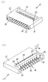
図3はスライダーの斜視図である。図4(A)は2つの接触部を持った第1コンタクトの斜視図であり、(B)は1つの接触部を持った別形態の第1コンタクトの斜視図である。図5はスライダーが閉じた状態の接続部側からみた本発明のコネクタの斜視図である。図6(A)はスライダーが開いた状態の第2コンタクト部分で切断した本発明のコネクタの斜視図であり、(B)はFPCが挿入されスライダーが閉じた状態の第2コンタクト部分で切断した本発明のコネクタの斜視図である。
From Figure 3 with reference to FIG. 6, a description will be given of an embodiment of a connector of the present invention.
FIG. 3 is a perspective view of the slider. FIG. 4A is a perspective view of a first contact having two contact portions, and FIG. 4B is a perspective view of another form of first contact having one contact portion. FIG. 5 is a perspective view of the connector of the present invention as seen from the connecting portion side in a state where the slider is closed. FIG. 6A is a perspective view of the connector of the present invention cut at the second contact portion with the slider opened, and FIG. 6B is cut at the second contact portion with the FPC inserted and the slider closed. It is a perspective view of the connector of the present invention.
本発明のコネクタ101は、主にハウジング121とスライダー161とコンタクト142とを備えている。
The
図に基づいて本発明のコネクタの構成部品について説明する。
まず、本発明のポイントである第1コンタクトについて説明する。このコンタクトは金属製であり、公知技術のプレス加工によって製作されている。前記コンタクトの材質としては、バネ性や導電性などが要求されるので、黄銅やベリリウム銅やリン青銅等を挙げることができる。
The components of the connector of the present invention will be described with reference to the drawings.
First, the first contact which is the point of the present invention will be described. This contact is made of metal and is manufactured by a known press working. The material of the contact is required to be springy or conductive, and examples thereof include brass, beryllium copper, and phosphor bronze.
前記第1コンタクト14は、図4(A)では、略H字形状をしており、主に前記FPC40又は前記FFCと接触する第1接触部22aと、基板に接続する第1接続部24aと、ハウジング121に固定する第1固定部42aと、前記第1接触部22aと前記第1接続部24aとの間に設けられた第1弾性部34a及び第1支点部32aと、前記第1接続部24aと対向する位置に前記第1弾性部34aから延設された第1押受部20aと、前記第1支点部32aから前記第1接触部22aと同じ向きに延設した第1延設部22eとを備え、更に該第1延設部22eの端部に前記FPC40又は前記FFCと接触する第3接触部22cとを備えている。上方側の前記第1接触部22a(図4(A)の図面の上側)と前記第1弾性部34aと前記第1支点部32aと前記第1接続部24aとは、略クランク形状に配置されている。前記第1及び第3接触部22a、22cは、前記FPC40又は前記FFCと接触し易いように凸部形状にしており、前記第1接続部24aは本実施例では図1のように表面実装タイプ(SMT)にしているが、ディップタイプでも良い。即ち、2つの前記第1及び第3接触部22a、22cを設けて、前記FPC40又は前記FFCを挟持するようにする。前記FPC40又は前記FFCの挿入方向に対して、直角方向両側に前記第1及び第3接触部22a、22cを設けることで、前記FPC40又は前記FFCを2つの前記第1及び第3接触部22a、22cで挟持することになり、確実に前記FPC40又は前記FFCと接触できるようになる。
The
前記第1支点部32aと前記第1弾性部34aと前記第1押受部20aとは、前記FPC40又は前記FFCが挿入された際に、次のような作用を果たすための部分である。前記FPC40又は前記FFCが前記ハウジング121の嵌合口18内に挿入された後に、前記スライダー161の前述する軸28周りの回転によって、押圧部36が前記第1コンタクト14の第1接続部24aと第1押受部20aに作用して、前記第1押受部20aが押圧部36の細長形状を利用して押し上げられることで、前記押圧部が前記FPC又は前記FFCを直に押圧することなく、前記スライダーの軸周りの回転に起因して、前記第1接触部22aが前記FPC40又は前記FFC側に押圧される。前記第1支点部32aと前記第1弾性部34aと前記第1押受部20aの大きさや形状は、このような作用を果たすために、適宜設計されている。The
また、前記第1コンタクト14の第1押受部20aの先端に膨れ防止手段を設けることが好ましい。前記スライダー161の前記軸28周りの回転によって、第1押圧部36aを前記第1コンタクト14の第1押受部20aに作用させるとき、前記スライダー161の回転に対する反発力が強い為に、スライダー161の中央部が図6(B)の矢印「ハ」方向に膨れる傾向があるが、前記膨れ防止手段を設けることにより、かかる傾向を防ぐようにすることができるためである。さらに、膨れ防止手段として、前記第1押受部20aの先端に第1突出部26aを設けることが好適である。前記第1突出部26aの大きさは、上記役割を果たすことが出来れば如何なる大きさでもよく、前記スライダー161の第1押圧部36aが引っ掛かる程度に適宜設計する。
Further, Rukoto provided preventing means swelling at the tip of the first
図4(B)に基づいて、別の第1コンタクト141について説明する。ここでは、上述した第1コンタクト14との相違部分についてのみ説明する。別の第1コンタクト141の第1支点部32aから前記第1接触部22aと同じ方向に延設した第1延設部22e、及び前記FPC40又は前記FFCとの第3接触部22cを削除したものであり、形状を略逆h字形状にした。
Another
さらに、本発明の第2のコンタクトについて説明する。第2コンタクト142も金属製であり、公知技術のプレス加工によって製作されている。材質は、第1コンタクト14と同様である。Further, the second contact of the present invention will be described. The
前記第2コンタクト142も第1コンタクト14と同様に略逆h字形状と略H字形状の2つのタイプがあり、略逆h字形状のものは、主にFPC40又はFFCと接触する第2接触部22bと、基板に接続する第2接続部24bと、ハウジング121に固定する第2固定部42bと、前記第2接触部22bと前記第2接続部24bとの間に設けられた第2弾性部34b及び第2支点部32bと前記第2弾性部34bから延設された第2押受部20bとを備えている。前記第2接触部22bと前記第2弾性部34bと前記第2支点部32bと前記第2接続部24bとは、略コ字形状に配置されている。略H字形状のものは、前記第2支点部32bから前記第2押受部20bと同じ向きに延設した第2延設部44が設けられている。前記第2接触部22bは、FPC40又はFFCと接触し易いように凸部形状にしており、前記第2接続部24bは本実施例では図5のように表面実装タイプ(SMT)にしているが、ディップタイプでも良い。Similarly to the
前記第2支点部32bと前記第2弾性部34bと前記第2押受部20bとは、前記第1コンタクト14と同様に、前記FPC40又は前記FFCが挿入された際に、前記スライダー1611の軸周りの回転に伴い、第2押圧部36bが前記第2コンタクト142の第2押受部20bに作用して、前記第2押受部20bが押圧部36の細長形状を利用して押し上げられることで、前記押圧部が前記FPC又は前記FFCを直に押圧することなく、前記スライダーの軸周りの回転に起因して、前記第2接触部22bが前記FPC40又は前記FFC側に押圧される。前記第2支点部32bと前記第2弾性部34bと前記第2押受部20bの大きさや形状は、このような作用を果たすために、適宜設計されている。
The
また、前記第2コンタクト142の第2押受部20bの先端に第2突出部26bを設ける。前記スライダー161の軸周りの回転に伴い、押圧部36を前記第2コンタクト142の第2押受部20bに作用させるとき、前記スライダー161の回転に対する反発力が強い為に、スライダー161の中央部が図6(B)の矢印「ハ」方向に膨れる傾向があるが、前記第2突出部26bを設けることにより、かかる傾向を防ぐようにすることができる。前記第2突出部26bの大きさは、このような役割を果たすことが出来れば如何なる大きさでもよく、前記スライダー161の押圧部36が引っ掛かる程度に適宜設計する。In addition, a second protrusion 26b is provided at the tip of the second
次に、本発明のもう一つのポイントであるスライダーについて説明する。このスライダーは電気絶縁性のプラスチックであり、公知技術の射出成形によって製作され、この材質としては寸法安定性や加工性やコスト等を考慮して適宜選択するが、一般的にはポリブチレンテレフタレート(PBT)やポリアミド(66PA、46PA)や液晶ポリマー(LCP)やポリカーボネート(PC)やこれらの合成材料を挙げることができる。該スライダー161は、主に前記ハウジング121の嵌合口18とは反対側に回転可能に装着される軸28部分と、前記第1及び第2コンタクト14、142の第1及び第2押受部20a、20bを押圧する押圧部36と、前記第1及び第2コンタクト14、142の第1及び第2突出部26a、26bが係合する係止孔30とを備えている。前記軸28は、前記スライダー161を回転させるための支点であり、前記ハウジング121の長手方向両側に前記スライダー161が回転可能に適宜装着されている。また、長手方向両側には、前記第1及び第2コンタクト14、142の第1及び第2押受部20a、20bを押圧した際にスライダー161が高さ(図面の上)方向に持ち上がらないようにするために前記ハウジング121と係合するロック部が設けられている。ロック部の形状や大きさ等は、ハウジング121に係合できれば如何なるものでもよく、上述の役割やコネクタの大きさや強度等を考慮して適宜設計する。
Next, the slider which is another point of the present invention will be described. This slider is an electrically insulating plastic and is manufactured by a known technique of injection molding. The material is appropriately selected in consideration of dimensional stability, workability, cost, etc. In general, polybutylene terephthalate ( PBT), polyamide (66PA, 46PA), liquid crystal polymer (LCP), polycarbonate (PC), and synthetic materials thereof. The
前記押圧部36は、前記第1及び第2コンタクト14、142の第1及び第2押受部20a、20bに押し付ける部分であり、その形状としては細長形状にする。前記押圧部36の形状は、本実施例では楕円形状をしている。このように楕円形状にすることによって、図2(A)のように前記スライダー161を矢印「イ」方向に回転させ、前記第1コンタクト14の第1押受部20a及び前記第2コンタクト142の第2押受部20bに作用して、前記押圧部36の大きさの変化により前記第1及び第2コンタクト14、142の第1及び第2押受部20a、20bが持ち上げられ、前記FPC40又は前記FFCを前記第1及び第2コンタクト14、142の第1及び第2接触部22a、22b側に押し付けている。前記押圧部36の形状としては、前記スライダー161の軸周りの回転に伴い、前記第1コンタクト14の第1押受部20aと前記第2コンタクト142の第2押受部20bに作用して、長軸と短軸といった大きさの違いにより前記第1及び第2コンタクト14、142の第1及び第2押受部20a、20bを押し上げられれば、如何なるものでもよい。
The
また、前記スライダー161を回転した際に、前記スライダー161の回転に対する反発力が強く、前記スライダー161の中央部が図6(B)の矢印「ハ」方向に膨れてしまうことを防ぐようにする為に、前記第2コンタクト142の第2突出部26bが係合する前記係止孔30が別個独立に設けられている。前記係止孔30を別個独立に設けることで、前記スライダー161の強度アップや回転時の変形を防止している。
Further, upon rotating the
最後に、ハウジングについて説明する。このハウジングは電気絶縁性のプラスチックであり、公知技術の射出成形によって製作され、この材質としては寸法安定性や加工性やコスト等を考慮して適宜選択するが、一般的にはポリブチレンテレフタレート(PBT)やポリアミド(66PA、46PA)や液晶ポリマー(LCP)やポリカーボネート(PC)やこれらの合成材料を挙げることができる。前記ハウジング121には、所要数の前記第1及び第2コンタクト14、141、142が装着される挿入溝38が設けられており、圧入や引っ掛け(ランス)や溶着等によって固定されている。
Finally, the housing will be described. This housing is an electrically insulating plastic, and is manufactured by injection molding of a known technique. The material is appropriately selected in consideration of dimensional stability, workability, cost, etc. In general, polybutylene terephthalate ( PBT), polyamide (66PA, 46PA), liquid crystal polymer (LCP), polycarbonate (PC), and synthetic materials thereof. The
また、長手方向両側には、前記スライダー161の軸28が回転可能に装着される軸受部が設けられている。この軸受部の形状や大きさは、前記スライダー161の軸28が回転できるように装着されていれば如何なるものでもよく、この役割や前記ハウジング121の強度や大きさ等を考慮して適宜設計する。なお、長手方向両側には、前記スライダー161のロック部に対応した位置に係止部が設けられている。
Further, bearing portions to which the
本発明は、携帯電話やノートパソコンやデジタルカメラ等に使用されるコネクタに活用され、特にフレキシブルプリント基板(以下「FPC」という)やフレキシブルフラットケーブル(以下「FFC」という)にコンタクトを押しつける機構に関するものである。The present invention is used for a connector used in a mobile phone, a notebook computer, a digital camera, and the like, and particularly relates to a mechanism for pressing a contact against a flexible printed circuit board (hereinafter referred to as “FPC”) or a flexible flat cable (hereinafter referred to as “FFC”). Is.
10、101、60 コネクタ
12、121、62 ハウジング
14、141 第1コンタクト
142 第2コンタクト
16、161、66 スライダー
18 嵌合口
20a、20b 第1及び第2押受部
22a〜22d 第1〜第4接触部
24a、24b 第1及び第2接続部
26a、26b 第1及び第2突出部
28 軸
30 係止孔
32a、32b 第1及び第2支点部
34a、34b 第1及び第2弾性部
36、68 押圧部
38 挿入溝
40 FPC
42a、42b 第1及び第2固定部
44 第2延設部
70 受け部
72 スリット
74 装着部
76 固定具
10, 101, 60
14, 141 first contact
142 2nd contact
16, 161, 66
20a, 20b first and second pressing portions
22a-22d 1st-4th contact part
24a, 24b first and second connection parts
26a, 26b first and second projecting
32a, 32b first and second fulcrum parts
34a, 34b First and second
42a, 42b First and second fixing
Claims (11)
前記FPC又は前記FFCと接触する接触部、及び基板に接続する接続部を有する所要数のコンタクトと、該コンタクトが保持されるとともに前記FPC又は前記FFCが挿入される嵌合口を有するハウジングと、前記嵌合口の反対側に、前記FPC又は前記FFCに前記コンタクトを押圧するスライダーとを備え、前記接触部が、前記FPC又は前記FFCの少なくとも上面と接触するコネクタにおいて、A required number of contacts having a contact portion that contacts the FPC or the FFC, and a connection portion that connects to a substrate; a housing having a fitting port in which the contact is held and the FPC or the FFC is inserted; On the opposite side of the fitting port, the FPC or FFC is provided with a slider that presses the contact, and the contact portion contacts at least the upper surface of the FPC or the FFC.
前記コンタクトは、2種類の異なるコンタクトである第1及び第2コンタクトを備え、これら第1及び第2コンタクトは、ハウジングへの挿入方向を互い違いに変えて千鳥に配置され、The contact includes first and second contacts which are two different types of contacts, and the first and second contacts are arranged in a staggered manner by alternately changing the direction of insertion into the housing.
前記ハウジングには、前記スライダーが装着される側から嵌合口側に向かう方向に延びる第1挿入溝と、嵌合口側から前記スライダーが装着される側に向かう方向に延びる第2挿入溝が設けられ、前記第1コンタクトは前記第1挿入溝に挿入され、前記第2コンタクトは前記第2挿入溝に挿入され、The housing is provided with a first insertion groove extending in a direction from the side where the slider is mounted toward the fitting port and a second insertion groove extending in a direction from the fitting port toward the side where the slider is mounted. The first contact is inserted into the first insertion groove, the second contact is inserted into the second insertion groove,
前記第1コンタクトには、前記FPC又は前記FFCの上面側に位置しかつ前記接触部である第1接触部と、前記接続部である第1接続部との間に、第1弾性部と第1支点部とを設けるとともに、前記第1接触部と前記第1弾性部と前記第1支点部と前記第1接続部とを、前記第1支点部が前記第1弾性部の下端側に位置するよう略クランク形状に配置し、かつ、前記第1接続部と対向する位置に前記第1弾性部から延設された第1押受部を設けるとともに、少なくとも前記スライダーの押圧部が接する、前記第1押受部の下面、及び該第1押受部に対向する前記第1接続部の上面をともにフラットに形成し、The first contact is located between the first contact portion that is located on the upper surface side of the FPC or the FFC and is the contact portion, and the first connection portion that is the connection portion. A first fulcrum portion, and the first contact portion, the first elastic portion, the first fulcrum portion, and the first connection portion, and the first fulcrum portion is located on a lower end side of the first elastic portion. The first pressing portion extending from the first elastic portion is provided at a position facing the first connecting portion, and at least the pressing portion of the slider is in contact with the first connecting portion. Both the lower surface of the first pressing portion and the upper surface of the first connection portion facing the first pressing portion are formed flat,
前記第2コンタクトには、前記FPC又は前記FFCの上面側に位置しかつ前記接触部である第2接触部と、前記接続部である第2接続部との間に、第2弾性部と第2支点部とを設けるとともに、前記第2接触部と前記第2弾性部と前記第2支点部と前記第2接続部とを、前記第2支点部が前記第2弾性部の下端側に位置するよう略コ字状に配置し、かつ、前記第2弾性部から前記第2接触部と反対方向に延設された第2押受部を設けるとともに、少なくとも前記スライダーの押圧部が接する前記第2押受部の下面をフラットに形成し、The second contact is located between the second contact portion that is located on the upper surface side of the FPC or the FFC and that is the contact portion, and the second connection portion that is the connection portion. The second fulcrum portion is provided, and the second contact portion, the second elastic portion, the second fulcrum portion, and the second connection portion are arranged, and the second fulcrum portion is positioned on the lower end side of the second elastic portion. A second pressing portion that is arranged in a substantially U-shape and extends from the second elastic portion in a direction opposite to the second contact portion, and at least the pressing portion of the slider is in contact with the second pressing portion. 2 Form the bottom surface of the holding part flat,
前記スライダーには、長手方向に連設した細長形状の押圧部を前記第1及び第2押受部の直下に設けるとともに、所要数の前記第1及び第2コンタクトの第1及び第2押受部の先端と係合する係止孔を別個独立に形成して、隣接するコンタクト間に仕切り壁を配設し、The slider is provided with an elongate pressing portion continuously provided in the longitudinal direction, immediately below the first and second pressing portions, and the first and second pressing portions of the required number of the first and second contacts. A locking hole that engages with the tip of the part is formed independently and a partition wall is disposed between adjacent contacts,
前記スライダーの軸周りの回転に伴い、前記押圧部が前記第1及び第2コンタクトの第1及び第2押受部に作用して、前記第1押受部及び前記第2押受部が前記押圧部の細長形状を利用して押し上げられ、前記押圧部が前記FPC又は前記FFCを直に押圧することなく、前記スライダーの軸周りの回転に起因して前記第1及び第2接触部が前記FPC又は前記FFCを押圧し、これにより電気接続されることを特徴とするコネクタ。As the slider rotates about the axis, the pressing portion acts on the first and second pressing portions of the first and second contacts, and the first pressing portion and the second pressing portion are The first and second contact portions are pushed up by utilizing the elongated shape of the pressing portion, and the first and second contact portions do not directly press the FPC or the FFC, and the first and second contact portions are caused by the rotation around the axis of the slider. A connector, wherein the FPC or the FFC is pressed to be electrically connected.
前記FPC又は前記FFCと接触する接触部、及び基板に接続する接続部を有する所要数のコンタクトと、該コンタクトが保持されるとともに前記FPC又は前記FFCが挿入される嵌合口を有するハウジングと、前記嵌合口の反対側に、前記FPC又は前記FFCに前記コンタクトを押圧するスライダーとを備え、前記接触部が、前記FPC又は前記FFCの少なくとも上面と接触するコネクタにおいて、A required number of contacts having a contact portion that contacts the FPC or the FFC, and a connection portion that connects to a substrate; a housing having a fitting port in which the contact is held and the FPC or the FFC is inserted; On the opposite side of the fitting port, the FPC or FFC is provided with a slider that presses the contact, and the contact portion contacts at least the upper surface of the FPC or the FFC.
前記コンタクトは、2種類の異なるコンタクトである第1及び第2コンタクトを備え、これら第1及び第2コンタクトは、ハウジングへの挿入方向を互い違いに変えて千鳥に配置され、The contact includes first and second contacts which are two different types of contacts, and the first and second contacts are arranged in a staggered manner by alternately changing the direction of insertion into the housing.
前記ハウジングには、前記スライダーが装着される側から嵌合口側に向かう方向に延びる第1挿入溝と、嵌合口側から前記スライダーが装着される側に向かう方向に延びる第2挿入溝が設けられ、前記第1コンタクトは前記第1挿入溝に挿入され、前記第2コンタクトは前記第2挿入溝に挿入され、The housing is provided with a first insertion groove extending in a direction from the side where the slider is mounted toward the fitting port and a second insertion groove extending in a direction from the fitting port toward the side where the slider is mounted. The first contact is inserted into the first insertion groove, the second contact is inserted into the second insertion groove,
前記第1コンタクトには、前記FPC又は前記FFCの上面側に位置しかつ前記接触部である第1接触部と、前記接続部である第1接続部との間に、第1弾性部と第1支点部とを設けるとともに、前記第1接触部と前記第1弾性部と前記第1支点部と前記第1接続部とを、前記第1支点部が前記第1弾性部の下端側に位置するよう略クランク形状に配置し、かつ、前記第1接続部と対向する位置に前記第1弾性部から延設された第1押受部を設けるとともに前記第1支点部から前記第1接触部と同じ方向に延設した第1延設部を有し、前記第1延設部は、該第1延設部と前記第1接触部との間にハウジングが存在しない状態で前記第1挿入溝に挿入され、The first contact is located between the first contact portion that is located on the upper surface side of the FPC or the FFC and is the contact portion, and the first connection portion that is the connection portion. A first fulcrum portion, and the first contact portion, the first elastic portion, the first fulcrum portion, and the first connection portion, and the first fulcrum portion is located on a lower end side of the first elastic portion. The first contact portion is provided in a substantially crank shape so as to extend from the first elastic portion at a position facing the first connection portion and from the first fulcrum portion to the first contact portion. The first extending portion extends in the same direction as the first extending portion, and the first extending portion has the first insertion portion without a housing between the first extending portion and the first contact portion. Inserted into the groove,
前記第2コンタクトには、前記FPC又は前記FFCの上面側に位置しかつ前記接触部である第2接触部と、前記接続部である第2接続部との間に、第2弾性部と第2支点部とを設けるとともに、前記第2接触部と前記第2弾性部と前記第2支点部と前記第2接続部とを、前記第2支点部が前記第2弾性部の下端側に位置するよう略コ字状に配置し、かつ、前記第2弾性部から前記第2接触部と反対方向に延設された第2押受部を設け、The second contact is located between the second contact portion that is located on the upper surface side of the FPC or the FFC and that is the contact portion, and the second connection portion that is the connection portion. The second fulcrum portion is provided, and the second contact portion, the second elastic portion, the second fulcrum portion, and the second connection portion are arranged, and the second fulcrum portion is positioned on the lower end side of the second elastic portion. A second pressing portion that is arranged in a substantially U-shape and extends from the second elastic portion in a direction opposite to the second contact portion,
前記スライダーには、長手方向に連設した細長形状の押圧部を前記第1及び第2押受部の直下に設けるとともに、所要数の前記第1及び第2コンタクトの第1及び第2押受部の先端と係合する係止孔を別個独立に形成して、隣接するコンタクト間に仕切り壁を配設し、The slider is provided with an elongate pressing portion continuously provided in the longitudinal direction, immediately below the first and second pressing portions, and the first and second pressing portions of the required number of the first and second contacts. A locking hole that engages with the tip of the part is formed independently and a partition wall is disposed between adjacent contacts,
前記スライダーの軸周りの回転に伴い、前記押圧部が前記第1及び第2コンタクトの第1及び第2押受部に作用して、前記第1押受部及び前記第2押受部が前記押圧部の細長形状を利用して押し上げられ、前記押圧部が前記FPC又は前記FFCを直に押圧することなく、前記スライダーの軸周りの回転に起因して前記第1及び第2接触部が前記FPC又は前記FFCを押圧し、これにより電気接続されることを特徴とするコネクタ。As the slider rotates about the axis, the pressing portion acts on the first and second pressing portions of the first and second contacts, and the first pressing portion and the second pressing portion are The first and second contact portions are pushed up by utilizing the elongated shape of the pressing portion, and the first and second contact portions do not directly press the FPC or the FFC, and the first and second contact portions are caused by the rotation around the axis of the slider. A connector, wherein the FPC or the FFC is pressed to be electrically connected.
前記FPC又は前記FFCと接触する接触部、及び基板に接続する接続部を有する所要数のコンタクトと、該コンタクトが保持されるとともに前記FPC又は前記FFCが挿入される嵌合口を有するハウジングと、前記嵌合口の反対側に、前記FPC又は前記FFCに前記コンタクトを押圧するスライダーとを備え、前記接触部が、前記FPC又は前記FFCの少なくとも上面と接触するコネクタにおいて、A required number of contacts having a contact portion that contacts the FPC or the FFC, and a connection portion that connects to a substrate; a housing having a fitting port in which the contact is held and the FPC or the FFC is inserted; On the opposite side of the fitting port, the FPC or FFC is provided with a slider that presses the contact, and the contact portion contacts at least the upper surface of the FPC or the FFC.
前記コンタクトは、2種類の異なるコンタクトである第1及び第2コンタクトを備え、これら第1及び第2コンタクトは、ハウジングへの挿入方向を互い違いに変えて千鳥に配置され、The contact includes first and second contacts which are two different types of contacts, and the first and second contacts are arranged in a staggered manner by alternately changing the direction of insertion into the housing.
前記ハウジングには、前記スライダーが装着される側から嵌合口側に向かう方向に延びる第1挿入溝と、嵌合口側から前記スライダーが装着される側に向かう方向に延びる第2挿入溝が設けられ、前記第1コンタクトは前記第1挿入溝に挿入され、前記第2コンタクトは前記第2挿入溝に挿入され、The housing is provided with a first insertion groove extending in a direction from the side where the slider is mounted toward the fitting port and a second insertion groove extending in a direction from the fitting port toward the side where the slider is mounted. The first contact is inserted into the first insertion groove, the second contact is inserted into the second insertion groove,
前記第1コンタクトには、前記FPC又は前記FFCの上面側に位置しかつ前記接触部である第1接触部と、前記接続部である第1接続部との間に、第1弾性部と第1支点部とを設けるとともに、前記第1接触部と前記第1弾性部と前記第1支点部と前記第1接続部とを、前記第1支点部が前記第1弾性部の下端側に位置するよう略クランク形状に配置し、かつ、前記第1接続部と対向する位置に前記第1弾性部から延設された第1押受部を設けるとともに前記第1支点部から前記第1接触部と同じ方向に延設した第1延設部を有し、前記第1延設部は、該第1延設部と前記第1接触部との間にハウジングが存在しない状態で前記第1挿入溝に挿入され、少なくとも前記スライダーの押圧部が接する、前記第1押受部の下面、及び該第1押受部に対向する前記第1接続部の上面をともにフラットに形成し、The first contact is located between the first contact portion that is located on the upper surface side of the FPC or the FFC and is the contact portion, and the first connection portion that is the connection portion. A first fulcrum portion, and the first contact portion, the first elastic portion, the first fulcrum portion, and the first connection portion, and the first fulcrum portion is located on a lower end side of the first elastic portion. The first contact portion is provided in a substantially crank shape so as to extend from the first elastic portion at a position facing the first connection portion and from the first fulcrum portion to the first contact portion. The first extending portion extends in the same direction as the first extending portion, and the first extending portion has the first insertion portion without a housing between the first extending portion and the first contact portion. A lower surface of the first pressing portion, which is inserted into the groove and is in contact with at least the pressing portion of the slider, and the first pressing portion Together form a flat upper surface of the first connecting portion opposed to,
前記第2コンタクトには、前記FPC又は前記FFCの上面側に位置しかつ前記接触部である第2接触部と、前記接続部である第2接続部との間に、第2弾性部と第2支点部とを設けるとともに、前記第2接触部と前記第2弾性部と前記第2支点部と前記第2接続部とを、前記第2支点部が前記第2弾性部の下端側に位置するよう略コ字状に配置し、かつ、前記第2弾性部から前記第2接触部と反対方向に延設された第2押受部を設け、少なくとも前記スライダーの押圧部が接する前記第2押受部の下面をフラットに形成し、The second contact is located between the second contact portion that is located on the upper surface side of the FPC or the FFC and that is the contact portion, and the second connection portion that is the connection portion. The second fulcrum portion is provided, and the second contact portion, the second elastic portion, the second fulcrum portion, and the second connection portion are arranged, and the second fulcrum portion is positioned on the lower end side of the second elastic portion. The second pressing portion is disposed in a substantially U-shape and extends from the second elastic portion in a direction opposite to the second contact portion, and at least the second pressing portion of the slider is in contact with the second pressing portion. The bottom surface of the holding part is formed flat,
前記スライダーには、長手方向に連設した細長形状の押圧部を前記第1及び第2押受部の直下に設けるとともに、所要数の前記第1及び第2コンタクトの第1及び第2押受部の先端と係合する係止孔を別個独立に形成して、隣接するコンタクト間に仕切り壁を配設し、The slider is provided with an elongate pressing portion continuously provided in the longitudinal direction, immediately below the first and second pressing portions, and the first and second pressing portions of the required number of the first and second contacts. A locking hole that engages with the tip of the part is formed independently and a partition wall is disposed between adjacent contacts,
前記スライダーの軸周りの回転に伴い、前記押圧部が前記第1及び第2コンタクトの第1及び第2押受部に作用して、前記第1押受部及び前記第2押受部が前記押圧部の細長形状を利用して押し上げられ、前記押圧部が前記FPC又は前記FFCを直に押圧することなく、前記スライダーの軸周りの回転に起因して前記第1及び第2接触部が前記FPC又は前記FFCを押圧し、これにより電気接続されることを特徴とするコネクタ。As the slider rotates about the axis, the pressing portion acts on the first and second pressing portions of the first and second contacts, and the first pressing portion and the second pressing portion are The first and second contact portions are pushed up by utilizing the elongated shape of the pressing portion, and the first and second contact portions do not directly press the FPC or the FFC, and the first and second contact portions are caused by the rotation around the axis of the slider. A connector, wherein the FPC or the FFC is pressed to be electrically connected.
前記FPC又は前記FFCと接触する接触部、及び基板に接続する接続部を有する所要数のコンタクトと、該コンタクトが保持されるとともに前記FPC又は前記FFCが挿入される嵌合口を有するハウジングと、前記嵌合口の反対側に、前記FPC又は前記FFCに前記コンタクトを押圧するスライダーとを備え、前記接触部が、前記FPC又は前記FFCの少なくとも上面と接触するコネクタにおいて、A required number of contacts having a contact portion that contacts the FPC or the FFC, and a connection portion that connects to a substrate; a housing having a fitting port in which the contact is held and the FPC or the FFC is inserted; On the opposite side of the fitting port, the FPC or FFC is provided with a slider that presses the contact, and the contact portion contacts at least the upper surface of the FPC or the FFC.
前記コンタクトは、前記FPC又は前記FFCの上面側に位置しかつ前記接触部である第2接触部と、前記接続部である第2接続部との間に、第2弾性部と第2支点部とを有するとともに、前記第2接触部と前記第2弾性部と前記第2支点部と前記第2接続部とを、前記第2支点部が前記第2弾性部の下端側に位置するよう略コ字状に配置し、かつ、前記第2弾性部から前記第2接触部と反対方向に延設された第2押受部を有するとともに、少なくとも前記スライダーの押圧部が接する前記第2押受部の下面をフラットに形成してなる第2コンタクトを含み、The contact is located on the upper surface side of the FPC or the FFC, and between the second contact portion that is the contact portion and the second connection portion that is the connection portion, a second elastic portion and a second fulcrum portion And the second contact portion, the second elastic portion, the second fulcrum portion, and the second connection portion are arranged so that the second fulcrum portion is positioned on the lower end side of the second elastic portion. The second pressing member that has a U-shaped second pressing portion that extends from the second elastic portion in a direction opposite to the second contact portion, and that is in contact with at least the pressing portion of the slider. Including a second contact formed by flatly forming the lower surface of the portion,
前記ハウジングには、嵌合口側から前記スライダーが装着される側に向かう方向に延びる第2挿入溝が設けられ、前記第2コンタクトは前記第2挿入溝に挿入され、The housing is provided with a second insertion groove extending in a direction from the fitting port side toward the side on which the slider is mounted, and the second contact is inserted into the second insertion groove,
前記スライダーには、長手方向に連設した細長形状の押圧部を前記第2押受部の直下に設けるとともに、所要数の前記第2コンタクトの第2押受部の先端と係合する係止孔を別個独立に形成して、隣接するコンタクト間に仕切り壁を配設し、The slider is provided with an elongate pressing portion continuously provided in the longitudinal direction, immediately below the second pressing portion, and engaging with the tip of the second pressing portion of the required number of the second contacts. Forming the holes separately and arranging partition walls between adjacent contacts;
前記スライダーの軸周りの回転に伴い、前記押圧部が前記第2コンタクトの第2押受部に作用して、前記第2押受部が前記押圧部の細長形状を利用して押し上げられ、前記押圧部が前記FPC又は前記FFCを直に押圧することなく、前記スライダーの軸周りの回転に起因して前記第2接触部が前記FPC又は前記FFCを押圧し、これにより電気接続されることを特徴とするコネクタ。With the rotation around the axis of the slider, the pressing portion acts on the second pressing portion of the second contact, and the second pressing portion is pushed up using the elongated shape of the pressing portion, Without the pressing part directly pressing the FPC or the FFC, the second contact part presses the FPC or the FFC due to the rotation around the axis of the slider, and is thereby electrically connected. Characteristic connector.
Priority Applications (1)
| Application Number | Priority Date | Filing Date | Title |
|---|---|---|---|
| JP2012152142A JP5203526B2 (en) | 2012-07-06 | 2012-07-06 | connector |
Applications Claiming Priority (1)
| Application Number | Priority Date | Filing Date | Title |
|---|---|---|---|
| JP2012152142A JP5203526B2 (en) | 2012-07-06 | 2012-07-06 | connector |
Related Parent Applications (1)
| Application Number | Title | Priority Date | Filing Date |
|---|---|---|---|
| JP2012068883A Division JP5057537B2 (en) | 2012-03-26 | 2012-03-26 | connector |
Related Child Applications (1)
| Application Number | Title | Priority Date | Filing Date |
|---|---|---|---|
| JP2012245873A Division JP2013051211A (en) | 2012-11-08 | 2012-11-08 | Connector |
Publications (3)
| Publication Number | Publication Date |
|---|---|
| JP2012212688A JP2012212688A (en) | 2012-11-01 |
| JP2012212688A5 JP2012212688A5 (en) | 2012-12-27 |
| JP5203526B2 true JP5203526B2 (en) | 2013-06-05 |
Family
ID=47266447
Family Applications (1)
| Application Number | Title | Priority Date | Filing Date |
|---|---|---|---|
| JP2012152142A Expired - Lifetime JP5203526B2 (en) | 2012-07-06 | 2012-07-06 | connector |
Country Status (1)
| Country | Link |
|---|---|
| JP (1) | JP5203526B2 (en) |
Family Cites Families (8)
| Publication number | Priority date | Publication date | Assignee | Title |
|---|---|---|---|---|
| JPH03103578U (en) * | 1990-02-09 | 1991-10-28 | ||
| JP2584146Y2 (en) * | 1992-04-15 | 1998-10-30 | ミツミ電機株式会社 | Electrical connector |
| JP3101951B2 (en) * | 1997-01-24 | 2000-10-23 | 日本電気株式会社 | Low insertion / extraction force connector |
| JP3047862B2 (en) * | 1997-07-08 | 2000-06-05 | オムロン株式会社 | connector |
| JP3932521B2 (en) * | 1998-04-17 | 2007-06-20 | Smk株式会社 | Printed circuit board connector |
| JP3295808B2 (en) * | 1999-10-06 | 2002-06-24 | 日本航空電子工業株式会社 | Cable connector |
| JP2002050423A (en) * | 2000-08-02 | 2002-02-15 | Smk Corp | Connector for flexible base board connection |
| JP2002190360A (en) * | 2000-12-20 | 2002-07-05 | Smk Corp | Printed circuit board connector |
-
2012
- 2012-07-06 JP JP2012152142A patent/JP5203526B2/en not_active Expired - Lifetime
Also Published As
| Publication number | Publication date |
|---|---|
| JP2012212688A (en) | 2012-11-01 |
Similar Documents
| Publication | Publication Date | Title |
|---|---|---|
| JP5024912B2 (en) | connector | |
| JP5203526B2 (en) | connector | |
| JP5057537B2 (en) | connector | |
| JP6817490B2 (en) | connector | |
| JP6440236B6 (en) | connector | |
| JP6514822B2 (en) | connector | |
| JP6514823B2 (en) | connector | |
| JP6542491B2 (en) | connector | |
| JP5770352B1 (en) | connector | |
| JP5770352B6 (en) | connector | |
| JP2012018934A5 (en) | ||
| JP5700889B1 (en) | connector | |
| JP5577444B2 (en) | connector | |
| JP5700889B6 (en) | connector | |
| JP4993529B2 (en) | connector | |
| JP2012212688A5 (en) | ||
| JP6087012B2 (en) | connector | |
| JP6087012B6 (en) | connector | |
| JP6161777B1 (en) | connector | |
| JP6161777B6 (en) | connector | |
| JP5946577B2 (en) | connector | |
| JP5946577B6 (en) | connector | |
| JP5704776B1 (en) | connector | |
| JP4768873B2 (en) | connector | |
| JP5704776B6 (en) | connector |
Legal Events
| Date | Code | Title | Description |
|---|---|---|---|
| A621 | Written request for application examination |
Free format text: JAPANESE INTERMEDIATE CODE: A621 Effective date: 20120803 |
|
| RD03 | Notification of appointment of power of attorney |
Free format text: JAPANESE INTERMEDIATE CODE: A7423 Effective date: 20121022 |
|
| A521 | Request for written amendment filed |
Free format text: JAPANESE INTERMEDIATE CODE: A523 Effective date: 20121108 |
|
| A871 | Explanation of circumstances concerning accelerated examination |
Free format text: JAPANESE INTERMEDIATE CODE: A871 Effective date: 20121112 |
|
| A975 | Report on accelerated examination |
Free format text: JAPANESE INTERMEDIATE CODE: A971005 Effective date: 20121122 |
|
| TRDD | Decision of grant or rejection written | ||
| A01 | Written decision to grant a patent or to grant a registration (utility model) |
Free format text: JAPANESE INTERMEDIATE CODE: A01 Effective date: 20130201 |
|
| A61 | First payment of annual fees (during grant procedure) |
Free format text: JAPANESE INTERMEDIATE CODE: A61 Effective date: 20130213 |
|
| R150 | Certificate of patent or registration of utility model |
Ref document number: 5203526 Country of ref document: JP Free format text: JAPANESE INTERMEDIATE CODE: R150 Free format text: JAPANESE INTERMEDIATE CODE: R150 |
|
| FPAY | Renewal fee payment (event date is renewal date of database) |
Free format text: PAYMENT UNTIL: 20160222 Year of fee payment: 3 |
|
| R250 | Receipt of annual fees |
Free format text: JAPANESE INTERMEDIATE CODE: R250 |
|
| R250 | Receipt of annual fees |
Free format text: JAPANESE INTERMEDIATE CODE: R250 |
|
| R250 | Receipt of annual fees |
Free format text: JAPANESE INTERMEDIATE CODE: R250 |
|
| R250 | Receipt of annual fees |
Free format text: JAPANESE INTERMEDIATE CODE: R250 |
|
| R250 | Receipt of annual fees |
Free format text: JAPANESE INTERMEDIATE CODE: R250 |
|
| R250 | Receipt of annual fees |
Free format text: JAPANESE INTERMEDIATE CODE: R250 |
|
| R250 | Receipt of annual fees |
Free format text: JAPANESE INTERMEDIATE CODE: R250 |
|
| EXPY | Cancellation because of completion of term |