JP5203003B2 - Device for correcting the display mechanism of a watch and gears suitable for the device - Google Patents
Device for correcting the display mechanism of a watch and gears suitable for the device Download PDFInfo
- Publication number
- JP5203003B2 JP5203003B2 JP2008079830A JP2008079830A JP5203003B2 JP 5203003 B2 JP5203003 B2 JP 5203003B2 JP 2008079830 A JP2008079830 A JP 2008079830A JP 2008079830 A JP2008079830 A JP 2008079830A JP 5203003 B2 JP5203003 B2 JP 5203003B2
- Authority
- JP
- Japan
- Prior art keywords
- teeth
- tooth
- pitch
- diameter
- correction
- Prior art date
- Legal status (The legal status is an assumption and is not a legal conclusion. Google has not performed a legal analysis and makes no representation as to the accuracy of the status listed.)
- Active
Links
- 230000007246 mechanism Effects 0.000 title claims abstract description 14
- 238000004804 winding Methods 0.000 claims description 20
- 230000008878 coupling Effects 0.000 abstract description 4
- 238000010168 coupling process Methods 0.000 abstract description 4
- 238000005859 coupling reaction Methods 0.000 abstract description 4
- 230000004048 modification Effects 0.000 description 3
- 238000012986 modification Methods 0.000 description 3
- 230000007935 neutral effect Effects 0.000 description 3
- 238000000605 extraction Methods 0.000 description 2
- 230000000295 complement effect Effects 0.000 description 1
- 239000000470 constituent Substances 0.000 description 1
Images


Classifications
-
- G—PHYSICS
- G04—HOROLOGY
- G04B—MECHANICALLY-DRIVEN CLOCKS OR WATCHES; MECHANICAL PARTS OF CLOCKS OR WATCHES IN GENERAL; TIME PIECES USING THE POSITION OF THE SUN, MOON OR STARS
- G04B19/00—Indicating the time by visual means
- G04B19/24—Clocks or watches with date or week-day indicators, i.e. calendar clocks or watches; Clockwork calendars
- G04B19/243—Clocks or watches with date or week-day indicators, i.e. calendar clocks or watches; Clockwork calendars characterised by the shape of the date indicator
- G04B19/247—Clocks or watches with date or week-day indicators, i.e. calendar clocks or watches; Clockwork calendars characterised by the shape of the date indicator disc-shaped
- G04B19/25—Devices for setting the date indicators manually
-
- G—PHYSICS
- G04—HOROLOGY
- G04B—MECHANICALLY-DRIVEN CLOCKS OR WATCHES; MECHANICAL PARTS OF CLOCKS OR WATCHES IN GENERAL; TIME PIECES USING THE POSITION OF THE SUN, MOON OR STARS
- G04B13/00—Gearwork
- G04B13/02—Wheels; Pinions; Spindles; Pivots
- G04B13/027—Wheels; Pinions; Spindles; Pivots planar toothing: shape and design
-
- Y—GENERAL TAGGING OF NEW TECHNOLOGICAL DEVELOPMENTS; GENERAL TAGGING OF CROSS-SECTIONAL TECHNOLOGIES SPANNING OVER SEVERAL SECTIONS OF THE IPC; TECHNICAL SUBJECTS COVERED BY FORMER USPC CROSS-REFERENCE ART COLLECTIONS [XRACs] AND DIGESTS
- Y10—TECHNICAL SUBJECTS COVERED BY FORMER USPC
- Y10T—TECHNICAL SUBJECTS COVERED BY FORMER US CLASSIFICATION
- Y10T74/00—Machine element or mechanism
- Y10T74/19—Gearing
- Y10T74/1987—Rotary bodies
Landscapes
- Physics & Mathematics (AREA)
- General Physics & Mathematics (AREA)
- Electromechanical Clocks (AREA)
- Gears, Cams (AREA)
- Electric Clocks (AREA)
Abstract
Description
本発明は、時計に関し、特に時計の時間(本明細書において時間とは、日にち、月、曜日のいずれかを意味する)表示機構の修正装置に関する。この修正装置は、同一面に配置された2個の歯群に適合する歯車を有する。本発明はこの歯車にも関する。 The present invention relates to a timepiece, and more particularly to an apparatus for correcting a time of a timepiece (in the present specification, time means any of date, month, and day of the week). This correction device has a gear that fits two teeth arranged in the same plane. The invention also relates to this gear.
時間表示(日付)機構は当業者に公知である。この機構は、日付リングのような表示部材と、この表示部材を駆動する機構と、巻き上げステム(軸、竜頭)により駆動される修正装置とを有する。この修正装置は複雑かつ取り扱いが困難である。この修正装置は、巻き上げステムに搭載されたピニオンで駆動される少なくとも1個の中間歯車と、前記中間歯車と表示部材と噛み合う、スライドするあるいは一定位置を保つ修正ピニオンとを有する。 Time display (date) mechanisms are known to those skilled in the art. This mechanism includes a display member such as a date ring, a mechanism for driving the display member, and a correction device driven by a winding stem (shaft, crown). This correction device is complex and difficult to handle. The correction device has at least one intermediate gear driven by a pinion mounted on a winding stem, and a correction pinion that meshes with the intermediate gear and the display member, slides, or maintains a fixed position.
この種の修正装置の欠点は、歯車が切られるレベルを2つ有する中間歯車が原因で厚くなり過ぎることである。一例として、特許文献1によれば、中間歯車は、巻き上げステムのピニオンと噛み合う第1歯車レベルと、第2の中間歯車と噛み合う第2歯車レベルとを有する。特許文献2においては、中間歯車は、巻き上げステムのピニオンと重ね合わせて配置される。この中間歯車は、ピニオンと噛み合う丸穴歯と修正ピニオンと噛み合う半径方向歯とを有する。さらにこの修正ピニオンは、2つの駆動レベルを有する。その厚さ故にこれらの装置は、極めて薄いムーブメントには適さない。
The disadvantage of this type of correction device is that it becomes too thick due to the intermediate gear having two levels at which the gear is cut. As an example, according to
他の修正装置は、極めて単純なデザインであるが、ピニオンを有する。このピニオンは、巻き上げステムに搭載され表示部材の歯と直接噛み合う。それ故に、このピニオンは、一方向にのみ共働するよう配置された2個の螺旋状ウィングを有し、これが表示部材の歯と噛み合う。この表示部材は、ジャンパー・スプリングを用いて配置される。この種の修正装置は、極めて単純な構造であるが、大きな直径の表示部材に対しては適合できない。各ウィングが、ピニオンが回転した時に、表示部材をワンステップ駆動できるよう、このピニオンの直径は、表示部材の歯のピッチに比例しなければならないからである。従って、このピニオンの直径は、表示部材の直径よりも大きくなり、修正装置が極めて薄いムーブメントに適さない。 Other correction devices are very simple designs but have a pinion. The pinion is mounted on the winding stem and directly meshes with the teeth of the display member. The pinion therefore has two helical wings arranged to cooperate in only one direction, which mesh with the teeth of the display member. This display member is arranged using a jumper spring. This type of correction device has a very simple structure, but cannot be adapted to large diameter display members. This is because the diameter of the pinion must be proportional to the tooth pitch of the display member so that each wing can drive the display member one step when the pinion rotates. Therefore, the diameter of the pinion is larger than the diameter of the display member, and the correction device is not suitable for a movement that is extremely thin.
本発明は上記の欠点を解決することである。本発明により、薄い単純な修正装置が提供できる。 The present invention solves the above-mentioned drawbacks. The present invention can provide a thin and simple correction device.
ピッチPの内歯を有する表示部材を有する時計の時間表示機構の修正装置において、前記修正装置は、ピニオンと修正歯車を有し、前記ピニオンは、少なくとも1つの表示修正位置Aを占有するよう、巻き上げステム上に搭載されたピッチpの歯を具備し、前記修正歯車は、前記ピニオンと表示部材との間に搭載される。修正歯車は、ピッチPの大きな第1歯を有し、この第1歯にピッチpの第2歯が切られる。前記第1歯は、ピッチPと頭部直径Dと脚部直径d1を有する。前記第2歯は、第1歯と同一面でかつ同心であり、前記第2歯のピッチpは、前記第1歯のピッチPより小さく、前記第2歯の頭部直径Dは、前記第1歯の頭部直径Dに等しく、前記第2歯の脚部直径d2は、前記第1歯の脚部直径d1よりも大きい。 In a correction device for a time display mechanism of a timepiece having a display member having an internal tooth of pitch P, the correction device has a pinion and a correction gear, and the pinion occupies at least one display correction position A. A tooth having a pitch p mounted on a winding stem is provided, and the correction gear is mounted between the pinion and the display member. The correction gear has first teeth with a large pitch P, and second teeth with a pitch p are cut into the first teeth. The first teeth have a pitch P, a head diameter D, and a leg diameter d1. The second tooth is flush with and concentric with the first tooth, the pitch p of the second tooth is smaller than the pitch P of the first tooth, and the head diameter D of the second tooth is the first tooth It is equal to the head diameter D of one tooth, and the leg diameter d2 of the second tooth is larger than the leg diameter d1 of the first tooth.
この中間歯車の特徴により、本発明の修正装置の厚さは、ピニオンの直径を超えることはない。さらに、ピニオンが表示部材と直接噛み合うことがないので、これは上記のウィングを具備するピニオンの場合であるが、ピッチpの第2の歯を具備するために、その直径とスペースは大幅に小さくなる。 Due to the characteristics of this intermediate gear, the thickness of the correction device according to the invention does not exceed the diameter of the pinion. Further, since the pinion does not directly mesh with the display member, this is the case of the pinion having the wing described above, but since it has the second tooth with the pitch p, its diameter and space are significantly smaller. Become.
本発明は、この修正装置を具備した時計歯車に関する。 The present invention relates to a timepiece gear equipped with this correcting device.
本発明は、複数の歯を有する第1歯を有する平面状の時計歯車において、前記第1歯は、ピッチP、頭部直径D、脚部直径d1であり、前記歯は、先端を具備し、前記先端の一部はそれぞれ所定角度毎に伸び、前記先端は、第2歯を形成する。前記第2歯は、第1歯と同一面でかつ同心であり、前記第2歯のピッチpは、前記第1歯のピッチPより小さく、前記第2歯の頭部直径Dは、前記第1歯の頭部直径Dに等しく、前記第2歯の脚部直径d2は、前記第1歯の脚部直径d1よりも大きい。 The present invention relates to a planar timepiece gear having a first tooth having a plurality of teeth, wherein the first tooth has a pitch P, a head diameter D, and a leg diameter d1, and the tooth has a tip. A part of the tip extends at a predetermined angle, and the tip forms a second tooth. The second tooth is flush with and concentric with the first tooth, the pitch p of the second tooth is smaller than the pitch P of the first tooth, and the head diameter D of the second tooth is the first tooth It is equal to the head diameter D of one tooth, and the leg diameter d2 of the second tooth is larger than the leg diameter d1 of the first tooth.
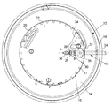
図1、2に示す修正装置10は、表示部材12による時間表示を修正する。この時間表示は、例えば日にち、月、曜日である。表示部材12は、従来と同様リング14を有する。このリング14上に時間表示マークが刻まれる。このリング14は、ピッチpの内歯16を具備する。この内歯16は、幅sの歯17から形成される。その結果、幅Sのスペースは、S=p−sである。表示部材12は、プレート18上に回転するようガイドされ、ジャンパー・スプリング20により角度的に(ある一定角度位置を占有するよう)配置される。内歯16を一部カバーしプレート18に固定されるホールディング・プレート22が、表示部材12を軸方向に沿って配置する。表示部材12の駆動機構は、図示されていない。駆動機構は、例えば日付表示の場合は、1日にワンステップだけ表示部材12を駆動する日付駆動車を有する。この日付駆動車は、中間時間車により駆動される。この機構は従来公知であり説明は割愛する。
The
修正装置10は、従来と同様に、プレート18を回転駆動するよう搭載される巻き上げステム24を有する。巻き上げステム24の外側端に巻き上げ竜頭(図示せず)を具備する。巻き上げステム24は、中立位置(巻き上げステム24が最も遠くに押し込まれた位置)と2つの駆動位置(巻き上げステム24が引き出される第1と第2の引出位置)とを占有する。スライド・ピニオン26は、巻き上げステム24に回転可能に取付けられる。巻き上げステム24は、スライド・ピニオン26が占有する部分に四角の断面を有する。言い換えると、スライド・ピニオン26は、巻き上げステム24の四角の断面のサイズと形状に合うような穴を有する。巻き上げステム24は、その第1端に第1直線状丸穴歯車28を、第2端にピッチpの第2丸穴歯車30を有する。この第2丸穴歯車30も直線状であるが、歯の形状は以下に述べるものでもよい。
The
スライド・ピニオン26は、引出ピース32とレバー34により構成される機構により従来と同様駆動される。引出ピース32とレバー34は、互いに共働して、ピニオンを、中立位置(巻き上げステム24が中立位置を占有する時)から、時間表示修正位置A(巻き上げステム24が第1引出位置を占有する時)に、その後、時間設定位置B(巻き上げステム24が第2引出位置を占有する時)に移動させる。スライド・ピニオン26を駆動するこの機構は、当業者に公知であり詳細な説明は割愛する。
The slide and
時間設定位置Bにおいては、スライド・ピニオン26は、第1丸穴歯車28を介して、中間歯車36と噛み合う。中間歯車36は、キャノン・ピニオン(図示せず)と機構的に連結されている。時間は、巻き上げステム24をいずれかの方向に動かすことにより設定できる。
At the time setting position B, the
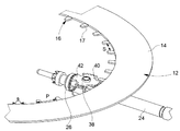
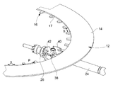
時間表示修正位置Aにおいては、スライド・ピニオン26は、第2丸穴歯車30を介して修正歯車38と噛み合う。修正歯車38は、ホールディング・プレート22に自由に回転するよう搭載される。修正歯車38は表示部材12の内歯16と噛み合う。巻き上げステム24とスライド・ピニオン26と修正歯車38と表示部材12から構成される組立体を図3に時間表示修正位置Aで示す。修正歯車38の特徴を図4に詳細に示す。
At the time display correction position A, the
修正歯車38は、ピッチpで頭部直径(最大外径)Dと脚部直径(凹み部直径)d1の大きな第1歯40を有する。この第1歯40は表示部材12の内歯16と噛み合う。第1歯40は内歯16と完全に相補的である(第1歯40は内歯16間に嵌り込む)。第1歯40は、(図4では4枚の)歯42から構成される。この歯42の幅Sは、2枚の隣り合う歯17の間のスペースに等しい。この幅Sは、s=P−Sである。sは歯17の幅に等しい。
The
歯42は、2個の半径方向に伸びる側面と、一定の角度毎に伸びる先端44とを有する。先端44は、(図4では5個の)第2歯46を形成するよう切断されている。この第2歯46は、不連続に形成され、第1歯40と同一面かつ同心である。第2歯46のピッチpは、第1歯40のピッチPよりも小さく、頭部直径(最大外径)Dは、第1歯40の頭部直径(最大外径)Dと等しく、その脚部直径(凹み部直径)d2は、第1歯40の脚部直径d1よりも大きい。第2歯46は、スライド・ピニオン26の第2丸穴歯車30と噛み合う。
The
第2歯46は、大きく不連続である。その理由は、第2歯46は第1歯40の歯42の先端44にのみ存在するからである。しかし修正装置10が適切に動作するためには、第2歯46は、少なくとも1枚の歯を介して、スライド・ピニオン26の第2丸穴歯車30と噛み合わなければならない。それ故に、2つの隣り合う歯42を分けている幅のスペースsは可能な限り小さい。しかし表示部材12の内歯16を形成する歯17の幅sよりも小さくてはいけない。従って、表示部材12の歯17の幅sは、可能な限り小さくなければならない。
The
巻き上げステム24が駆動されて、スライド・ピニオン26がポジションAに入ると、スライド・ピニオン26は、修正歯車38を回転駆動し、この修正歯車38が表示部材12を一方向あるいは反対方向に駆動する。かくして時間表示が修正される。
When the hoisting
上記の実施例の場合、第2丸穴歯車30と第2歯46は、直線状であり、これにより両方向の回転結合が可能となる。図5に示す実施例においては、第2丸穴歯車30と第2歯46は、鋸状の歯の形状をしており、その結果2つの歯は、Breguet toothingsのように一方向にのみ共働(回転)する。スライド・ピニオン26と修正歯車38は、表示部材を一方向回転にのみ修正できる一方向性カップリングを構成する。この種の結合の動作モードの詳細は、特許文献3に開示されている。
In the case of the above-described embodiment, the second
上記の修正装置10は、極めて単純かつ小型である。かくして電子機械式の極薄いムーブメントに適する。
The
本発明の変形例として、1個の歯42のみを有する修正歯車38は、1個の先端44が角度的に伸び、第2歯46を形成するよう切り込まれ、第2歯46を第1歯と同一面かつ同心に配置することもできる。
As a modification of the present invention, the
以上の説明は、本発明の一実施例に関するもので、この技術分野の当業者であれば、本発明の種々の変形例を考え得るが、それらはいずれも本発明の技術的範囲に包含される。特許請求の範囲の構成要素の後に記載した括弧内の番号は、図面の部品番号に対応し、発明の容易なる理解の為に付したものであり、発明を限定的に解釈するために用いてはならない。また、同一番号でも明細書と特許請求の範囲の部品名は必ずしも同一ではない。これは上記した理由による。 The above description relates to one embodiment of the present invention, and those skilled in the art can consider various modifications of the present invention, all of which are included in the technical scope of the present invention. The The numbers in parentheses described after the constituent elements of the claims correspond to the part numbers in the drawings, are attached for easy understanding of the invention, and are used for limiting the invention. Must not. In addition, the part numbers in the description and the claims are not necessarily the same even with the same number. This is for the reason described above.
10 修正装置
12 表示部材
14 リング
16 内歯
17 歯
18 プレート
20 ジャンパー・スプリング
24 巻き上げステム
26 スライド・ピニオン
28 第1丸穴歯車
30 第2丸穴歯車
32 引出ピース
34 レバー
38 修正歯車
40 第1歯
42 歯
44 先端
46 第2歯
DESCRIPTION OF
Claims (10)
前記第1歯(40)は、ピッチP、頭部直径D、脚部直径d1であり、
前記歯(42)は、先端(44)を有し、
前記先端(44)の少なくとも一部は、所定角度毎に伸び、
前記先端(44)の一部は、第2歯(46)を形成し、
前記第2歯(46)は、前記第1歯(40)と同一面でかつ同心であり、
前記第2歯(46)のピッチpは、前記第1歯(40)のピッチPより小さく、
前記第2歯(46)の頭部直径Dは、前記第1歯(40)の頭部直径Dに等しく、
前記第2歯(46)の脚部直径d2は、前記第1歯(40)の脚部直径d1よりも大きい
ことを特徴とする時計歯車。 In a planar timepiece gear (38) having a first tooth (40) comprising a plurality of teeth (42),
The first teeth (40) have a pitch P, a head diameter D, and a leg diameter d1,
Said tooth (42) has a tip (44);
At least a part of the tip (44) extends at a predetermined angle,
A portion of the tip (44) forms a second tooth (46);
The second tooth (46) is flush with and concentric with the first tooth (40);
The pitch p of the second teeth (46) is smaller than the pitch P of the first teeth (40),
The head diameter D of the second tooth (46) is equal to the head diameter D of the first tooth (40),
A timepiece gear having a leg diameter d2 of the second teeth (46) larger than a leg diameter d1 of the first teeth (40).
前記歯(42)は、それぞれ所定角度毎に伸び、
前記先端(44)は、不連続な第2歯(46)を形成し、
前記第2歯(46)は、前記第1歯(40)と同一面でかつ同心であり、
前記第2歯(46)のピッチpは、前記第1歯(40)のピッチPより小さく、
前記第2歯(46)の頭部直径Dは、前記第1歯(40)の頭部直径Dに等しく、
前記第2歯(46)の脚部直径d2は、前記第1歯(40)の脚部直径d1よりも大きい
ことを特徴とする請求項1記載の時計歯車。 The first tooth (40) is formed from a tooth (42) having a tip (44);
The teeth (42) each extend at a predetermined angle,
The tip (44) forms discontinuous second teeth (46);
The second tooth (46) is flush with and concentric with the first tooth (40);
The pitch p of the second teeth (46) is smaller than the pitch P of the first teeth (40),
The head diameter D of the second tooth (46) is equal to the head diameter D of the first tooth (40),
The timepiece gear according to claim 1, wherein the leg diameter (d2) of the second tooth (46) is larger than the leg diameter (d1) of the first tooth (40).
ことを特徴とする請求項1記載の時計歯車。 The timepiece gear according to claim 1, wherein the pitch P is an integral multiple of the pitch p.
ことを特徴とする請求項1または2記載の時計歯車。 The timepiece gear according to claim 1 or 2, wherein the second teeth (46) are serrated teeth.
ことを特徴とする請求項1または2記載の時計歯車。 3. The timepiece gear according to claim 1, wherein the second teeth (46) are linear.
前記歯(42)は、幅sで分離され、
前記歯(42)の幅Sは、前記2枚の歯(42)を分離する幅sよりも大きい
ことを特徴とする請求項1−4のいずれかに記載の時計歯車。 Said teeth (42) have a width S;
The teeth (42) are separated by a width s;
5. The timepiece gear according to claim 1, wherein a width S of the teeth (42) is larger than a width s separating the two teeth (42).
前記修正装置(10)は、ピニオン(26)と修正歯車(38)とを有し、
前記ピニオン(26)は、ピッチpの歯(30)を具備し、巻き上げステム(24)に搭載され、少なくとも1つの表示修正位置Aを占有し、
前記修正歯車(38)は、前記ピニオン(26)と表示部材(12)との間に搭載され、
前記修正歯車(38)は、先端(44)を有する歯(42)から形成される第1歯(40)を有し、
前記第1歯(40)は、ピッチPと頭部直径Dと脚部直径d1を有し、
前記歯(42)は、所定角毎に伸び、
前記先端(44)は、第2歯(46)を形成し、
前記第2歯(46)は、第1歯(40)と同一面でかつ同心であり、
前記第2歯(46)のピッチpは、前記第1歯(40)のピッチPより小さく、
前記第2歯(46)の頭部直径Dは、前記第1歯(40)の頭部直径Dに等しく、
前記第2歯(46)の脚部直径d2は、前記第1歯(40)の脚部直径d1よりも大きい
ことを特徴とする修正装置。 In the correction device (10) of the time display mechanism of the timepiece having the display member (12) having the internal teeth (16) of the pitch P,
The correction device (10) has a pinion (26) and a correction gear (38),
The pinion (26) comprises teeth (30) with a pitch p, is mounted on a winding stem (24) and occupies at least one display correction position A;
The correction gear (38) is mounted between the pinion (26) and the display member (12),
The correction gear (38) has first teeth (40) formed from teeth (42) having tips (44);
The first teeth (40) have a pitch P, a head diameter D, and a leg diameter d1,
The teeth (42) extend every predetermined angle,
The tip (44) forms a second tooth (46);
The second tooth (46) is flush with and concentric with the first tooth (40);
The pitch p of the second teeth (46) is smaller than the pitch P of the first teeth (40),
The head diameter D of the second tooth (46) is equal to the head diameter D of the first tooth (40),
The correction device according to claim 1, wherein a leg diameter d2 of the second tooth (46) is larger than a leg diameter d1 of the first tooth (40).
ことを特徴とする請求項7記載の修正装置。 The correction device according to claim 7, wherein the pinion (26) is slidably mounted between a time setting position B and a time display correction position A.
ことを特徴とする請求項8記載の修正装置。 9. The correction device according to claim 8, further comprising means (32, 34) for moving the pinion (26) from the time setting position B to the time display correction position A and vice versa.
ことを特徴とする請求項7−8のいずれかに記載の修正装置。 The correction device according to any one of claims 7 to 8, wherein the teeth (30) of the pinion (26) and the second teeth (46) of the correction gear (38) have a sawtooth shape. .
Applications Claiming Priority (2)
| Application Number | Priority Date | Filing Date | Title |
|---|---|---|---|
| EP07105669A EP1978420B1 (en) | 2007-04-04 | 2007-04-04 | Gear wheel for a timepiece and device for correction of a display mechanism for a timepiece incorporating such a wheel |
| EP07105669.1 | 2007-04-04 |
Publications (2)
| Publication Number | Publication Date |
|---|---|
| JP2008256687A JP2008256687A (en) | 2008-10-23 |
| JP5203003B2 true JP5203003B2 (en) | 2013-06-05 |
Family
ID=38941633
Family Applications (1)
| Application Number | Title | Priority Date | Filing Date |
|---|---|---|---|
| JP2008079830A Active JP5203003B2 (en) | 2007-04-04 | 2008-03-26 | Device for correcting the display mechanism of a watch and gears suitable for the device |
Country Status (7)
| Country | Link |
|---|---|
| US (1) | US7957226B2 (en) |
| EP (1) | EP1978420B1 (en) |
| JP (1) | JP5203003B2 (en) |
| CN (1) | CN101286038B (en) |
| AT (1) | ATE487962T1 (en) |
| DE (1) | DE602007010423D1 (en) |
| SG (1) | SG146583A1 (en) |
Families Citing this family (9)
| Publication number | Priority date | Publication date | Assignee | Title |
|---|---|---|---|---|
| EP2124112A1 (en) * | 2008-05-22 | 2009-11-25 | CT Time S.A. | Timepiece mechanism and module comprising such a mechanism |
| EP2428855B1 (en) * | 2010-09-08 | 2019-07-03 | Rolex S.A. | Clock piece fitted with a device for displaying predetermined time periods |
| CN103425038B (en) * | 2013-08-17 | 2015-11-04 | 吴中一 | Watch movement intermediate date wheel structure |
| JP6510781B2 (en) * | 2014-09-12 | 2019-05-08 | セイコーインスツル株式会社 | Gear body, time difference correction mechanism, movement for watch and watch |
| EP3144743B1 (en) * | 2015-09-15 | 2018-03-14 | ETA SA Manufacture Horlogère Suisse | Clock movement comprising a mechanism for correcting the date |
| EP3460586B1 (en) * | 2017-09-22 | 2022-04-06 | Montres Breguet S.A. | Device for winding and/or immobilising a marine chronometer |
| CN113485083B (en) * | 2020-12-04 | 2022-07-26 | 深圳穿金戴银科技股份有限公司 | Watchcase, watch timing structure and timing watch |
| EP4375763B1 (en) * | 2022-11-24 | 2025-09-10 | ETA SA Manufacture Horlogère Suisse | Clock movement comprising a mechanism for correcting a display |
| CN119247722B (en) * | 2024-11-15 | 2025-05-09 | 深圳市贝伦斯智能穿戴科技有限公司 | Calendar quick-pulling mechanism and reed mechanism based on face gear transmission |
Family Cites Families (29)
| Publication number | Priority date | Publication date | Assignee | Title |
|---|---|---|---|---|
| US161262A (en) | 1875-03-23 | Improvement in stem-winding watches | ||
| US951197A (en) | 1907-03-18 | 1910-03-08 | Martin A O'connor | Blower. |
| US1036954A (en) | 1909-08-26 | 1912-08-27 | Seth Thomas Clock Company | Stem winding and setting mechanism for clocks. |
| US1142051A (en) * | 1910-06-20 | 1915-06-08 | Providence Blower Company | Variable-speed gear. |
| US1538494A (en) * | 1923-02-06 | 1925-05-19 | Jesse D Tucker | Spring axle |
| CH347139A (en) | 1959-06-05 | 1960-06-15 | Marc Favre & Co S A | One-way coupling, in particular for automatic winding of timepieces |
| US3104517A (en) | 1962-01-29 | 1963-09-24 | United States Time Corp | Planetary gear winding mechanism |
| US3360922A (en) | 1966-03-11 | 1968-01-02 | Hamilton Watch Co | Electric watch calendar setting and detenting mechanism |
| FR1491183A (en) | 1966-09-05 | 1967-08-04 | Omega Brandt & Freres Sa Louis | One way coupling device |
| CH44067A4 (en) | 1967-01-12 | 1970-03-31 | ||
| GB1168745A (en) * | 1967-08-14 | 1969-10-29 | Seiko Instr & Electronics | Calendar Timepiece. |
| CH541828A (en) | 1970-09-25 | 1973-05-30 | Ebauches Bettlach Sa | Pull-out time-setting and winding mechanism for watch movement |
| AT319853B (en) * | 1971-07-27 | 1975-01-10 | Allemann Praez Smaschb Ets | Quick correction device for watches |
| JPS4933865U (en) | 1972-06-24 | 1974-03-25 | ||
| JPS56752B2 (en) | 1972-12-27 | 1981-01-09 | ||
| JPS58128556A (en) | 1982-01-25 | 1983-08-01 | Matsushita Electric Ind Co Ltd | Drive force transmission device |
| JPS59160791A (en) * | 1983-03-04 | 1984-09-11 | Citizen Watch Co Ltd | Gear train structure of electronic watch |
| DE3505733C1 (en) * | 1985-02-20 | 1986-10-23 | IWC International Watch Co AG, Schaffhausen | Clock |
| US5083300A (en) | 1991-07-10 | 1992-01-21 | Timex Corporation | Setting mechanism for a timepiece |
| CH681191B5 (en) | 1991-09-11 | 1993-08-13 | Ebauchesfabrik Eta Ag | |
| DE4316233A1 (en) * | 1993-05-14 | 1994-11-17 | Zahnradfabrik Friedrichshafen | Holder for a gear |
| JPH11183649A (en) | 1997-12-25 | 1999-07-09 | Seiko Instruments Inc | Clock with display correcting device |
| DE60233783D1 (en) * | 2002-05-28 | 2009-11-05 | Manuf Et Fabrique De Montres E | Inhibition for watches |
| EP1498788A1 (en) | 2003-07-14 | 2005-01-19 | Eterna SA | Display device for timepiece |
| EP1538494A1 (en) * | 2003-12-01 | 2005-06-08 | Watch-U-License AG | Antriebsvorrichtung für eine mechanische Uhr |
| DE602005014468D1 (en) | 2005-07-26 | 2009-06-25 | Montres Breguet Sa | Device with spindle for mounting and timing of watches |
| CN2852208Y (en) * | 2005-12-22 | 2006-12-27 | 东莞新精电子有限公司 | A New Watch Movement with Elastic Lever Mechanism and Friction Drive Timing Device |
| DE602005022742D1 (en) * | 2005-12-23 | 2010-09-16 | Swatch Group Res & Dev Ltd | Mechanism for displaying values in variable cycles, especially in a lunar and solar calendar |
| DE602007007888D1 (en) | 2007-04-04 | 2010-09-02 | Eta Sa Mft Horlogere Suisse | Elevator device with unidirectional coupling |
-
2007
- 2007-04-04 DE DE602007010423T patent/DE602007010423D1/en active Active
- 2007-04-04 AT AT07105669T patent/ATE487962T1/en not_active IP Right Cessation
- 2007-04-04 EP EP07105669A patent/EP1978420B1/en active Active
-
2008
- 2008-03-26 JP JP2008079830A patent/JP5203003B2/en active Active
- 2008-03-26 SG SG200802381-4A patent/SG146583A1/en unknown
- 2008-03-27 US US12/056,668 patent/US7957226B2/en not_active Expired - Fee Related
- 2008-04-03 CN CN2008100905906A patent/CN101286038B/en active Active
Also Published As
| Publication number | Publication date |
|---|---|
| JP2008256687A (en) | 2008-10-23 |
| DE602007010423D1 (en) | 2010-12-23 |
| US7957226B2 (en) | 2011-06-07 |
| EP1978420B1 (en) | 2010-11-10 |
| HK1125188A1 (en) | 2009-07-31 |
| SG146583A1 (en) | 2008-10-30 |
| CN101286038B (en) | 2012-02-01 |
| EP1978420A1 (en) | 2008-10-08 |
| US20080247277A1 (en) | 2008-10-09 |
| CN101286038A (en) | 2008-10-15 |
| ATE487962T1 (en) | 2010-11-15 |
Similar Documents
| Publication | Publication Date | Title |
|---|---|---|
| JP5203003B2 (en) | Device for correcting the display mechanism of a watch and gears suitable for the device | |
| JP5936844B2 (en) | Calendar display device and calendar watch | |
| CN102968042B (en) | Calendar mechanism | |
| CN107438797B (en) | Device for selecting a timepiece function | |
| JP6166724B2 (en) | Clock that can display two time zones | |
| JP5112841B2 (en) | Time setting member for time indicator | |
| JP5443857B2 (en) | Clock date mechanism | |
| JP5592415B2 (en) | Annual calendar device for watches | |
| JP6082077B2 (en) | Perpetual calendar with differential mechanism | |
| JP6069476B2 (en) | Timekeeping calendar mechanism | |
| JP4822561B2 (en) | Drive mechanism for date display on the clock calendar | |
| JP2018510348A5 (en) | ||
| JP6125686B2 (en) | Barrel with substantially constant torque characteristics | |
| JP5203004B2 (en) | Unidirectional coupling device and correction device having the same | |
| CN1735844A (en) | Calendar mechanism for displaying the date and day in one timepiece | |
| CN105683844A (en) | Calendar mechanism of clock movement | |
| US20130170325A1 (en) | Calendar mechanism and timepiece having the same | |
| JP5175816B2 (en) | Large date calendar date mechanism for watches | |
| US20180120770A1 (en) | Watch mechanism | |
| US8861313B2 (en) | Calendar mechanism and timepiece having the same | |
| GB2394568A (en) | Helical disc visual indicating device | |
| JP6180296B2 (en) | Pipe index wheel and time difference correction mechanism | |
| CN107045276B (en) | Calendar mechanism, movement, and timepiece | |
| US20120182839A1 (en) | Timepiece With Indication of the Time Zone Corresponding to a Chosen Time | |
| HK1125188B (en) | Correction device for timepiece display mechanism and wheel fitted thereto |
Legal Events
| Date | Code | Title | Description |
|---|---|---|---|
| A621 | Written request for application examination |
Free format text: JAPANESE INTERMEDIATE CODE: A621 Effective date: 20110215 |
|
| TRDD | Decision of grant or rejection written | ||
| A01 | Written decision to grant a patent or to grant a registration (utility model) |
Free format text: JAPANESE INTERMEDIATE CODE: A01 Effective date: 20130205 |
|
| A61 | First payment of annual fees (during grant procedure) |
Free format text: JAPANESE INTERMEDIATE CODE: A61 Effective date: 20130213 |
|
| R150 | Certificate of patent or registration of utility model |
Ref document number: 5203003 Country of ref document: JP Free format text: JAPANESE INTERMEDIATE CODE: R150 Free format text: JAPANESE INTERMEDIATE CODE: R150 |
|
| FPAY | Renewal fee payment (event date is renewal date of database) |
Free format text: PAYMENT UNTIL: 20160222 Year of fee payment: 3 |
|
| R250 | Receipt of annual fees |
Free format text: JAPANESE INTERMEDIATE CODE: R250 |
|
| R250 | Receipt of annual fees |
Free format text: JAPANESE INTERMEDIATE CODE: R250 |
|
| R250 | Receipt of annual fees |
Free format text: JAPANESE INTERMEDIATE CODE: R250 |
|
| R250 | Receipt of annual fees |
Free format text: JAPANESE INTERMEDIATE CODE: R250 |
|
| R250 | Receipt of annual fees |
Free format text: JAPANESE INTERMEDIATE CODE: R250 |
|
| R250 | Receipt of annual fees |
Free format text: JAPANESE INTERMEDIATE CODE: R250 |
|
| R250 | Receipt of annual fees |
Free format text: JAPANESE INTERMEDIATE CODE: R250 |
|
| R250 | Receipt of annual fees |
Free format text: JAPANESE INTERMEDIATE CODE: R250 |
|
| R250 | Receipt of annual fees |
Free format text: JAPANESE INTERMEDIATE CODE: R250 |
|
| R250 | Receipt of annual fees |
Free format text: JAPANESE INTERMEDIATE CODE: R250 |