JP5201963B2 - Confluence - Google Patents
Confluence Download PDFInfo
- Publication number
- JP5201963B2 JP5201963B2 JP2007310681A JP2007310681A JP5201963B2 JP 5201963 B2 JP5201963 B2 JP 5201963B2 JP 2007310681 A JP2007310681 A JP 2007310681A JP 2007310681 A JP2007310681 A JP 2007310681A JP 5201963 B2 JP5201963 B2 JP 5201963B2
- Authority
- JP
- Japan
- Prior art keywords
- drainage
- side wall
- pipe
- inflow
- opening edge
- Prior art date
- Legal status (The legal status is an assumption and is not a legal conclusion. Google has not performed a legal analysis and makes no representation as to the accuracy of the status listed.)
- Active
Links
Images


Landscapes
- Sink And Installation For Waste Water (AREA)
- Sewage (AREA)
Description
この発明は合流桝に関し、特にたとえば、複数の流入部を有する桝本体を備える、合流桝に関する。 The present invention relates to a merging rod, and more particularly to a merging rod including a ridge body having a plurality of inflow portions.
従来、合流桝は、充分に減速した排水が流入する屋外での使用を想定しているため、対面の流入部への越流を考慮した形状となっていない。しかし、たとえば屋内の床下に合流桝を設置した場合には、勢いのある排水が合流桝内に流入する可能性があり、その排水が対面の流入部へ越流してしまう恐れがある。 Conventionally, the confluence is assumed to be used outdoors where drained water that has been sufficiently slowed down, so it does not have a shape that takes into account the overflow to the inflow portion of the meeting. However, for example, when a confluence is installed under the floor of an indoor space, there is a possibility that vigorous wastewater flows into the confluence, and the wastewater may overflow to the inflow portion facing to the surface.
このような排水の越流を防止するために、たとえば特許文献1の技術では、桝本体内に仕切体を設けている。この仕切体は、上下方向の放射状仕切板と、隣同士の仕切板に亘る逆L字状天板とを含み、複数の流入口の桝本体内の開口側を区画して、排水をガイドしている。
桝本体内に流入する排水は、桝本体側壁の開口縁から中心方向に向かって略水平方向に飛び出し、重力の影響を受けて、次第にその流れ方向を鉛直下向きへと変えていく。しかし、特許文献1の技術では、桝本体内に仕切体を設けるので、桝本体側壁の開口縁と仕切体との距離が短くなっており、勢いのある排水が桝本体内に流入した場合には、排水は、その流れ方向が水平方向に近いまま仕切体に衝突することになる。流れ方向が水平方向に近い状態で仕切体に衝突した排水は、跳ね返って桝本体内から円滑に排出されなくなり、桝本体内を閉塞してしまう恐れがある。桝本体内が満水状態になると、桝本体内に負圧が発生し、合流桝の上流側に設けられる排水トラップを破封してしまう。 The waste water flowing into the cocoon body jumps out in the substantially horizontal direction from the opening edge of the cocoon body side wall toward the center, and gradually changes its flow direction vertically downward under the influence of gravity. However, in the technique of Patent Document 1, since the partition body is provided in the cocoon body, the distance between the opening edge of the heel body side wall and the partition body is shortened, and when vigorous drainage flows into the cocoon body, The drainage will collide with the partition while its flow direction is close to the horizontal direction. Drainage that collides with the partition in a state where the flow direction is close to the horizontal direction will bounce off and will not be smoothly discharged from the inside of the cocoon body, which may block the inside of the cocoon body. When the inside of the cocoon body is full of water, negative pressure is generated in the cocoon body, and the drain trap provided on the upstream side of the joining basin is broken.
それゆえに、この発明の主たる目的は、新規な、合流桝を提供することである。 Therefore, the main object of the present invention is to provide a novel confluence.
この発明の他の目的は、桝本体内に流入した排水を円滑に排出できる、合流桝を提供することである。 Another object of the present invention is to provide a merging soot that can smoothly drain the waste water that has flowed into the soot body.
この発明は、上記の課題を解決するために、以下の構成を採用した。なお、括弧内の参照符号および補足説明などは、本発明の理解を助けるために後述する実施の形態との対応関係を示したものであって、この発明を何ら限定するものではない。 The present invention employs the following configuration in order to solve the above problems. Note that reference numerals in parentheses and supplementary explanations indicate correspondence with embodiments described later in order to help understanding of the present invention, and do not limit the present invention.
第1の発明は、排水枝管から排水が流入する複数の流入部と、排水主管へ排水を流出する流出部とを有する桝本体を備える合流桝であって、流入部は、桝本体の側壁部から外方に向かって突出するように形成される短筒部、および短筒部の先端に形成され、排水枝管が接続される管接続部を含み、短筒部の管接続部側の開口縁の径を、排水枝管の内径と同じまたはほぼ同じ大きさにして、管接続部に接続した排水枝管の内面と短筒部の内面とが段差なく接続されるようにするとともに、短筒部の側壁部側の開口縁最下部が管接続部側の開口縁最下部より低い位置になるように高低差をつけた、合流桝である。 The first invention includes a plurality of inlet for wastewater flows from the drain branch pipe, met confluence basins comprise Masumoto body having an outlet portion for discharging the waste water into the drainage main pipe, the inlet section, the side wall of Masumoto body A short cylindrical portion formed so as to protrude outward from the portion , and a pipe connecting portion formed at the tip of the short cylindrical portion , to which a drainage branch pipe is connected, on the pipe connecting portion side of the short cylindrical portion The diameter of the opening edge is the same as or substantially the same as the inner diameter of the drainage branch pipe so that the inner surface of the drainage branch pipe connected to the pipe connection portion and the inner surface of the short cylinder portion are connected without any step, This is a merging rod with a difference in height so that the lowermost portion of the opening edge on the side wall portion side of the short cylindrical portion is positioned lower than the lowermost portion of the opening edge on the tube connection portion side.
第1の発明では、合流桝(10)は、複数の流入部(12)を有する桝本体(14)を含み、たとえば、戸建住宅の床(100)下に配置されて、住設機器から排出された排水を流す複数の排水枝管(102)と、排水を外部に排出する排水主管(106)とを繋ぐ。流入部は、桝本体の側壁部(22)から外方に向かって突出する短筒部(38)と、短筒部の一端に形成されて、排水枝管が接続される管接続部(40)とを含む。短筒部には、その側壁部側の開口縁(44)最下部が管接続部側の開口縁(46)最下部よりも低い位置になるように、高低差がつけられている。これにより、排水枝管から桝本体内に流入する排水は、側壁部側の開口縁よりも外側で落下し始める。したがって、勢いのある排水が流入しても、排水は、その流れ方向を適切に下向きに変え、他の流入部に越流することなど無く、流出部(30)から円滑に排出される。 In the first invention, the merging gutter (10) includes a gutter body (14) having a plurality of inflow portions (12), and is arranged, for example, under a floor (100) of a detached house, A plurality of drainage branch pipes (102) through which the discharged wastewater flows are connected to a drainage main pipe (106) through which the wastewater is discharged to the outside. An inflow part is formed in the short cylinder part (38) which protrudes outward from the side wall part (22) of a dredger main body, and the pipe connection part (40) which is formed in the end of a short cylinder part, and a drainage branch pipe is connected. ). The short cylinder portion is provided with a height difference so that the lowermost portion of the opening edge (44) on the side wall portion side is lower than the lowermost portion of the opening edge (46) on the tube connection portion side. As a result, the drainage flowing from the drainage branch pipe into the main body starts to fall outside the opening edge on the side wall portion side. Accordingly, even if vigorous wastewater flows in, the wastewater is smoothly discharged from the outflow portion (30) without changing the flow direction downward and overflowing to other inflow portions.
第1の発明によれば、排水の落下開始点を側壁部側の開口縁よりも外側にすることができるので、桝本体内に流入する排水を円滑に排出できる。 According to the first aspect of the invention, since the drain start point of the waste water can be outside the opening edge on the side wall portion side, the waste water flowing into the bag main body can be smoothly discharged.
第2の発明は、第1の発明に従属し、短筒部の管底は、管接続部側から側壁部側に向かって下り勾配となり、側壁部の下部には、中心方向に向かって下り勾配となる底壁部が形成され、この底壁部の中心部に、流出部が形成される。 A second invention is according to the first invention, the tube bottom of the short tube portion is Ri Do a downward slope toward the side wall portion side from the tube connection side, to the lower portion of the side wall portion, toward the center Te bottom wall portion serving as a downward slope is formed in the center of the bottom wall, the outflow portion Ru is formed.
第2の発明では、短筒部(38)の管底(42)に形成される下り勾配、つまり傾斜によって、側壁部側の開口縁(44)最下部と管接続部側の開口縁(46)最下部とに高低差がつけられる。これにより、勢いの無い排水が排水枝管から流入した場合には、排水は短筒部の管底に沿って流れ、管底の下り勾配によって若干加速されて、流出部(30)から速やかに排出される。もちろん、第1の発明と同様に、排水の落下開始点を側壁部側の開口縁よりも外側にすることができるので、勢いのある排水が排水枝管から流入した場合にも、排水を円滑に排出できる。 In the second aspect of the invention, the bottom edge (44) at the side of the side wall and the opening edge (46 at the side of the pipe connecting part) are formed by the downward slope, that is, the inclination formed at the pipe bottom (42) of the short cylinder part (38). ) A difference in height is given to the bottom. As a result, when drainage with no momentum flows in from the drainage branch pipe, the drainage flows along the bottom of the short cylinder part, is slightly accelerated by the downward slope of the bottom of the pipe, and promptly from the outflow part (30). Discharged. Of course, as in the first aspect of the invention, the drainage start point of the drainage can be outside the opening edge on the side wall portion side, so even when vigorous drainage flows from the drainage branch pipe, Can be discharged.
第3の発明は、複数の流入部を有する桝本体を備える合流桝であって、流入部は、桝本体の側壁部から外方に向かって突出するように形成される短筒部、短筒部の管底の両側に形成される縦壁、および短筒部に形成される管接続部を含み、短筒部の側壁部側の開口縁最下部が管接続部側の開口縁最下部より低い位置にある、合流桝である。 A third aspect of the invention is a merging gutter having a gutter main body having a plurality of inflow portions, wherein the inflow portion is formed so as to protrude outward from the side wall portion of the gutter main body. Including a vertical wall formed on both sides of the tube bottom of the tube portion and a tube connection portion formed on the short tube portion, the lowermost opening edge on the side wall portion side of the short tube portion being lower than the lowermost opening edge on the tube connection portion side It is a confluence at a low position .
第3の発明では、短筒部(38)の管底(42)の両側から垂直方向に立ち上がるように縦壁(48)が形成される。この縦壁によって排水の幅が規制され、排水幅の横方向への拡大を抑制できる。したがって、桝本体(14)内に流入する排水をより適切に排出できる。 In the third aspect of the invention, the vertical wall (48) is formed so as to rise vertically from both sides of the tube bottom (42) of the short cylindrical portion (38). The width of the drainage is regulated by the vertical wall, and the lateral expansion of the drainage width can be suppressed. Therefore, the waste water flowing into the bag main body (14) can be discharged more appropriately.
第4の発明は、第1ないし第3のいずれかの発明に従属し、桝本体内に設けられ、各流入部の間を区画する仕切体をさらに備える。 A fourth invention is dependent on any one of the first to third inventions, and further includes a partition provided in the bag main body and partitioning the inflow portions.
第4の発明では、桝本体(14)内に仕切体(52)が設けられる。仕切体は、仕切板(56)によって各流入部(12)の間を区画し、流入部から流入する排水の流れ方向を流出部(30)の方向にスムーズに変化させる案内機能によって、他の流入部への排水の越流を防止する。この場合、仕切体と側壁部(22)側の開口縁(44)との間の距離は短くなるが、流入部に短筒部(38)を形成し、排水の落下開始点を側壁部(22)側の開口縁(44)よりも外側にしているので、仕切体と排水の落下開始点との間の距離は長くなる。したがって、排水は、その流れ方向が下向きに近い状態で仕切体と衝突することになるので、跳ね返ることなど無く、円滑に流出部から排出される。 In the fourth invention, the partition body (52) is provided in the bag main body (14). The partition body separates between the inflow portions (12) by the partition plate (56), and other functions are provided by a guide function for smoothly changing the flow direction of the wastewater flowing in from the inflow portion toward the outflow portion (30). Prevent overflow of drainage into the inflow. In this case, the distance between the partition and the opening edge (44) on the side wall portion (22) side is shortened, but a short cylinder portion (38) is formed at the inflow portion, and the falling start point of the drainage is defined as the side wall portion ( 22) Since it is outside the opening edge (44) on the side, the distance between the partition and the falling start point of the drainage becomes longer. Therefore, since the wastewater collides with the partition body in a state where the flow direction is close to the downward direction, the wastewater is smoothly discharged from the outflow portion without rebounding.
この発明によれば、排水の落下開始点を側壁部側の開口縁よりも外側にすることができるので、桝本体内に流入した排水を円滑に排出できる。 According to this invention, since the falling start point of the waste water can be outside the opening edge on the side wall portion side, the waste water that has flowed into the main body can be discharged smoothly.
この発明の上述の目的,その他の目的,特徴および利点は、図面を参照して行う以下の実施例の詳細な説明から一層明らかとなろう。 The above object, other objects, features and advantages of the present invention will become more apparent from the following detailed description of embodiments with reference to the drawings.
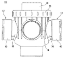
図1を参照して、この発明の一実施例である合流桝10は、戸建住宅などの床100下に配置されて、トイレや風呂などの住設機器から排出された生活排水を流す複数の排水枝管102と、基礎104を貫通して生活排水を外部に排出する排水主管106とを繋ぐ。図2および図3に示すように、合流桝10は、複数の流入部12を有する桝本体14、桝本体14の点検口16に装着される蓋18、および蓋18の抜け出しを防止するための押え部材20を含み、塩化ビニル等の合成樹脂によって形成される。
Referring to FIG. 1, a
図4に示すように、桝本体14は、射出成形などによって形成され、略円筒形状の側壁部22を含む。側壁部22の内径は、たとえば155mmである。側壁部22の上端24は開口しており、その上端開口が点検口16として利用される。この点検口16には、詳細は後述する蓋18が着脱自在に装着される。また、側壁部22の上端24には、外側に向かって突出する4つの第1爪部26が形成される。
As shown in FIG. 4, the bag
側壁部22の下部には、テーパ状の底壁部28が形成され、底壁部28の上面、すなわち桝本体14の底面は中心方向に向かって下り勾配となる。この底壁部28の中心部に、円筒形状の流出部30が下方に延びるように形成される。流出部30は、排水主管106へと排水を流出する流出口であると共に、排水主管106と接着接合などによって接続される接続部でもある。流出部30の外径は、たとえば106mmであり、その高さは、たとえば40mmである。
A tapered
また、側壁部22は、一方が内側に向かって凹んでおり、そこに段差部32が形成される。段差部32の両側端上部のそれぞれは段差状になっており、そこに第1支持部34が形成され、その第1支持部34の水平面同士を結ぶように、円弧状に突出する第2支持部36が形成される。
Moreover, one side of the
側壁部22の段差部32側を除く3方側のそれぞれには、外方に向かって略水平方向に突出する流入部12が形成される。流入部12は、排水枝管102からの排水が流入する流入口であると共に、排水枝管102と接着接合などによって接続される接続部でもある。この実施例では、3つの流入部12が設けられ、3つの排水枝管102からの排水が流入(合流)可能となっている。
An
具体的には、図5を参照して、流入部12は、側壁部22から外方に向かって突出する略円筒状の短筒部38、および短筒部38の一端に形成される管接続部40を含む。短筒部38は、管接続部40から側壁部22に向かって下り勾配となる管底42を有し、短筒部38の側壁部22側の開口縁44最下部は、管接続部40側の開口縁46最下部より低い位置に位置する。また、短筒部38には、その管底42の両側から垂直方向に立ち上がる縦壁48が形成され、短筒部38の底部は、管底42と縦壁48とによって溝状になっている。短筒部38の管接続部40側の開口縁46の径は、排水枝管102の内径と同じ、或いはほぼ同じ大きさであり、排水枝管102の内面と短筒部38の内面とは滑らかに接続される。短筒部38の管底42の下り勾配は、たとえば、水平距離が10−50mmであるのに対して、高低差が2−20mmになるように形成される。
Specifically, referring to FIG. 5,
管接続部40は、排水枝管102の管端を受け入れる受口であって、略円筒状に形成される。管接続部40の外面端部には、係止溝50が形成される。流入部12に排水枝管102を接続しないときには、この係止溝50を利用してキャップが装着され、排水の漏れが防止される。管接続部40の内径は、排水枝管102の外径と同じ、或いはほぼ同じ大きさであり、たとえば90mmである。また、管接続部40の軸方向の長さは、たとえば40mmである。
The
また、桝本体14の内部には、各流入部12の間を区画する仕切体52が着脱自在に設けられる。具体的には、図6に示すように、仕切体52は、射出成形などによって形成され、当接板54および仕切板56を備える。
Moreover, the
当接板54は、桝本体14の段差部32と対向するように形成される板状体であって、その外面の両側部上部は、段差部32の両側端と沿う。また、当接板54の上端には、外側に向かって突出する第1当接部58が形成される。この第1当接部58は、段差部32の段差状の第1支持部34に沿う形状に形成され、桝本体14に仕切体52を取り付けたときには、第1当接部58と第1支持部34とが当接する(図2参照)。
The
仕切板56は、各流入部12の間を区画して、他の流入部12への排水の越流を防止するものであり、各流入部12に対向する位置のそれぞれに形成される。具体的には、仕切板56は、流入部12に対向する主面56aを有し、主面56aの下端中央から上方および両側方に向かうに伴い、流入部12に向かって湾曲する板状体に形成される。つまり、仕切板56は、流入部12の側壁部22側の開口縁44を庇状に覆い、仕切板56の側面上部56bは、開口縁44の上側半周に亘って、桝本体14の側壁部22の内面に沿う(図2参照)。また、仕切板56の側面下部56cは、下端に向かうに伴い内側に向かって放物線を描くように湾曲する。つまり、仕切板56の側面下部56cと桝本体14の側壁部22の内面とは離れており、その間には空間が形成される。この空間は、仕切板56によって区画される排水の通路同士を、桝本体14の周方向に連通する。
The
また、仕切体52は、その外面が仕切板56の側面上部56bと同一面となる壁部60を備える。この壁部60は、当接板54と一体となって略円筒形に形成され、壁部60の外面は側壁部22の内面に沿う。壁部60の上端には、その全周に亘って、第1当接部58と一体となって外方に向かって突出する第2当接部62が形成される。桝本体14に仕切体52を取り付けたときには、第2当接部62と第2支持部36とが当接し、第1当接部58および第2当接部62の上面は、段差部32の上面と同一面を形成する(図2参照)。
The
このような仕切体52は、流入部12から流入する排水を案内して、排水の流れ方向を流出部30の方向、すなわち下向きにスムーズに変化させる案内機能を有し、他の流入部12への排水の越流を防止する。また、一度に多量の排水が桝本体14内に流入した場合には、仕切板56の側面下部56cと側壁部22との間の空間を通して、排水を周方向(横方向)にも流し、桝本体14内での満水状態の発生を防止する。
Such a
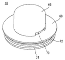
また、桝本体14の点検口16には、その内部に一方通気弁64を備える蓋18が着脱自在に装着される。図7に示すように、蓋18は、射出成形などによって形成され、有頂円筒状の内筒部66、および内筒部66の外面下部に形成される鍔部68を備える。内筒部66には、鍔部68の上面に沿うように、桝本体14内と外部とを連通するための通気孔70が形成される。また、鍔部68の下面には、円筒形状の嵌合部72が形成される。嵌合部72は、桝本体14の点検口16に嵌め込まれる部位であり、蓋18を桝本体14に取り付けたときには、嵌合部72の下端と、第1当接部58、第2当接部62および段差部32の上面とが当接する(図2参照)。したがって、上述の仕切体52は、桝本体14と蓋18とによって挟まれる状態になるので、蓋18が桝本体14にしっかりと固定されていれば、仕切体52もしっかりと固定される。また、嵌合部72の外面にはOリング等のシール部材74が装着され、桝本体14の側壁部22内面と嵌合部72外面との間の気密性および水密性が確保される。
Moreover, the lid | cover 18 which has the one
一方通気弁64は、蓋18とは別体として形成され、バヨネット結合またはネジ結合などを利用して、内筒部66の内部に取り付けられる(図2参照)。一方通気弁64は、通常時には、外部への排水および悪臭の漏れを確実に防止する。一方、桝本体14内で負圧が発生したときには、通気孔70と桝本体14内とを連通させて、外部の空気を桝本体14内に取り込み、桝本体14内を大気圧に保つ。
On the other hand, the
また、桝本体14には、蓋18の上から押え部材20が取り付けられる。押え部材20は、蓋18が桝本体14から不用意に外れることを防止すると共に、通気孔70に空気を導入するための空気通路を形成する。
A
具体的には、図8に示すように、押え部材20は、ドーナツ板状に形成される上壁部76を備える。上壁部76の中央に形成される円形の孔78の径は、蓋18の内筒部66の外径とほぼ同じ大きさに設定され、孔78の縁と内筒部66の外面とは当接する。また、上壁部76の下面周縁部には、下方向に延びる短円筒形状の側壁部80が形成される。この側壁部80の内面には、桝本体14の4つの第1爪部26と対応する位置に、内側に向かって突出する4つの第2爪部82が形成される。また、上壁部76の下面には、蓋18の通気孔70の高さに相当する高さを有する嵩上部84が形成される。
Specifically, as shown in FIG. 8, the pressing
桝本体14に押え部材20を取り付ける際には、先に桝本体14の点検口16に蓋18を装着しておき、その蓋18の上から押え部材20を取り付ける。具体的には、押え部材20の上壁部76の孔78に蓋18の内筒部66を挿通し、押え部材20の側壁部80内に、蓋18と桝本体14の側壁部22の上端部分とを差し込む。そして、押え部材20を周方向に回転させて、桝本体14の第1爪部26と押え部材20の第2爪部82とを勘合させることによって、桝本体14に押え部材20を固定する。つまり、押え部材20の取り付けには、差し込んで回転させることによって固定するバヨネット結合が利用される。
When attaching the
桝本体14に押え部材20を取り付けると、押え部材20の第2爪部82上面は、桝本体14の第1爪部26下面と当接し、蓋18の鍔部68上面は、押え部材20の嵩上部84の下端と当接する(図2参照)。押え部材20は、第1爪部26と第2爪部82との当接によって上方への動きが規制されるので、その押え部材20によって押えられる蓋18は、桝本体14にしっかりと固定される。このように蓋18と別体として形成した押え部材20を用いることで、蓋18の着脱性が向上する。
When the pressing
また、このとき、押え部材20の上壁部76下面と蓋18の鍔部68上面との間には、通気孔70に空気を導入するための空気通路86が形成され、押え部材20は、蓋18の鍔部68の上面上方を完全に覆う(図2参照)。これにより、蓋18の鍔部68上面に埃などが堆積し難くなるので、蓋18の通気孔70から桝本体14内に外気を取り込むときに、それと同時に埃などを吸引してしまうことが防止され、一方通気弁64の機能低下を防止できる。
At this time, an
このような合流桝10は、上述したように、戸建住宅の床100下などに設置されて、排水枝管102と排水主管106とを繋ぐ。このため、住設機器から排出された排水は、排水枝管102を流れて流入部12から桝本体14内に流入し、流出部30から排水主管106へと排出される。
As described above, the merging
ここで、排水枝管102から桝本体14内に流入する排水が充分に減速されている場合、つまり排水の勢いが無い場合には、排水は、流入部12の短筒部38の管底42に沿って流れ、管底42の下り勾配によって若干加速されて、自重によって速やかに流出部30から排出される。
Here, when the drainage flowing into the
また、排水の勢いが比較的弱い場合、排水は、流入部12の短筒部38の管底42に沿って流れ、側壁部22側の開口縁44から中心方向に向かって飛び出す。そして、自重によって、或いは仕切体52の案内機能によって、その流れ方向を鉛直下向きへと変え、流出部30から円滑に排出される。
When the momentum of the drainage is relatively weak, the drainage flows along the
さらに、排水の勢いが強い場合、排水は、流入部12の短筒部38の管底42の下り勾配が始まる地点から飛び出すと共に、その地点から自重によって落下し始める。そして、仕切体52の案内機能によって、その流れ方向を鉛直下向きへと変え、流出部30から排出される。このとき、排水が落下を開始する地点(落下開始点)と仕切体52(具体的には仕切板56の主面56a)との間の距離が短いと、排水は、その流れ方向が水平方向に近いまま仕切体52と衝突して跳ね返ってしまう。つまり、仕切体52の案内機能を超える勢いで排水が仕切体52と衝突して、排水は円滑に排出されなくなってしまう。しかし、この実施例のように、排水の落下開始点と仕切体52との距離が長いと、排水は、その流れ方向が下向きに近い状態になって仕切体52と衝突するので、仕切体52の案内機能が適切に発揮されて、排水は円滑に排出される。
Further, when the momentum of the drainage is strong, the drainage jumps out from the point where the descending slope of the
すなわち、特許文献1の技術のように、桝本体内の開口縁から排水の落下が始まるようにすると、落下開始点と仕切体との距離が近くなってしまい、勢いのあるまま排水が仕切体と衝突して跳ね返るので、排水を円滑に排出できない。 That is, if the drainage of the drainage starts from the opening edge in the main body as in the technique of Patent Document 1, the distance between the start point of the fall and the partition becomes close, and the drainage is separated from the partition with vigor. Since it collides and bounces, the drainage cannot be discharged smoothly.
これに対して、この実施例では、その管底42が下り勾配となる短筒部38を流入部12に形成したので、排水の落下開始点が仕切体52から離れた地点となる。これにより、排水が仕切体52と衝突するときには、排水の流れ方向が予め下向きに近い状態に変わり、排水の水平方向の勢いは弱められている。したがって、排水は、仕切体52と衝突しても水平方向に跳ね返ることは無く、仕切体52の仕切板56の主面56aを滑るようにして、円滑に流出部30から排出される。
On the other hand, in this embodiment, since the
また、短筒部38の管底42の両側から立ち上がる壁部48を形成したので、排水の幅を規制でき、排水幅の横方向への拡大を抑制できる。これにより、勢いのある排水が桝本体14内に流入しても、排水は仕切体52と確実に衝突して、仕切体52の案内機能によってその流れ方向を下向きに変える。したがって、仕切板56の側面下部56cと桝本体14の側壁部22との間の空間は、一度に多量の排水が桝本体14内に流入する非常時にのみ利用されることになり、この空間を通って他の流入部12に排水が越流することはない。
Moreover, since the
この実施例によれば、流入部12に、その管底42に下り勾配を有する短筒部38を形成したので、排水の落下開始点を側壁部22側の開口縁44よりも外側にすることができ、排水の落下開始点を仕切体52から離すことができる。これにより、桝本体14内に流入した排水の流れ方向を適切に下向きに変えることができ、排水を円滑に排出できる。したがって、桝本体14内が満水状態になることを防止でき、合流桝10の上流側に設けられる排水トラップの破封を防止できる。また、排水性能が向上するので、合流桝10を小型化できる。
According to this embodiment, since the short
なお、上述の実施例では、蓋18と仕切体52とを別体として成形したが、これに限定されず、蓋18と仕切体52とは一体に成形されていてもよい。また、桝本体14内に仕切体52を設けるようにしたが、仕切体52は必ずしも設ける必要はない。仕切体52を設けない場合でも、流入部12に、その管底42に下り勾配を有する短筒部38を形成することによって、他の流入部12から離れた位置で排水の落下を開始させることができるので、他の流入部12への越流を防止でき、排水を円滑に排出できる。
In the above-described embodiment, the
また、上述の実施例では、短筒部38の管底42の下り勾配によって、その側壁部22側の開口縁44最下部が管接続部40側の開口縁46最下部より低い位置になるように高低差を設けたが、これに限定されず、この高低差は、段差によって設けることもできる。ただし、段差によって高低差を設けると、排水枝管102から流入する排水の勢いが弱い場合には、その段差の位置で排水の流れが悪くなって、ゴミ等が堆積してしまう恐れがある。したがって、側壁部22側の開口縁44最下部と管接続部40側の開口縁46最下部との高低差は、図1に示す実施例のように、勾配つまり傾斜によって形成することが望ましい。
Further, in the above-described embodiment, the lowermost portion of the opening
また、短筒部38の管底42の下り勾配は、管底42の軸方向全長に亘って形成するようにしてもよいし、管底42の一部が下り勾配となるように形成してもよい。
In addition, the descending slope of the
また、管底42に下り勾配を有する短筒部38を全ての流入部12に形成する必要はない。たとえば、1つの流入部12のみに短筒部38を形成し、勢いのある排水が流れる排水枝管102をその流入部12に接続するようにするとよい。
Further, it is not necessary to form the short
さらに、上述の実施例では、流入部12の管接続部40を受口としたが、これに限定されず、管接続部40を差口としてもよい。また、管接続部40と排水枝管102との接合方法は、接着接合に限定されず、たとえば、これらをゴム輪接合することもできる。また、流入部12の短筒部38および管接続部40を略円筒状に形成したが、これに限定されず、楕円筒状や卵筒状などに形成してもかまわない。
Furthermore, in the above-described embodiment, the
また、上述の実施例では、3つの流入部12を設けたが、これに限定されず、2つの流入部12を設けることもできるし、4つ以上の流入部12を設けることもできる。
Moreover, in the above-mentioned Example, although the three
また、上述の実施例では、桝本体14に蓋18および押え部材20を取り付けるようにしたが、これらは必ずしも必要ではなく、蓋18および押え部材20を設けないこともあるし、蓋18および押え部材20を適宜な形状および構成に変更することもある。
In the above-described embodiment, the
また、上述の実施例では、一般住宅などの床100下に合流桝10を配管したが、これに限定されず、合流桝10は、屋外の排水管および下水管などに配管することもできる。また、合流桝10は、流出部30を桝本体14の底壁部28に形成して排水を下方に排出する、所謂ドロップ桝であることに限定されず、流出部30を桝本体14の側壁部22に形成して、側方から排水を流出する桝であってもよい。
Moreover, in the above-mentioned Example, although the confluence | merging
なお、上述した径や高さ等の具体的数値は、いずれも単なる一例であり、必要に応じて適宜変更可能である。 Note that the specific numerical values such as the diameter and height described above are merely examples, and can be appropriately changed as necessary.
10 …合流桝
12 …流入部
14 …桝本体
18 …蓋
20 …押え部材
30 …流出部
38 …短筒部
40 …管接続部
42 …短筒部の管底
44,46 …短筒部の開口縁
48 …短筒部の縦壁
52 …仕切体
DESCRIPTION OF
Claims (4)
前記流入部は、
前記桝本体の側壁部から外方に向かって突出するように形成される短筒部、および
前記短筒部の先端に形成され、前記排水枝管が接続される管接続部を含み、
前記短筒部の前記管接続部側の開口縁の径を、前記排水枝管の内径と同じまたはほぼ同じ大きさにして、前記管接続部に接続した前記排水枝管の内面と前記短筒部の内面とが段差なく接続されるようにするとともに、前記短筒部の前記側壁部側の開口縁最下部が前記管接続部側の開口縁最下部より低い位置になるように高低差をつけた、合流桝。 A plurality of inlet drainage from the drain branch pipe flows, meet confluence basins comprise Masumoto body having an outlet portion for discharging the waste water into the waste water main pipe,
The inflow part is
A short cylinder part formed so as to protrude outward from the side wall part of the jar body , and a pipe connection part formed at the tip of the short cylinder part to which the drainage branch pipe is connected ,
The inner diameter of the drainage branch pipe connected to the pipe connection part and the short cylinder, with the diameter of the opening edge of the short cylinder part on the pipe connection part side being the same as or substantially the same as the inner diameter of the drainage branch pipe The inner surface of the tube portion is connected without a step, and the height difference is set so that the lowermost portion of the opening edge on the side wall portion side of the short tube portion is lower than the lowermost portion of the opening edge on the tube connection portion side. The confluence that I put on .
前記流入部は、
前記桝本体の側壁部から外方に向かって突出するように形成される短筒部、
前記短筒部の管底の両側に形成される縦壁、および
前記短筒部に形成される管接続部を含み、
前記短筒部の前記側壁部側の開口縁最下部が前記管接続部側の開口縁最下部より低い位置にある、合流桝。 A merging gutter comprising a gutter body having a plurality of inflow portions,
The inflow part is
A short tube portion formed so as to protrude outward from the side wall portion of the heel body,
A vertical wall formed on both sides of the tube bottom of the short cylinder part , and
Including a pipe connecting part formed in the short cylinder part,
A junction rod in which the lowermost opening edge on the side wall portion side of the short cylindrical portion is located at a position lower than the lowermost opening edge on the pipe connecting portion side .
Priority Applications (1)
| Application Number | Priority Date | Filing Date | Title |
|---|---|---|---|
| JP2007310681A JP5201963B2 (en) | 2007-11-30 | 2007-11-30 | Confluence |
Applications Claiming Priority (1)
| Application Number | Priority Date | Filing Date | Title |
|---|---|---|---|
| JP2007310681A JP5201963B2 (en) | 2007-11-30 | 2007-11-30 | Confluence |
Publications (2)
| Publication Number | Publication Date |
|---|---|
| JP2009133131A JP2009133131A (en) | 2009-06-18 |
| JP5201963B2 true JP5201963B2 (en) | 2013-06-05 |
Family
ID=40865258
Family Applications (1)
| Application Number | Title | Priority Date | Filing Date |
|---|---|---|---|
| JP2007310681A Active JP5201963B2 (en) | 2007-11-30 | 2007-11-30 | Confluence |
Country Status (1)
| Country | Link |
|---|---|
| JP (1) | JP5201963B2 (en) |
Families Citing this family (3)
| Publication number | Priority date | Publication date | Assignee | Title |
|---|---|---|---|---|
| JP2020066894A (en) * | 2018-10-23 | 2020-04-30 | Toto株式会社 | Joint and system for combined urinals |
| JP6820906B2 (en) * | 2018-12-28 | 2021-01-27 | 積水化学工業株式会社 | Drainage piping structure |
| JP6799194B2 (en) * | 2020-09-10 | 2020-12-09 | 積水化学工業株式会社 | Drainage piping structure |
Family Cites Families (4)
| Publication number | Priority date | Publication date | Assignee | Title |
|---|---|---|---|---|
| JPH09189042A (en) * | 1996-01-10 | 1997-07-22 | Sekisui Chem Co Ltd | Synthetic resin manhole |
| JP3791770B2 (en) * | 2001-10-09 | 2006-06-28 | アロン化成株式会社 | Synthetic resin assembly |
| JP4537965B2 (en) * | 2006-02-08 | 2010-09-08 | アロン化成株式会社 | Multiple inflow drainage |
| JP2007308962A (en) * | 2006-05-18 | 2007-11-29 | Kubota Ci Kk | Catch basin |
-
2007
- 2007-11-30 JP JP2007310681A patent/JP5201963B2/en active Active
Also Published As
| Publication number | Publication date |
|---|---|
| JP2009133131A (en) | 2009-06-18 |
Similar Documents
| Publication | Publication Date | Title |
|---|---|---|
| US8677519B2 (en) | Drainage connector | |
| US8590068B2 (en) | Anti-overflow toilet and method | |
| US20130000035A1 (en) | Wastewater Drain With Odor Trap | |
| KR101009474B1 (en) | Wrong drainage vent | |
| US9732506B2 (en) | Anti-overflow toilet with detachable primary and secondary drain tubes | |
| JP5201963B2 (en) | Confluence | |
| JP4895892B2 (en) | Join | |
| JP2008150785A (en) | Rainwater flow-down promoting device in downpipe | |
| JP5530420B2 (en) | Join | |
| JP5269401B2 (en) | 桝 | |
| JP5576027B2 (en) | Ventilation integrated fitting | |
| JP5469807B2 (en) | 接合 Joining structure and installation method | |
| JP5601451B2 (en) | Drain socket, flush toilet equipped with the same, and drain pipe member | |
| JP7429634B2 (en) | siphon drainage system | |
| KR101070808B1 (en) | Wrong drainage vent | |
| JP5894229B2 (en) | Drainage fitting structure and adjustment ring | |
| JP2003206560A (en) | Drain trap with suction valve | |
| JP4454412B2 (en) | Underfloor piping ventilation structure | |
| JP5369397B2 (en) | Drain socket | |
| JP5201970B2 (en) | 桝 | |
| JP4341070B2 (en) | Drainage socket for flush toilet | |
| JP6335953B2 (en) | Drainage joint and drainage system using the same | |
| JP7393320B2 (en) | siphon drainage system | |
| KR102749076B1 (en) | Drainage trap for plumbing on slab | |
| JP4114204B2 (en) | Drain socket |
Legal Events
| Date | Code | Title | Description |
|---|---|---|---|
| A625 | Written request for application examination (by other person) |
Free format text: JAPANESE INTERMEDIATE CODE: A625 Effective date: 20100917 |
|
| A977 | Report on retrieval |
Free format text: JAPANESE INTERMEDIATE CODE: A971007 Effective date: 20120307 |
|
| A131 | Notification of reasons for refusal |
Free format text: JAPANESE INTERMEDIATE CODE: A131 Effective date: 20120313 |
|
| A521 | Written amendment |
Free format text: JAPANESE INTERMEDIATE CODE: A523 Effective date: 20120510 |
|
| TRDD | Decision of grant or rejection written | ||
| A01 | Written decision to grant a patent or to grant a registration (utility model) |
Free format text: JAPANESE INTERMEDIATE CODE: A01 Effective date: 20130212 |
|
| A61 | First payment of annual fees (during grant procedure) |
Free format text: JAPANESE INTERMEDIATE CODE: A61 Effective date: 20130212 |
|
| R150 | Certificate of patent or registration of utility model |
Ref document number: 5201963 Country of ref document: JP Free format text: JAPANESE INTERMEDIATE CODE: R150 Free format text: JAPANESE INTERMEDIATE CODE: R150 |
|
| FPAY | Renewal fee payment (event date is renewal date of database) |
Free format text: PAYMENT UNTIL: 20160222 Year of fee payment: 3 |
|
| S533 | Written request for registration of change of name |
Free format text: JAPANESE INTERMEDIATE CODE: R313533 |
|
| R350 | Written notification of registration of transfer |
Free format text: JAPANESE INTERMEDIATE CODE: R350 |