JP5200247B2 - Ignition electrode - Google Patents
Ignition electrode Download PDFInfo
- Publication number
- JP5200247B2 JP5200247B2 JP2009516665A JP2009516665A JP5200247B2 JP 5200247 B2 JP5200247 B2 JP 5200247B2 JP 2009516665 A JP2009516665 A JP 2009516665A JP 2009516665 A JP2009516665 A JP 2009516665A JP 5200247 B2 JP5200247 B2 JP 5200247B2
- Authority
- JP
- Japan
- Prior art keywords
- electrode
- alloy
- spark
- center electrode
- sparking
- Prior art date
- Legal status (The legal status is an assumption and is not a legal conclusion. Google has not performed a legal analysis and makes no representation as to the accuracy of the status listed.)
- Expired - Fee Related
Links
Images


Classifications
-
- H—ELECTRICITY
- H01—ELECTRIC ELEMENTS
- H01T—SPARK GAPS; OVERVOLTAGE ARRESTERS USING SPARK GAPS; SPARKING PLUGS; CORONA DEVICES; GENERATING IONS TO BE INTRODUCED INTO NON-ENCLOSED GASES
- H01T13/00—Sparking plugs
- H01T13/20—Sparking plugs characterised by features of the electrodes or insulation
- H01T13/39—Selection of materials for electrodes
-
- H—ELECTRICITY
- H01—ELECTRIC ELEMENTS
- H01T—SPARK GAPS; OVERVOLTAGE ARRESTERS USING SPARK GAPS; SPARKING PLUGS; CORONA DEVICES; GENERATING IONS TO BE INTRODUCED INTO NON-ENCLOSED GASES
- H01T13/00—Sparking plugs
- H01T13/20—Sparking plugs characterised by features of the electrodes or insulation
-
- C—CHEMISTRY; METALLURGY
- C22—METALLURGY; FERROUS OR NON-FERROUS ALLOYS; TREATMENT OF ALLOYS OR NON-FERROUS METALS
- C22C—ALLOYS
- C22C19/00—Alloys based on nickel or cobalt
- C22C19/03—Alloys based on nickel or cobalt based on nickel
- C22C19/05—Alloys based on nickel or cobalt based on nickel with chromium
- C22C19/058—Alloys based on nickel or cobalt based on nickel with chromium without Mo and W
Description
関連出願との相互参照
本願は、2006年6月19日に出願された米国仮特許出願連続番号第60/814,842号の優先権を主張する。当該仮出願はここにその全体が引用により援用される。
This application claims priority to US Provisional Patent Application Serial No. 60 / 814,842, filed June 19, 2006. The provisional application is hereby incorporated by reference in its entirety.
発明の背景
発明の分野
この発明は、温度、酸化、硫化および破壊に対する耐性があるジルコニウムおよびホウ素の合金添加元素を含むNi系ニッケルクロム鉄合金から作られた高性能電極に関し、より特定的には、内燃エンジン、炉などのためのスパークプラグといった点火装置用の電極に関する。
BACKGROUND OF THE INVENTION 1. Field of the Invention This invention relates to high performance electrodes made from Ni-based nickel chromium iron alloys containing alloying elements of zirconium and boron that are resistant to temperature, oxidation, sulfidation and fracture, and more particularly. The present invention relates to an electrode for an ignition device such as a spark plug for an internal combustion engine or a furnace.
関連技術
スパークプラグとは、内燃エンジンの燃焼室内に延在して、空気と燃料との混合物に点火するためにスパークを生成するスパーク点火装置である。エンジン技術における最近の開発は、エンジン効率の改良を達成するために、より高温の動作温度をもたらしている。しかしながら、これらのより高温の動作温度は、スパークプラグ電極をそれらの材料能力の極限へと追いやっている。現在、UNS N06600により定義されているNi系ニッケルクロム鉄合金、たとえばインコネル600(Inconel 600)(登録商標)、ニクロファー7615(Nicrofer 7615)(登録商標)、およびフェロクロニン600(Ferrochronin 600)(登録商標)という商標で販売されているものなどは、スパークプラグ電極材料として幅広く使用されている。
Related Art A spark plug is a spark igniter that extends into a combustion chamber of an internal combustion engine and generates a spark to ignite a mixture of air and fuel. Recent developments in engine technology have resulted in higher operating temperatures to achieve improved engine efficiency. However, these higher operating temperatures are driving spark plug electrodes to the limit of their material capabilities. Ni-based nickel chrome iron alloys currently defined by UNS N06600, such as Inconel 600 (registered trademark), Nicrofer 7615 (registered trademark), and ferrochronin 600 (registered trademark) The products sold under the trademark are widely used as spark plug electrode materials.
周知のように、これらのNi系ニッケルクロム鉄合金の耐高温酸化性は、それらの動作温度の増加に従って減少する。燃焼環境は酸化力が強いため、高温酸化および硫化によって生じる変形および破壊を含む腐食磨耗が結果的に生じ、最も高い動作温度で特に悪化する。動作温度の上限(たとえば1400°F)では、引張強度、クリープ破断強度および疲労強度も著しく減少することが観察されており、それは電極の変形、亀裂および破壊をもたらすおそれがある。これらの高温現象は、電極設計、特定の動作条件、および他の要因に依存して、スパークプラグギャップの望ましくない増大と点火装置および関連するエンジンの性能低下とに個々におよび集合的に寄与する場合がある。極端な場合、これらの高温現象から生じる電極変形および破壊から、電極、点火装置および関連するエンジンの故障が生じるおそれがある。これらの故障の態様および影響は、レース用エンジンといった競争の激しい用途において特に問題となり得る。 As is well known, the high temperature oxidation resistance of these Ni-based nickel chromium iron alloys decreases as their operating temperature increases. Because the combustion environment is highly oxidizing, it results in corrosive wear including deformation and fracture caused by high temperature oxidation and sulfidation, and is particularly worse at the highest operating temperatures. At the upper operating temperature (eg 1400 ° F.), it has been observed that tensile strength, creep rupture strength and fatigue strength are also significantly reduced, which can lead to electrode deformation, cracking and fracture. These high temperature phenomena contribute individually and collectively to undesirable increases in the spark plug gap and igniter and related engine performance degradation, depending on electrode design, specific operating conditions, and other factors. There is a case. In extreme cases, electrode deformation and destruction resulting from these high temperature phenomena can result in failure of the electrode, ignition device and related engine. These failure modes and effects can be particularly problematic in highly competitive applications such as racing engines.
したがって、高温酸化、硫化および関連する腐食磨耗に対する耐性が改良され、また、高温引張強度、クリープ破断強度および疲労強度、ならびに亀裂および破壊に対する耐性が改良されたNi系ニッケルクロム鉄合金から作られる高性能電極が必要とされている。 Therefore, the resistance to high temperature oxidation, sulfidation and related corrosive wear is improved, and the high temperature tensile strength, creep rupture strength and fatigue strength, and high resistance made from Ni-based nickel chrome iron alloys with improved resistance to cracking and fracture. There is a need for performance electrodes.
発明の概要
一局面では、この発明は、重量で、14.5〜25%のクロムと、7〜22%の鉄と、0.2〜0.5%のマンガンと、0.2〜0.5%のシリコンと、0.1〜2.5%のアルミニウムと、0.05〜0.15%のチタンと、合計で0.01〜0.1%のカルシウ
ムおよびマグネシウムと、0.005〜0.5%のジルコニウムと、0.001〜0.01%のホウ素と、実質的にNiである残部とを含む合金を含む、固溶体強化されたNi系ニッケルクロム鉄合金から作られた、高温酸化、硫化および関連する腐食磨耗に対する耐性が改良され、また、高温引張強度、クリープ破断強度および疲労強度、ならびに亀裂および破壊に対する耐性が改良された点火装置用電極を含む。ジルコニウムおよびホウ素の添加は、これらの元素のいずれかを別個に添加することから生じる改良に比べ、固溶体強化されたNi系ニッケルクロム鉄合金において注目される特性の改良に対して相乗効果を有することが観察されている。ジルコニウムおよびホウ素は一般に、Zr/Bの重量比が約5〜150、より特定的には約50〜100、最も特定的には約70〜80という状態で存在する。ジルコニウムおよびホウ素は、電極合金の要件に整合する任意の量で存在してもよいが、一般に約2.74重量%以下の量のジルコニウムおよび約3.50重量%以下の量のホウ素が、これらの成分にとって好ましい上限であるように思われると考えられている。また、ジルコニウムの量はホウ素の量よりも多いことが好ましいと考えられている。固溶体強化されたNi系ニッケルクロム鉄合金では一般に、合金の0.005〜0.5重量%の範囲のジルコニウムおよび合金の0.001〜0.01重量%の範囲のホウ素の使用が特に有用であると考えられている。マンガン、シリコン、アルミニウム、チタン、カルシウム、およびマグネシウムを含む上述の合金組成において、合金の0.005〜0.15重量%の範囲のジルコニウムおよび合金の0.001〜0.01重量%の範囲のホウ素の使用は特に有用であることが知られている。
SUMMARY OF THE INVENTION In one aspect, the present invention provides, by weight, 14.5-25% chromium, 7-22% iron, 0.2-0.5% manganese, and 0.2-0. 5% silicon, 0.1-2.5% aluminum, 0.05-0.15% titanium, 0.01-0.1% calcium and magnesium in total, 0.005- High temperature made from a solid solution reinforced Ni-based nickel chromium iron alloy comprising an alloy containing 0.5% zirconium, 0.001 to 0.01% boron, and the balance being substantially Ni. It includes an igniter electrode with improved resistance to oxidation, sulfidation and related corrosion wear, and improved resistance to high temperature tensile strength, creep rupture strength and fatigue strength, and crack and fracture. The addition of zirconium and boron has a synergistic effect on the noticeable improvement in properties of solid solution reinforced Ni-based nickel chromium iron alloys compared to improvements resulting from the addition of any of these elements separately. Has been observed. Zirconium and boron are generally present with a Zr / B weight ratio of about 5-150, more specifically about 50-100, and most particularly about 70-80. Zirconium and boron may be present in any amount consistent with the requirements of the electrode alloy, but generally less than about 2.74% by weight zirconium and less than about 3.50% by weight boron will be present. It is believed that this is the preferred upper limit for the component. Also, it is considered that the amount of zirconium is preferably larger than the amount of boron. For solid solution reinforced Ni-based nickel chromium iron alloys, it is generally particularly useful to use zirconium in the range of 0.005 to 0.5% by weight of the alloy and boron in the range of 0.001 to 0.01% by weight of the alloy. It is thought that there is. In the above alloy composition comprising manganese, silicon, aluminum, titanium, calcium, and magnesium, zirconium in the range of 0.005 to 0.15% by weight of the alloy and in the range of 0.001 to 0.01% by weight of the alloy. The use of boron is known to be particularly useful.
別の局面では、この発明は、重量で、合計で少なくとも約21.5%のクロムおよび鉄と、0.005〜2.74%のジルコニウムと、0.001〜3.50%のホウ素と、実質的にニッケルである残部とを含むNi系ニッケルクロム鉄合金から作られた、点火装置用の電極を含む。 In another aspect, the invention provides, by weight, a total of at least about 21.5% chromium and iron, 0.005 to 2.74% zirconium, 0.001 to 3.50% boron, It includes an electrode for an igniter made from a Ni-based nickel chromium iron alloy that includes a balance that is substantially nickel.
別の局面では、この発明のNi系ニッケルクロム鉄合金はまた、イットリウム、ハフニウム、ランタン、セリウム、およびネオジムからなる群から選択される少なくとも1つの希土類元素を含んでいてもよく、この局面に関連して、希土類元素は、合金の約0.01〜0.15重量%の量で存在している。 In another aspect, the Ni-based nickel chromium iron alloy of the present invention may also include at least one rare earth element selected from the group consisting of yttrium, hafnium, lanthanum, cerium, and neodymium. Thus, the rare earth element is present in an amount of about 0.01 to 0.15% by weight of the alloy.
さらに別の局面では、この発明のNi系ニッケルクロム鉄合金はまた、コバルト、ニオブ、モリブデン、銅、炭素、鉛、リン、または硫黄のうちの少なくとも1つを含む微量元素を含み、この局面に関連して、これらの微量元素の組成限界は、合金の重量%で、コバルトについては0.1%、ニオブについては0.05%、モリブデンについては0.05%、銅については0.01%、炭素については0.01%、鉛については0.005%、リンについては0.005%、および硫黄については0.005%である。 In yet another aspect, the Ni-based nickel chromium iron alloy of the present invention also includes a trace element containing at least one of cobalt, niobium, molybdenum, copper, carbon, lead, phosphorus, or sulfur. Relatedly, the compositional limits of these trace elements are, by weight of alloy, 0.1% for cobalt, 0.05% for niobium, 0.05% for molybdenum, and 0.01% for copper. , 0.01% for carbon, 0.005% for lead, 0.005% for phosphorus, and 0.005% for sulfur.
さらに別の局面では、上述の希土類元素および微量元素は双方とも合金内に存在していてもよく、この局面に関連して、各々、上述の量で存在していてもよい。 In yet another aspect, both the rare earth element and the trace element described above may be present in the alloy, and in connection with this aspect, each may be present in the amount described above.
さらに別の局面では、点火装置は、略環状のセラミック絶縁体と、セラミック絶縁体の少なくとも一部を包囲する導電性シェルと、端子端部と中心電極スパーキング表面を有するスパーキング端部とを有する、セラミック絶縁体内に配置された中心電極と、接地電極スパーキング表面を有する、シェルに動作可能に取付けられた接地電極とを含むスパークプラグであり、中心電極スパーキング表面および接地電極スパーキング表面は、それらの間にスパークギャップを規定しており、中心電極または接地電極のうちの少なくとも1つは、この発明のNi系ニッケルクロム鉄合金から作られた電極である。スパークプラグはまた、中心電極または接地電極のうちの少なくとも1つに取付けられたスパーキングチップを有していてもよく、スパーキングチップは、金、金合金、白金族金属、またはタングステン合金のうちの1つを含む。白金族金属のスパーキングチップは、白金、イリジウム
、ロジウム、パラジウム、ルテニウム、およびレニウム、ならびに任意に組合わされたそれらの合金からなる群から選択される少なくとも1つの元素を含んでいてもよい。白金族金属はまた、ニッケル、クロム、鉄、マンガン、銅、アルミニウム、コバルト、タングステン、イットリウム、ジルコニウム、ハフニウム、ランタン、セリウム、およびネオジムからなる群から選択される少なくとも1つの元素を、合金添加元素として含んでいてもよい。
In yet another aspect, an igniter includes a generally annular ceramic insulator, a conductive shell surrounding at least a portion of the ceramic insulator, a terminal end, and a spark end having a center electrode sparking surface. A spark plug comprising a center electrode disposed within a ceramic insulator and a ground electrode operably attached to the shell having a ground electrode sparking surface, the center electrode sparking surface and the ground electrode sparking surface Defines a spark gap between them, and at least one of the center electrode or the ground electrode is an electrode made from the Ni-based nickel chromium iron alloy of the present invention. The spark plug may also have a spark tip attached to at least one of the center electrode or the ground electrode, the spark tip being made of gold, gold alloy, platinum group metal, or tungsten alloy. One of these. The platinum group metal sparking tip may include at least one element selected from the group consisting of platinum, iridium, rhodium, palladium, ruthenium, and rhenium, and alloys thereof in any combination. The platinum group metal also includes at least one element selected from the group consisting of nickel, chromium, iron, manganese, copper, aluminum, cobalt, tungsten, yttrium, zirconium, hafnium, lanthanum, cerium, and neodymium, and an alloy additive element. May be included.
さらに別の局面では、スパークプラグは、正の極性または負の極性のうちの1つを有して動作可能な中心電極と、接地電位で動作可能な接地電極とを有していてもよい。 In yet another aspect, the spark plug may have a central electrode operable with one of positive polarity or negative polarity and a ground electrode operable with ground potential.
この発明のNi系ニッケルクロム鉄点火装置電極は、高温酸化、硫化、腐食磨耗、および熱機械的に誘発された応力、変形ならびに破壊に対する耐性の改良を提供することにより、先行技術の点火装置、特にスパークプラグにおいて存在する欠点および短所のうちのいくつかを克服する。 The Ni-based nickel chromium iron igniter electrode of the present invention provides a prior art igniter by providing improved resistance to high temperature oxidation, sulfidation, corrosion wear, and thermomechanically induced stress, deformation and fracture, Overcoming some of the disadvantages and disadvantages that exist in particular with spark plugs.
この発明のこれらのおよび他の特徴ならびに利点は、以下の詳細な説明および添付図面とともに検討すると、より容易に理解されるであろう。 These and other features and advantages of the present invention will be more readily understood when considered in conjunction with the following detailed description and the accompanying drawings.
好ましい実施例の詳細な説明
図1〜図6を参照すると、この発明は、燃料/空気混合物に点火するために使用される点火装置5用の電極である。この電極は、スパークプラグ、グロープラグ、点火器などのさまざまな構成を含む任意の好適な点火装置5において使用され得るが、さまざまなスパークプラグ電極構成における使用のために特に適合される。スパークプラグなどの点火装置の電極は、その装置の機能にとって不可欠である。スパークプラグなどのスパーク点火装置では、電極に使用される合金は、装置が経験する最も極限の温度条件、圧力条件、化学的腐食条件、および物理的腐食条件にさらされる。これらは、酸化プロセス、硫化プロセス、および他の腐食プロセスを促進する燃料プロセスに関連する多数の高温化学反応体種類に電極合金がさらされること、および、電極のスパーク表面の腐食を促進するスパーク中心部および炎前面に関連するプラズマの反応を含む。電極はまた、特に電極合金とは異なる物理的および機械的特性、たとえば熱膨張係数を有する電極表面上に腐食プロセスが腐食生成物を形成する限り、極限的な温度に周期的にさらされることに関連する熱機械応力も受ける。また、スパーキング表面としての電極端部に、貴金属スパークチップが機械的に変形され、溶接され、または他の態様で取付けられる場合、貴金属チップおよび電極材料の熱膨張係数の不整合に関連する追加の周期的な熱機械応力があり、それはさまざまな高温クリープ変形、亀裂および破壊現象をもたらす場合があり、貴金属チップおよび電極の故障をもたらす。これらはすべて、電極の特性を劣化させ得るプロセスを表わして
おり、特にそれらは、スパークギャップ、ひいてはスパークの形成、場所、形状、持続期間および他の特性における変化をもたらす場合があり、それは次に、燃料/空気混合物の燃料特性とエンジンの性能特性とに影響を与える。この発明は、インコネル(登録商標)600、フェロクロニン(登録商標)600、ニクロファー(登録商標)7615などの商標で販売されているものを含むさまざまなUNS N06600合金といった一般に使用されている電極合金の耐性を上回る、これらの劣化プロセスに対する改良された耐性を有する。これらの合金は、スパークプラグ用の中心および接地電極材料としてしばしば使用される。
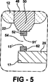
DETAILED DESCRIPTION OF PREFERRED EMBODIMENTS Referring to FIGS. 1-6, the present invention is an electrode for an
図1〜図3を参照すると、この発明に従った電極を有するスパークプラグが、概して10で示されている。スパークプラグ10は、概して12で示された略環状のセラミック絶縁体を含んでおり、それは、特定された誘電強度、高い機械的強度、高い熱伝導性、および優れた耐熱衝撃性を有する酸化アルミニウムまたは他の好適な電気的絶縁材料を含んでいる。絶縁体12は、未加工状態のセラミックパウダからプレス成形され、次に、セラミックパウダを圧縮してガラス化するのに十分高い温度で焼結されてもよい。絶縁体12は外面を有し、それは部分的に露出した上方部分14を含んでいてもよく、それをゴムまたは他の絶縁スパークプラグカバー(図示せず)が包囲して把持し、スパークプラグの端子端部20と点火ワイヤおよびシステム(図示せず)との電気的接続を電気的に絶縁する。露出したマスト部分14は、スパークまたは2次電圧フラッシュオーバーに対する付加された保護を提供し、かつスパークプラグカバーとのマスト部分の把持作用を改良するために、一連のリブ16もしくは他の表面光沢または構成を含んでいてもよい。絶縁体12は略管状または環状の構造をしており、上方の端子端部20と下方のコアノーズ端部22との間で長手方向に延びる中央通路18を含む。中央通路18は一般に断面積が変化しており、通常、端子端部20またはその近傍で最大であり、コアノーズ端部22またはその近傍で最小である。
1-3, a spark plug having an electrode according to the present invention is indicated generally at 10.
導電性の金属シェルは、概して24で示されている。金属シェル24は、コーティングされた、およびコーティングされていないさまざまなスチール合金を含む任意の好適な金属から作られてもよい。シェル24は、絶縁体12の中央および下方部分の外面を包囲してそれと密封係合するようになっている略環状の内面を有しており、また、接地電位に保たれた少なくとも1つの取付けられた接地電極26を含んでいる。接地電極26は、一般に使用されている単一のL字型形式で示されているが、スパークプラグ10の意図された用途に依存して、2つ、3つ、および4つの電極構成を含む、真直ぐな構成、曲がった構成、環状構成、トロコイド型構成、および他の構成の多数の接地電極が代用可能であること、ならびに、特定のスパーキング表面構成を達成するために、電極同士が環状リングおよび他の構造によって接合されたものが使用可能であることが理解されるであろう。接地電極26は、接地電極26と中心電極48との間に位置するスパークギャップ54の近傍にあってスパークギャップ54と部分的に界接するスパーキング端部17上に、1つ以上の接地電極スパーキング表面15を有しており、中心電極48も、関連する中心電極スパーキング表面51を有している。スパークギャップ54は、電極およびそれらのそれぞれのスパーキング端部ならびにスパーキング表面の相対的な配向に依存して、端部ギャップ、側部ギャップ、または表面ギャップ、もしくはそれらの組合せを構成してもよい。接地電極スパーキング表面15および中心電極スパーキング表面51は各々、円、矩形、正方形および他の形状を含む任意の好適な断面形状を有していてもよく、これらの形状は異なっていてもよい。
A conductive metal shell is generally indicated at 24. The metal shell 24 may be made from any suitable metal, including various coated and uncoated steel alloys. The shell 24 has a generally annular inner surface that surrounds and is in sealing engagement with the outer surface of the center and lower portion of the
シェル24はその本体部が略管状または環状であり、絶縁体12の嵌合する下方小肩部11に押圧接触して載るようにされた内部下方圧縮フランジ28を含む。シェル24は通常、上方圧縮フランジ30も含んでおり、それは、絶縁体12の上方大肩部13上に載るよう、組立動作中に曲げられまたは形成されている。シェルはまた、変形可能帯32を含んでいてもよく、それは、シェル24を絶縁体12に対して固定した軸方向位置に保持して、絶縁体12とシェル24との間に半径方向の気密シールを形成するために、上方圧縮フランジ30の変形中または変形後の変形可能帯32の加熱および関連する圧倒的な軸方向圧縮力の印加に応じて、軸方向および半径方向内側に潰れるよう設計され、適合されている。気密シールを完全にし、組立てられたスパークプラグ10の構造的完全性を高めるために、ガスケット、セメント、または他の封止材も、絶縁体12とシェル24との間に挟まれ得る。
The shell 24 has an inner
シェル24には、燃焼室開口部におけるスパークプラグの取外しおよび設置用のツール受け六角形34または他の構成が設けられてもよい。この構成のサイズは、好ましくは、関連する用途についてのこの種の業界基準ツールサイズに準拠している。もちろん、用途によっては、レース用スパークプラグおよび他の用途において知られているようなスパナレンチまたは他の構成を受けるために、六角形以外のツール受け界面、たとえばスロットが必要とされてもよい。金属シェル24の下方部分の、シール座面38のすぐ下に、ねじ切り区間36が形成される。シール座面38は、ガスケット(図示せず)と対になって、スパークプラグ10が載ってシェル24の外面と燃料室開口部のねじ切り孔との間の空間に高温気密を提供する好適な界面を提供してもよい。また、これに代えて、シール座面38は、シェル24の下方部分に沿って位置するテーパ付座面として設計されて、この形式のスパークプラグ座面用の嵌合テーパを有して同様に設計されたシリンダヘッドにおいて精密交差および自己密封設置を提供してもよい。
The shell 24 may be provided with a
導電性の端子スタッド40は、絶縁体12の中央通路18に部分的に配置されており、露出した上部ポスト39から、中央通路18を途中まで降りたところで埋め込まれた底端部41へと長手方向に延びている。上部ポストは、ここに述べたような電気的に絶縁するカバーに通常埋め込まれた点火ワイヤ(図示せず)に繋がっており、スパークギャップ54においてスパークを生成することによりスパークプラグ10を発火させるために必要とされる高電圧電気の、タイミングがとれた放電を受取る。
The conductive
端子スタッド40の底端部41は、複合3層抑制器シールパック43の上層を形成する導電性ガラスシール42内に埋め込まれている。導電性ガラスシール42は、端子スタッド40の底端部を封止して、それを抵抗器層44に電気的に接続するよう機能する。3層抑制器シールパックの中央層を構成するこの抵抗器層44は、電磁干渉(EMI)を減少させることが知られている任意の好適な組成物から作ることができる。使用される点火システムの推奨される設置およびタイプに依存して、そのような抵抗器層44は、より伝統的な抵抗器抑制器として、またはそれに代えて誘導性抑制器として、もしくはそれらの組合せとして機能するよう設計されてもよい。抵抗器層44のすぐ下では、別の導電性ガラスシール46が、抑制器シールパック43の底層または下層を定めており、端子スタッド40および抑制器シールパック43を中心電極48に電気的に接続している。上層42および底層46は、同じ導電性材料から作られてもよく、異なる導電性材料から作られてもよい。ガラスおよび他のシールならびにEMI抑制器の多くの他の構成が周知であり、この発明に従って同様に使用されてもよい。したがって、点火システムからの電荷は、端子スタッド40の底端部から、上層の導電性ガラスシール42、抵抗器層44を通り、下方の導電性ガラスシール層46へと進む。
The
導電性の中心電極48は、中央通路18に部分的に配置されており、下方のガラスシール層46に収容されたそのヘッド49から、接地電極26に近接するそのスパーキング端部50まで長手方向に延びている。中心電極スパーキング表面51はスパーキング端部50上に位置し、接地電極スパーキング表面15と対向して位置しており、それにより、それらの間の空間にスパークギャップ54を形成する。抑制器シールパックは、端子スタッド40と中心電極48とを電気的に相互接続しつつ、同時に、中央通路18を燃焼ガス漏
れから密封し、また、動作中のスパークプラグ10からの無線周波数ノイズ放射を抑制する。図示されているように、中心電極48は好ましくは、そのヘッドとそのスパーキング端部50との間で途切れずに連続的に延びる一体構造である。スパークプラグ10の動作中の中心電極48の極性は、中心電極48が接地電位よりも高いかまたは低い電位を有するよう、正か負であってもよいということは、容易に理解され、またこの発明の範囲内にあるとされるであろう。
A
これはスパークプラグ10の代表的な構造であるが、この発明に従った、絶縁体12、シェル24、および電極26、48を用いた他のスパークプラグ10または点火装置5の構造が可能であることが容易に理解されるであろう。
This is a typical structure of the
好ましくは、中心電極48および接地電極26の双方、しかしながら少なくとも一方は、上述の劣化プロセスに対する耐性が、改良を取入れていない同様の合金配合物のそれを上回って改良されたジルコニウムおよびホウ素の添加によって特別に配合されたNi系ニッケルクロム鉄合金から作製される。この発明が当てはまる合金の一般的な範疇は、特定の高温酸化および腐食プロセスに対する耐性および機械的強度を含むそれらの優れた高温特性に起因して、通常、Ni系超合金と呼ばれる。具体的には、この発明は、インコネル(登録商標)600、ニクロファー(登録商標)7615、フェロクロニン(登録商標)600という商標で販売されている合金を含み、ジルコニウムおよびホウ素を合金配合物に同様に取入れて、これらの合金添加元素を含まない同様の合金配合物を上回る、ここに述べた劣化プロセスに対する改良された耐性をもたらす、金属および合金用統一番号システム(Unified Numbering System:UNS)仕様N06600によって包含される合金などの、固溶体強化されたクロムおよび鉄を含むNi系超合金を含む。この発明の電極は、UNS N06600に定義されたもの以外のUNS名称を有する商業用合金を含むニッケルクロム鉄合金配合物を含み得る、重量で、合計で少なくとも約21.5%のクロムおよび鉄と、0.005〜2.74%のジルコニウムと、0.001〜3.50%のホウ素と、実質的にニッケルである残部とを含む合金を含む、固溶体強化されたNi系ニッケルクロム鉄合金から作られたものを含むと考えられる。また、マンガン、シリコン、アルミニウム、チタン、カルシウム、およびマグネシウムからなる群から選択される少なくとも1つの元素を有するそのような合金を含むとも考えられている。一般に、この改良をもたらすために、添加される少量のジルコニウムおよびホウ素は、同等量のニッケルの代わりに代用されるが、クロムまたは鉄、もしくは上に列挙された別の成分といった他の成分の代わりに代用することも可能である。
Preferably, both the
これらの電極の特に有用な実施例は、重量で、14.5〜25%のクロムと、7〜22%の鉄と、0.2〜0.5%のマンガンと、0.2〜0.5%のシリコンと、0.1〜2.5%のアルミニウムと、0.05〜0.15%のチタンと、合計で0.01〜0.1%のカルシウムおよびマグネシウムと、0.005〜0.5%のジルコニウムと、0.001〜0.01%のホウ素と、実質的にNiである残部とを含む合金を含むNi系ニッケルクロム鉄合金から作られたものを含むと考えられており、0.005〜0.15%の範囲で存在するジルコニウムを有するそのような合金は、ここに述べた高温特性の改良を提供するために特に有用であることが知られている。この発明の合金の残部は実質的にNiであるが、ここに述べた合金添加元素および微量元素を含む、ここに記載された高温特性を著しく低下させない少量の1つ以上の付加的な合金成分を取入れることは除外されない。カルシウムおよびマグネシウムの合計に対する限定は、それらの合計が合金の0.01〜0.1重量%の範囲内にあれば、これらの元素のいずれかが別個に存在していてもよく、または双方とも存在していてもよい、ということを意味している。双方とも存在する場合、各々の量は合金の0.005〜0.05重量%の範囲内にあることが、一般に好ましい。特に明記しない限り、ここに挙げた合金成分の百分率は、合金の重量%である。 Particularly useful examples of these electrodes are 14.5-25% chromium, 7-22% iron, 0.2-0.5% manganese, and 0.2-0. 5% silicon, 0.1-2.5% aluminum, 0.05-0.15% titanium, 0.01-0.1% calcium and magnesium in total, 0.005- It is believed to include those made from Ni-based nickel chromium iron alloys, including alloys containing 0.5% zirconium, 0.001-0.01% boron, and the balance being substantially Ni. Such alloys with zirconium present in the range of 0.005 to 0.15% are known to be particularly useful for providing the high temperature property improvements described herein. The balance of the alloy of the present invention is substantially Ni, but includes a small amount of one or more additional alloy components that do not significantly degrade the high temperature properties described herein, including the alloy additive elements and trace elements described herein. Incorporation is not excluded. The limitation on the total of calcium and magnesium is that any of these elements may be present separately, or both, provided that the total is in the range of 0.01 to 0.1% by weight of the alloy. It means that it may exist. When both are present, it is generally preferred that the amount of each be in the range of 0.005 to 0.05% by weight of the alloy. Unless otherwise stated, the percentages of alloy components listed here are weight percent of the alloy.
ジルコニウムおよびホウ素は通常、Zr/Bの重量比が約5〜150の範囲にあるような量で含まれる。しかしながら、この比率のより好ましい範囲は約50〜100であり、最も好ましい範囲は約70〜80である。ジルコニウムおよびホウ素は、電極合金の他の要件に整合する任意の量で存在していてもよいが、約2.74重量%以下の量のジルコニウムおよび約3.50重量%以下の量のホウ素が、これらの成分にとって好ましい上限であると考えられている。また、ジルコニウムの量はホウ素の量よりも多いことが好ましいと考えられている。固溶体強化されたNi系ニッケルクロム鉄合金では一般に、合金の0.005〜0.5重量%の範囲のジルコニウムおよび合金の0.001〜0.01重量%の範囲のホウ素の使用が特に有用であると考えられている。マンガン、シリコン、アルミニウム、チタン、カルシウム、およびマグネシウムを含む上述の合金組成において、合金の0.005〜0.15重量%の範囲のジルコニウムおよび合金の0.001〜0.01重量%の範囲のホウ素の使用は特に有用であることが知られている。ホウ素およびジルコニウムは粒界強化材として知られている。それらは粒界を分離してそれらを安定化するよう機能して、粒界強度および延性を高め、粒界拡散を遅らせ、電極の動作条件下の環境的および機械的要因によって生じる粒界割れを時間を経過させて(sliding)遅らせ、それにより、高温結晶粒成長を阻止し、高温クリープ、変形、環境亀裂、および応力破断などのさまざまな破壊現象に対するこれらの合金の耐性を高める。ジルコニウムおよびホウ素の添加に関連した性能改良は相乗的であり、すなわち、ジルコニウムかホウ素のいずれかがこれらの合金に別個に添加される際に生じる改良よりも大きい。 Zirconium and boron are usually included in amounts such that the weight ratio of Zr / B is in the range of about 5-150. However, a more preferred range of this ratio is about 50-100 and the most preferred range is about 70-80. Zirconium and boron may be present in any amount consistent with other requirements of the electrode alloy, but an amount of zirconium of up to about 2.74 wt% and boron of up to about 3.50 wt% Are considered to be preferred upper limits for these components. Also, it is considered that the amount of zirconium is preferably larger than the amount of boron. For solid solution reinforced Ni-based nickel chromium iron alloys, it is generally particularly useful to use zirconium in the range of 0.005 to 0.5% by weight of the alloy and boron in the range of 0.001 to 0.01% by weight of the alloy. It is thought that there is. In the above alloy composition comprising manganese, silicon, aluminum, titanium, calcium, and magnesium, zirconium in the range of 0.005 to 0.15% by weight of the alloy and in the range of 0.001 to 0.01% by weight of the alloy. The use of boron is known to be particularly useful. Boron and zirconium are known as grain boundary reinforcements. They function to segregate and stabilize the grain boundaries, increase grain boundary strength and ductility, delay grain boundary diffusion, and reduce grain boundary cracking caused by environmental and mechanical factors under the operating conditions of the electrode. Delaying over time, thereby preventing high temperature grain growth and increasing the resistance of these alloys to various fracture phenomena such as high temperature creep, deformation, environmental cracking, and stress rupture. The performance improvement associated with the addition of zirconium and boron is synergistic, i.e., greater than the improvement that occurs when either zirconium or boron is added separately to these alloys.
特に耐高温酸化性の改良によるこれらの合金の耐劣化性のさらなる改良として、上述の電極合金材料組成物はまた、少なくとも1つの希土類元素を合金添加元素として含んでいてもよい。この用途のために、希土類元素の定義は、反応性遷移金属ではあるものの、希土類合金添加元素の添加によりもたらされるものと同様の、固溶体強化されたこれらのNi系ニッケルクロム鉄合金の改良を同様にもたらすと考えられている、イットリウムおよびハフニウムも含む。より具体的には、希土類元素は、イットリウム、ハフニウム、ランタン、セリウム、およびネオジムからなる群から選択される少なくとも1つの元素を含む。しかしながら、希土類合金添加元素の任意の組合せがこの発明の範囲内にあると理解される。また、より具体的には、全希土類合金添加元素の組成範囲は、好ましくは、合金の0.1〜0.2重量%に制限される。 As a further improvement of the degradation resistance of these alloys, in particular by improving the high temperature oxidation resistance, the electrode alloy material composition described above may also contain at least one rare earth element as an alloying element. For this application, the definition of rare earth elements is similar to the improvement of these Ni-based nickel chromium iron alloys strengthened by solid solution, similar to those brought about by the addition of rare earth alloy additive elements, although they are reactive transition metals. It also includes yttrium and hafnium, which are thought to bring about. More specifically, the rare earth element includes at least one element selected from the group consisting of yttrium, hafnium, lanthanum, cerium, and neodymium. However, it is understood that any combination of rare earth alloy additive elements is within the scope of this invention. More specifically, the composition range of all rare earth alloy additive elements is preferably limited to 0.1 to 0.2% by weight of the alloy.
電極合金材料はまた、微量の他の元素を含んでいてもよい。これらの微量元素は、付随的な不純物元素であってもよい。典型的には、付随的な不純物は、主な合金成分材料を製造するために使用されるプロセス、または電極合金を形成するために使用されるプロセスと関連している。しかしながら、他の電極成分の純度および製造プロセスが制御されるのであれば、これらの微量元素は付随的である必要はなく、それらの有無および相対量が調整されてもよい。微量元素は、コバルト、ニオブ、モリブデン、銅、炭素、鉛、リン、および硫黄を任意の組合せで含んでいてもよい。この発明の電極合金材料は典型的には、これらの元素のうちの少なくとも1つを含み、それらの総数は典型的には、記載された成分を生成するために使用される源および製造方法と関連している。コバルト、ニオブ、モリブデン、銅、および炭素を含む、これらの元素のうちのいくつかは、ここに述べた高温特性の改良に対して中立的〜若干プラスの効果を有する場合があるが、一方、鉛、リン、および硫黄を含むその他は、それらに対して若干マイナスの効果を有する場合がある。これらの元素が合金内に存在する限り、それらがその高温特性に対してプラスの効果を有するか、またはマイナスの影響を有するかに関わらず、それらの量を、Ni系ニッケルクロム鉄合金の重量で、コバルトについては最大0.1%、ニオブについては最大0.05%、モリブデンについては最大0.05%、銅については最大0.01%、炭素については最大0.01%、鉛については最大0.005%、リンについては最大0.005%、硫黄については最大0.005%に制限することが好ましい。 The electrode alloy material may also contain trace amounts of other elements. These trace elements may be incidental impurity elements. Typically, incidental impurities are associated with the process used to produce the main alloy component material, or the process used to form the electrode alloy. However, as long as the purity and manufacturing process of other electrode components are controlled, these trace elements do not have to be incidental, and their presence and relative amount may be adjusted. The trace element may contain cobalt, niobium, molybdenum, copper, carbon, lead, phosphorus, and sulfur in any combination. The electrode alloy material of the present invention typically includes at least one of these elements, the total number of which typically includes the sources and manufacturing methods used to produce the components described. Related. Some of these elements, including cobalt, niobium, molybdenum, copper, and carbon, may have a neutral to slightly positive effect on improving the high temperature properties described here, while Others including lead, phosphorus, and sulfur may have some negative effects on them. As long as these elements are present in the alloy, their amount is determined by the weight of the Ni-based nickel chrome iron alloy, regardless of whether they have a positive or negative effect on their high temperature properties. Up to 0.1% for cobalt, up to 0.05% for niobium, up to 0.05% for molybdenum, up to 0.01% for copper, up to 0.01% for carbon, It is preferable to limit to a maximum of 0.005%, a maximum of 0.005% for phosphorus, and a maximum of 0.005% for sulfur.
述べてきたようなNi系ニッケルクロム鉄合金組成物から作られたスパークプラグ接地電極26および中心電極48は、酸化、硫化、および関連する腐食磨耗に対する耐性が改良されており、かつ、内燃エンジンの燃焼室の極度に悪い環境における熱機械応力に関連した亀裂および破壊に対する耐性が改良されている。
Spark
図3に示すように、代替的な電極構成では、接地電極26および中心電極48のいずれか一方または双方に、銅または銀、もしくはそれらのうちのいずれかのさまざまな合金といった高い熱伝導性(たとえば≧250W/M*°K)を有する材料から作られた熱伝導性コア27,49がそれぞれ設けられ得る。高い熱伝導性のコアはヒートシンクとして機能して、スパークギャップ54領域から熱を引き離すのを助長し、それにより、この領域における電極の動作温度を低下させ、ここに述べたそれらの性能および劣化プロセスに対する耐性をさらに改良する。
As shown in FIG. 3, in an alternative electrode configuration, one or both of the
図4〜図6に示すように、スパークプラグ10はまた、接地電極26または中心電極48のいずれかもしくは双方のスパーキング端部上に、述べてきた改良されたスパーク性能または劣化プロセスに対する耐性のいずれかもしくは双方を有する異なる高温材料でできた発火チップ62、52をそれぞれ取入れてもよい。これは、あらゆる種類の貴金属および非貴金属発火チップを含んでいてもよい。中心電極48の発火チップ52はこの電極のスパーキング端部50上に位置しており、スパーキング表面51′を有する。接地電極26の発火チップ62はこの電極のスパーキング端部17上に位置しており、スパーキング表面15′を有する。発火チップ52、62は、使用時、スパークギャップ54を横切るように電子を放出するためのスパーキング表面51′、15′をそれぞれ含む。中心電極48用の発火チップ52および接地電極26用の発火チップ62は各々、抵抗溶接、レーザ溶接、またはそれらの組合せといったさまざまな組合せによるさまざまなパッド状、ワイヤ状、またはリベット状の発火チップの形成および取付け、もしくはその逆を含む、多数の公知の手法のうちのいずれかに従って、作られて接合され得る。発火チップ52、62は、金、またはAu−40Pd(重量%)合金などのAu−Pd合金を含む金合金から作られてもよい。発火チップ52、62はまた、白金、イリジウム、ロジウム、パラジウム、ルテニウム、およびレニウム、ならびに任意に組合わされたそれらの合金のさまざまな組合せを含む白金族金属の公知の純金属または合金のうちのいずれかから作られてもよい。この用途のために、レニウムも、白金族金属のうちのいくつかと同様のその高い融点および他の高温特性に基づいて、白金族金属の定義内に含まれる。発火チップ52、62で使用するための追加の合金元素は、ニッケル、クロム、鉄、マンガン、銅、アルミニウム、コバルト、ジルコニウム、タングステンと、イットリウム、ハフニウム、ランタン、セリウム、およびネオジムを含む希土類元素とを含んでいてもよいが、それらに限定されない。実際、燃焼環境における好適なスパーク侵食腐食性能を提供するあらゆる材料が、発火チップ52、62としての使用にとって好適であり得る。発火チップ52、62はまた、W−Ni合金、W−Cu合金、およびW−Ni−Cu合金を含むさまざまなタングステン合金から作られてもよい。
As shown in FIGS. 4-6, the
このNi系ニッケルクロム鉄電極材料はまた、それらで作られた電極体に、発火チップ52、62または他の構成が溶接されている場合にも有利である。それは、高温での溶接部の強度、耐久性、および耐破壊性の改良をもたらす。このNi系ニッケルクロム鉄電極材料は、スパークプラグ10用の接地電極26および/または中心電極48という特定の用途での使用について説明されてきたが、発明された材料の、高温酸化および硫化に対する優れた耐性、高温での機械的強度、および、熱機械的に誘発された応力による溶接取付部、特にさまざまな発火チップ構成に関連する溶接取付部の亀裂および破壊に対する耐性の改良により、他の点火装置用電極へのこの合金の他の使用および用途が当業者により理解される、ということが理解されるであろう。
This Ni-based nickel chrome iron electrode material is also advantageous when the
明らかに、この発明の多くの修正および変更が、上述の教示に鑑みて可能である。したがって、添付された特許請求の範囲内において、この発明が具体的な記載以外の態様で実践され得ることが理解されるはずである。 Obviously, many modifications and variations of the present invention are possible in light of the above teachings. It is therefore to be understood that within the scope of the appended claims, the invention may be practiced otherwise than as specifically described.
Claims (4)
14.5〜25%のクロムと、
7〜22%の鉄と、
0.2〜0.5%のマンガンと、
0.2〜0.5%のシリコンと、
0.1〜2.5%のアルミニウムと、
0.05〜0.15%のチタンと、
合計で0.01〜0.1%のカルシウムおよびマグネシウムと、
0.005〜0.5%のジルコニウムと、
0.001〜0.01%のホウ素と、
Niおよび付随的な不純物である残部とからなる合金を含む、電極。An electrode for an ignition device, said electrode being essentially by weight,
14.5-25% chromium,
7-22% iron,
0.2-0.5% manganese,
0.2-0.5% silicon,
0.1-2.5% aluminum;
0.05-0.15% titanium,
A total of 0.01-0.1% calcium and magnesium;
0.005 to 0.5% zirconium;
0.001 to 0.01% boron,
An electrode comprising an alloy consisting of Ni and the balance being an incidental impurity.
略環状のセラミック絶縁体と、
前記セラミック絶縁体の少なくとも一部を包囲する導電性シェルと、
端子端部と中心電極スパーキング表面を有するスパーキング端部とを有する、前記セラミック絶縁体内に配置された中心電極と、
前記中心電極スパーキング表面に近接して位置する接地電極スパーキング表面を有する、前記シェルに動作可能に取付けられた接地電極とを含み、前記中心電極スパーキング表面および前記接地電極スパーキング表面は、それらの間にスパークギャップを規定しており、
前記中心電極または前記接地電極のうちの少なくとも1つは前記電極である、請求項1に記載の電極。The ignition device is a spark plug;
A substantially annular ceramic insulator;
A conductive shell surrounding at least a portion of the ceramic insulator;
A center electrode disposed within the ceramic insulator having a terminal end and a sparking end having a center electrode sparking surface;
A ground electrode operably attached to the shell having a ground electrode sparking surface positioned proximate to the center electrode sparking surface, the center electrode sparking surface and the ground electrode sparking surface comprising: A spark gap is defined between them,
The electrode according to claim 1 , wherein at least one of the center electrode or the ground electrode is the electrode.
Applications Claiming Priority (5)
| Application Number | Priority Date | Filing Date | Title |
|---|---|---|---|
| US81484206P | 2006-06-19 | 2006-06-19 | |
| US60/814,842 | 2006-06-19 | ||
| US11/764,528 US7823556B2 (en) | 2006-06-19 | 2007-06-18 | Electrode for an ignition device |
| US11/764,528 | 2007-06-18 | ||
| PCT/US2007/071507 WO2007149826A2 (en) | 2006-06-19 | 2007-06-19 | Electrode for an ignition device |
Publications (3)
| Publication Number | Publication Date |
|---|---|
| JP2009541942A JP2009541942A (en) | 2009-11-26 |
| JP2009541942A5 JP2009541942A5 (en) | 2010-07-29 |
| JP5200247B2 true JP5200247B2 (en) | 2013-06-05 |
Family
ID=38834294
Family Applications (1)
| Application Number | Title | Priority Date | Filing Date |
|---|---|---|---|
| JP2009516665A Expired - Fee Related JP5200247B2 (en) | 2006-06-19 | 2007-06-19 | Ignition electrode |
Country Status (7)
| Country | Link |
|---|---|
| US (1) | US7823556B2 (en) |
| EP (1) | EP2035592A4 (en) |
| JP (1) | JP5200247B2 (en) |
| KR (1) | KR20090033229A (en) |
| CN (1) | CN101501229B (en) |
| BR (1) | BRPI0713676A2 (en) |
| WO (1) | WO2007149826A2 (en) |
Families Citing this family (37)
| Publication number | Priority date | Publication date | Assignee | Title |
|---|---|---|---|---|
| IL130818A (en) | 1999-07-06 | 2005-07-25 | Intercure Ltd | Interventive-diagnostic device |
| US20080308057A1 (en) * | 2007-06-18 | 2008-12-18 | Lykowski James D | Electrode for an Ignition Device |
| JP5261631B2 (en) | 2007-07-12 | 2013-08-14 | イマジニアリング株式会社 | Ignition or plasma generator |
| JP4847992B2 (en) * | 2007-08-23 | 2011-12-28 | 日本特殊陶業株式会社 | Spark plug for internal combustion engine |
| DE102007040722A1 (en) * | 2007-08-29 | 2009-03-05 | Robert Bosch Gmbh | Spark plug electrode made of improved electrode material |
| US20090072694A1 (en) * | 2007-09-17 | 2009-03-19 | Steigleman Jr Robert Lee | Sparkplug having improved heat removal capabilities and method to recycle used sparkplugs |
| WO2009081562A1 (en) * | 2007-12-20 | 2009-07-02 | Ngk Spark Plug Co., Ltd. | Spark plug and process for producing the spark plug |
| US20100264801A1 (en) * | 2007-12-20 | 2010-10-21 | Tomoo Tanaka | Spark plug and process for producing the spark plug |
| US7969078B2 (en) * | 2008-05-19 | 2011-06-28 | Federal Mogul Ignition Company | Spark ignition device for an internal combustion engine and sparking tip therefor |
| US8614541B2 (en) * | 2008-08-28 | 2013-12-24 | Federal-Mogul Ignition Company | Spark plug with ceramic electrode tip |
| US9219351B2 (en) | 2008-08-28 | 2015-12-22 | Federal-Mogul Ignition Company | Spark plug with ceramic electrode tip |
| EP2325960B1 (en) * | 2008-09-09 | 2017-05-31 | NGK Spark Plug Co., Ltd. | Spark plug |
| JP5041561B2 (en) * | 2008-09-24 | 2012-10-03 | 日本特殊陶業株式会社 | Spark plug |
| EP2465173B1 (en) * | 2009-08-12 | 2018-05-16 | Federal-Mogul Ignition Company | Spark plug including electrodes with low swelling rate and high corrosion resistance |
| CN102859817A (en) | 2010-04-13 | 2013-01-02 | 费德罗-莫格尔点火公司 | Igniter including a corona enhancing electrode tip |
| EP2560255B1 (en) * | 2010-04-16 | 2019-07-10 | NGK Spark Plug Co., Ltd. | Spark plug for internal combustion engine and method of manufacturing spark plug |
| CN101851714A (en) * | 2010-05-27 | 2010-10-06 | 江苏新华合金电器有限公司 | Shockproof strip end-plate material of vapor generator of nuclear power plant and preparation method thereof |
| KR101435734B1 (en) * | 2010-06-02 | 2014-08-28 | 니혼도꾸슈도교 가부시키가이샤 | Spark plug |
| JP5301035B2 (en) | 2010-12-24 | 2013-09-25 | 日本特殊陶業株式会社 | Spark plug |
| DE102011007496A1 (en) * | 2011-04-15 | 2012-10-18 | Robert Bosch Gmbh | A spark plug electrode material and spark plug, and a method of manufacturing the spark plug electrode material and an electrode for the spark plug |
| DE102011077893A1 (en) * | 2011-06-21 | 2012-12-27 | Robert Bosch Gmbh | Use of a hot gas corrosion resistant ductile alloy |
| WO2013028603A1 (en) | 2011-08-19 | 2013-02-28 | Federal-Mogul Ignition Company | Corona igniter including temperature control features |
| DE102012015828B4 (en) * | 2012-08-10 | 2014-09-18 | VDM Metals GmbH | Use of a nickel-chromium-iron-aluminum alloy with good processability |
| KR101625349B1 (en) * | 2013-01-08 | 2016-05-27 | 니뽄 도쿠슈 도교 가부시키가이샤 | Electrode material and spark plug |
| US9083156B2 (en) | 2013-02-15 | 2015-07-14 | Federal-Mogul Ignition Company | Electrode core material for spark plugs |
| CN103451478B (en) * | 2013-09-02 | 2015-10-21 | 山东大学 | A kind of nickel base superalloy, its preparation method and the application in sparking-plug electrode |
| CN103746295A (en) * | 2013-12-27 | 2014-04-23 | 黄忠波 | Electrode material for sparking plug |
| CN105385899A (en) * | 2015-12-02 | 2016-03-09 | 苏州龙腾万里化工科技有限公司 | Resistance alloy for grinder sensor element |
| CN109312384B (en) | 2016-06-15 | 2022-12-30 | 伊士曼化工公司 | Physical vapor deposition biosensor assembly |
| JP6335979B2 (en) * | 2016-07-15 | 2018-05-30 | 日本特殊陶業株式会社 | Spark plug |
| JP7096816B2 (en) | 2016-09-16 | 2022-07-06 | イーストマン ケミカル カンパニー | Biosensor electrode manufactured by physical vapor deposition |
| US11630075B2 (en) | 2016-09-16 | 2023-04-18 | Eastman Chemical Company | Biosensor electrodes prepared by physical vapor deposition |
| KR102646492B1 (en) | 2017-06-22 | 2024-03-12 | 이스트만 케미칼 컴파니 | Physically deposited electrodes for electrochemical sensors |
| CN110055440A (en) * | 2019-05-29 | 2019-07-26 | 南京达迈科技实业有限公司 | A kind of multicomponent alloy silk and preparation method thereof for spark plug |
| CN114342196B (en) * | 2019-09-06 | 2022-09-27 | 联邦-富豪燃气有限责任公司 | Electrode material for spark plug |
| CN113265563B (en) * | 2021-05-06 | 2022-04-29 | 中国联合重型燃气轮机技术有限公司 | Ni high-temperature alloy with good heat corrosion resistance and preparation method thereof |
| JP7429725B2 (en) | 2022-02-18 | 2024-02-08 | 日本特殊陶業株式会社 | Spark plug main metal fittings and spark plugs |
Family Cites Families (30)
| Publication number | Priority date | Publication date | Assignee | Title |
|---|---|---|---|---|
| US2482580A (en) * | 1949-09-20 | Method of making fired vitreous | ||
| US3907552A (en) * | 1971-10-12 | 1975-09-23 | Teledyne Inc | Nickel base alloys of improved properties |
| US4078951A (en) * | 1976-03-31 | 1978-03-14 | University Patents, Inc. | Method of improving fatigue life of cast nickel based superalloys and composition |
| US4439498A (en) * | 1976-08-24 | 1984-03-27 | The International Nickel Company, Inc. | Corrosion resistant stainless steel covered electrode |
| US4415530A (en) * | 1980-11-10 | 1983-11-15 | Huntington Alloys, Inc. | Nickel-base welding alloy |
| CH657380A5 (en) * | 1981-09-04 | 1986-08-29 | Mitsubishi Metal Corp | AT INCREASED TEMPERATURES, HEAT-RESISTANT, WEAR-RESISTANT AND TOE ALLOY ON NICKEL BASE. |
| JPS60211028A (en) * | 1984-04-03 | 1985-10-23 | Daido Steel Co Ltd | Alloy for exhaust valve |
| US4536215A (en) * | 1984-12-10 | 1985-08-20 | Gte Products Corporation | Boron addition to alloys |
| US4639576A (en) * | 1985-03-22 | 1987-01-27 | Inco Alloys International, Inc. | Welding electrode |
| US4784830A (en) * | 1986-07-03 | 1988-11-15 | Inco Alloys International, Inc. | High nickel chromium alloy |
| US4742265A (en) * | 1986-11-12 | 1988-05-03 | Ford Motor Company | Spark plug center electrode of alloy material including aluminum and chromium |
| JPS63312939A (en) * | 1987-06-17 | 1988-12-21 | Sumitomo Electric Ind Ltd | Electrode material for ignition plug |
| US4844864A (en) * | 1988-04-27 | 1989-07-04 | Carpenter Technology Corporation | Precipitation hardenable, nickel-base alloy |
| US4881913A (en) * | 1988-06-16 | 1989-11-21 | General Motors Corporation | Extended life spark plug/igniter |
| JPH07268522A (en) * | 1994-03-31 | 1995-10-17 | Hitachi Metals Ltd | Electrode material for spark plug excellent in high temperature strength |
| DE19524234C1 (en) * | 1995-07-04 | 1997-08-28 | Krupp Vdm Gmbh | Kneadable nickel alloy |
| FR2786419B1 (en) * | 1998-12-01 | 2001-01-05 | Imphy Sa | NICKEL BASED ALLOY WELDING ELECTRODE AND CORRESPONDING ALLOY |
| US5997809A (en) * | 1998-12-08 | 1999-12-07 | Inco Alloys International, Inc. | Alloys for high temperature service in aggressive environments |
| US6287398B1 (en) * | 1998-12-09 | 2001-09-11 | Inco Alloys International, Inc. | High strength alloy tailored for high temperature mixed-oxidant environments |
| JP3625262B2 (en) | 1999-03-19 | 2005-03-02 | 日立金属株式会社 | Spark plug electrode material with excellent high-temperature oxidation resistance and hot workability |
| US6242113B1 (en) * | 1999-06-10 | 2001-06-05 | Inco Alloys International, Inc. | Welding alloy and articles for use in welding, weldments and methods for producing weldments |
| JP3931003B2 (en) * | 1999-08-26 | 2007-06-13 | 日本特殊陶業株式会社 | Manufacturing method of spark plug |
| DE10025108A1 (en) * | 2000-05-20 | 2001-11-29 | Forschungszentrum Juelich Gmbh | High temperature material |
| JP2002235138A (en) * | 2001-02-05 | 2002-08-23 | Mitsubishi Materials Corp | Spark plug electrode material having excellent spark consumption resistance |
| JP4073636B2 (en) * | 2001-02-28 | 2008-04-09 | 日本特殊陶業株式会社 | Spark plug and manufacturing method thereof |
| JP4171206B2 (en) * | 2001-03-16 | 2008-10-22 | 株式会社デンソー | Spark plug and manufacturing method thereof |
| JP2003142227A (en) * | 2001-08-22 | 2003-05-16 | Denso Corp | Spark plug |
| DE10222262A1 (en) * | 2002-05-18 | 2003-11-27 | Bosch Gmbh Robert | Nickel alloy for an ignition device used in a vehicle contains chromium, aluminum and silicon |
| AT413904B (en) * | 2003-09-19 | 2006-07-15 | Ge Jenbacher Ag | SPARK PLUG |
| JP4706441B2 (en) * | 2004-11-04 | 2011-06-22 | 日立金属株式会社 | Spark plug electrode material |
-
2007
- 2007-06-18 US US11/764,528 patent/US7823556B2/en active Active
- 2007-06-19 BR BRPI0713676-5A patent/BRPI0713676A2/en not_active IP Right Cessation
- 2007-06-19 CN CN2007800293706A patent/CN101501229B/en not_active Expired - Fee Related
- 2007-06-19 JP JP2009516665A patent/JP5200247B2/en not_active Expired - Fee Related
- 2007-06-19 KR KR1020097000958A patent/KR20090033229A/en not_active Application Discontinuation
- 2007-06-19 EP EP07798724A patent/EP2035592A4/en not_active Withdrawn
- 2007-06-19 WO PCT/US2007/071507 patent/WO2007149826A2/en active Application Filing
Also Published As
| Publication number | Publication date |
|---|---|
| BRPI0713676A2 (en) | 2012-10-23 |
| US7823556B2 (en) | 2010-11-02 |
| EP2035592A2 (en) | 2009-03-18 |
| CN101501229B (en) | 2011-06-08 |
| WO2007149826A2 (en) | 2007-12-27 |
| KR20090033229A (en) | 2009-04-01 |
| US20070290591A1 (en) | 2007-12-20 |
| EP2035592A4 (en) | 2011-12-21 |
| WO2007149826A3 (en) | 2008-12-24 |
| JP2009541942A (en) | 2009-11-26 |
| CN101501229A (en) | 2009-08-05 |
Similar Documents
| Publication | Publication Date | Title |
|---|---|---|
| JP5200247B2 (en) | Ignition electrode | |
| EP2168217B1 (en) | Electrode for an ignition device | |
| US9027524B2 (en) | Spark plug for internal combustion engine and method of manufacturing the same | |
| US20070290593A1 (en) | Spark Plug With Fine Wire Ground Electrode | |
| US7816845B2 (en) | Ceramic electrode and ignition device therewith | |
| WO2009039478A2 (en) | Spark plug structure for improved ignitability | |
| JP2009541943A (en) | Small diameter / long reach spark plug with hemispherical spark tip with rim | |
| US7795791B2 (en) | One piece shell high thread spark plug | |
| US20120074829A1 (en) | Alloys for spark ignition device electrode spark surfaces | |
| KR20090035593A (en) | One piece shell high thread spark plug | |
| US20100052500A1 (en) | Spark plug and methods of construction thereof | |
| JP4944433B2 (en) | Spark plug | |
| WO2008082716A2 (en) | Ignition device electrode composition | |
| US20220302682A1 (en) | Electrode material for a spark plug | |
| JP2009140674A (en) | Spark plug for gas engine |
Legal Events
| Date | Code | Title | Description |
|---|---|---|---|
| A521 | Written amendment |
Free format text: JAPANESE INTERMEDIATE CODE: A523 Effective date: 20100611 |
|
| A621 | Written request for application examination |
Free format text: JAPANESE INTERMEDIATE CODE: A621 Effective date: 20100611 |
|
| A977 | Report on retrieval |
Free format text: JAPANESE INTERMEDIATE CODE: A971007 Effective date: 20120309 |
|
| A131 | Notification of reasons for refusal |
Free format text: JAPANESE INTERMEDIATE CODE: A131 Effective date: 20120321 |
|
| A521 | Written amendment |
Free format text: JAPANESE INTERMEDIATE CODE: A523 Effective date: 20120613 |
|
| A02 | Decision of refusal |
Free format text: JAPANESE INTERMEDIATE CODE: A02 Effective date: 20120828 |
|
| A521 | Written amendment |
Free format text: JAPANESE INTERMEDIATE CODE: A523 Effective date: 20121210 |
|
| A911 | Transfer to examiner for re-examination before appeal (zenchi) |
Free format text: JAPANESE INTERMEDIATE CODE: A911 Effective date: 20121217 |
|
| TRDD | Decision of grant or rejection written | ||
| A01 | Written decision to grant a patent or to grant a registration (utility model) |
Free format text: JAPANESE INTERMEDIATE CODE: A01 Effective date: 20130115 |
|
| A61 | First payment of annual fees (during grant procedure) |
Free format text: JAPANESE INTERMEDIATE CODE: A61 Effective date: 20130117 |
|
| R150 | Certificate of patent or registration of utility model |
Free format text: JAPANESE INTERMEDIATE CODE: R150 |
|
| FPAY | Renewal fee payment (event date is renewal date of database) |
Free format text: PAYMENT UNTIL: 20160222 Year of fee payment: 3 |
|
| LAPS | Cancellation because of no payment of annual fees |