JP5199262B2 - Improved membrane module - Google Patents
Improved membrane module Download PDFInfo
- Publication number
- JP5199262B2 JP5199262B2 JP2009529257A JP2009529257A JP5199262B2 JP 5199262 B2 JP5199262 B2 JP 5199262B2 JP 2009529257 A JP2009529257 A JP 2009529257A JP 2009529257 A JP2009529257 A JP 2009529257A JP 5199262 B2 JP5199262 B2 JP 5199262B2
- Authority
- JP
- Japan
- Prior art keywords
- hollow fiber
- module
- fiber membrane
- membrane module
- sweep
- Prior art date
- Legal status (The legal status is an assumption and is not a legal conclusion. Google has not performed a legal analysis and makes no representation as to the accuracy of the status listed.)
- Expired - Fee Related
Links
- 239000012528 membrane Substances 0.000 title claims description 69
- 239000000835 fiber Substances 0.000 claims description 84
- 239000012510 hollow fiber Substances 0.000 claims description 62
- 238000004804 winding Methods 0.000 claims description 19
- 239000000463 material Substances 0.000 claims description 18
- 238000012856 packing Methods 0.000 claims description 6
- 230000004323 axial length Effects 0.000 claims description 5
- 238000004382 potting Methods 0.000 claims description 5
- 238000007789 sealing Methods 0.000 claims description 5
- 230000007423 decrease Effects 0.000 claims description 4
- 230000004888 barrier function Effects 0.000 claims 6
- 238000000034 method Methods 0.000 description 12
- 238000013461 design Methods 0.000 description 9
- XLYOFNOQVPJJNP-UHFFFAOYSA-N water Chemical compound O XLYOFNOQVPJJNP-UHFFFAOYSA-N 0.000 description 6
- 230000018044 dehydration Effects 0.000 description 4
- 238000006297 dehydration reaction Methods 0.000 description 4
- 238000012546 transfer Methods 0.000 description 4
- 238000001035 drying Methods 0.000 description 3
- 230000035515 penetration Effects 0.000 description 3
- 230000007812 deficiency Effects 0.000 description 2
- 239000006260 foam Substances 0.000 description 2
- 238000004519 manufacturing process Methods 0.000 description 2
- 238000009828 non-uniform distribution Methods 0.000 description 2
- 239000000047 product Substances 0.000 description 2
- 239000002994 raw material Substances 0.000 description 2
- 238000000926 separation method Methods 0.000 description 2
- 239000002904 solvent Substances 0.000 description 2
- 229920005830 Polyurethane Foam Polymers 0.000 description 1
- 239000000853 adhesive Substances 0.000 description 1
- 230000001070 adhesive effect Effects 0.000 description 1
- 239000000443 aerosol Substances 0.000 description 1
- 238000013459 approach Methods 0.000 description 1
- 239000000701 coagulant Substances 0.000 description 1
- 238000004581 coalescence Methods 0.000 description 1
- 239000002131 composite material Substances 0.000 description 1
- 230000001010 compromised effect Effects 0.000 description 1
- 238000005520 cutting process Methods 0.000 description 1
- 238000009826 distribution Methods 0.000 description 1
- 239000012530 fluid Substances 0.000 description 1
- 229920001477 hydrophilic polymer Polymers 0.000 description 1
- 238000002347 injection Methods 0.000 description 1
- 239000007924 injection Substances 0.000 description 1
- 230000003071 parasitic effect Effects 0.000 description 1
- 239000012466 permeate Substances 0.000 description 1
- 229920000642 polymer Polymers 0.000 description 1
- 239000011496 polyurethane foam Substances 0.000 description 1
- 239000011148 porous material Substances 0.000 description 1
- 239000007787 solid Substances 0.000 description 1
- 239000000243 solution Substances 0.000 description 1
- 239000000126 substance Substances 0.000 description 1
- 238000003466 welding Methods 0.000 description 1
Images


Classifications
-
- B—PERFORMING OPERATIONS; TRANSPORTING
- B01—PHYSICAL OR CHEMICAL PROCESSES OR APPARATUS IN GENERAL
- B01D—SEPARATION
- B01D53/00—Separation of gases or vapours; Recovering vapours of volatile solvents from gases; Chemical or biological purification of waste gases, e.g. engine exhaust gases, smoke, fumes, flue gases, aerosols
- B01D53/26—Drying gases or vapours
- B01D53/268—Drying gases or vapours by diffusion
-
- B—PERFORMING OPERATIONS; TRANSPORTING
- B01—PHYSICAL OR CHEMICAL PROCESSES OR APPARATUS IN GENERAL
- B01D—SEPARATION
- B01D53/00—Separation of gases or vapours; Recovering vapours of volatile solvents from gases; Chemical or biological purification of waste gases, e.g. engine exhaust gases, smoke, fumes, flue gases, aerosols
- B01D53/22—Separation of gases or vapours; Recovering vapours of volatile solvents from gases; Chemical or biological purification of waste gases, e.g. engine exhaust gases, smoke, fumes, flue gases, aerosols by diffusion
- B01D53/228—Separation of gases or vapours; Recovering vapours of volatile solvents from gases; Chemical or biological purification of waste gases, e.g. engine exhaust gases, smoke, fumes, flue gases, aerosols by diffusion characterised by specific membranes
-
- B—PERFORMING OPERATIONS; TRANSPORTING
- B01—PHYSICAL OR CHEMICAL PROCESSES OR APPARATUS IN GENERAL
- B01D—SEPARATION
- B01D63/00—Apparatus in general for separation processes using semi-permeable membranes
- B01D63/02—Hollow fibre modules
- B01D63/021—Manufacturing thereof
- B01D63/0233—Manufacturing thereof forming the bundle
-
- B—PERFORMING OPERATIONS; TRANSPORTING
- B01—PHYSICAL OR CHEMICAL PROCESSES OR APPARATUS IN GENERAL
- B01D—SEPARATION
- B01D63/00—Apparatus in general for separation processes using semi-permeable membranes
- B01D63/02—Hollow fibre modules
- B01D63/025—Bobbin units
-
- B—PERFORMING OPERATIONS; TRANSPORTING
- B01—PHYSICAL OR CHEMICAL PROCESSES OR APPARATUS IN GENERAL
- B01D—SEPARATION
- B01D65/00—Accessories or auxiliary operations, in general, for separation processes or apparatus using semi-permeable membranes
- B01D65/003—Membrane bonding or sealing
-
- B—PERFORMING OPERATIONS; TRANSPORTING
- B01—PHYSICAL OR CHEMICAL PROCESSES OR APPARATUS IN GENERAL
- B01D—SEPARATION
- B01D2257/00—Components to be removed
- B01D2257/80—Water
-
- B—PERFORMING OPERATIONS; TRANSPORTING
- B01—PHYSICAL OR CHEMICAL PROCESSES OR APPARATUS IN GENERAL
- B01D—SEPARATION
- B01D2311/00—Details relating to membrane separation process operations and control
- B01D2311/13—Use of sweep gas
-
- B—PERFORMING OPERATIONS; TRANSPORTING
- B01—PHYSICAL OR CHEMICAL PROCESSES OR APPARATUS IN GENERAL
- B01D—SEPARATION
- B01D2313/00—Details relating to membrane modules or apparatus
- B01D2313/23—Specific membrane protectors, e.g. sleeves or screens
Landscapes
- Chemical & Material Sciences (AREA)
- Chemical Kinetics & Catalysis (AREA)
- Engineering & Computer Science (AREA)
- Analytical Chemistry (AREA)
- General Chemical & Material Sciences (AREA)
- Oil, Petroleum & Natural Gas (AREA)
- Manufacturing & Machinery (AREA)
- Separation Using Semi-Permeable Membranes (AREA)
- Drying Of Gases (AREA)
Description
本発明は、ガス分離またはガス移送に用いるための中空繊維膜モジュールに関し、より詳細には、ガス流からの水蒸気の除去のための、または1つのガス流からもう1つのガス流への水蒸気の移動のための、改良されたモジュールデザインに関する。 The present invention relates to a hollow fiber membrane module for use in gas separation or gas transfer, and more particularly for the removal of water vapor from a gas stream or from one gas stream to another gas stream. It relates to an improved modular design for mobility.
ガス流の脱水及び1つのガス流から別のガス流への水分の移動のために、水浸透性の中空繊維膜モジュールが商業的に使用されてきた。特許文献1及び2にはガスの脱水に適した膜モジュールが開示されており、両文献は引用を以て本明細書の一部となす。特許文献3にはガスの乾燥または加湿のための膜が開示されている。本発明の特徴を説明するために、ボアサイドフィード型(bore-side feed)ガス脱水モジュールのみを考えるが、この膜モジュールのデザインコンセプトは、前述のガス分離及びガス移送の用途に適用可能である。これらの膜モジュールでは、除去される水分を含む供給ガスが、中空繊維膜のルーメンを通って流れる。供給ガスが膜ルーメンを通って流れるときに、水分が水浸透性膜を透過してモジュールのシェルサイドへ拡散する。このプロセスを維持するために、モジュールのシェルサイドに乾性ガスを注入して、浸透した水蒸気を一掃(スウィープ・アウェイ)する。多くの場合、この乾性スウィープガスは、膜モジュールによって生成される乾性ガスから得られるが、他の原料が用いられることもある。
Water permeable hollow fiber membrane modules have been used commercially for the dehydration of gas streams and the transfer of moisture from one gas stream to another.
理想的なモジュールでは、各繊維のルーメンが同量のガスフローを受容するのみならず、繊維の外側付近でスウィープガスが均一に分布され、各繊維には同量のスウィープガスが接触する。しかし、実際には、ある程度のスウィープガスの不均等分布が生じ、これが性能を低下させる。この問題を克服するために、追加の膜または追加のスウィープガスフローのいずれかを用いなければならないが、いずれにしてもプロセスのコストが増す。それゆえ、膜モジュールデザイナーは、スウィープフローの不均等分布を最小にし、モジュール性能を最大にするための新たな膜モジュールデザインを絶えず開発しているのである。 In an ideal module, not only does the lumen of each fiber receive the same amount of gas flow, but the sweep gas is evenly distributed near the outside of the fiber and the same amount of sweep gas contacts each fiber. However, in practice, a certain amount of sweep gas non-uniform distribution occurs, which reduces performance. To overcome this problem, either an additional membrane or an additional sweep gas flow must be used, but in any case increases the cost of the process. Therefore, membrane module designers are constantly developing new membrane module designs to minimize the uneven distribution of sweep flow and maximize module performance.
特許文献4には、芯部の周りに螺旋状に巻かれた中空繊維群を用いてシェルサイドフローを向上させた膜モジュールデザインが開示されている。しかし、特許文献4は、このアプローチの限界は繊維群が実質的に均一長でなければならないことであることを教示しており、実質的に均一長を「浸透装置セルの中空繊維群の有効長は、約20パーセント未満の差で変化することになる」(カラム6、第41〜44行)と定義している。 Patent Document 4 discloses a membrane module design in which shell side flow is improved using a group of hollow fibers wound spirally around a core portion. However, U.S. Patent No. 6,047,096 teaches that the limitation of this approach is that the fibers must be of substantially uniform length, and the substantially uniform length is referred to as "effectiveness of the hollow fibers of the permeator cell. The length will vary with a difference of less than about 20 percent "(column 6, lines 41-44).
膜モジュールデザインに関連する性能面に加えて、膜モジュールは、種々の用途に対して必要な構造的完全性を有していなければならない。ガス乾燥用途では、ガスは高圧であり、数百psigを超える場合がある。この圧力による力が管板の表面に加えられるので、これらの力及び高温で管板はその構造的完全性を維持しなければならない。膜モジュールを製造するプロセスでは、中空繊維は管板内に埋め込まれる。管板内に繊維が存在すると、中空繊維自体は上記した圧力による力に耐えるように材料の強度を増加させないので、管板の構造的完全性が低下する。管板内の繊維の存在に加えて、管板の強度を低下させる傾向がある他の構成要素も管板に存在しうる。例えば、特許文献5には、管板材料に埋め込まれている不浸透性の層が示されている。不浸透性材料と管板との交わりは、管板材料の不連続性をもたらし、それゆえに管板を弱体化させる。よって、膜モジュールの構造的完全性の向上が絶えず求められている。 In addition to the performance aspects associated with membrane module design, membrane modules must have the necessary structural integrity for various applications. For gas drying applications, the gas is at high pressure and may exceed several hundred psig. Since forces due to this pressure are applied to the surface of the tube sheet, the tube sheet must maintain its structural integrity at these forces and at elevated temperatures. In the process of manufacturing the membrane module, the hollow fibers are embedded in the tubesheet. The presence of fibers in the tube sheet reduces the structural integrity of the tube sheet because the hollow fibers themselves do not increase the strength of the material to withstand the pressure forces described above. In addition to the presence of fibers in the tube sheet, other components that tend to reduce the strength of the tube sheet may also be present in the tube sheet. For example, Patent Document 5 shows an impermeable layer embedded in a tube sheet material. The intersection of the impervious material and the tube sheet results in discontinuities in the tube sheet material and thus weakens the tube sheet. Therefore, there is a constant demand for improving the structural integrity of membrane modules.
特許文献6では、円筒形芯管上に巻かれた複数の螺旋状に巻かれた半透性の中空繊維層を含む中空繊維膜モジュールが示されており、ここでは、1若しくは複数の層において繊維巻付角度をモジュールの軸方向長さ方向にわたって変化させている。一実施形態では、管板領域における繊維の巻付角度は、モジュールのアクティブ領域における巻付角度とは異なる(より小さい)。しかし、特許文献6のどの実施形態でも管板内のモジュールの径は管板の径と実質的に同じである。それゆえ、管板におけるポッティングエリアの多くは、繊維端部によって占められている。従って、管板の完全性は、この構成によって損なわれる。さらに、この場合には、アクティブでない繊維の長さがより長いので、供給ガス圧力損失がより大きくなる。 In Patent Document 6, a hollow fiber membrane module including a plurality of spirally wound semipermeable hollow fiber layers wound on a cylindrical core tube is shown. Here, in one or a plurality of layers The fiber winding angle is varied over the axial length direction of the module. In one embodiment, the fiber wrap angle in the tubesheet region is different (smaller) than the wrap angle in the active region of the module. However, in any embodiment of Patent Document 6, the diameter of the module in the tube sheet is substantially the same as the diameter of the tube sheet. Therefore, much of the potting area in the tubesheet is occupied by the fiber ends. Therefore, the integrity of the tube sheet is compromised by this configuration. Furthermore, in this case, the length of the inactive fiber is longer, leading to a greater supply gas pressure loss.
本発明の一態様は、上記した欠陥を克服するかあるいは先行技術の制限の一部を克服するような改良されたモジュールデザインを提供することである。この場合、中空繊維は芯部の周りに巻かれている。しかし、我々は、期せずして、繊維群に実質的に等しい長さであることを求める特許文献4及び特許文献6の教示が本発明では必要とされないことを発見した。例えば、2つのモジュールが製造され、1つは繊維の有効長のばらつきが13%であり、1つはばらつきが70%であった。両モジュールには、約1875平方センチメートルのアクティブ表面積が含まれていた。各モジュールを用いて種々の圧力で空気を乾燥させ、そして、2つのモジュール間の長さのばらつきがほぼ6倍であってもこれらのモジュールの性能はほぼ同じであるということを発見した。現行の最新式の膜モジュールデザインは、供給ガス及びスウィープガスの両方のフローの不均等分布を回避する必要性を教示しているので、繊維の長さのばらつきが70%であるモジュールが長さのばらつき13%のモジュールより低い性能を有することは予期されていたであろう。この場合もやはり期せずして、本発明では繊維長さのばらつきが大きくてもモジュールの性能を低下させないことを発見した。 One aspect of the present invention is to provide an improved modular design that overcomes the aforementioned deficiencies or overcomes some of the limitations of the prior art. In this case, the hollow fiber is wound around the core. However, we have unexpectedly discovered that the teachings of U.S. Pat. Nos. 5,048,048 and 6,048, which are required to be of substantially equal length to the fiber group are not required by the present invention. For example, two modules were manufactured, one with 13% variation in effective fiber length and one with 70% variation. Both modules contained an active surface area of about 1875 square centimeters. Each module was used to dry air at various pressures, and it was found that the performance of these modules was approximately the same even though the length variation between the two modules was approximately 6 times. The current state-of-the-art membrane module design teaches the need to avoid non-uniform distribution of both feed gas and sweep gas flows, so modules with 70% fiber length variation are long. It would have been expected to have a lower performance than a 13% variation module. Also in this case, it was unexpectedly discovered that the present invention does not deteriorate the module performance even if the fiber length varies greatly.
層流では、繊維を通過するフローの相対量は、その相対長さに反比例する。これは、各繊維の圧力損失が同じであり、圧力損失は体積流量と長さの積に比例するためである。例えば、仮にあるモジュールが2つの繊維(1つは長さ1フィート(30.48センチメートル)、2つめは長さ10フィート(304.8センチメートル))を含んでいるとすれば、長さ10フィート(304.8センチメートル)の繊維内のフローは長さ1フィート(30.48センチメートル)の繊維のフローの10%になるであろう。乱流では、圧力損失は速度の約1.75乗と長さの積に比例する。この乱流の場合、長さ10フィート(304.8センチメートル)の繊維における体積流量は、長さ1フィート(30.48センチメートル)の繊維におけるフローの約27%になるであろう。確かに、長さのばらつきが6倍である本モジュールでは、各繊維は同量の供給フローを受容しなかったが、それにもかかわらず2つのモジュールの性能の差はほんの僅かであった。 In laminar flow, the relative amount of flow through the fiber is inversely proportional to its relative length. This is because the pressure loss of each fiber is the same, and the pressure loss is proportional to the product of volume flow rate and length. For example, if a module contains two fibers, one with a length of 1 foot (30.48 centimeters) and the second with a length of 10 feet (304.8 centimeters) The flow within a 10 foot (304.8 centimeter) fiber would be 10% of the flow of a 1 foot long fiber. In turbulent flow, pressure loss is proportional to the product of approximately 1.75th power and length. For this turbulent flow, the volumetric flow rate in a 10 foot long fiber would be about 27% of the flow in a 1 foot long fiber. Indeed, in this module with a 6-fold length variation, each fiber did not accept the same amount of feed flow, but nevertheless the performance difference between the two modules was negligible.
さらに、本モジュールデザインでは、特許文献4のカラム8、第53〜60行に示されているような巻付角度によって制限されない。繊維が螺旋状に巻かれたモジュールに関連する先行技術では全て、アクティブエリア領域における巻付角度は、繊維束の一端から他端に至るまで繊維層内で一定である。管板区間内で小さい巻付角度が維持される状態では、このことは管板内にかなりの量のアクティブでない繊維を生じさせることになり、そうなると、使用される膜の量を大きくし、モジュールの資本コストを増大させ、ルーメン及びシェルサイドの圧力損失を大きくし、モジュールの運転コストを増大させる。さらに、これは管板強度を低下させ、ひいては、より大きな管板寸法を必要とすることになり、膜の要件及びコストをさらに増大させる。
Furthermore, this module design is not limited by the winding angle as shown in column 8 and
例1 Example 1
表1のパラメータに従って、中空繊維が螺旋状に巻かれたボアサイドフィード型内部スウィープ膜エアドライヤモジュールを製造した。用いた中空繊維は、乾湿式相転換法を用いて製造した。水、凝固剤をボア液(bore fluid)として用い、溶媒及び非溶媒を含む高分子溶液を中空繊維スピナレット(紡糸口金)の環内に送り込んだ。繊維を当分野で既知の手順に従って処理し、その後、それを用いてモジュールを製造した。得られた非対称多孔中空繊維には、その後、内径に親水性ポリマーのコーティングを施した。

この巻きプロセス中、円筒形芯部を使用し、管板領域において繊維束の径が減少するようにモジュールのそれぞれの端部の管板領域付近において繊維が敷設(lay down)される角度を増加させた。各モジュールに対して、管板付近の繊維束の径は約1.1インチ(27.94ミリメートル)、モジュールの中心線付近の繊維束の径は1.4インチ(35.56ミリメートル)、用いた芯部は径0.9インチ(22.86ミリメートル)であった。このように、モジュールの充填密度は、モジュールの中心線付近よりも管板付近でずっと小さかった。 During this winding process, a cylindrical core is used to increase the angle at which the fibers are laid down near the tubesheet area at each end of the module so that the fiber bundle diameter decreases in the tubesheet area. I let you. For each module, the fiber bundle diameter near the tube sheet is about 1.1 inches (27.94 millimeters), and the fiber bundle diameter near the module centerline is 1.4 inches (35.56 millimeters). The core that was found was 0.9 inches (22.86 millimeters) in diameter. Thus, the packing density of the module was much smaller near the tube sheet than near the module centerline.
両モジュールについて、表2のデータに従って圧縮空気流から水蒸気を除去する能力を調べた。鏡面冷却式露点計を用いて圧縮空気流の含水量を測定した。
表2のデータから分かるように、長さのばらつきが非常に様々である2つのモジュールの性能は区別できなかった。 As can be seen from the data in Table 2, the performance of the two modules with very different length variations could not be distinguished.
本発明では、より芯部に平行に繊維が管板に入るように管板領域付近の巻付角度を大きくし(特許文献6のように小さくしない)、管板付近の充填密度及びモジュール径を大幅に減少させた。この形状は、管板内の繊維の量を減少させ、圧力損失を低下させ、繊維の存在によって管板完全性の寄生損失を最小にする。 In the present invention, the winding angle in the vicinity of the tube plate region is increased so that the fibers enter the tube plate in parallel with the core (not as small as in Patent Document 6), and the packing density and module diameter in the vicinity of the tube plate are set. It was greatly reduced. This shape reduces the amount of fibers in the tube sheet, reduces pressure loss, and minimizes the parasitic loss of tube sheet integrity due to the presence of fibers.
この巻付角度の増加が与えるさらなる改良は、繊維束へのシェルサイドガスの浸透の向上である。所与の数の繊維に対して、この巻付角度増加部付近の充填密度及びベッド深さは、隣接する区間よりも著しく低い。このことは、全ての繊維の周り及び繊維束内へのシェルサイドガスのより効果的な浸透を可能にする。 A further improvement afforded by this increase in wrap angle is improved penetration of shell side gas into the fiber bundle. For a given number of fibers, the packing density and bed depth near this wrap angle increase is significantly lower than the adjacent section. This allows for more effective penetration of the shell side gas around all the fibers and into the fiber bundle.
本発明の一実施形態では、芯部を含み、芯部上に半透性の中空繊維層が螺旋状に複数巻かれた中空繊維膜モジュールが提供され、繊維巻付角度は、一方または両方の端部または管板領域を除いてモジュールの軸方向長さに沿って1若しくは複数の層内で実質的に一定であり、径及び充填密度が漸減する区間を作り出すために、複数の層のうち少なくとも一部の層において、巻付角度を、実質的に一定の巻付角度に比べて増加させている。 In one embodiment of the present invention, there is provided a hollow fiber membrane module including a core, and a plurality of semipermeable hollow fiber layers spirally wound on the core, and the fiber winding angle is one or both To create a section that is substantially constant within one or more layers along the axial length of the module, except for the end or tubesheet region, with a gradual decrease in diameter and packing density, In at least some of the layers, the winding angle is increased compared to a substantially constant winding angle.
最大の管板完全性が要求される内部スウィープモジュールでは、不浸透性ラップを管板内に埋め込むことで、管板材料に不連続性を作り出すことになり、管板材料に破損面をもたらす場合がある。必要な強度を与えるために、モジュール製造者は、繊維束の中に管板の深さを増加させなければならないであろう。こうすることは可能であるが、これにより、モジュールのコストを増加させるであろうアクティブでない繊維区間の量を増大させることにもなる。本発明では、不浸透性ラップを管板に埋め込まない。代わりに、管板の端部と不浸透性ラップの開始部の間に隙間を残し、不浸透性ラップとモジュールシェルの間に封止部を提供する。これは、例えば、この隙間に発砲ポリウレタンフォームを詰めることによって、あるいは繊維束の周りに独立気泡フォームガスケットを巻き付けることによって、あるいは環状空間を満たしかつシェルサイドスウィープ空気が繊維をバイパスしないようにするような任意の他の材料を用いることによって、なされることができる。 For internal sweep modules where maximum tube sheet integrity is required, embedding an impervious wrap within the tube sheet creates discontinuities in the tube sheet material, resulting in a fracture surface in the tube sheet material There is. In order to provide the necessary strength, the module manufacturer will have to increase the depth of the tubesheet into the fiber bundle. While this is possible, this will also increase the amount of inactive fiber sections that will increase the cost of the module. In the present invention, the impermeable wrap is not embedded in the tube sheet. Instead, a gap is left between the end of the tube sheet and the beginning of the impermeable wrap to provide a seal between the impermeable wrap and the module shell. This can be done, for example, by filling the gap with foamed polyurethane foam, or by wrapping a closed cell foam gasket around the fiber bundle, or to fill the annular space and prevent the shell side sweep air from bypassing the fibers. This can be done by using any other material.
シェルサイドスウィープ空気は、単純にシェルの孔を通ってモジュールから出ることができるか、あるいは、シェルサイドスウィープ空気が注入されるのと同じように芯部内部への通路を用いてシェルサイドスウィープ空気注入区間の反対側で芯部内に集められる場合がある。 The shell side sweep air can simply exit the module through the hole in the shell, or the shell side sweep air can be routed to the inside of the core just as shell side sweep air is injected. It may be collected in the core on the opposite side of the injection section.
本発明の別の態様は、上記した欠陥を克服するかあるいは先行技術の制限の一部を克服するような改良された外部スウィープモジュールデザインを提供することである。内部スウィープモジュールと同様に、外部スウィープモジュールについても、繊維群が実質的に等しい長さである必要がないことが分かった。このことは、特許文献4を考慮すると予期せぬ結果である。 Another aspect of the present invention is to provide an improved external sweep module design that overcomes the above deficiencies or overcomes some of the limitations of the prior art. As with the internal sweep module, it has been found that the outer sweep module does not require the fibers to be of substantially equal length. This is an unexpected result considering Patent Document 4.
また、外部スウィープモジュールでは、内部スウィープモジュール同様に、上記したように、巻付角度の増加が繊維束内へのスウィープガスの浸透を向上させることが分かった。所与の数の繊維に対して、この巻付角度増加部付近の充填密度及びベッド深さは、隣接する区間よりも著しく低い。これにより、スウィープガスは、全ての繊維の周り及び繊維束の中へより効果的に浸透することができる。不浸透性ラップに関しては、どちらの管板内にも不浸透性ラップを埋め込まずに、むしろ上記した方法を用いてラップとシェルの間に封止部を作ることにする。 Further, in the external sweep module, as described above, it was found that the increase in the wrapping angle improves the penetration of the sweep gas into the fiber bundle as in the internal sweep module. For a given number of fibers, the packing density and bed depth near this wrap angle increase is significantly lower than the adjacent section. This allows the sweep gas to penetrate more effectively around all the fibers and into the fiber bundle. With respect to the impervious wrap, we do not embed the impervious wrap in either tubesheet, but rather create a seal between the wrap and shell using the method described above.
従って、本発明の目的は、管板領域において繊維束の径が縮小する部分を有する螺旋状に巻けられた繊維モジュールを提供することによって、必要ならば繊維長さに幅広いばらつきを持たせて、全てのガス乾燥及びガス移送用途のために必要な構造的完全性を有する中空繊維膜モジュールを提供することである。 Therefore, the object of the present invention is to provide a spirally wound fiber module having a portion in which the diameter of the fiber bundle is reduced in the tube sheet region, thereby providing wide variation in fiber length if necessary, It is to provide a hollow fiber membrane module having the necessary structural integrity for all gas drying and gas transfer applications.
本発明の更なる目的及び利点は、明細書の一部を形成する添付図面(類似の参照符号は幾つかの図面において対応する部分を示す)を参照し、以下の説明及び特許請求の範囲から明らかになるであろう。 Further objects and advantages of the present invention will become apparent from the following description and appended claims, taken in conjunction with the accompanying drawings, wherein like reference numerals designate corresponding parts in the several views, and form a part of this specification. It will become clear.
「巻付角度」なる語は、水平位にあるモジュールに関して定義される。これに関連して、巻付角度Xは、モジュール全域において敷設される繊維が垂直軸線に対してなす角度として定義される。例えば90°の巻付角度で巻かれた繊維群は、例えば上記特許文献1及び2に示されているモジュールにおいて端から端まで平行かつ真っ直ぐになる。
The term “wrapping angle” is defined with respect to the module in the horizontal position. In this connection, the winding angle X is defined as the angle formed by the fibers laid throughout the module with respect to the vertical axis. For example, a fiber group wound at a winding angle of 90 ° is parallel and straight from end to end in the modules disclosed in
「繊維層」は、モジュールの一端からモジュールの他端へ繊維を螺旋状に巻いていく動作において敷設される繊維(群)として定義される。それなので、再び第1の端部へ戻る方向に巻かれる繊維群は、別の繊維層を構成することになる。 A “fiber layer” is defined as a fiber (group) that is laid in an operation of spirally winding a fiber from one end of the module to the other end of the module. Therefore, the fiber group wound in the direction returning to the first end portion again constitutes another fiber layer.
「芯部」は、所望の断面の軸方向に延在する中実または中空体として定義される。芯部は本明細書中で時には円形断面の中空円筒として示されるが、他の断面、例えば四角形、楕円形、三角形なども十分に本発明の範囲内である。 A “core” is defined as a solid or hollow body extending in the axial direction of the desired cross section. Although the core is sometimes shown herein as a hollow cylinder with a circular cross section, other cross sections, such as squares, ellipses, triangles, etc. are well within the scope of the invention.
芯部の周りに中空繊維を巻く方法は、管板を形成するために用いられる方法及び材料並びに中空繊維ボアを露出するために管板を切断する方法と同様に、当分野で十分に確立されている。 The method of wrapping hollow fibers around the core is well established in the art, as are the methods and materials used to form the tube sheet and the method of cutting the tube sheet to expose the hollow fiber bore. ing.
本発明の中空繊維膜を巻き付けるために、ユタ州ソルトレイクシティーのCMC社製のものなど市販の巻付装置が利用可能である。しかし、トラバース(繊維敷設)速度と主軸(モジュール)回転速度の比が制御可能である限り、任意の市販の巻付装置が用いられ得る。これらのパラメータのコンピュータ制御が好ましいが、必ずしも必要ではない。 In order to wind the hollow fiber membrane of the present invention, a commercially available winding device such as that manufactured by CMC of Salt Lake City, Utah can be used. However, any commercially available winding device can be used as long as the ratio between the traverse (fiber laying) speed and the spindle (module) rotational speed can be controlled. Computer control of these parameters is preferred but not necessary.
本発明において用いられる中空繊維の径は約500ミクロン径であるのが好ましいが、使用条件に応じて任意の繊維径が用いられ得る。使用目的に応じて、適切な化学構造、寸法及び孔径サイズを有する中空繊維を選択する。そのような中空繊維の作製は、当業者に公知であり、本発明の中空繊維膜ガス脱水装置を構築するにあたり、高密度壁膜、多孔膜、非対称膜または複合膜のいずれかを用いることができる。中空繊維の原材料は、個々の用途によって決まることになる。 The diameter of the hollow fiber used in the present invention is preferably about 500 microns, but any fiber diameter can be used depending on the conditions of use. Depending on the purpose of use, a hollow fiber having an appropriate chemical structure, dimensions and pore size is selected. Production of such hollow fibers is known to those skilled in the art, and in constructing the hollow fiber membrane gas dehydration apparatus of the present invention, any of a high-density wall membrane, a porous membrane, an asymmetric membrane, or a composite membrane can be used. it can. The raw material of the hollow fiber will depend on the particular application.
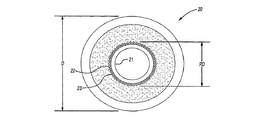
図1ないし図2を参照すると、本発明の構造を具体化している中空繊維膜モジュール20が示されている。モジュール20は芯部21を含み、芯部21上には、第1の端部領域RD1の径を除いて、中空膜繊維22がモジュールの所望の径Dに達するまで螺旋状に巻かれている。RD1の径は、径DからD未満の径へ減少していく。第2の縮小径領域RD2が所望されるならば、図1に示されているように、RD2をモジュール20の他端に設けることができる。当然のことながら、両実施形態のほかに、追加の縮小径領域を有する任意の他の実施形態もまた、十分に本発明の範囲内である。
With reference to FIGS. 1-2, a hollow
そのような構造物を作製するために、中空膜繊維22が芯部21上に敷設される。繊維22のトラバース速度は、繊維が敷設されていく領域によって変わることになる。端部領域ER1またはER2では、トラバース速度は毎秒約6インチ(15.24センチメートル)である。中央領域すなわちアクティブ領域では、速度は毎秒約1インチ(2.54センチメートル)であるので、端部領域における敷設速度は中央領域に比べてずっと大きい。6対1の比である。
In order to produce such a structure, a
敷設の速度は用途によって大きく変わる場合があり、端部領域における敷設の速度は、端部領域の直径を中央領域すなわちアクティブ領域Cの径Dより小さい径まで小さくするのに十分な程大きくなる限りは尚も許容範囲にあることが理解されよう。用途に応じて、縮小径RDは、径Dより幾分小さいだけであり得るか、あるいは実質的に芯部の径であり得る。縮小径RDの区間に隣接している一定部分の中央領域すなわちアクティブ領域Cを有する構成はどれでも、十分に本発明の範囲内である。中央領域Cに隣接する第1の端部から縮小径RDの領域の端部まで一様に小さくなるのが好ましいが、その他の構成も可能である。 The speed of laying may vary greatly depending on the application, as long as the speed of laying in the end region is large enough to reduce the diameter of the end region to a diameter smaller than the diameter D of the central region, ie the active region C. It will be understood that is still acceptable. Depending on the application, the reduced diameter RD can only be somewhat smaller than the diameter D, or can be substantially the diameter of the core. Any configuration having a constant central region or active region C adjacent to a section of reduced diameter RD is well within the scope of the present invention. Although it is preferable that the first end portion adjacent to the central region C is uniformly reduced from the end portion of the region of reduced diameter RD, other configurations are possible.
当然のことながら、巻付角度が中空膜繊維22の全ての層に対して同じである必要はなく、端部領域(R1、R2)におけるトラバース速度が全ての層において異なる必要もない。
Of course, the winding angle need not be the same for all layers of the
図3及び図3Aを参照すると、所望の寸法になるまで芯部に繊維が巻かれた後、管板24がポッティングされる。本発明の実施において、任意の管板ポッティング方法及び当分野で既知の任意のポッティング材料が用いられ得る。ポッティング材料は、用途によって変わり得る。管板24はキュアリング後に切断され、繊維ルーメンが露出する。繊維22はある角度をなして巻かれ、管板24は平らに切断されたので、ルーメン23は、図3Aでは分かりづらいのだが、幾分か楕円の形をしている。
Referring to FIGS. 3 and 3A, after the fibers are wound around the core until the desired dimensions are reached, the
フロー向上のために、管板24は縮小径領域全体を覆わないことが好ましい。管板によって覆われない区間RDAAはアクティブエリアであり、ここを含めて繊維長さが計算されることになる。
In order to improve the flow, the
ここで図4ないし図6を参照すると、そのように作製されたモジュールを用いて、内部スウィープ・ボアサイドフィード型モジュールで芯部にスウィープ収集部が有るもの(27)または無いもの(28)、あるいは外部スウィープ・ボアサイドフィード型モジュール29のいずれかを作製することができる。いずれの場合でも、後述する目的のために、不浸透性ラップ31において作製される繊維束を巻き付ける必要がある。内部スウィープ・ボアサイドフィード型モジュール(27、28)にとって、モジュールのスウィープ入口と反対側にある一端を除く管板24間のモジュール全体がこのラップで覆われることは重要である。あるいは、管板強度を増強するために、不浸透性ラップは、管板に隣接するアクティブエリアを除く繊維束全体を覆い得る。この場合、不浸透性ラップとシェルの間に封止部(32)が設置されることになるであろう。
4 to 6, an internal sweep / bore side feed type module having a sweep collecting part at the core part (27) or not (28), using the module thus manufactured, Alternatively, any of the external sweep / bore side
不浸透性ラップが管板24に埋め込まれないが代わりにシェルにシールされることが本発明に重要であり、このことは、当分野で既知の任意の方法によって、例えば、管板とシェルの間にラップを埋め込むことによって、あるいは管板とシェルの間にガスケットまたは他の封止部を設けることによってなされ得る。
It is important to the present invention that the impervious wrap is not embedded in the
内部スウィープモジュール28では、任意選択でラップとシェルの間に封止部32が設置され得る。スウィープオリフィス33からスウィープガスを中に入れるために、芯部21には管板24に近接して複数のスウィープ孔40が設けられる。
In the
不浸透性ラップ31及び任意選択で封止部32のせいで、スウィープオリフィス31から中に入るスウィープガスは、不浸透性ラップの遠位端31Aに到達するまでは螺旋状に巻かれた繊維24を通って移動することになり、到達後はスウィープ孔から用途に応じて大気中または他の圧力中に放出されることになる。モジュールはシェル内にシールされているので、スウィープガスはスウィープ孔40から外に出ざるを得ない。
Due to the
第1の管板24Aに埋め込まれたルーメン23内に流入する湿性供給ガスは、螺旋状に巻かれた繊維のルーメンを通って移動し、モジュールの向流配置のためにスウィープ入口と反対側の端部でモジュールから出ることになる。当然のことながら、並流構造も用いられることができ、その場合には、乾性ガスがモジュールのスウィープガス入口と同じ側の端部から中に入ることになる。
The wet feed gas flowing into the
ここで図6を参照すると、本発明を用いて作製される外部スウィープ・ボアサイドフィード型中空繊維膜モジュールが示されている。本発明のこの実施形態では、モジュール20は、図3に示したモジュールと同様に繊維が巻かれ得るが、不浸透性ラップ(ここでは明確にするために符号39で示されている)は、モジュールの各端部で所定の距離にわたり開口している。
Referring now to FIG. 6, there is shown an external sweep / bore side feed type hollow fiber membrane module made using the present invention. In this embodiment of the invention, the
不浸透性ラップはスウィープ孔40の領域に終端を有することが好ましいが、これは必須というわけではない。必要に応じて、外部スウィープモジュール29を通過するスウィープガスのフローを制限するためにスウィープ入口周囲にオリフィスを設置することができる。湿性ガスは第1のプレナム46に入り、繊維22のルーメン23を通って第2のプレナム44から出ることになり、乾性ガスは第2のプレナム44から出ることになる。
The impermeable wrap preferably has a termination in the region of the
図7を参照すると、典型的には、モジュール(20、29)は、符号50によって示されるモジュールハウジング内に取り付けられる。シェル25がハウジング50の管状部分51として働き得るか、あるいはシェル25を含むモジュール20をハウジング50の管状部分51の内側にスッポリ入れることができる。いずれの構造でも、1対のエンドキャップ53がハウジングの管状部分51に気密に接続されてハウジングアセンブリ55を形成することになる。脱水される湿性ガスがモジュールアセンブリ55に入る入口57と、脱水されたガスが出ることになる出口59が設けられる。各エンドキャップ53の内側にはプレナム44(図示せず)が設けられる。管状部分51及びエンドキャップ53の構造は、どの型のモジュール27〜29が用いられているかによって変わる。
With reference to FIG. 7, typically the modules (20, 29) are mounted within a module housing indicated by
ハウジングアセンブリ55の分解図が図8に示されている。ハウジングアセンブリ55は、スウィープ開口部及びスウィープ出口を有するモジュールハウジング50を含む。エンドキャップ53をモジュールハウジング50の端部上へねじ込んで、管板24を有する中空膜モジュール20をハウジング内にシールする。エンドキャップ53は、必ずしも管状部分上にねじ込まれる必要はないが、接着剤、超音波溶接、または当分野で既知の他の手段によって付着される場合がある。
An exploded view of the
不浸透性ラップ31(図8には図示せず)は、ガスケット32によってハウジングにシールされる。脱水される湿性ガスが入口57から入れるようにエンドキャップ53の内部にプレナム44が設けられる。湿性ガスは、入口プレナム44Aに入り、繊維22のルーメン23を通って、中空繊維膜モジュール20の他端から出口プレナム44B内へ、そしてそこを通って出口59から出る。
An impermeable wrap 31 (not shown in FIG. 8) is sealed to the housing by a
ここで図9を参照すると、入口及び出口圧縮ガスポートが一直線上に配置されるようにハウジング内に設置されているような、例えばエアゾールのコアレッシング(凝集)に用いられる典型的なインラインフィルターハウジング内に設置されているような、螺旋状に巻かれた繊維束の例が示されている。図を簡略化するために管板24は図示されておらず、巻付角度90°の真っ直ぐな繊維が示されている。中空繊維22及び管板24(図示せず)を有する中空膜モジュール20が、シェル25の内部に設置されている。不浸透性ラップ31は、封止部32によってシェル25にシールされている。必要に応じて、不浸透性ラップ31をシェル25にさらにシールするために開口部(図示せず)から自己膨張フォーム36が導入され得る。
Referring now to FIG. 9, a typical in-line filter housing used, for example, for aerosol coalescence, where the inlet and outlet compressed gas ports are installed in the housing so that they are aligned. An example of a spirally wound fiber bundle is shown as installed inside. To simplify the drawing, the
中空繊維膜モジュール20は、符号62及び63によって示される1対の改良エンドキャップを有し、そのことが、ハウジング入口64及びハウジング出口65を有するフィルターハウジング60内に中空繊維膜モジュール20が装着されることを可能にしている。脱水される湿性ガスは、ハウジング入口64に入り、第1のエンドキャップ62の開口部62Aを通って、繊維22のルーメン23を通って、エンドキャップ63に隣接するルーメン23から出る。エンドキャップ63は、大部分のガスの方向を変えて芯部21を通って元来た方向に戻し、第1のエンドキャップ62から放出してハウジング出口65内へ入れるために、特別に作られたものである。しかし、乾性ガスの一部は、特別なスウィープ入口68を通過でき、これは、繊維22の近くを通り、不浸透性ラップ20の下を通って、特別なスウィープ出口孔69から放出され、ハウジングスウィープ出口70から放出される。
The hollow
当分野における問題を注意深く考慮することによって、改良された中空繊維膜モジュールが提供されている。 By carefully considering the problems in the art, improved hollow fiber membrane modules have been provided.
Claims (18)
(a)芯部と、
(b)前記芯部上に巻かれた複数の螺旋状に巻かれた半透性の中空繊維層とを含み、
任意の1つの中空繊維層に対する繊維巻付角度が、一方または両方の端部または管板領域を除いて前記モジュールの軸方向長さに沿って一定であり、
前記複数の層のうち少なくとも一部の層において、前記巻付角度を、前記一定の巻付角度に比べて増加させることにより、前記一方または両方の端部または管板領域において、径及び充填密度が漸減する区間が形成され、
前記一方または両方の端部領域の始まり部分における前記モジュールの径は、中央アクティブ領域における前記中空繊維膜モジュールの径と同じであり、前記一方または両方の端部または管板領域の終端における前記モジュールの径は、前記中央アクティブ領域の径より小さく、
前記一方または両方の端部領域の前記終端における前記モジュールの前記径が、前記芯部の径より大きく、
前記モジュールの前記軸方向長さに沿って異なる繊維層における前記繊維の長さが20パーセントまたはそれ以上の差で変化することを特徴とする中空繊維膜モジュール。 A hollow fiber membrane module in which hollow fibers are spirally wound,
(A) a core part;
(B) a plurality of spirally wound semipermeable hollow fiber layers wound on the core,
Angled fiber winding for any one hollow fiber layer, is a constant along the axial length of the module with the exception of the end or tubesheet region of one or both,
In at least some of the layers of the plurality of layers, the angled said winding, by increasing in comparison with the winding angle of the front Symbol a certain, said at one or both ends or tubesheet region of diameter and A section where the packing density gradually decreases is formed,
The diameter of the module at the beginning of the one or both end regions is the same as the diameter of the hollow fiber membrane module in the central active region, and the module at the end of the one or both ends or tube sheet region Is smaller than the diameter of the central active region,
The diameter of the module at the end of the one or both end regions is greater than the diameter of the core,
A hollow fiber membrane module, wherein the length of the fibers in different fiber layers varies by 20 percent or more along the axial length of the module.
(a)前記中空芯部が、円筒形であり、スウィープガスの導入のために前記モジュールの一端で開口されており、前記芯部と前記シェルの内側と前記エンドキャップの間に画定される区間において前記繊維群の外側にスウィープガスをめぐらせることができるように前記アクティブ領域に隣接して前記中空芯部に複数のスウィープ孔が設けられているような、請求項10の中空繊維膜モジュールと、
(b)前記スウィープガスを逃がすことができるように前記シェルに設けられた少なくとも1つの開口部とを含むことを特徴とする中空繊維膜モジュール。An internal sweep / bore side feed type hollow fiber membrane module,
(A) The hollow core portion has a cylindrical shape and is opened at one end of the module for introducing a sweep gas, and is defined between the core portion, the inside of the shell, and the end cap. The hollow fiber membrane module according to claim 10 , wherein a plurality of sweep holes are provided in the hollow core portion adjacent to the active region so that sweep gas can be swept outside the fiber group.
(B) A hollow fiber membrane module comprising: at least one opening provided in the shell so that the sweep gas can escape.
(a)前記密接に適合するバリア材が両管板領域に隣接する覆われていない領域を除いて前記モジュールの全体にわたって延在するような、請求項10の中空繊維膜モジュールを含み、
(b)封止部が、前記ガス不浸透性材料と前記シェルの内部の間に設けられ、
(c)少なくとも1つのスウィープ入口開口部が、前記シェルの一端に隣接して設けられ、
(d)少なくとも1つのスウィープ出口開口部が、前記シェルの他端に隣接して設けられることを特徴とするモジュール。External sweep / bore side feed type module,
11. The hollow fiber membrane module of claim 10 , wherein (a) the closely fitting barrier material extends throughout the module except for an uncovered region adjacent to both tubesheet regions,
(B) a sealing portion is provided between the gas-impermeable material and the inside of the shell;
(C) at least one sweep inlet opening is provided adjacent one end of the shell;
(D) A module wherein at least one sweep outlet opening is provided adjacent to the other end of the shell.
Applications Claiming Priority (3)
| Application Number | Priority Date | Filing Date | Title |
|---|---|---|---|
| US84648206P | 2006-09-22 | 2006-09-22 | |
| US60/846,482 | 2006-09-22 | ||
| PCT/US2007/020499 WO2008039376A2 (en) | 2006-09-22 | 2007-09-21 | Improved membrane module |
Related Child Applications (1)
| Application Number | Title | Priority Date | Filing Date |
|---|---|---|---|
| JP2012154571A Division JP5568740B2 (en) | 2006-09-22 | 2012-07-10 | Improved membrane module |
Publications (3)
| Publication Number | Publication Date |
|---|---|
| JP2010514544A JP2010514544A (en) | 2010-05-06 |
| JP2010514544A5 JP2010514544A5 (en) | 2010-11-11 |
| JP5199262B2 true JP5199262B2 (en) | 2013-05-15 |
Family
ID=39230766
Family Applications (2)
| Application Number | Title | Priority Date | Filing Date |
|---|---|---|---|
| JP2009529257A Expired - Fee Related JP5199262B2 (en) | 2006-09-22 | 2007-09-21 | Improved membrane module |
| JP2012154571A Expired - Fee Related JP5568740B2 (en) | 2006-09-22 | 2012-07-10 | Improved membrane module |
Family Applications After (1)
| Application Number | Title | Priority Date | Filing Date |
|---|---|---|---|
| JP2012154571A Expired - Fee Related JP5568740B2 (en) | 2006-09-22 | 2012-07-10 | Improved membrane module |
Country Status (8)
| Country | Link |
|---|---|
| US (1) | US7998254B2 (en) |
| EP (1) | EP2083933B1 (en) |
| JP (2) | JP5199262B2 (en) |
| CN (1) | CN101516475B (en) |
| AU (1) | AU2007300579B2 (en) |
| CA (1) | CA2663724A1 (en) |
| HK (1) | HK1135348A1 (en) |
| WO (1) | WO2008039376A2 (en) |
Families Citing this family (11)
| Publication number | Priority date | Publication date | Assignee | Title |
|---|---|---|---|---|
| ES2525033T3 (en) * | 2003-09-29 | 2014-12-16 | Asahi Kasei Chemicals Corporation | Hollow fiber membrane module of external pressure type with fiber density distribution |
| US20090188856A1 (en) * | 2007-10-20 | 2009-07-30 | Robb Benson | Externally Centering Filter Element or Cartridge and Housing and System Utilizing the Same |
| CL2008002533A1 (en) * | 2007-10-20 | 2009-10-09 | Porous Media Corp | A filter assembly comprising a hollow casing open at least at one end at least one closure member that closes the at least one end, the removable closure member being, at least one tubular plate, one or plus holes or openings, an inlet bimpellent chamber formed in the hollow housing |
| CN102238997A (en) * | 2008-11-13 | 2011-11-09 | 白狐技术有限公司 | Method for sealing membrane modules |
| US7875176B2 (en) * | 2009-03-06 | 2011-01-25 | Porous Media Corporation | Membrane module for fluid filtration |
| EP2555852B1 (en) * | 2010-04-05 | 2015-09-16 | Generon IGS, Inc. | Integrated membrane module for gas dehydration and gas separation |
| JP6738835B2 (en) | 2015-06-09 | 2020-08-12 | エボニック ファイバース ゲゼルシャフト ミット ベシュレンクテル ハフツングEvonik Fibres GmbH | Novel cartridges and modules for fluid separation |
| WO2021034934A1 (en) * | 2019-08-19 | 2021-02-25 | Roth Jason Todd | Data center cooling system and related methods |
| CZ2019550A3 (en) * | 2019-08-23 | 2020-11-18 | Vysoké Učení Technické V Brně | Heat exchanger for liquid - gas application and producing it |
| KR20240041365A (en) | 2021-08-03 | 2024-03-29 | 에보닉 오퍼레이션스 게엠베하 | Apparatus and method for simultaneous processing of different fluctuating gas flows |
| WO2024156842A1 (en) | 2023-01-27 | 2024-08-02 | Evonik Operations Gmbh | Apparatus and method for simultaneously treating different fluctuating gas flows in the field of methanation |
Family Cites Families (38)
| Publication number | Priority date | Publication date | Assignee | Title |
|---|---|---|---|---|
| JPS4955569A (en) * | 1972-10-03 | 1974-05-29 | ||
| US4949252A (en) * | 1985-10-17 | 1990-08-14 | Technology 80, Inc. | Computer channel analyzer with monitoring and selective display of predetermining events and related data |
| US4773003A (en) * | 1985-10-17 | 1988-09-20 | Technology 80, Inc. | Apparatus for monitoring and analyzing large data blocks on a computer channel |
| EG18145A (en) * | 1985-12-10 | 1992-08-30 | Albany Int Corp | Hollow fiber separatory modul with encased fiber bundle |
| US4865736A (en) * | 1985-12-10 | 1989-09-12 | Albany International Corp. | Hollow fiber separatory module with encased fiber bundle |
| US4881955A (en) * | 1988-09-12 | 1989-11-21 | Union Carbide Corporation | Method for gas separation using helically wound hollow fibers permeable membrane cartridge |
| US4880440A (en) * | 1988-09-12 | 1989-11-14 | Union Carbide Corporation | Hollow fiber multimembrane cells and permeators |
| US5026479A (en) * | 1990-02-13 | 1991-06-25 | Union Carbide Industrial Gases Technology Corporation | Fluid separation device |
| JPH0575628A (en) * | 1991-09-13 | 1993-03-26 | Fuji Xerox Co Ltd | Network resource monitor system |
| US5160042A (en) * | 1991-11-05 | 1992-11-03 | Praxair Technology, Inc. | Double ended hollow fiber bundle and fluids separation apparatus |
| US5376334A (en) * | 1993-05-19 | 1994-12-27 | Avecor Cardiovascular Inc. | Mass transfer device having a hollow fiber bundle |
| US5577254A (en) * | 1993-06-29 | 1996-11-19 | Bull Hn Information Systems Inc. | Method and apparatus for capturing the presentation of an interactive user session, monitoring, replaying and joining sessions |
| US5411662A (en) * | 1994-02-25 | 1995-05-02 | Praxair Technology, Inc. | Fluid separation assembly having an purge control valve |
| US5837033A (en) * | 1996-03-29 | 1998-11-17 | Praxair Technology, Inc. | Hollow fiber membrane separation apparatus |
| US5702601A (en) * | 1996-03-29 | 1997-12-30 | Praxiar Technology, Inc. | Structure enhancing hollow fiber module |
| CA2190043C (en) * | 1996-11-12 | 2001-10-16 | Don E. Hameluck | Buffered screen capturing software tool usability testing of computer applications |
| US6266681B1 (en) * | 1997-04-08 | 2001-07-24 | Network Commerce Inc. | Method and system for inserting code to conditionally incorporate a user interface component in an HTML document |
| US6199104B1 (en) * | 1997-04-28 | 2001-03-06 | Sabre Inc. | Server-based host monitor |
| DE19732033A1 (en) * | 1997-07-25 | 1999-01-28 | Bayer Ag | Triazolinethione-phosphoric acid derivatives |
| US6101482A (en) * | 1997-09-15 | 2000-08-08 | International Business Machines Corporation | Universal web shopping cart and method of on-line transaction processing |
| US6195679B1 (en) * | 1998-01-06 | 2001-02-27 | Netscape Communications Corporation | Browsing session recording playback and editing system for generating user defined paths and allowing users to mark the priority of items in the paths |
| US6236987B1 (en) * | 1998-04-03 | 2001-05-22 | Damon Horowitz | Dynamic content organization in information retrieval systems |
| US6414725B1 (en) * | 1998-04-16 | 2002-07-02 | Leitch Technology Corporation | Method and apparatus for synchronized multiple format data storage |
| US6526442B1 (en) * | 1998-07-07 | 2003-02-25 | Compaq Information Technologies Group, L.P. | Programmable operational system for managing devices participating in a network |
| US6286030B1 (en) * | 1998-07-10 | 2001-09-04 | Sap Aktiengesellschaft | Systems and methods for recording and visually recreating sessions in a client-server environment |
| US6223213B1 (en) * | 1998-07-31 | 2001-04-24 | Webtv Networks, Inc. | Browser-based email system with user interface for audio/video capture |
| US6697824B1 (en) * | 1999-08-31 | 2004-02-24 | Accenture Llp | Relationship management in an E-commerce application framework |
| US6745367B1 (en) * | 1999-09-27 | 2004-06-01 | International Business Machines Corporation | Method and computer program product for implementing parental supervision for internet browsing |
| US6616735B1 (en) * | 1999-11-12 | 2003-09-09 | Porous Media Corporation | Compressed gas systems utilizing a variable pressure membrane air drier, and method of operation thereof |
| US6662226B1 (en) * | 2000-01-27 | 2003-12-09 | Inbit, Inc. | Method and system for activating and capturing screen displays associated with predetermined user interface events |
| US6883032B1 (en) * | 2000-02-02 | 2005-04-19 | Lucent Technologies Inc. | Method and system for collecting data on the internet |
| US6978304B2 (en) * | 2000-05-26 | 2005-12-20 | Pearl Software, Inc. | Method of remotely monitoring an internet session |
| US20030061506A1 (en) * | 2001-04-05 | 2003-03-27 | Geoffrey Cooper | System and method for security policy |
| WO2002045822A1 (en) * | 2000-12-08 | 2002-06-13 | Porous Media Corporation | Membrane air dryer with integral diffuser and method or manufacture thereof |
| US6779522B2 (en) * | 2001-10-16 | 2004-08-24 | Perma Pure, Inc. | Method and apparatus for treating breathing gases |
| US7149788B1 (en) * | 2002-01-28 | 2006-12-12 | Witness Systems, Inc. | Method and system for providing access to captured multimedia data from a multimedia player |
| US7219138B2 (en) * | 2002-01-31 | 2007-05-15 | Witness Systems, Inc. | Method, apparatus, and system for capturing data exchanged between a server and a user |
| DE10259661A1 (en) * | 2002-10-16 | 2004-04-29 | Beko Technologies Gmbh | Hollow fiber module |
-
2007
- 2007-09-21 CN CN200780035115.2A patent/CN101516475B/en active Active
- 2007-09-21 WO PCT/US2007/020499 patent/WO2008039376A2/en active Application Filing
- 2007-09-21 JP JP2009529257A patent/JP5199262B2/en not_active Expired - Fee Related
- 2007-09-21 CA CA002663724A patent/CA2663724A1/en not_active Abandoned
- 2007-09-21 AU AU2007300579A patent/AU2007300579B2/en not_active Ceased
- 2007-09-21 EP EP07838656.2A patent/EP2083933B1/en active Active
- 2007-09-21 US US11/903,337 patent/US7998254B2/en active Active
-
2010
- 2010-02-22 HK HK10101852.3A patent/HK1135348A1/en not_active IP Right Cessation
-
2012
- 2012-07-10 JP JP2012154571A patent/JP5568740B2/en not_active Expired - Fee Related
Also Published As
| Publication number | Publication date |
|---|---|
| AU2007300579B2 (en) | 2011-12-22 |
| WO2008039376A3 (en) | 2008-06-26 |
| JP2012223765A (en) | 2012-11-15 |
| AU2007300579A1 (en) | 2008-04-03 |
| US20080072754A1 (en) | 2008-03-27 |
| HK1135348A1 (en) | 2010-06-04 |
| CN101516475B (en) | 2013-05-08 |
| US7998254B2 (en) | 2011-08-16 |
| WO2008039376A8 (en) | 2008-08-14 |
| EP2083933A4 (en) | 2012-09-19 |
| EP2083933B1 (en) | 2014-02-26 |
| EP2083933A2 (en) | 2009-08-05 |
| JP5568740B2 (en) | 2014-08-13 |
| JP2010514544A (en) | 2010-05-06 |
| CA2663724A1 (en) | 2008-04-03 |
| WO2008039376A2 (en) | 2008-04-03 |
| CN101516475A (en) | 2009-08-26 |
Similar Documents
| Publication | Publication Date | Title |
|---|---|---|
| JP5568740B2 (en) | Improved membrane module | |
| US10926225B2 (en) | Hollow fiber cartridges and components and methods of their construction | |
| EP0669158B1 (en) | Fluid separation assembly having an integral purge control valve | |
| US3422008A (en) | Wound hollow fiber permeability apparatus and process of making the same | |
| US4367139A (en) | Hollow fiber permeator | |
| JP5536080B2 (en) | Central core element for spirally wound separator assembly | |
| US4715953A (en) | Hollow fiber separation device manifold | |
| US7803274B2 (en) | Contained liquid membrane contactor and a method of manufacturing the same | |
| JPH05504298A (en) | Spiral-wound membrane separator with feed and permeate/sweep fluid flow control | |
| JP2010514544A5 (en) | ||
| CN1072108A (en) | Double ended hollow fiber bundle and fluid separation device | |
| JP2000516852A (en) | Hollow, multi-dimensional array of thin films | |
| JP2012223765A5 (en) | ||
| US4105548A (en) | Separation device of rigid porous inorganic hollow filament and use thereof | |
| KR20110052596A (en) | Filtration system having fluid couplings | |
| PT1689516E (en) | The separation of solid particles from the liquid in which they are dispersed | |
| JPH08942A (en) | Dehumidifying hollow fiber membrane model | |
| JP5356882B2 (en) | Pleated molded body manufacturing method and pleated molded body | |
| JPS6013722B2 (en) | membrane separation equipment | |
| JP2009095829A (en) | Water separating hollow fiber and water separating filter | |
| JPH05161832A (en) | Hollow yarn membrane module and separation method using the same | |
| JP2010234201A (en) | Method of manufacturing pleat formed body and pleat formed body | |
| KR20020013036A (en) | Gas separation membraines for dehumidifying module | |
| MXPA00001226A (en) | Method for producing cellulosic shaped bodies |
Legal Events
| Date | Code | Title | Description |
|---|---|---|---|
| A521 | Request for written amendment filed |
Free format text: JAPANESE INTERMEDIATE CODE: A523 Effective date: 20100920 |
|
| A621 | Written request for application examination |
Free format text: JAPANESE INTERMEDIATE CODE: A621 Effective date: 20100920 |
|
| A977 | Report on retrieval |
Free format text: JAPANESE INTERMEDIATE CODE: A971007 Effective date: 20111012 |
|
| A131 | Notification of reasons for refusal |
Free format text: JAPANESE INTERMEDIATE CODE: A131 Effective date: 20120110 |
|
| A601 | Written request for extension of time |
Free format text: JAPANESE INTERMEDIATE CODE: A601 Effective date: 20120405 |
|
| A602 | Written permission of extension of time |
Free format text: JAPANESE INTERMEDIATE CODE: A602 Effective date: 20120412 |
|
| A601 | Written request for extension of time |
Free format text: JAPANESE INTERMEDIATE CODE: A601 Effective date: 20120510 |
|
| A602 | Written permission of extension of time |
Free format text: JAPANESE INTERMEDIATE CODE: A602 Effective date: 20120517 |
|
| A601 | Written request for extension of time |
Free format text: JAPANESE INTERMEDIATE CODE: A601 Effective date: 20120611 |
|
| A602 | Written permission of extension of time |
Free format text: JAPANESE INTERMEDIATE CODE: A602 Effective date: 20120618 |
|
| A521 | Request for written amendment filed |
Free format text: JAPANESE INTERMEDIATE CODE: A523 Effective date: 20120710 |
|
| TRDD | Decision of grant or rejection written | ||
| A01 | Written decision to grant a patent or to grant a registration (utility model) |
Free format text: JAPANESE INTERMEDIATE CODE: A01 Effective date: 20130115 |
|
| A61 | First payment of annual fees (during grant procedure) |
Free format text: JAPANESE INTERMEDIATE CODE: A61 Effective date: 20130207 |
|
| FPAY | Renewal fee payment (event date is renewal date of database) |
Free format text: PAYMENT UNTIL: 20160215 Year of fee payment: 3 |
|
| R150 | Certificate of patent or registration of utility model |
Ref document number: 5199262 Country of ref document: JP Free format text: JAPANESE INTERMEDIATE CODE: R150 Free format text: JAPANESE INTERMEDIATE CODE: R150 |
|
| R250 | Receipt of annual fees |
Free format text: JAPANESE INTERMEDIATE CODE: R250 |
|
| R250 | Receipt of annual fees |
Free format text: JAPANESE INTERMEDIATE CODE: R250 |
|
| R250 | Receipt of annual fees |
Free format text: JAPANESE INTERMEDIATE CODE: R250 |
|
| R250 | Receipt of annual fees |
Free format text: JAPANESE INTERMEDIATE CODE: R250 |
|
| R250 | Receipt of annual fees |
Free format text: JAPANESE INTERMEDIATE CODE: R250 |
|
| R250 | Receipt of annual fees |
Free format text: JAPANESE INTERMEDIATE CODE: R250 |
|
| LAPS | Cancellation because of no payment of annual fees |