JP5198583B2 - Mini resource design and transmission method for distributed resource units considering spatial frequency - Google Patents
Mini resource design and transmission method for distributed resource units considering spatial frequency Download PDFInfo
- Publication number
- JP5198583B2 JP5198583B2 JP2010547575A JP2010547575A JP5198583B2 JP 5198583 B2 JP5198583 B2 JP 5198583B2 JP 2010547575 A JP2010547575 A JP 2010547575A JP 2010547575 A JP2010547575 A JP 2010547575A JP 5198583 B2 JP5198583 B2 JP 5198583B2
- Authority
- JP
- Japan
- Prior art keywords
- dru
- pru
- subcarriers
- pair
- mru
- Prior art date
- Legal status (The legal status is an assumption and is not a legal conclusion. Google has not performed a legal analysis and makes no representation as to the accuracy of the status listed.)
- Expired - Fee Related
Links
Images


Classifications
-
- H—ELECTRICITY
- H04—ELECTRIC COMMUNICATION TECHNIQUE
- H04L—TRANSMISSION OF DIGITAL INFORMATION, e.g. TELEGRAPHIC COMMUNICATION
- H04L5/00—Arrangements affording multiple use of the transmission path
- H04L5/0001—Arrangements for dividing the transmission path
- H04L5/0014—Three-dimensional division
- H04L5/0023—Time-frequency-space
-
- H—ELECTRICITY
- H04—ELECTRIC COMMUNICATION TECHNIQUE
- H04L—TRANSMISSION OF DIGITAL INFORMATION, e.g. TELEGRAPHIC COMMUNICATION
- H04L1/00—Arrangements for detecting or preventing errors in the information received
- H04L1/02—Arrangements for detecting or preventing errors in the information received by diversity reception
- H04L1/06—Arrangements for detecting or preventing errors in the information received by diversity reception using space diversity
- H04L1/0606—Space-frequency coding
-
- H—ELECTRICITY
- H04—ELECTRIC COMMUNICATION TECHNIQUE
- H04L—TRANSMISSION OF DIGITAL INFORMATION, e.g. TELEGRAPHIC COMMUNICATION
- H04L1/00—Arrangements for detecting or preventing errors in the information received
- H04L1/02—Arrangements for detecting or preventing errors in the information received by diversity reception
- H04L1/06—Arrangements for detecting or preventing errors in the information received by diversity reception using space diversity
- H04L1/0618—Space-time coding
-
- H—ELECTRICITY
- H04—ELECTRIC COMMUNICATION TECHNIQUE
- H04L—TRANSMISSION OF DIGITAL INFORMATION, e.g. TELEGRAPHIC COMMUNICATION
- H04L5/00—Arrangements affording multiple use of the transmission path
- H04L5/0001—Arrangements for dividing the transmission path
- H04L5/0003—Two-dimensional division
- H04L5/0005—Time-frequency
- H04L5/0007—Time-frequency the frequencies being orthogonal, e.g. OFDM(A), DMT
-
- H—ELECTRICITY
- H04—ELECTRIC COMMUNICATION TECHNIQUE
- H04L—TRANSMISSION OF DIGITAL INFORMATION, e.g. TELEGRAPHIC COMMUNICATION
- H04L5/00—Arrangements affording multiple use of the transmission path
- H04L5/003—Arrangements for allocating sub-channels of the transmission path
- H04L5/0042—Arrangements for allocating sub-channels of the transmission path intra-user or intra-terminal allocation
-
- H—ELECTRICITY
- H04—ELECTRIC COMMUNICATION TECHNIQUE
- H04L—TRANSMISSION OF DIGITAL INFORMATION, e.g. TELEGRAPHIC COMMUNICATION
- H04L5/00—Arrangements affording multiple use of the transmission path
- H04L5/003—Arrangements for allocating sub-channels of the transmission path
- H04L5/0044—Arrangements for allocating sub-channels of the transmission path allocation of payload
-
- H—ELECTRICITY
- H04—ELECTRIC COMMUNICATION TECHNIQUE
- H04L—TRANSMISSION OF DIGITAL INFORMATION, e.g. TELEGRAPHIC COMMUNICATION
- H04L5/00—Arrangements affording multiple use of the transmission path
- H04L5/003—Arrangements for allocating sub-channels of the transmission path
- H04L5/0048—Allocation of pilot signals, i.e. of signals known to the receiver
-
- H—ELECTRICITY
- H04—ELECTRIC COMMUNICATION TECHNIQUE
- H04L—TRANSMISSION OF DIGITAL INFORMATION, e.g. TELEGRAPHIC COMMUNICATION
- H04L5/00—Arrangements affording multiple use of the transmission path
- H04L5/003—Arrangements for allocating sub-channels of the transmission path
- H04L5/0053—Allocation of signaling, i.e. of overhead other than pilot signals
Landscapes
- Engineering & Computer Science (AREA)
- Signal Processing (AREA)
- Computer Networks & Wireless Communication (AREA)
- Mobile Radio Communication Systems (AREA)
- Radio Transmission System (AREA)
Description
本発明は、空間周波数ブロックコーディング(Space Frequency Block Coding、SFBC)をサポートする広帯域無線移動通信システムに関するものである。 The present invention relates to a broadband wireless mobile communication system that supports space frequency block coding (SFBC).
フェーディング(Fading)は、搬送波が変調された遠距離通信信号が特定の伝播メディアを経験しながら発生する歪曲である。フェーディングチャンネルは、フェーディングが発生する通信チャンネルをいう。無線システムにおいて、フェーディングは、多重経路伝播によって発生し、多重経路誘発フェーディングといわれることもある。 Fading is a distortion that occurs when a telecommunications signal with a modulated carrier wave experiences a specific propagation medium. A fading channel refers to a communication channel in which fading occurs. In wireless systems, fading is caused by multipath propagation and is sometimes referred to as multipath induced fading.
無線通信では、送信機と受信機を取り囲む環境での反射材により、送信信号が通過する複数の経路が生成される。その結果、受信機は、互いに異なる経路を通過した送信信号の多数の複写本における重畳(superposition)された信号を受信するようになる。各信号の複写本は、送信機から受信機まで伝播される間、互いに異なる減衰、遅延及び位相遷移を経験するようになる。その結果、受信機側では、補強干渉(constructive interference)又は相殺干渉(destructive interference)、信号電力の減衰又は増幅を経験する。強い相殺干渉は、ディープフェーディング(deep fade)ともいわれ、これによってチャンネルの信号対雑音比が深刻に損傷され、結果として、一時的な通信の失敗につながるようになる。 In wireless communication, a plurality of paths through which a transmission signal passes are generated by a reflecting material in an environment surrounding a transmitter and a receiver. As a result, the receiver receives signals superimposed on a large number of copies of transmission signals that have passed through different paths. Each signal copy book will experience different attenuation, delay and phase transitions while propagating from the transmitter to the receiver. As a result, the receiver side experiences reinforced interference or destructive interference and signal power attenuation or amplification. Strong destructive interference is also referred to as deep fading, which severely damages the channel's signal-to-noise ratio, resulting in temporary communication failure.
無線通信において、ダイバーシティ方式は、互いに異なる特性を有する二つ以上の通信チャンネルを使用することによってメッセージの信頼性を向上させる方法をいう。ダイバーシティは、フェーディング及び共同チャンネル干渉に対抗し、バーストエラーを避けるための重要な役割をする。ダイバーシティは、それぞれのチャンネルが互いに異なる水準のフェーディング及び干渉を経験するために存在する。同一の信号に対する複数の複写本が伝送されれば、受信機では、これら複写本を組み合わせることができる。また、余剰の前方エラー補正コードが追加され、メッセージの互いに異なる部分は互いに異なるチャンネルを介して伝送することができる。ダイバーシティ方式は、多重経路伝播現象を用いるもので、この方式によれば、デシベル(decibel)で測定されるダイバーシティ利得を得ることができる。 In wireless communication, the diversity scheme refers to a method of improving message reliability by using two or more communication channels having different characteristics. Diversity plays an important role in combating fading and co-channel interference and avoiding burst errors. Diversity exists because each channel experiences different levels of fading and interference. If a plurality of copy books for the same signal are transmitted, the receiver can combine these copy books. Also, an extra forward error correction code is added and different parts of the message can be transmitted over different channels. The diversity method uses a multipath propagation phenomenon, and according to this method, a diversity gain measured in decibels can be obtained.
ダイバーシティ方式は、時間ダイバーシティ、周波数ダイバーシティ、空間ダイバーシティ、分極ダイバーシティ、多重ユーザダイバーシティ及び協力的ダイバーシティなどに分類される。このうち、時間ダイバーシティでは、同一の信号に対する様々な複写本が互いに異なる時点に到逹される。また、余剰の前方エラー補正コードが追加され、メッセージは、送信される前にビット―インターリービングによって時間上で拡散される。したがって、エラーバーストを予防することができ、エラー補正が簡単に行われる。周波数ダイバーシティによれば、信号は、多数の周波数チャンネルを介して送信されたり、又は、周波数―選択的フェーディングによって影響を受ける広帯域スペクトルにわたって拡散される。 Diversity schemes are classified into time diversity, frequency diversity, spatial diversity, polarization diversity, multiple user diversity, cooperative diversity, and the like. Of these, in time diversity, various copy books for the same signal arrive at different points in time. Also, an extra forward error correction code is added and the message is spread in time by bit-interleaving before being sent. Therefore, error burst can be prevented and error correction is easily performed. According to frequency diversity, a signal is transmitted over multiple frequency channels or spread over a wideband spectrum that is affected by frequency-selective fading.
広帯域無線移動通信システムにおいて、各資源は、送信時に分散される方式で割り当てられるが、これによって、周波数ダイバーシティ利得を得るようになる。資源の分散割り当てのための各方法は、ユーザに割り当てられる分散資源ユニット(Distributed Resource Units、DRU)の個数の組み合わせによって異なり、このユーザのためにDRUを割り当てるための使用可能な帯域幅によって異なる。ユーザに割り当てられるDRUの個数は、このユーザに割り当てられるパケットサイズに比例し、DRUを形成するための利用可能な帯域幅は、このユーザに割り当てられる論理資源ユニット(Logical Resource Units、LRU)の個数に比例する。 In a broadband wireless mobile communication system, each resource is allocated in a distributed manner at the time of transmission, thereby obtaining a frequency diversity gain. Each method for distributed allocation of resources depends on a combination of the number of distributed resource units (DRUs) allocated to a user and depends on the available bandwidth for allocating DRUs for this user. The number of DRUs allocated to a user is proportional to the packet size allocated to this user, and the available bandwidth for forming a DRU is the number of logical resource units (Logical Resource Units, LRUs) allocated to this user. Is proportional to
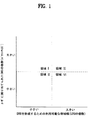
図1は、DRUを形成するためのLRUの個数(利用可能な帯域幅)及びパケットサイズの可能な組み合わせを示す図である。 FIG. 1 is a diagram illustrating possible combinations of the number of LRUs (available bandwidth) and packet sizes for forming a DRU.
図1の領域1は、少量の利用可能な帯域幅及び大きいパケットサイズの組み合わせを示し、領域3は、大量の利用可能な帯域幅及び大きいパケットサイズの組み合わせを示す。領域1及び領域3で、利用可能な各分散資源割り当て方式間の性能差は無視してもよいが、これは、これら各領域でパケットサイズが大きいので、パケットが周波数上で拡散される可能性がより大きいためである。
しかし、領域4でも、断片PRU(fractional physical resource unit)のサイズ又はミニ物理資源ユニット(Mini physical Resource Unit、MRU)のサイズが小さい場合、利用可能な各分散資源割り当て方式間の性能差はそれほど大きくないが、これは、DRUを形成するための大きい利用可能な帯域幅のために、各MRUが周波数軸上で拡張される方式で小さいサイズのMRUの個数が割り当てられるためである。したがって、ダイバーシティ利得の観点で、MRUのサイズが小さいほど、システム性能は良くなる。したがって、DRUを形成するための最小ユニットとして1個のサブキャリアが使用される場合、最小ユニットを形成する他の構造を使用する場合に比べて、より大きいダイバーシティ利得を得ることができる。
However, even in the
しかし、DRUを形成するための最小ユニットとして一つのMRUを設計する方法は、ダイバーシティ側面だけでなく、柔軟性の側面でも接近されなければならないが、これは、無線移動通信システムが様々なサブフレーム構成をサポートできるためである。例えば、通信システムは、部分周波数再使用(Fractional Frequency Reuse、FFR)、及びDRUとCRUに対する周波数分割多重化(Frequency Division Multiplexing、FDM)を採択することができる。ここで、CRUは、連続的な資源ユニットであって、分散資源ユニットともいわれる。また、特定の各構成では、空間時間ブロックコード(Space―Time Block Code、STBC)がデータ伝送に適していないサブフレーム構成が存在しうる。STBCは、奇数個のシンボルを有するサブフレームには適していない。時分割二重化(Time Division Duplexing、TDD)モードでは、送信遷移ギャップ(Transmission Transition Gap、TTG)に対する非正規サブフレーム(5シンボル)に対して、プリアンブルを含むサブフレームに対して、ミッドアンブル(mid―amble)を含むサブフレームに対して、他の循環前置サイズ(Cyclic Prefix size、CP size)(例えば、1/16CPのための7個のシンボル)に対して、そして、時分割多重化(Time Division Multiplexing、TDM)MAPを含むサブフレームなどに対して、総奇数個のシンボルが割り当てられる。周波数分割二重化(Frequency Division Duplexing、FDD)モードでは、プリアンブルを含むサブフレームに対して、ミッドアンブルを含むサブフレームに対して、他のCPサイズ(例えば、1/16CPのための7個のシンボル)に対して、そして、TDM MAPを含むサブフレームなどに対して、総奇数個のシンボルが割り当てられる。 However, the method of designing one MRU as a minimum unit for forming a DRU must be approached not only in terms of diversity but also in terms of flexibility. This is because the configuration can be supported. For example, the communication system can adopt partial frequency reuse (FFR) and frequency division multiplexing (FDM) for DRU and CRU. Here, the CRU is a continuous resource unit and is also called a distributed resource unit. In each specific configuration, there may be a subframe configuration in which the space-time block code (Space-Time Block Code, STBC) is not suitable for data transmission. STBC is not suitable for subframes having an odd number of symbols. In the Time Division Duplexing (TDD) mode, the mid-amble (mid−) for the subframe including the preamble with respect to the non-normal subframe (5 symbols) for the transmission transition gap (Transmission Transition Gap, TTG). for subframes that include (amble), for other cyclic prefix sizes (CP size) (eg, 7 symbols for 1/16 CP), and for time division multiplexing (Time (Division Multiplexing, TDM) A total of an odd number of symbols is allocated to a subframe including a MAP. In Frequency Division Duplexing (FDD) mode, other CP sizes (eg, 7 symbols for 1/16 CP) for subframes that include the preamble and subframes that include the midamble. And, for subframes including TDM MAP, a total odd number of symbols is allocated.
STBCが多くの種類のサブフレーム構成に適していないとしても、空間周波数ブロックコーディング(Spatial Frequency Block Coding、SFBC)は、全てのサブフレーム構成をサポートすることができる。したがって、本発明の発明者らが公開したように、ダイバーシティ利得性能を考慮しながら、STBCをSFBCに取り替えるためのDRUを形成するための最小ユニットに対する構造を作る必要があり、STBC及びSFBCを全てサポートするための構造を作る必要がある。 Spatial Frequency Block Coding (SFBC) can support all subframe configurations, even though STBC is not suitable for many types of subframe configurations. Therefore, as disclosed by the inventors of the present invention, it is necessary to create a structure for a minimum unit for forming a DRU for replacing STBC with SFBC while considering diversity gain performance, and all STBC and SFBC are formed. You need to create a structure to support it.
本発明によって解決すべき技術的な問題は、SFBC MIMOをサポートしながら強いダイバーシティ利得を提供するDRUを形成するための最小ユニットのサイズを決定し、その伝送方法を設計することにある。 The technical problem to be solved by the present invention is to determine the size of the smallest unit to form a DRU that provides strong diversity gain while supporting SFBC MIMO, and to design the transmission method.
本発明の一様相において、移動通信端末と基地局との間での無線通信方法が提供される。この方法は、基地局と移動通信端末との間でPRUを交換することを含むが、このとき、PRUは、複数のOFDMAシンボルを有する。それぞれの1番目のOFDMAシンボルは、予め決定されたパイロット割り当て方式によって割り当てられるnl個のパイロットを含み、前記l番目のOFDMAシンボルのうち残っているLDRU・(Psc−nl)個のデータサブキャリアは、0からLDRU(Psc−nl)−1までリナンバリングされる。このとき、論理的に隣接するリナンバリングされた各サブキャリアは、LDRU・Lpair,l個のペアにグルーピングされ、0からLDRU・Lpair,l−1にリナンバリングされる。0〜LDRU・Lpair,l−1のトーン―ペア(tone pairs)が形成されれば、各ペアに対して予め決定されたパーミュテーション公式が適用され、論理的に連続したトーン―ペア(i・Lpair,l;(i+1)・Lpair,l−1)は、i番目の分散されたLRUにマッピングされる。ここで、i=0、1、…、LDRU−1、LDRU=DRUの個数、Psc=PRU内でのOFDMAシンボルでのサブキャリアの個数で、Lpair,l=(Psc−nl)/2である。 In one aspect of the present invention, a method for wireless communication between a mobile communication terminal and a base station is provided. The method includes exchanging PRUs between a base station and a mobile communication terminal, where the PRU has a plurality of OFDMA symbols. Each first OFDMA symbol includes n l pilots allocated by a predetermined pilot allocation scheme, and the remaining L DRU · (P sc −n l ) L DRU · (P sc −n l ) of the l th OFDMA symbols. Data subcarriers are renumbered from 0 to L DRU (P sc −n 1 ) −1. In this case, each sub-carrier which is renumbered logically contiguous, L DRU · L pair, grouped into l number of pairs, are renumbered from 0 L DRU · L pair, a l -1. If tone-pairs of 0 to L DRU · L pair, l −1 are formed, a predetermined permutation formula is applied to each pair, and a logically continuous tone-pair (I · L pair, l ; (i + 1) · L pair, l −1) is mapped to the i th distributed LRU. Here, i = 0, 1,..., L DRU −1, L DRU = DRU number, P sc = The number of subcarriers in the OFDMA symbol in PRU, and L pair, l = (P sc −n l ) / 2.
発明の一側面で、移動通信端末と基地局との間での無線通信方法が提供される。この方法は、基地局と端末との間でPRUを取り交わすことを含むが、このPRUは、多数のOFDMAシンボルで構成されている。サブフレームに存在するそれぞれのl番目のOFDMAシンボルで、各DRU内のnl個のパイロットは、予め決定された割り当て方法に合わせて割り当てられる。l番目のOFDMAシンボル内にあるDRUFPi[j]に属する各データサブキャリアをSC_DRUFPi[j],l[n]、0≦j<LDRU,FPi、and 0≦n<LSC,l.と定義するが、ここで、DRUFPi[・]は、i番目の周波数パーティション(frequency partition)に存在する各DRUを意味し、LDRU,FPiはi番目の周波数パーティションに存在するDRUFPi[・]の個数を意味し、LSC,lは、一つのPRU内にあるl番目のOFDMAシンボルでのデータサブキャリアの数を意味する。すなわち、LSC,l=Psc−nlで、ここで、Pscは、一つのPRU内の一つのOFDMAシンボルでのサブキャリアの数を意味する。各DRUのLDRU,FPi・LSC,lだけのデータサブキャリアを0からLDRU,FPi・LSC,l−1まで順次リナンバリングする。このように論理的に連続したリナンバリングした各サブキャリアをLDRU,FPi・LSP,lペアにグルーピングし、これらを0からLDRU,FPi・LSP,l−1までリナンバリングする。ここで、LSP,lは、一つのPRU内にあるl番目のOFDMAシンボルでのデータサブキャリアペアの数を意味し、LSC,l/2と同一である。リナンバリングされたl番目のOFDMAシンボルでのサブキャリアペアをRSPFPi,lと称し、これは、{SC_DRUFPi[j],l[2v],SC_DRUFPi[j],l[2v+1]}、0<=u<LDRU,FPi・LSP,l(ここで、j=floor(u/LSP,l)、v=u mod LSP,l)と同一である。予め決定されたパーミュテーション公式によって、RSPFPi,lはs番目の分散LRUにマッピングされるが、ここで、s=0、1、…、LDRU,FPi−1である。ここで、「mod」は、モジュロ演算を意味する。本発明では、前記「サブキャリアペア」又は「トーン―ペア」という用語が使用される。 In one aspect of the invention, a wireless communication method between a mobile communication terminal and a base station is provided. This method includes exchanging PRUs between a base station and a terminal, and this PRU is composed of a number of OFDMA symbols. In each l-th OFDMA symbol present in the subframe, n l pilots in each DRU are allocated according to a predetermined allocation method. Each data subcarrier belonging to DRU FPi [j] in the l-th OFDMA symbol is represented by SC_DRU FPi [j], l [n], 0 ≦ j <L DRU, FPi , and 0 ≦ n <L SC, l. Although defined as, where, DRU FPi [·] means each DRU existing in i-th frequency partition (frequency partition), L DRU, FPi is present in the i-th frequency partition DRU FPi [· means a number of], L SC, l denotes the number of data subcarriers in l th OFDMA symbol within a PRU. That is, L SC, l = Psc-n l , where Psc means the number of subcarriers in one OFDMA symbol in one PRU. The data subcarriers of L DRU, FPi · L SC, l of each DRU are renumbered sequentially from 0 to L DRU, FPi · L SC, l −1. The subcarriers renumbered logically in this way are grouped into L DRU, FPi · L SP, l pairs, and these are renumbered from 0 to L DRU, FPi · L SP, l −1. Here, L SP, l means the number of data subcarrier pairs in the l-th OFDMA symbol in one PRU and is the same as L SC, l / 2. The subcarrier pair in the renumbered l-th OFDMA symbol is referred to as RSP FPi, l , which is {SC_DRU FPi [j], l [2v], SC_DRU FPi [j], l [2v + 1]}, 0 <= U <L DRU, FPi · L SP, l (where j = floor (u / L SP, l ), v = u mod L SP, l ). According to a pre-determined permutation formula, RSP FPi, l is mapped to the sth distributed LRU, where s = 0, 1,..., L DRU, FPi −1. Here, “mod” means a modulo operation. In the present invention, the terms “subcarrier pair” or “tone-pair” are used.
本発明の他の様相において、前記交換するのは、PRUを基地局から移動通信端末に送信することを含む。 In another aspect of the invention, the exchanging includes transmitting the PRU from the base station to the mobile communication terminal.
本発明の他の様相において、前記交換するのは、移動通信端末がPRUを基地局から受信することを含む。 In another aspect of the invention, the exchanging includes a mobile communication terminal receiving a PRU from a base station.
本発明の他の様相において、前記予め決定されたパーミュテーション公式は、t番目のサブフレームのs番目分散論理資源ユニットに対して「ペア(s,m,l,t)」=LDRU・f(m,s)+g(PermSeq(),s,m,l,t)によって与えられる。ここで、l=0、1、…、Nsym−1で、「ペア(s,m,l,t)」は、t番目のサブフレームのs番目の分散論理資源ユニット内のl番目(0<=l<Nsym)のOFDMAシンボル内のm番目(0<=m<Lpair,l)のトーン―ペアのトーン―ペアインデックスで、tは、フレームに対するサブフレームインデックスで、sは、分散論理資源ユニットのインデックス(0<=s<LDRU)で、mは、前記l番目のOFDMAシンボル内のトーン―ペアインデックスで、PermSeq()は、予め決定された関数又は検索テーブルによって生成されるパーミュテーションシーケンスである。 In another aspect of the present invention, the predetermined permutation formula is “pair (s, m, l, t)” = L DRU · for the s th distributed logical resource unit of the t th subframe. given by f (m, s) + g (PermSeq (), s, m, l, t). Here, l = 0, 1,..., N sym −1, and “pair (s, m, l, t)” is the lth (0 in the sth distributed logical resource unit of the tth subframe. <= L <N sym ) OFDMa symbol in the mth (0 <= m <L pair, l ) tone-pair tone-pair index, t is the subframe index for the frame, and s is the variance The logical resource unit index (0 <= s <L DRU ), m is the tone-pair index in the l-th OFDMA symbol, and PermSeq () is generated by a predetermined function or lookup table. This is a permutation sequence.
更に他の側面で、前記予め決定されたパーミュテーション公式は、SC_DRUFPi[j],l[m]=RSPFPi,l[k]によって与えられる。ここで、kは、LDRU,FPi・f(m,s)+g(PermSeq(),s,m,l,t)と同一であるが、これは、t番目のサブフレームのs番目の分散LRUのl番目のOFDMAシンボルでのm番目のサブキャリアペアを意味し、mは、0からLSP,l−1の範囲を有するサブキャリアペアで、tは、そのフレームに該当するサブフレームインデックスを意味する。 In yet another aspect, the predetermined permutation formula is given by SC_DRU FPi [j], l [m] = RSP FPi, l [k]. Here, k is the same as L DRU, FPi · f (m, s) + g (PermSeq (), s, m, l, t), which is the sth variance of the tth subframe. This means the mth subcarrier pair in the lth OFDMA symbol of the LRU, where m is a subcarrier pair having a range from 0 to L SP, l −1, and t is a subframe index corresponding to the frame. Means.
本発明の他の様相において、前記交換するのは、それぞれのl番目のOFDMAシンボルに対して予め決定されたパイロット割り当て方式によってnl個のパイロットを割り当て、l番目のOFDMAシンボルのうち残っているLDRU・(Psc−nl)個のデータサブキャリアを0からLDRU・(Psc−nl)−1まで順次リナンバリングし、0からLDRU・Lpair,l−1までのトーン―ペアの各ペアに予め決定されたパーミュテーション公式を適用することによって、論理的に連続したトーン―ペア(i・Lpair,l;(i+1)・Lpair,l−1)をi番目の分散LRUにマッピングすることを含む。ここで、i=0、1、…、LDRU−1で、論理的に連続したリナンバリングされた各サブキャリアは、LDRU・Lpair,l個のペアにグルーピングされ、0からLDRU・Lpair,l−1にリナンバリングされる。 In another aspect of the present invention, the exchange is performed by allocating n l pilots according to a predetermined pilot allocation scheme for each l th OFDMA symbol, and remaining among the l th OFDMA symbols. L DRU · (P sc −n l ) data subcarriers are sequentially renumbered from 0 to L DRU · (P sc −n l ) −1, and tones from 0 to L DRU · L pair, l −1 -Applying a pre-determined permutation formula to each pair of pairs to give a logically continuous tone-pair (i · L pair, l ; (i + 1) · L pair, l -1) i-th Mapping to multiple distributed LRUs. Here, each subcarrier renumbered logically continuous at i = 0, 1,..., L DRU −1 is grouped into L DRU · L pair, l pairs, and from 0 to L DRU · Renumbered to L pair, l −1.
本発明の他の様相において、他の機器と無線通信可能に構成された通信機器が提供される。この通信機器は、メモリと、該メモリに作動可能に連結されており、前記他の機器とPRUを交換するように構成されたプロセッサとを含む。前記PRUは、複数のOFDMAシンボルを含む。それぞれのl番目のOFDMAシンボルは、予め決定されたパイロット割り当て方式によって割り当てられたnl個のパイロットを含む。前記l番目のOFDMAシンボルのうち残っているLDRU・(Psc−nl)個のデータサブキャリアは、0からLDRU(Psc−nl)−1に順次リナンバリングされる。ここで、論理的に連続したリナンバリングされた各サブキャリアは、LDRU・Lpair,l個のペアにグルーピングされ、0からLDRU・Lpair,l−1までリナンバリングされる。0からLDRU・Lpair,l−1までのトーン―ペアが形成されれば、それぞれのペアに予め決定されたパーミュテーション公式が適用され、論理的に連続したトーン―ペア(i・Lpair,l;(i+1)・Lpair,l−1)はi番目の分散LRUにマッピングされる。ここで、i=0、1、…、LDRU−1である。 In another aspect of the present invention, a communication device configured to be able to wirelessly communicate with another device is provided. The communication device includes a memory and a processor operably coupled to the memory and configured to exchange PRUs with the other device. The PRU includes a plurality of OFDMA symbols. Each l-th OFDMA symbol includes n l pilots allocated according to a predetermined pilot allocation scheme. The remaining L DRU · (P sc −n l ) data subcarriers in the l-th OFDMA symbol are sequentially renumbered from 0 to L DRU (P sc −n l ) −1. Here, each subcarrier that is logically contiguous renumbered the, L DRU · L pair, grouped into l number of pairs, are renumbered from 0 L DRU · L pair, until l -1. If tone-pairs from 0 to L DRU · L pair, l −1 are formed, a predetermined permutation formula is applied to each pair, and a logically continuous tone-pair (i · L pair, l ; (i + 1) · L pair, l −1) is mapped to the i-th distributed LRU. Here, i = 0, 1,..., L DRU -1.
本発明の他の様相において、前記通信機器は無線通信ネットワークの基地局で、前記基地局は、前記PRUをエンコーディングして送信するように構成される。 In another aspect of the invention, the communication device is a base station of a wireless communication network, and the base station is configured to encode and transmit the PRU.
本発明の他の様相において、前記通信機器は無線通信ネットワークの移動通信端末で、前記移動通信端末は、前記PRUを受信してデコーディングするように構成される。
例えば、本発明は以下の項目を提供する。
(項目1)
移動通信端末と基地局との間での無線で通信する方法であって、
上記基地局と上記移動通信端末との間で物理資源ユニット(physical resource unit、PRU)を交換することを含み、
上記物理資源ユニットは、複数のOFDMAシンボルを含み、
それぞれの1番目のOFDMAシンボルは、予め決定されたパイロット割り当て方式によって割り当てられるn l 個のパイロットサブキャリアを含み、
上記l番目のOFDMAシンボルのうち残っているL DRU ・(P sc −n l )個のデータサブキャリアは、インデックス0からL DRU (P sc −n l )−1まで順次リナンバリングされ、論理的に連続した上記リナンバリングされたデータサブキャリアは、L DRU ・L pair,l 個のデータサブキャリアペアにグルーピングされ、インデックス0からL DRU ・L pair,l −1までリナンバリングされ、
論理的に連続した上記トーン―ペア(i・L pair,l ;(i+1)・L pair,l −1)は、予め決定されたパーミューテーション公式によってパーミューティングされ、i番目の分散論理資源ユニットにマッピングされ(ただし、i=0、1、…、L DRU −1)、
上記L DRU は、分散資源ユニット(distributed resource unit、DRU)の個数を示し、上記P sc は、上記物理資源ユニット内のOFDMAシンボルでのサブキャリアの個数を示し、L pair,l =(P sc −n l )/2である、無線通信方法。
(項目2)
上記交換するのは、上記物理資源ユニットを上記基地局から上記移動通信端末に送信することを含む、項目1に記載の無線通信方法。
(項目3)
上記交換するのは、上記移動通信端末で上記基地局から上記物理資源ユニットを受信することを含む、項目1に記載の無線通信方法。
(項目4)
上記予め決定されたパーミュテーション公式は、「ペア(s,m,l,t)」=L DRU ・f(m,s)+g(PermSeq(),s,m,l,t)を含み、ここで、l=0、1、…、N sym −1で、「ペア(s,m,l,t)」は、t番目のサブフレームのs番目の分散論理資源ユニット内のl番目0<=l<N sym )のOFDMAシンボル内のm番目(0<=m<L pair,l )のトーン―ペアのトーン―ペアインデックスで、tは、フレームに対するサブフレームインデックスで、sは、分散論理資源ユニットのインデックス(0<=s<L DRU )で、mは、上記l番目のOFDMAシンボル内のトーン―ペアインデックスで、PermSeq()は、予め決定された関数又は検索テーブルによって生成されるパーミュテーションシーケンスである、項目1に記載の無線通信方法。
(項目5)
移動通信端末と基地局との間で無線で通信する方法であって、
上記基地局と上記移動通信端末との間で物理資源ユニット(physical resource unit、PRU)を交換することを含み、
上記物理資源ユニットは、複数のOFDMAシンボルを含み、
上記交換するのは、
それぞれのl番目のOFDMAシンボルに対して、予め決定されたパイロット割り当て方式によってn l 個のパイロットを割り当て、
上記l番目のOFDMAシンボルのうち残っているL DRU・ (P sc −n l )個のデータサブキャリアをインデックス0からL DRU (P sc −n l )−1まで順次リナンバリングし、論理的に連続した上記リナンバリングされたデータサブキャリアをL DRU ・L pair,l 個のデータサブキャリアペアにグルーピングし、インデックス0からL DRU ・L pair,l −1までリナンバリングし、
論理的に連続した上記トーン―ペア(i・L pair,l ;(i+1)・L pair,l −1)を、予め決定されたパーミュテーション公式によってパーミューティングし、i番目の分散論理資源ユニットにマッピングする(ただし、i=0、1、…、L DRU −1)ことを含み、
上記L DRU は、分散資源ユニット(distributed resource unit、DRU)の個数を示し、上記P sc は、上記物理資源ユニット内のOFDMAシンボルでの各サブキャリアの個数を示し、L pair,l =(P sc −n l )/2である、無線通信方法。
(項目6)
上記交換するのは、上記基地局から上記移動通信端末に上記物理資源ユニットを送信することを含む、項目5に記載の無線通信方法。
(項目7)
上記交換するのは、上記無線通信端末で上記基地局から上記物理資源ユニットを受信することを含む、項目5に記載の無線通信方法。
(項目8)
上記予め決定されたパーミュテーション公式は、「ペア(s,m,l,t)」=L DRU ・f(m,s)+g(PermSeq(),s,m,l,t)を含み、ここで、l=0、1、…、N sym −1で、「ペア(s,m,l,t)」は、t番目のサブフレームのs番目の分散論理資源ユニット内のl番目(0<=l<N sym )のOFDMAシンボル内のm番目(0<=m<L pair,l )のトーン―ペアのトーン―ペアインデックスで、tは、フレームに対するサブフレームインデックスで、sは、分散論理資源ユニットのインデックスで(0<=s<L DRU )、mは、上記l番目のOFDMAシンボル内のトーン―ペアインデックスで、PermSeq()は、予め決定された関数又は検索テーブルによって生成されるパーミュテーションシーケンスである、項目5に記載の無線通信方法。
(項目9)
他の装置と無線で通信するようになっている無線通信装置であって、
メモリと、
該メモリに作動可能に連結されており、上記他の装置と物理資源ユニット(physical resource unit、PRU)を交換するようになっているプロセッサと、を含み、
上記物理資源ユニットは、複数のOFDMAシンボルを含み、
それぞれのl番目のOFDMAシンボルは、予め決定されたパイロット割り当て方式によって割り当てられるn l 個のパイロットを含み、
上記l番目のOFDMAシンボルのうち残っているL DRU ・(P sc −n l )個のデータサブキャリアは、インデックス0からL DRU ・(P sc −n l )−1まで順次リナンバリングされ、論理的に連続した上記リナンバリングされたデータサブキャリアは、L DRU ・L pair,l 個のデータサブキャリアペアにグルーピングされ、インデックス0からL DRU ・L pair,l −1までリナンバリングされ、
論理的に連続した上記トーン―ペア(i・L pair,l ;(i+1)・L pair,l −1)は、予め決定されたパーミュテーション公式によってパーミューティングされ、i番目の分散論理資源ユニットにマッピングされ(ただし、i=0、1、…、L DRU −1)、
上記L DRU は、分散資源ユニット(distributed resource unit、DRU)の個数を示し、上記P sc は、上記物理資源ユニット内のOFDMAシンボルでのサブキャリアの個数を示し、L pair,l =(P sc −n l )/2である、無線通信装置。
(項目10)
上記通信装置は移動通信ネットワークの基地局で、上記基地局は、上記PRUをエンコーディングして送信するようになっている、項目9に記載の無線通信装置。
(項目11)
上記通信装置は、移動通信ネットワーク内の移動通信端末で、上記移動通信端末は、上記物理資源ユニットを受信してデコーディングするようになっている、項目9に記載の無線通信装置。
(項目12)
上記予め決定されたパーミュテーション公式は、「ペア(s,m,l,t)」=L DRU ・f(m,s)+g(PermSeq(),s,m,l,t)を含み、ここで、l=0、1、…、N sym −1で、「ペア(s,m,l,t)」は、t番目のサブフレームのs番目の分散論理資源ユニット内のl番目(0<=l<N sym )のOFDMAシンボル内のm番目(0<=m<L pair,l )のトーン―ペアのトーン―ペアインデックスで、tは、フレームに対するサブフレームインデックスで、sは、分散論理資源ユニットのインデックスで(0<=s<L DRU )、mは、上記l番目のOFDMAシンボル内のトーン―ペアインデックスで、PermSeq()は、予め決定された関数又は検索テーブルによって生成されるパーミュテーションシーケンスである、項目9に記載の無線通信装置。
In another aspect of the present invention, the communication device is a mobile communication terminal of a wireless communication network, and the mobile communication terminal is configured to receive and decode the PRU.
For example, the present invention provides the following items.
(Item 1)
A method of communicating wirelessly between a mobile communication terminal and a base station,
Exchanging physical resource units (PRUs) between the base station and the mobile communication terminal;
The physical resource unit includes a plurality of OFDMA symbols,
Each first OFDMA symbol includes n l pilot subcarriers allocated according to a predetermined pilot allocation scheme ;
The remaining L DRU · (P sc −n l ) data subcarriers in the l-th OFDMA symbol are sequentially renumbered from
The above logically continuous tone-pair (i · L pair, l ; (i + 1) · L pair, l -1) is permuted by a predetermined permutation formula, and the i th distributed logical resource Mapped to units (where i = 0, 1,..., L DRU −1),
The L DRU indicates the number of distributed resource units (DRU), the P sc indicates the number of subcarriers in the OFDMA symbol in the physical resource unit, and L pair, l = (P sc -n l) / 2 is a wireless communication method.
(Item 2)
The wireless communication method according to
(Item 3)
The wireless communication method according to
(Item 4)
The predetermined permutation formula includes “pair (s, m, l, t)” = L DRU · f (m, s) + g (PermSeq (), s, m, l, t) Here, l = 0, 1,..., N sym −1, and “pair (s, m, l, t)” is the lth 0 << in the sth distributed logical resource unit of the tth subframe. = L <N sym ) mth (0 <= m <L pair, l ) tone-pair tone-pair index, t is the subframe index for the frame, and s is the distributed logic the index of the resource unit (0 <= s <L DRU ), m is a tone in the l-th OFDMA symbol - Pami pair index, PermSeq () is generated by predetermined functions or look-up table A station sequence, the wireless communication method of
(Item 5)
A method of wirelessly communicating between a mobile communication terminal and a base station,
Exchanging physical resource units (PRUs) between the base station and the mobile communication terminal;
The physical resource unit includes a plurality of OFDMA symbols,
The above exchange
For each l-th OFDMA symbol, n l pilots are allocated according to a predetermined pilot allocation scheme ,
The remaining L DRU · (P sc −n l ) data subcarriers of the l-th OFDMA symbol are sequentially renumbered from
Permuting the logically continuous tone-pairs (i · L pair, l ; (i + 1) · L pair, l -1) according to a predetermined permutation formula, and the i th distributed logical resource Mapping to units (where i = 0, 1,..., L DRU −1),
The L DRU indicates the number of distributed resource units (DRU), the P sc indicates the number of subcarriers in the OFDMA symbol in the physical resource unit, and L pair, l = (P sc -n l ) / 2.
(Item 6)
6. The radio communication method according to item 5, wherein the exchange includes transmitting the physical resource unit from the base station to the mobile communication terminal.
(Item 7)
Item 6. The wireless communication method according to Item 5, wherein the exchange includes receiving the physical resource unit from the base station by the wireless communication terminal.
(Item 8)
The predetermined permutation formula includes “pair (s, m, l, t)” = L DRU · f (m, s) + g (PermSeq (), s, m, l, t) Here, l = 0, 1,..., N sym −1, and “pair (s, m, l, t)” is the lth (0 in the sth distributed logical resource unit of the tth subframe. <= l <N sym) of the m-th in the OFDMA symbol (0 <= m <L pair , tone l) - tone pair - pair index, t is the subframe index with respect to the frame, s is distributed The logical resource unit index (0 <= s <L DRU ), m is the tone-pair index in the l-th OFDMA symbol, and PermSeq () is generated by a predetermined function or lookup table Par A Interview station sequence, the wireless communication method of claim 5.
(Item 9)
A wireless communication device adapted to communicate with other devices wirelessly,
Memory,
A processor operatively coupled to the memory and adapted to exchange a physical resource unit (PRU) with the other device;
The physical resource unit includes a plurality of OFDMA symbols,
Each lth OFDMA symbol includes n l pilots assigned by a predetermined pilot assignment scheme ,
The remaining L DRU · (P sc −n l ) data subcarriers of the l-th OFDMA symbol are sequentially renumbered from
The logically continuous tone-pairs (i · L pair, l ; (i + 1) · L pair, l -1) are permuted by a predetermined permutation formula, and the i-th distributed logical resource Mapped to units (where i = 0, 1,..., L DRU −1),
The L DRU indicates the number of distributed resource units (DRU), the P sc indicates the number of subcarriers in the OFDMA symbol in the physical resource unit, and L pair, l = (P sc it is -n l) / 2, the wireless communication device.
(Item 10)
(Item 11)
(Item 12)
The predetermined permutation formula includes “pair (s, m, l, t)” = L DRU · f (m, s) + g (PermSeq (), s, m, l, t) Here, l = 0, 1,..., N sym −1, and “pair (s, m, l, t)” is the lth (0 in the sth distributed logical resource unit of the tth subframe. <= L <N sym ) OFDMa symbol in the mth (0 <= m <L pair, l ) tone-pair tone-pair index, t is the subframe index for the frame, and s is the variance The logical resource unit index (0 <= s <L DRU ), m is the tone-pair index in the l-th OFDMA symbol, and PermSeq () is generated by a predetermined function or lookup table Par A Interview station sequence, the wireless communication device of
本発明によってDRUを形成するための最小単位は、ダイバーシティ利得を提供し、SFBC MIMO動作をサポートするという利点を有する。 The smallest unit for forming a DRU according to the present invention has the advantage of providing diversity gain and supporting SFBC MIMO operation.
添付の図面は、本発明の理解を促進するために提供されたものである。添付の図面は、本発明の各実施例を描写し、発明の詳細な説明と共に本発明の原理を説明するためのものである。 The accompanying drawings are provided to facilitate an understanding of the present invention. The accompanying drawings depict embodiments of the invention and together with the detailed description serve to explain the principles of the invention.
本発明の例示的な各実施例に対する参照が詳細に提供されており、本発明の各例が添付の図面上に描写される。添付の図面を参照した下記の詳細な説明は、本発明の例示的な各実施例を説明するために意図されたもので、本発明によって具現可能な唯一の実施例を示すものではない。下記の詳細な説明は、本発明の完全な理解を提供するために特定の具体的な内容を含む。しかし、本発明の属する技術分野の熟練された者であれば、本発明がそのような特定の具体的な内容なしにも実施可能であることを理解するであろう。例えば、下記の説明は、特定の用語を使用して記述されるが、そうであるとしても、本発明がこのような用語又は同一の意味を示す他の用語によって限定されることはない。 Reference will now be made in detail to the exemplary embodiments of the invention, examples of which are illustrated in the accompanying drawings. The following detailed description with reference to the accompanying drawings is intended to illustrate exemplary embodiments of the invention and is not intended to represent the only embodiments that may be embodied by the invention. The following detailed description includes specific details to provide a thorough understanding of the present invention. However, those skilled in the art to which the present invention pertains will understand that the present invention may be practiced without such specific details. For example, although the following description is described using specific terms, the present invention is not limited by such terms or other terms that have the same meaning.
DRUは、資源割り当て領域にわたって分散された各サブキャリアを含む。前記DRUを形成するための最小単位が1個のサブキャリア又は前記DRUの一部と同一であるとしても、前記最小単位の最適なサイズは、可能な資源構成によって変わり得る。この文書で、(x,y)は、x個のサブキャリア及びy個のOFDMAシンボルで構成される資源ユニットのサイズを示す。 The DRU includes each subcarrier distributed over the resource allocation area. Even if the minimum unit for forming the DRU is the same as one subcarrier or a part of the DRU, the optimal size of the minimum unit may vary depending on a possible resource configuration. In this document, (x, y) denotes the size of a resource unit composed of x subcarriers and y OFDMA symbols.
DRUを構成するMRUのサイズを決定するとき、ダイバーシティ利得に関する事項を考慮しなければならない。小さいサイズの「最小DRU形成ユニット(最小―資源ユニット;MRU)」が大きいサイズの「最小DRU形成ユニット」よりも好まれるが、その理由は、大きいサイズの「最小DRU形成ユニット」に比べて、小さいサイズの「最小DRU形成ユニット」によってより大きいダイバーシティ利得を得られるためである。 When determining the size of the MRUs that make up the DRU, considerations regarding diversity gain must be taken into account. A smaller “minimum DRU formation unit (minimum-resource unit; MRU)” is preferred over a larger “minimum DRU formation unit” because, compared to a larger “minimum DRU formation unit”, This is because a larger diversity gain can be obtained by a smaller “minimum DRU forming unit”.
一方、MRUのサイズを決定するにおいて、STBC(space time block code)がデータ伝送に適していないサブフレーム構成に対しては、SFBC(space frequency block code)をサポートする能力を考慮しなければならない。このようなサブフレーム構成に対しては、STBCよりSFBCを使用することが有利である。一般的に、STBCをSFBCに取り替えるために、STBC及びSFBCを全てサポートするために、又は、全ての異なるサブフレーム構成をサポートするためには、最小2個のサブキャリアが連続していなければならない。 On the other hand, in determining the size of the MRU, it is necessary to consider the ability to support the SFBC (space frequency block code) for subframe configurations in which the STBC (space time block code) is not suitable for data transmission. For such a subframe configuration, it is advantageous to use SFBC rather than STBC. In general, a minimum of two subcarriers must be contiguous to replace STBC with SFBC, to support all STBC and SFBC, or to support all different subframe configurations .
上述した内容を考慮すれば、本発明によって導入される「最小DRU形成ユニット」は二つ以上のサブキャリアを含むことができる。以下、本発明に係る各実施例を記述する。 In view of the above, the “minimum DRU forming unit” introduced by the present invention may include two or more subcarriers. Examples of the present invention will be described below.
本発明の一実施例によれば、一つのDRUはk個のMRUを含む。DRUを構成する一つのMRUは、PRUのサイズが(PSC,Nsym)である場合に(2n,Nsym)のサイズを有する。ここで、「PSC」は、DRUを構成する各サブキャリアの個数を示し、「Nsym」は、DRUを構成する各シンボルの個数を示す。このとき、PSCはk*2nと同一で、「2n」は、MRUを構成する各サブキャリアの個数を示し、「k」は、DRUに含まれるMRUの個数を示す自然数で、「n」は自然数である。このようなMRU構成により、最も簡単なパーミュテーション規則によってSFBCがサポートされる。 According to an embodiment of the present invention, one DRU includes k MRUs. One MRU constituting the DRU has a size of (2n, N sym ) when the size of the PRU is (P SC , N sym ). Here, “P SC ” indicates the number of subcarriers constituting the DRU, and “N sym ” indicates the number of symbols constituting the DRU. In this case, the same as P SC is k * 2n, "2n" represents the number of subcarriers constituting the MRU, "k" is a natural number indicating the number of MRU included in DRU, "n" Is a natural number. With such an MRU configuration, SFBC is supported by the simplest permutation rule.
図2は、本発明の一実施例に係る例示的なDRU構造を示す図である。 FIG. 2 is a diagram illustrating an exemplary DRU structure according to an embodiment of the present invention.
図2の(a)に示した例示的なDRUは、18個のサブキャリア及び6個のOFDMAシンボルからなる。すなわち、DRUのサイズは(18,6)である。DRUは、9個のMRU(k=9)からなる。各MRUのサイズは(2,6)である。 The exemplary DRU shown in FIG. 2 (a) consists of 18 subcarriers and 6 OFDMA symbols. That is, the size of the DRU is (18, 6). The DRU consists of 9 MRUs (k = 9). The size of each MRU is (2,6).
図2の(b)に示した例示的なDRUは、18個のサブキャリア及び6個のOFDMAシンボルで構成される。すなわち、DRUのサイズは(18,6)である。DRUは、3個のMRU(k=3)からなる。各MRUのサイズは(6,6)である。 The exemplary DRU shown in FIG. 2 (b) is composed of 18 subcarriers and 6 OFDMA symbols. That is, the size of the DRU is (18, 6). The DRU consists of three MRUs (k = 3). The size of each MRU is (6, 6).
図2の各構造に対して、パーミュテーションは6シンボル単位で行われる。しかし、パーミュテーションの遂行単位は、任意のシンボル個数単位である。 For each structure in FIG. 2, permutation is performed in units of 6 symbols. However, the permutation performance unit is an arbitrary symbol number unit.
本発明の他の実施例によれば、DRUのサイズは(PSC,Nsym)で、MRUのサイズは(2n,2m)である。ここで、「PSC」は、DRUを構成する各サブキャリアの個数を示し、「Nsym」は、DRUを構成する各シンボルの個数を示す。このとき、「2n」は、MRUを構成する各サブキャリアの個数を示し、「2m」は、MRUを構成する各シンボルの個数を示し、「n」は、1≦n≦PSC/2を満足する整数で、「m」は、1≦m≦Nsym/2を満足する整数である。このようなMRU構成により、2次元のパーミュテーションは、SFBC及びSTBCを全てサポートすることができる。 According to another embodiment of the present invention, the DRU size is (P SC , N sym ) and the MRU size is (2n, 2 m). Here, “P SC ” indicates the number of subcarriers constituting the DRU, and “N sym ” indicates the number of symbols constituting the DRU. At this time, “2n” indicates the number of subcarriers constituting the MRU, “2m” indicates the number of symbols included in the MRU, and “n” indicates 1 ≦ n ≦ P SC / 2. A satisfying integer, “m” is an integer satisfying 1 ≦ m ≦ N sym / 2. With such an MRU configuration, two-dimensional permutation can support all SFBC and STBC.
図3は、本発明の他の実施例に係る例示的なDRU構造を示す図である。 FIG. 3 is a diagram illustrating an exemplary DRU structure according to another embodiment of the present invention.
図3を参照すれば、DRUは、18個のサブキャリア及び6個のOFDMAシンボルで構成される。すなわち、DRUのサイズは(18,6)である。DRUを構成するMRUのサイズは(2,2)である。図3の場合、「m」及び「n」はそれぞれ「1」である。 Referring to FIG. 3, the DRU is composed of 18 subcarriers and 6 OFDMA symbols. That is, the size of the DRU is (18, 6). The size of the MRU constituting the DRU is (2, 2). In the case of FIG. 3, “m” and “n” are each “1”.
本発明の他の実施例によれば、DRUのサイズは(PSC,Nsym)で、MRUのサイズは(2n,1)である。ここで、「PSC」は、DRUを構成する各サブキャリアの個数を示し、「Nsym」は、DRUを構成する各シンボルの個数を示す。このとき、「2n」は、MRUを構成する各サブキャリアの個数を示し、PSCはk*2nと同一で、「n」は自然数で、「k」は、DRUの一つのOFDMAシンボルに含まれるMRUの個数を示す自然数である。このようなMRU構成により、2次元のパーミュテーションは、SFBC及びSTBCを全てサポートすることができる。 According to another embodiment of the present invention, the DRU size is (P SC , N sym ) and the MRU size is (2n, 1). Here, “P SC ” indicates the number of subcarriers constituting the DRU, and “N sym ” indicates the number of symbols constituting the DRU. At this time, "2n" represents the number of subcarriers constituting the MRU, identical to P SC is k * 2n, "n" is a natural number, "k" is included in one OFDMA symbol DRU This is a natural number indicating the number of MRUs to be read. With such an MRU configuration, two-dimensional permutation can support all SFBC and STBC.
図4は、本発明の更に他の実施例に係る例示的なDRUの構造を示す図である。 FIG. 4 is a diagram illustrating an exemplary DRU structure according to another embodiment of the present invention.
図4を参照すれば、DRUは、18個のサブキャリア及び6個のOFDMAシンボルで構成される。すなわち、DRUのサイズは(18,6)である。DRUを構成するMRUのサイズは(2,1)である。図4の場合、nは1である。 Referring to FIG. 4, the DRU is composed of 18 subcarriers and 6 OFDMA symbols. That is, the size of the DRU is (18, 6). The size of the MRU constituting the DRU is (2, 1). In the case of FIG. 4, n is 1.
本発明によれば、MRU割り当ては、パイロット割り当て前に行われたり、又はパイロット割り当て後に行われる。 According to the present invention, MRU assignment is performed before pilot assignment or after pilot assignment.
本発明の一実施例によれば、全てのMRUは、各パイロットが二つのトーンでペアをなした場合、物理領域及び論理領域の両方で連続的な二つのサブキャリアを含む。 According to one embodiment of the present invention, all MRUs include two subcarriers that are contiguous in both the physical and logical domains when each pilot is paired with two tones.
図5は、本発明の一実施例に係る例示的なDRU構造を示す図である。 FIG. 5 is a diagram illustrating an exemplary DRU structure according to an embodiment of the present invention.
図5を参照すれば、全てのパイロットシンボルは、他のパイロットシンボルと物理資源構造上でペアをなしており、全てのMRUは、それによって同一のサイズを有する。図5を参照すれば、一つのMRUが一つのDRU又は一つのセットのDRUにパイロット割り当て前又はパイロット割り当て後に割り当てられることを容易に理解することができる(すなわち、データサブキャリア及びパイロットサブキャリアの割り当て順序とは関係ない。)。 Referring to FIG. 5, all pilot symbols are paired with other pilot symbols on the physical resource structure, and all MRUs thereby have the same size. Referring to FIG. 5, it can be easily understood that one MRU is allocated to one DRU or one set of DRUs before or after pilot allocation (ie, data subcarriers and pilot subcarriers). It has nothing to do with the order of allocation.)
本発明の更に他の実施例によれば、各MRUの少なくとも一部は、各パイロットが二つのトーン同士でペアをなしていない場合、論理的には連続しているが、物理的には必ずしも連続していない二つのサブキャリアで構成される。各パイロットが二つのトーン同士でペアをなしていない場合、二つのサブキャリアが論理周波数領域上で連続しているとしても、一つのMRUを構成する二つのサブキャリアは、物理周波数領域上で連続していたり、物理周波数領域上で連続していなかったりする。 According to yet another embodiment of the present invention, at least a portion of each MRU is logically continuous when each pilot is not paired between two tones, but physically not necessarily. It consists of two subcarriers that are not continuous. When each pilot is not paired between two tones, even if two subcarriers are continuous in the logical frequency domain, the two subcarriers constituting one MRU are continuous in the physical frequency domain. Or it is not continuous in the physical frequency domain.
図6Aは、本発明の更に他の実施例に係る更に他の例示的なDRU構造を示す図である。図6Aによれば、少なくとも一部のパイロットシンボルは、他のパイロットシンボルとペアをなすことができない。したがって、一つのMRUを構成する二つのデータサブキャリアの間に物理的な非連続性が存在しうる。 FIG. 6A is a diagram illustrating still another exemplary DRU structure according to still another embodiment of the present invention. According to FIG. 6A, at least some pilot symbols cannot be paired with other pilot symbols. Accordingly, there may be physical discontinuity between the two data subcarriers constituting one MRU.
本発明の一実施例によれば、分散グループ内に「LDRU」個のLRU(Logical Resource Units)が存在するという仮定下で、以下では、サブフレーム内のl番目のOFDMAシンボルのためのパーミュテーション規則を示す(図6Bを参照)。 According to an embodiment of the present invention, under the assumption that there are “L DRU ” LRU (Logical Resource Units) in a distribution group, the following is a par for the l-th OFDMA symbol in a subframe. Mutation rules are shown (see FIG. 6B).
サブフレーム内のl番目のOFDMAシンボルに対して: For the lth OFDMA symbol in a subframe:
段階S1)各PRU内にnl個のパイロットを割り当て、 Step S1) assign n l pilots in each PRU,
段階S2)残っているLDRU・(Psc−nl)個のデータサブキャリアを0からLDRU・(Psc−nl)−1まで順次リナンバリングし、このように論理的に連続したリナンバリングされた各サブキャリアをLDRU・Lpair,l個のペアにグルーピングし、0からLDRU・Lpair,l−1までリナンバリングし、 Step S2) The remaining L DRU · (P sc −n l ) data subcarriers are sequentially renumbered from 0 to L DRU · (P sc −n l ) −1, and thus logically continuous. Group each renumbered subcarrier into L DRU · L pair, l pairs, renumber from 0 to L DRU · L pair, l -1,
段階S3)予め決定されたサブキャリアパーミュテーション公式を適用し、連続的なトーン―ペア[i・Lpair,l,(i+1)・Lpair,l−1]をi番目の分散LRUに論理的にマッピングし、このとき、i=0、1、…、LDRU−1である。 Step S3) Apply a predetermined subcarrier permutation formula and logically convert the continuous tone-pair [i · L pair, l , (i + 1) · L pair, l -1] to the i th distributed LRU. Mapping, where i = 0, 1,..., L DRU −1.
t番目のサブフレームのs番目の分散LRUに対して、予め決定されたサブキャリアパーミュテーション公式は下記のように与えられる。 A predetermined subcarrier permutation formula is given as follows for the sth distributed LRU of the tth subframe.
「ペア(s,m,l,t)」=LDRU・f(m,s)+g(PermSeq(),s,m,l,t) “Pair (s, m, l, t)” = L DRU · f (m, s) + g (PermSeq (), s, m, l, t)
ここで、l=0、1、…、Nsym−1、で、「ペア(s,m,l,t)」は、t番目のサブフレームのs番目の分散LRU内のl番目(0<=l<Nsym)のOFDMAシンボル内のm番目(0<=m<Lpair,l)のトーン―ペアのトーン―ペアインデックスで、tは、フレームに対するサブフレームインデックスで、sは、(0<=s<LDRU)分散LRUインデックスで、mは、l番目のOFDMAシンボル内のトーン―ペアインデックスで、PermSeq()は、予め決定された関数又は検索デイブルによって生成されるパーミュテーションシーケンスである。 Here, l = 0, 1,..., N sym −1, and “pair (s, m, l, t)” is the l th (0 <0) in the s th distributed LRU of the t th subframe. = L <N sym ) mth (0 <= m <L pair, l ) tone-pair tone-pair index, t is the subframe index for the frame, and s is (0 <= S <L DRU ) A distributed LRU index, m is a tone-pair index in the l-th OFDMA symbol, and PermSeq () is a permutation sequence generated by a predetermined function or search table. is there.
図6Aの例示的なDRUにおいて、「LDRU,FPi」は6で、「nl」は2で、「PSC」は18である。したがって、図6に対するパーミュテーション規則は、次のように再び作成される。 In the exemplary DRU of FIG. 6A, “L DRU, FPi ” is 6, “n 1 ” is 2, and “P SC ” is 18. Therefore, the permutation rule for FIG. 6 is recreated as follows.
1.各PRU内の各OFDMAシンボル内に2個のパイロットを割り当てる。 1. Two pilots are allocated in each OFDMA symbol in each PRU.
2.残っている6*(18−2)=96個のデータサブキャリアをインデックス0からインデックス[6*(18−2)−1]=95まで順次リナンバリングする。
2. The remaining 6 * (18-2) = 96 data subcarriers are sequentially renumbered from
3.連続的にリナンバリングされた各サブキャリアを、SFBCをサポートするために[6*(18−2)]/2=48個のペア/クラスタにグルーピングする。 3. Each continuously renumbered subcarrier is grouped into [6 * (18-2)] / 2 = 48 pairs / clusters to support SFBC.
4.パーミュテーションシーケンスPermSeq()を、前記グルーピングされたペア/クラスタに適用する。 4). A permutation sequence PermSeq () is applied to the grouped pairs / clusters.
図5及び図6を参照して記述した各例の思想は、より大きいサイズのMRUのために拡張されて一般化される。すなわち、パイロット設計が、条件1)各パイロットは2n個(n=1、2、…)の連続的なサブキャリアでペアをなし、条件2)パイロット割り当て後に残っているデータサブキャリアの個数は常に2n個(n=1、2、…)の連続的なサブキャリアでペアをなす、という条件を満足する場合、一つのMRUは、割り当て順序と関係なしに物理的かつ論理的に全て連続したサブキャリアで構成される。一方、パイロットが上述した条件1)、条件2)を満足しない場合、一つのMRUは、各パイロットシンボルを割り当てた後、論理的に連続した各サブキャリアで構成されるが、一つのMRUが物理的に連続したサブキャリアで構成されることは保障されない。すなわち、パイロット割り当て後に、一つのMRUの二つのデータサブキャリアは、物理的に連続していないことがある(これらサブキャリアは、一つのパイロットシンボルによって分離される。)。しかし、このように物理的に分離された各サブキャリアは、論理的に合わせられて一つのMRUを構成することができる。 The ideas of the examples described with reference to FIGS. 5 and 6 are extended and generalized for larger size MRUs. That is, the pilot design is condition 1) Each pilot is paired with 2n (n = 1, 2,...) Continuous subcarriers, and condition 2) The number of data subcarriers remaining after pilot allocation is always When satisfying the condition that 2n (n = 1, 2,...) Pair with continuous subcarriers, one MRU is physically and logically connected to all subcarriers that are not related to the order of allocation. Consists of carriers. On the other hand, if the pilot does not satisfy the above conditions 1) and 2), one MRU is composed of logically continuous subcarriers after allocating each pilot symbol. Therefore, it is not guaranteed to be composed of continuous subcarriers. That is, after pilot assignment, the two data subcarriers of one MRU may not be physically contiguous (these subcarriers are separated by one pilot symbol). However, the subcarriers physically separated in this way can be logically combined to form one MRU.
本発明によれば、基本PRUは、周波数軸上又は時間軸上で互いに隣接する一つ以上のMRUで構成される。基本PRUが周波数軸に沿って分割される場合、周波数軸上で分散割り当てがサポートされる。一方、基本PRUが時間軸に沿って分割される場合、時間軸上で分散割り当てがサポートされる。一つの基本PRUが時間軸上で互いに隣接する一つ以上のMRUに分離される場合、これによって、それぞれのMRUが周波数軸上で十分な長さを有するので、SFBC/STBCのようなMIMO方式を具現しやすい。望ましくは、基本PRUは、周波数軸で18個のサブキャリアで構成される。この場合、それぞれのMRUは、偶数個のサブキャリアで構成される。以下、本発明の各実施例を記述するが、このとき、基本PRUは周波数軸上で18個のサブキャリアからなるものと仮定する。しかし、本発明は、基本PRUを構成するサブキャリアの特定個数によって限定されないことに注目しなければならない。この出願書で、サブチャンネル化は、一つの基本PRUを一つ以上のMRUに分ける過程、又は結果的に一つ以上のMRUからなる基本PRUの資源構造をいう。 According to the present invention, the basic PRU is composed of one or more MRUs adjacent to each other on the frequency axis or the time axis. When the basic PRU is divided along the frequency axis, distributed allocation is supported on the frequency axis. On the other hand, when the basic PRU is divided along the time axis, distributed allocation is supported on the time axis. When one basic PRU is separated into one or more MRUs adjacent to each other on the time axis, each MRU has a sufficient length on the frequency axis. Therefore, a MIMO scheme such as SFBC / STBC is used. It is easy to embody. Preferably, the basic PRU is composed of 18 subcarriers on the frequency axis. In this case, each MRU is composed of an even number of subcarriers. Hereinafter, each embodiment of the present invention will be described. At this time, it is assumed that the basic PRU is composed of 18 subcarriers on the frequency axis. However, it should be noted that the present invention is not limited by the specific number of subcarriers constituting the basic PRU. In this application, subchannelization refers to a process of dividing one basic PRU into one or more MRUs, or, as a result, a resource structure of the basic PRU composed of one or more MRUs.
各サブフレームは、一つのサブフレームを構成するOFDMAシンボルの個数によって正規サブフレーム及び非正規サブフレームに分類される。一つの正規サブフレームは6個のOFDMAシンボルで構成され、一つの非正規サブフレームは、5個又は7個のOFDMAシンボルで構成される。望ましくは、正規サブフレームの一つの基本PRUは、18個のサブキャリア及び6個のOFDMAシンボルで構成される。一方、非正規サブフレームの一つの基本PRUは、18個のサブキャリア及び5個又は7個のOFDMAシンボルで構成される。この場合、基本PRUを構成する一つのMRUは、x個のサブキャリア及びy個のOFDMAシンボルで構成される。ここで、サブフレームのタイプと関係なしに、xは1から18までの整数のうち一つで、yは、一つのサブフレームに含まれるOFDMAシンボルの総個数であるか、又は、一つのサブフレームに含まれるOFDMAシンボルの総個数の約数である。一つのMRUは、パイロット、データ及び制御サブキャリアで構成される。ここで、本発明が、基本PRUを構成する各サブキャリアの個数によって制限されないことに注目しなければならない。 Each subframe is classified into a regular subframe and a non-regular subframe according to the number of OFDMA symbols constituting one subframe. One regular subframe is composed of 6 OFDMA symbols, and one non-regular subframe is composed of 5 or 7 OFDMA symbols. Preferably, one basic PRU of a regular subframe is composed of 18 subcarriers and 6 OFDMA symbols. On the other hand, one basic PRU of an irregular subframe is composed of 18 subcarriers and 5 or 7 OFDMA symbols. In this case, one MRU constituting the basic PRU is composed of x subcarriers and y OFDMA symbols. Here, regardless of the type of subframe, x is one of integers from 1 to 18, and y is the total number of OFDMA symbols included in one subframe, or one subframe. This is a divisor of the total number of OFDMA symbols included in the frame. One MRU is composed of pilot, data, and control subcarriers. Here, it should be noted that the present invention is not limited by the number of subcarriers constituting the basic PRU.
本発明の一部の実施例によれば、一つの基本PRUは、分散割り当て方式をサポートするために周波数軸上で「18/x」個のMRUに分けられる。「x」は、望ましくは2である。x=1である場合、すなわち、「トーン別サブチャンネル化」の場合、SFBCを具現しにくい。したがって、SFBCのために2個のサブキャリアが一つの単位になる必要がある。すなわち、一つの基本PRUは、望ましくは9(=18/2)個のMRUで構成され、それぞれのMRUは、分散割り当て方式をサポートするために2個のサブキャリア(すなわち、x=2)で構成される。 According to some embodiments of the present invention, one basic PRU is divided into “18 / x” MRUs on the frequency axis to support a distributed allocation scheme. “X” is preferably 2. When x = 1, that is, in the case of “subchannelization by tone”, it is difficult to implement SFBC. Therefore, two subcarriers need to be one unit for SFBC. That is, one basic PRU is preferably composed of 9 (= 18/2) MRUs, and each MRU is composed of 2 subcarriers (ie, x = 2) to support the distributed allocation scheme. Composed.
SFBCは、STBCの具現が可能でない非正規サブフレームをサポートするシステムに適用することができる。しかし、SFBCモードで、トーン別サブチャンネル化(すなわち、x=1)が採択される場合、分散割り当て方式は具現しにくいが、これは、SFBCに内在するデータサブキャリアペアリング問題のためである。したがって、本発明の一部の実施例によれば、xは、望ましくは2、6又は18の値を有し、一つのPRUを形成する全てのMRUが同一のサイズを有するという仮定下で、前記一つの基本PRU内のMRUの個数は、分散割り当てにおいて9、3又は1になる。しかし、一つの基本PRUを形成する全てのMRUが必ずしも同一である必要がない場合、xは、2〜18の整数のうち任意の値になる。 SFBC can be applied to a system that supports non-regular subframes that cannot implement STBC. However, when tone-based subchannelization (ie, x = 1) is adopted in the SFBC mode, a distributed allocation scheme is difficult to implement, but this is due to a data subcarrier pairing problem inherent in SFBC. . Thus, according to some embodiments of the present invention, x preferably has a value of 2, 6 or 18, and under the assumption that all MRUs forming one PRU have the same size, The number of MRUs in one basic PRU is 9, 3 or 1 in distributed allocation. However, when all the MRUs forming one basic PRU do not necessarily have to be the same, x is an arbitrary value among integers of 2 to 18.
図7は、本発明の一実施例に係る正規サブフレームの一つの基本PRUのためのMRUの構造を示す図である。 FIG. 7 is a diagram illustrating a structure of an MRU for one basic PRU of a regular subframe according to an embodiment of the present invention.
この実施例で、基本PRUは、望ましくは、18個のサブキャリア及び6個のOFDMAシンボルで構成される。そして、一つのMRUは、6個のサブキャリア及び6個のOFDMAシンボルで構成される。したがって、サイズ(18,6)の基本PRUは、サイズ(6,6)の3個のMRUで構成される。このとき、前記3個のMRUは周波数軸で互いに隣接する。図7を参照すれば、一つのMRUが36(=6*6)個のトーンからなることが分かる。この文書で、「トーン」という用語は、1個のサブキャリア及び1個のOFDMAシンボルによって特定される一つの資源を示す。 In this embodiment, the basic PRU is preferably composed of 18 subcarriers and 6 OFDMA symbols. One MRU is composed of 6 subcarriers and 6 OFDMA symbols. Accordingly, the basic PRU of size (18, 6) is composed of three MRUs of size (6, 6). At this time, the three MRUs are adjacent to each other on the frequency axis. Referring to FIG. 7, it can be seen that one MRU is composed of 36 (= 6 * 6) tones. In this document, the term “tone” refers to one resource specified by one subcarrier and one OFDMA symbol.
一方、一つのMRUが(9,6)のサイズを有するように設計され、サイズが(18,6)である一つの基本PRUが2個の前記MRUからなる場合、十分な周波数ダイバーシティを得られないことがある。その一方、サイズが(18,6)である一つの基本PRUが4個のMRUで構成されるように一つのMRU構造を設計する場合、システムのオーバーヘッド及び/又は複雑度が増加する。また、各パイロットが一つのPRUの3個のMRUより多く分けられる場合、SFBCをサポートしにくい。したがって、基本PRUのサイズが(18,6)である場合にシステム性能を最適化するために、前記基本PRUを周波数軸で3個のMRUにサブチャンネル化することが望ましい。 On the other hand, when one MRU is designed to have a size of (9, 6) and one basic PRU having a size of (18, 6) is composed of two MRUs, sufficient frequency diversity can be obtained. There may not be. On the other hand, when one MRU structure is designed such that one basic PRU having a size of (18, 6) is composed of four MRUs, the overhead and / or complexity of the system increases. In addition, when each pilot is divided more than three MRUs of one PRU, it is difficult to support SFBC. Therefore, in order to optimize the system performance when the size of the basic PRU is (18, 6), it is desirable to subchannel the basic PRU into three MRUs on the frequency axis.
図8及び図9は、それぞれ本発明の一実施例に係る非正規サブフレームの一つの基本PRUのための一つのMRUの他の構造を示す図である。 8 and 9 are diagrams illustrating another structure of one MRU for one basic PRU of an irregular subframe according to an embodiment of the present invention.
図8で、サブチャンネル化方法は、基本PRU及びMRUがそれぞれ5個のOFDMAシンボルで構成されるという事実を除いては図7と同一である。 In FIG. 8, the subchannelization method is the same as FIG. 7 except for the fact that each basic PRU and MRU is composed of 5 OFDMA symbols.
図9で、サブチャンネル化方法は、基本PRU及びMRUがそれぞれ7個のOFDMAシンボルで構成されるという事実を除いては図7と同一である。 In FIG. 9, the subchannelization method is the same as FIG. 7 except for the fact that each basic PRU and MRU is composed of 7 OFDMA symbols.
図8及び図9を参照すれば、一つのMRUは、それぞれ30個又は42個の((=6*5又は6*7)トーンで構成されることが分かる。 Referring to FIGS. 8 and 9, it can be seen that one MRU is composed of 30 or 42 ((= 6 * 5 or 6 * 7) tones, respectively.
図10は、本発明の一実施例に係る正規サブフレームの一つの基本PRUのための一つのMRUの更に他の構造を示す図である。 FIG. 10 is a diagram illustrating still another structure of one MRU for one basic PRU of a regular subframe according to an embodiment of the present invention.
この実施例で、一つの基本PRUは、18個のサブキャリア及び6個のOFDMAシンボルで構成されることが望ましい。基本PRUは、時間軸上で互いに隣接する3個のMRUで構成される。この実施例で、3個のMRUは、全て同一のサイズ(18,2)を有する。図10を参照すれば、一つのMRUが36(=18*2)個のトーンで構成されることが分かる。 In this embodiment, one basic PRU is preferably composed of 18 subcarriers and 6 OFDMA symbols. The basic PRU is composed of three MRUs adjacent to each other on the time axis. In this embodiment, all three MRUs have the same size (18, 2). Referring to FIG. 10, it can be seen that one MRU is composed of 36 (= 18 * 2) tones.
一方、サイズが(18,6)である基本PRUをサイズが(18,3)である二つのMRUに分けることが可能である。しかし、この場合、十分な時間ダイバーシティを得られるないことがある。したがって、一つの基本PRUのサイズが(18,6)であるときにシステム性能を最適化するために、基本PRUを3個のMRUに時間軸上でサブチャンネル化することが望ましい。 On the other hand, a basic PRU having a size of (18, 6) can be divided into two MRUs having a size of (18, 3). However, in this case, sufficient time diversity may not be obtained. Therefore, in order to optimize the system performance when the size of one basic PRU is (18, 6), it is desirable to subchannel the basic PRU into three MRUs on the time axis.
図11は、本発明の他の実施例に係る非正規サブフレームの一つの基本PRUのための一つのMRUの他の構造を示す図である。 FIG. 11 is a diagram illustrating another structure of one MRU for one basic PRU of an irregular subframe according to another embodiment of the present invention.
この実施例で、一つの基本PRUは、望ましくは、18個のサブキャリア及び5個のOFDMAシンボルで構成される。基本PRUは、時間軸上で互いに隣接する3個のMRUで構成される。基本PRU内の3個のMRUが同一のサイズを有することが望ましいとしても、これは、5個のOFDMAシンボルで構成される非正規サブフレームに対しては可能でない。したがって、この実施例で、MRUのうち二つは(18,2)のサイズを有し、他の一つのMRUは(18,1)のサイズを有する。図11を参照すれば、一つのMRUは、36個又は18個の(=18*2又は18*1)トーンで構成されることが分かる。 In this embodiment, one basic PRU is preferably composed of 18 subcarriers and 5 OFDMA symbols. The basic PRU is composed of three MRUs adjacent to each other on the time axis. Even though it is desirable for the three MRUs in the basic PRU to have the same size, this is not possible for non-regular subframes consisting of five OFDMA symbols. Thus, in this embodiment, two of the MRUs have a size of (18, 2) and the other one MRU has a size of (18, 1). Referring to FIG. 11, it can be seen that one MRU is composed of 36 or 18 (= 18 * 2 or 18 * 1) tones.
一方、(18,5)サイズの一つの基本PRUを(18,3)のサイズを有する一つのMRUと(18,2)のサイズを有する一つのMRUに分けることが可能である。しかし、この場合、十分な時間ダイバーシティを得られないことがある。したがって、一つの基本PRUのサイズが(18,5)であるときにシステム性能を最適化するために、本実施例のように時間軸上で一つの基本PRUを3個のMRUにサブチャンネル化することが望ましい。 On the other hand, one basic PRU having a size of (18, 5) can be divided into one MRU having a size of (18, 3) and one MRU having a size of (18, 2). However, in this case, sufficient time diversity may not be obtained. Therefore, in order to optimize the system performance when the size of one basic PRU is (18, 5), one basic PRU is subchannelized into three MRUs on the time axis as in this embodiment. It is desirable to do.
図12は、本発明の一実施例に係る非正規サブフレームの一つの基本PRUの一つのMRUの更に他の構造を示す図である。 FIG. 12 is a diagram illustrating still another structure of one MRU of one basic PRU of an irregular subframe according to an embodiment of the present invention.
この実施例で、基本PRUは、望ましくは、18個のサブキャリア及び7個のOFDMAシンボルで構成される。この基本PRUは、時間軸上で互いに隣接する3個のMRUで構成される。一つの基本PRU内の3個のMRUが全て同一のサイズを有することが望ましいとしても、これは、7個のOFDMAシンボルからなる非正規サブフレームに対しては可能でない。したがって、この実施例で、二つのMRUは(18,2)のサイズを有し、一つのMRUは(18,3)のサイズを有する。図12を参照すれば、一つのMRUは、それぞれ36個又は54個の(=18*2又は18*3)トーンで構成されることが分かる。 In this embodiment, the basic PRU is preferably composed of 18 subcarriers and 7 OFDMA symbols. This basic PRU is composed of three MRUs adjacent to each other on the time axis. Even though it is desirable that all three MRUs in one basic PRU have the same size, this is not possible for a non-canonical subframe consisting of seven OFDMA symbols. Thus, in this embodiment, two MRUs have a size of (18, 2) and one MRU has a size of (18, 3). Referring to FIG. 12, it can be seen that one MRU is composed of 36 or 54 (= 18 * 2 or 18 * 3) tones, respectively.
一方、(18,7)のサイズを有する基本PRUを、(18,4)のサイズを有する一つのMRUと(18,3)のサイズを有する一つのMRUに分けることが可能である。しかし、この場合、十分な時間ダイバーシティを得られないことがある。したがって、一つの基本PRUサイズが(18,7)である場合にシステム性能を最適化するために、本実施例のように時間軸上で一つの基本PRUを3個のMRUにサブチャンネル化することが望ましい。 On the other hand, a basic PRU having a size of (18, 7) can be divided into one MRU having a size of (18, 4) and one MRU having a size of (18, 3). However, in this case, sufficient time diversity may not be obtained. Therefore, in order to optimize the system performance when one basic PRU size is (18, 7), one basic PRU is subchannelized into three MRUs on the time axis as in this embodiment. It is desirable.
以上論議したように、SFBC/STBCのようなMIMO方式は、図10、図11及び図12のMRU構造によって具現される。その理由は、これによって、それぞれのMRUが周波数軸上で十分な長さを有するためである。 As discussed above, the MIMO scheme such as SFBC / STBC is implemented by the MRU structure of FIGS. This is because each MRU has a sufficient length on the frequency axis.
本発明の一実施例で、上述したPRUは、基地局から移動局に送信される。更に他の実施例で、上述したPRUは、移動局から基地局に送信される。 In one embodiment of the present invention, the PRU described above is transmitted from the base station to the mobile station. In yet another embodiment, the PRU described above is transmitted from the mobile station to the base station.
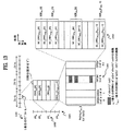
図13は、本発明の一実施例に係るフレーム構造を示すダイアグラムである。 FIG. 13 is a diagram illustrating a frame structure according to an embodiment of the present invention.
この実施例で、システム帯域1301は、N個の周波数パーティションFP0、FP1、…、FPi、…、FPN−1に分けられる。これら周波数パーティションは、部分周波数再使用又は他の目的のために使用される。周波数パーティションFPi 1302は、LDRU,FPi個の分散資源ユニットDRUFPi[j](j=0〜LDRU,FPi−1)、及び/又は、図13に示していないが、一つ以上のローカル資源ユニットを含むことができる。一つのDRUFPi[j]の時間長さは、フレームを構成する複数のサブフレームのそれぞれの時間長さと同一であるか、それより小さい。この実施例では、一つのDRUFPi[j]の時間長さが一つのサブフレームの時間長さと同一であるが、本発明がここに限定されることはない。t番目のサブフレーム1303及びDRUFPi[j]は、H個のOFDMシンボルからなる。l番目OFDMシンボル1304は、Psc個のサブキャリアからなるが、これに、nl個のパイロットサブキャリア及びLSC,l(=Psc−nl)個のデータサブキャリアが含まれる。nl個のパイロットサブキャリアを除けば、l番目のOFDMシンボル1304は、ブロック1305のように再び示される。ブロック1305のSC_DRUFPi[j],l[n](n=0、…、LSC,l−1)は、システム帯域のi番目の周波数パーティションのj番目のDRUのl番目のOFDMシンボルのn番目のサブキャリアを示す。
In this embodiment, the
図14は、本発明の一実施例によるサブキャリア―DRUマッピングを示すダイアグラムである。 FIG. 14 is a diagram illustrating subcarrier-DRU mapping according to an embodiment of the present invention.
図14の(b)は、図14の(a)に示すように、周波数パーティションFPi内に含まれた全てのDRUのl番目のOFDMシンボルのデータサブキャリアを示す。それぞれのDRUがLSC,l個のデータサブキャリアを含むので、周波数パーティションFPiは、総LDRU,FPi・LSC,l個のデータサブキャリアを含む。LDRU,FPi・LSC,l個のサブキャリアは、順次リナンバリングされ、インデックス0〜LDRU,FPi・LSC,l−1の値を有する。その次に、このように論理的に連続したリナンバリングされたデータサブキャリアは、LDRU,FPi・LSP,l個のペアにグルーピングされ、インデックス0〜LDRU,FPi・LSP,l−1まで再びリナンバリングされる。ここで、LSP,l=LSC,l/2である。それぞれのリナンバリングされたデータサブキャリアペアはRSPFPi,l[u]と表記されるが、これは、インデックス{SC_DRUFPi[j],l[2v],SC_DRUFPi[j],l[2v+1]}を有するサブキャリアペアを示す。このとき、0<=u<LDRU,FPi・LSP,l、j=floor(u/LSP,l)、v=u mod LSP,l.である。
FIG. 14B shows data subcarriers of the l-th OFDM symbol of all DRUs included in the frequency partition FP i as shown in FIG. 14A. Since each DRU includes L SC, l data subcarriers, the frequency partition FP i includes a total of L DRU, FPi · L SC, l data subcarriers. L DRU, FPi · L SC, l subcarriers are sequentially renumbered and have values of
図13及び図14は、本発明に係るフレーム構造の論理領域を示す。ペアをなしたサブキャリアRSPFPi,l[u]は、予め決定された公式によって周波数パーティションFPiの分散LRUにマッピングされる。物理領域での各PRUに対応する分散LRUは、基地局と移動通信端末との間で交換される。 13 and 14 show a logical area of the frame structure according to the present invention. The paired subcarriers RSP FPi, l [u] are mapped to the distributed LRU of the frequency partition FP i by a predetermined formula. Distributed LRU corresponding to each PRU in the physical area is exchanged between the base station and the mobile communication terminal.
本発明の一実施例によれば、前記予め決定されたパーミューテーション公式は、SC_DRUFPi[j]、l[m]=RSPFPi,l[k]のように与えられる。ここで、kは、LDRU,FPi・f(m,s)+g(PermSeq(),s,m,l,t)で、これは、t番目のサブフレームのs番目の分散LRUのl番目のOFDMAシンボルでのm番目のサブキャリアペアを意味し、mは、0からLSP,l−1の範囲を有するサブキャリアペアで、tは、そのフレームに該当するサブフレームインデックスを意味する。 According to an embodiment of the present invention, the predetermined permutation formula is given as SC_DRU FPi [j], l [m] = RSP FPi, l [k]. Here, k is L DRU, FPi · f (m, s) + g (PermSeq (), s, m, l, t), which is the lth of the sth distributed LRU of the tth subframe. , M is a subcarrier pair having a range from 0 to L SP, l −1, and t is a subframe index corresponding to the frame.
図15は、図6Bを含み、図2〜図14の各データ構造を交換可能な無線通信システムの構造を示す図である。この無線通信システムは、E―UMTS(evolved―universal mobile telecommunications system)のネットワーク構造を有することができる。また、E―UMTSは、LTE(long term evolution)システムといわれる。この無線通信システムは、音声、パケットデータなどの多様な通信サービスを提供するために幅広く採択される。 FIG. 15 is a diagram showing a structure of a wireless communication system including FIG. 6B and capable of exchanging the data structures of FIGS. This wireless communication system can have an E-UMTS (evolved-universal mobile telecommunications system) network structure. The E-UMTS is referred to as an LTE (Long Term Evolution) system. This wireless communication system is widely adopted to provide various communication services such as voice and packet data.
図15を参照すれば、E―UTRAN(evolved―UMTS terrestrial radio access network)は、制御プレーン及びユーザプレーンを提供する一つ以上のBS(Base station、基地局)20を有する。 Referring to FIG. 15, an E-UTRAN (evolved-UMTS terrestrial radio access network) includes one or more BSs (Base Stations) 20 that provide a control plane and a user plane.
ユーザ機器(User Equipment、UE)10は、固定又は移動可能であり、移動局(mobile station、MS)、ユーザ端末(user terminal、UT)、加入者局(subscriber station、SS)、無線機器などの他の用語で称される。BS20は、UE10と通信する、通常、固定された局であり、eNB(evolved node―B)、BTS(base transceiver system)、接続ポイント(access point)などの他の用語で称されることもある。BS20のカバレッジ内には一つ以上のセルが存在する。ユーザトラフィック又は制御トラフィックを送信するインターフェースは、各BS20間で使用される。以下、ダウンリンクはBS20からUE10への通信リンクとして定義され、アップリンクはUE10からBS20までの通信リンクとして定義される。
The user equipment (User Equipment, UE) 10 is fixed or movable, such as a mobile station (mobile station, MS), a user terminal (user terminal, UT), a subscriber station (subscriber station, SS), a radio equipment, etc. In other terms. The
各BS20は、X2インターフェースによって互いに連結される。また、各BS20は、S1インターフェースによってEPC(evolved packet core)に連結され、特に、MME(mobility management entity)/S―GW(serving gateway)30に連結される。S1インターフェースは、BS20とMME/S―GW30との間の多対多(many―to―many)連結をサポートする。
Each
図16は、装置50の各構成要素を示すダイアグラムである。この装置50は、図15のUE又はBSである。また、この装置50は、図2〜図14の各データ構造を交換することができる。装置50は、プロセッサ51、メモリ52、無線周波数ユニット(RFユニット)53、ディスプレイユニット54及びユーザインターフェースユニット55を含む。無線インターフェースプロトコルの各レイヤーは、プロセッサ51内で具現される。プロセッサ51は、制御プレーン及びユーザプレーンを提供する。各レイヤーの機能はプロセッサ51内で具現される。プロセッサ51は、競合解決タイマー(contention resolution timer)を含むことができる。メモリ52は、プロセッサ51に連結され、オペレーティングシステム、アプリケーション及び一般のファイルを格納する。装置50がUEである場合、ディスプレイユニット54は、多様な情報をディスプレイし、LCD(liquid crystal display)、OLED(organic light emitting diode)などのよく知られた要素を使用することができる。ユーザインターフェースユニット55は、キーパッド、タッチスクリーンなどのよく知られたユーザインターフェースの組み合わせで構成される。RFユニット53は、プロセッサ51に連結され、無線信号を送受信することができる。
FIG. 16 is a diagram showing each component of the
UEとネットワークとの間の無線インターフェースプロトコルの各レイヤーは、通信システムでよく知られたOSI(open system interconnection)モデルの下位3個のレイヤーに基づいて第1のレイヤー(L1)、第2のレイヤー(L2)及び第3のレイヤー(L3)に分類される。物理レイヤー又はPHYレイヤーは、前記第1のレイヤーに属し、物理チャンネルを介して情報伝送サービスを提供する。RRC(radio resource control)レイヤーは、前記第3のレイヤーに属し、UEとネットワークとの間の各制御無線資源を提供する。UEとネットワークは、RRCレイヤーを介して各RRCメッセージを交換する。 Each layer of the radio interface protocol between the UE and the network is divided into a first layer (L1) and a second layer based on the lower three layers of the OSI (open system interconnection) model well known in the communication system. (L2) and the third layer (L3). The physical layer or the PHY layer belongs to the first layer and provides an information transmission service through a physical channel. A radio resource control (RRC) layer belongs to the third layer and provides each control radio resource between the UE and the network. The UE and the network exchange each RRC message through the RRC layer.
この技術分野の熟練された者にとって、本発明の思想から逸脱しない範囲で本発明の多様な変形が可能であることは明白であろう。したがって、本発明は、添付した特許請求の範囲とその等価物の範囲内で多様な変形を行えるように意図された。 It will be apparent to those skilled in the art that various modifications of the present invention are possible without departing from the spirit of the invention. Accordingly, it is intended that the present invention be susceptible to various modifications within the scope of the appended claims and their equivalents.
本発明は、SFBCをサポートする広帯域無線移動通信システムに適用可能である。 The present invention is applicable to a broadband wireless mobile communication system that supports SFBC.
Claims (20)
移動局に1つ以上の資源ユニットを送信することであって、各資源ユニットは、18個のサブキャリア×複数のOFDMAシンボルで構成される、ことを包含し、
該1つ以上の資源ユニットは、X個の連続サブキャリア×1つのOFDMAシンボルをパーミュテーションユニットとして用いて順序を入れ替えられ、
該Xは、2の倍数であり、かつ18の約数であり、かつ18未満である正の整数である、方法。A method for transmitting a signal at a base station in a wireless communication system, comprising:
Transmitting one or more resource units to a mobile station, each resource unit comprising 18 subcarriers x multiple OFDMA symbols ,
The one or more resource units may be reordered using X consecutive subcarriers × one OFDMA symbol as a permutation unit ;
The X is a multiple of 2, and 18 is a divisor of, and is a positive integer less than 18, the method.
基地局から1つ以上の資源ユニットを受信することであって、各資源ユニットは、18個のサブキャリア×複数のOFDMAシンボルで構成される、ことを包含し、
該1つ以上の資源ユニットは、X個の連続サブキャリア×1つのOFDMAシンボルをパーミュテーションユニットとして用いて順序を入れ替えられ、
該Xは、2の倍数であり、かつ18の約数であり、かつ18未満である正の整数である、方法。A method for receiving a signal at a mobile station in a wireless communication system, comprising:
Receiving one or more resource units from a base station, each resource unit comprising 18 subcarriers x multiple OFDMA symbols ,
The one or more resource units may be reordered using X consecutive subcarriers × one OFDMA symbol as a permutation unit ;
The X is a multiple of 2, and 18 is a divisor of, and is a positive integer less than 18, the method.
メモリと、
該メモリに動作可能に接続され、1つ以上の資源ユニットを送信するように構成されるプロセッサであって、各資源ユニットは、18個のサブキャリア×複数のOFDMAシンボルで構成される、プロセッサと
を備え、
該1つ以上の資源ユニットは、X個の連続サブキャリア×1つのOFDMAシンボルをパーミュテーションユニットとして用いて順序を入れ替えられ、
該Xは、2の倍数であり、かつ18の約数であり、かつ18未満である正の整数である、装置。An apparatus configured to transmit a signal in a wireless communication system, the apparatus comprising:
Memory,
A processor operatively connected to the memory and configured to transmit one or more resource units, each resource unit comprising 18 subcarriers x multiple OFDMA symbols ; With
The one or more resource units may be reordered using X consecutive subcarriers × one OFDMA symbol as a permutation unit ;
The apparatus, wherein X is a positive integer that is a multiple of 2 and is a divisor of 18 and less than 18 .
メモリと、
該メモリに動作可能に接続され、1つ以上の資源ユニットを受信するように構成されるプロセッサであって、各資源ユニットは、18個のサブキャリア×複数のOFDMAシンボルで構成される、プロセッサと
を備え、
該1つ以上の資源ユニットは、X個の連続サブキャリア×1つのOFDMAシンボルをパーミュテーションユニットとして用いて順序を入れ替えられ、
該Xは、2の倍数であり、かつ18の約数であり、かつ18未満である正の整数である、装置。An apparatus configured to receive a signal in a wireless communication system, the apparatus comprising:
Memory,
A processor operatively connected to the memory and configured to receive one or more resource units, each resource unit comprising 18 subcarriers x multiple OFDMA symbols ; With
The one or more resource units may be reordered using X consecutive subcarriers × one OFDMA symbol as a permutation unit ;
The apparatus, wherein X is a positive integer that is a multiple of 2 and is a divisor of 18 and less than 18 .
Applications Claiming Priority (11)
| Application Number | Priority Date | Filing Date | Title |
|---|---|---|---|
| US4405908P | 2008-04-11 | 2008-04-11 | |
| US61/044,059 | 2008-04-11 | ||
| US4741708P | 2008-04-23 | 2008-04-23 | |
| US61/047,417 | 2008-04-23 | ||
| US5135908P | 2008-05-08 | 2008-05-08 | |
| US61/051,359 | 2008-05-08 | ||
| US5446108P | 2008-05-19 | 2008-05-19 | |
| US61/054,461 | 2008-05-19 | ||
| KR10-2009-0028898 | 2009-04-03 | ||
| KR1020090028898A KR101571726B1 (en) | 2008-04-11 | 2009-04-03 | A method for designing mini resource unit and transmission for a distributed resource unit in consideration of space frequency block code |
| PCT/KR2009/001814 WO2009125978A2 (en) | 2008-04-11 | 2009-04-08 | A method for designing mini resource unit and transmission for a distributed resource unit in consideration of space frequency block code |
Publications (3)
| Publication Number | Publication Date |
|---|---|
| JP2011519187A JP2011519187A (en) | 2011-06-30 |
| JP2011519187A5 JP2011519187A5 (en) | 2011-08-11 |
| JP5198583B2 true JP5198583B2 (en) | 2013-05-15 |
Family
ID=41162391
Family Applications (1)
| Application Number | Title | Priority Date | Filing Date |
|---|---|---|---|
| JP2010547575A Expired - Fee Related JP5198583B2 (en) | 2008-04-11 | 2009-04-08 | Mini resource design and transmission method for distributed resource units considering spatial frequency |
Country Status (6)
| Country | Link |
|---|---|
| US (1) | US8218662B2 (en) |
| EP (1) | EP2181535A4 (en) |
| JP (1) | JP5198583B2 (en) |
| KR (1) | KR101571726B1 (en) |
| CN (1) | CN102084630B (en) |
| WO (1) | WO2009125978A2 (en) |
Families Citing this family (21)
| Publication number | Priority date | Publication date | Assignee | Title |
|---|---|---|---|---|
| CN101296022B (en) * | 2007-04-24 | 2012-09-26 | 展讯通信(上海)有限公司 | Condition code distribution method of E-HICH channel |
| KR101498060B1 (en) * | 2008-02-19 | 2015-03-03 | 엘지전자 주식회사 | Method for uplink transmittion in an ofdm(a) system |
| US7952989B2 (en) * | 2008-04-09 | 2011-05-31 | Nokia Siemens Networks Oy | Permuting slots to logical distributed resource units |
| US20100002641A1 (en) | 2008-07-04 | 2010-01-07 | Nokia Siemens Networks Oy | Support for broadcast control header for wireless networks |
| WO2010018643A1 (en) * | 2008-08-12 | 2010-02-18 | 株式会社日立コミュニケーションテクノロジー | Radio communication system, radio communication device, and radio resource management method |
| WO2010047510A2 (en) * | 2008-10-20 | 2010-04-29 | Lg Electronics Inc. | Method and apparatus for transmitting signal in a wireless communication system |
| WO2010047511A2 (en) * | 2008-10-20 | 2010-04-29 | Lg Electronics Inc. | Method and apparatus for transmitting signal in a wireless communication system |
| US8560696B2 (en) * | 2009-04-28 | 2013-10-15 | Intel Corporation | Transmission of advanced-MAP information elements in mobile networks |
| US20110053627A1 (en) * | 2009-08-28 | 2011-03-03 | Samsung Electronics Co., Ltd. | System and method for efficient indication of distributed sub-band resources |
| CN102111878B (en) * | 2009-12-28 | 2014-12-10 | 中兴通讯股份有限公司 | Resource index coding method and base station in wireless communication system |
| KR101757452B1 (en) * | 2010-01-08 | 2017-07-13 | 삼성전자주식회사 | A method for mapping and demapping resource in a wireless communication system and an apparatus thereof |
| KR20110083519A (en) * | 2010-01-12 | 2011-07-20 | 엘지전자 주식회사 | Method and apparatus of allocating resource for enhanced multicast broadcast service data |
| KR101655269B1 (en) * | 2010-05-28 | 2016-09-07 | 삼성전자주식회사 | Apparatus and method for resource segmetation in wireless communication system |
| US9716579B2 (en) * | 2014-08-19 | 2017-07-25 | Intel IP Corporation | Subcarrier allocations for operation in mixed bandwidth environments |
| CN107113829B (en) * | 2014-10-09 | 2020-07-17 | Lg电子株式会社 | Method and apparatus for allocating radio resources according to resource allocation setting in W L AN |
| US10476641B2 (en) * | 2015-11-17 | 2019-11-12 | Qualcomm Incorporated | Back-to-back reference signals |
| CN113225115A (en) * | 2016-05-12 | 2021-08-06 | 松下电器(美国)知识产权公司 | Receiving method, station and integrated circuit for reception |
| WO2020237573A1 (en) * | 2019-05-30 | 2020-12-03 | Qualcomm Incorporated | Mapping one preamble to multiple physical uplink shared channel resource units for two-step random access procedure |
| US10912003B1 (en) * | 2019-09-27 | 2021-02-02 | Fortinet, Inc. | Spectral efficient selection of station clusters for concurrent data transmissions in high efficiency WLANs (wireless local access networks) using unsupervised machine learning models |
| US11870735B2 (en) * | 2020-07-28 | 2024-01-09 | Mediatek Singapore Pte. Ltd. | Simplification for distributed-tone resource units in 6GHz low-power indoor systems |
| US11818698B2 (en) * | 2021-05-17 | 2023-11-14 | Qualcomm Incorporated | Distributed resource unit transmission |
Family Cites Families (11)
| Publication number | Priority date | Publication date | Assignee | Title |
|---|---|---|---|---|
| JP4832444B2 (en) * | 2004-10-18 | 2011-12-07 | エルジー エレクトロニクス インコーポレイティド | Feedback information transmission method in OFDM or OFDMA mobile communication system |
| KR100866210B1 (en) * | 2005-01-03 | 2008-10-30 | 삼성전자주식회사 | Method and system for service provide using same frequency in a wireless communication systems |
| KR100698770B1 (en) * | 2005-03-09 | 2007-03-23 | 삼성전자주식회사 | Apparatus and method for subcarrier mapping of stc data in broadband wireless communication system |
| KR100981495B1 (en) | 2005-10-12 | 2010-09-10 | 삼성전자주식회사 | Method and apparatus for transmitting data in a communication system |
| CN1988434B (en) * | 2005-12-19 | 2011-07-27 | 株式会社Ntt都科摩 | Pilot frequency sub carrier grouping method in orthogonal frequency division multiple access system |
| RU2304355C1 (en) | 2006-01-12 | 2007-08-10 | Самсунг Электроникс Ко., Лтд. | Method for adaptive data transfer in wireless network using ieee.802.16 standard |
| CN101043495A (en) * | 2006-03-20 | 2007-09-26 | 北京三星通信技术研究有限公司 | Device and method for dividing resource blocks of wireless communication system |
| CN101072216B (en) * | 2006-05-10 | 2010-09-15 | 华为技术有限公司 | Resource distribution and transceiving method and device for orthogonal frequency division multi address accessing system |
| KR20080086780A (en) * | 2007-03-23 | 2008-09-26 | 삼성전자주식회사 | Method for allocating data burst in wireless mobile communication system |
| KR101438220B1 (en) * | 2007-07-13 | 2014-09-05 | 엘지전자 주식회사 | Method for allocating radio resource in wireless communication system and method for transmitting or receiving data using the same |
| US7907572B2 (en) * | 2007-09-28 | 2011-03-15 | Intel Corporation | Collocated radio coexistence method |
-
2009
- 2009-04-03 KR KR1020090028898A patent/KR101571726B1/en not_active IP Right Cessation
- 2009-04-08 JP JP2010547575A patent/JP5198583B2/en not_active Expired - Fee Related
- 2009-04-08 CN CN200980100621.4A patent/CN102084630B/en not_active Expired - Fee Related
- 2009-04-08 EP EP09730590A patent/EP2181535A4/en not_active Withdrawn
- 2009-04-08 WO PCT/KR2009/001814 patent/WO2009125978A2/en active Application Filing
- 2009-04-10 US US12/421,904 patent/US8218662B2/en not_active Expired - Fee Related
Also Published As
| Publication number | Publication date |
|---|---|
| CN102084630A (en) | 2011-06-01 |
| WO2009125978A3 (en) | 2010-01-14 |
| KR20090108536A (en) | 2009-10-15 |
| KR101571726B1 (en) | 2015-11-25 |
| EP2181535A2 (en) | 2010-05-05 |
| WO2009125978A2 (en) | 2009-10-15 |
| US8218662B2 (en) | 2012-07-10 |
| CN102084630B (en) | 2014-10-08 |
| EP2181535A4 (en) | 2010-12-15 |
| JP2011519187A (en) | 2011-06-30 |
| US20090285168A1 (en) | 2009-11-19 |
Similar Documents
| Publication | Publication Date | Title |
|---|---|---|
| JP5198583B2 (en) | Mini resource design and transmission method for distributed resource units considering spatial frequency | |
| JP5580398B2 (en) | Method and system for mapping pilot signals in multi-stream transmission | |
| US8369206B2 (en) | Cell-specific shifting of reference signals in multi-stream transmissions | |
| CA2766062C (en) | Reference signal design for wireless communication system | |
| US8259643B2 (en) | Apparatus and method for codeword to layer mapping in MIMO transmission wireless systems | |
| JP5379141B2 (en) | Wireless communication system using pilot subcarrier allocation | |
| CN102349336B (en) | For the method and apparatus that the adjacent-channel interference in access point base station suppresses | |
| RU2504077C2 (en) | Correcting sequence for wireless networks | |
| US20200366435A1 (en) | Flexible transmission of messages in a wireless communication system with multiple transmit antennas | |
| JP5612564B2 (en) | Permutation apparatus and method with improved resource granularity in wireless communication | |
| JP5174925B2 (en) | How to design a multiplexing structure for resource allocation to support legacy systems | |
| US9860099B1 (en) | Support of frequency diversity mode for block code based transmission in OFDMA | |
| CN101990750B (en) | Wireless communication system with multiple transmission antennas using pilot subcarrier allocation | |
| US10873432B2 (en) | Apparatus and method for locating of phase tracking reference signal in wireless communication system | |
| US8503420B2 (en) | Physical structure and design of sounding channel in OFDMA systems | |
| JP2013501400A (en) | Replacement zones for multipoint collaboration systems | |
| RU2438259C1 (en) | Method for designing mini resource unit and transmission for distributed resource unit in consideration of space frequency block code | |
| RU2445745C1 (en) | Wireless communication system with multiple transmitting antennae using pilot signal subcarrier allocation | |
| Pelcat et al. | 3GPP long term evolution | |
| KR101667424B1 (en) | Method and apparatus of transmitting midamble in wireless communication system | |
| KR101667423B1 (en) | Method and apparatus of transmitting midamble in wireless communication system | |
| KR20100004040A (en) | A method of transmitting a control signal in a wireless communication system |
Legal Events
| Date | Code | Title | Description |
|---|---|---|---|
| A521 | Written amendment |
Free format text: JAPANESE INTERMEDIATE CODE: A523 Effective date: 20110624 |
|
| A131 | Notification of reasons for refusal |
Free format text: JAPANESE INTERMEDIATE CODE: A131 Effective date: 20120613 |
|
| A521 | Written amendment |
Free format text: JAPANESE INTERMEDIATE CODE: A523 Effective date: 20120809 |
|
| TRDD | Decision of grant or rejection written | ||
| A01 | Written decision to grant a patent or to grant a registration (utility model) |
Free format text: JAPANESE INTERMEDIATE CODE: A01 Effective date: 20130108 |
|
| A61 | First payment of annual fees (during grant procedure) |
Free format text: JAPANESE INTERMEDIATE CODE: A61 Effective date: 20130206 |
|
| FPAY | Renewal fee payment (event date is renewal date of database) |
Free format text: PAYMENT UNTIL: 20160215 Year of fee payment: 3 |
|
| R150 | Certificate of patent or registration of utility model |
Free format text: JAPANESE INTERMEDIATE CODE: R150 |
|
| R250 | Receipt of annual fees |
Free format text: JAPANESE INTERMEDIATE CODE: R250 |
|
| R250 | Receipt of annual fees |
Free format text: JAPANESE INTERMEDIATE CODE: R250 |
|
| LAPS | Cancellation because of no payment of annual fees |