JP5195388B2 - Power storage device - Google Patents
Power storage device Download PDFInfo
- Publication number
- JP5195388B2 JP5195388B2 JP2008320440A JP2008320440A JP5195388B2 JP 5195388 B2 JP5195388 B2 JP 5195388B2 JP 2008320440 A JP2008320440 A JP 2008320440A JP 2008320440 A JP2008320440 A JP 2008320440A JP 5195388 B2 JP5195388 B2 JP 5195388B2
- Authority
- JP
- Japan
- Prior art keywords
- voltage
- power storage
- discharge
- storage unit
- time
- Prior art date
- Legal status (The legal status is an assumption and is not a legal conclusion. Google has not performed a legal analysis and makes no representation as to the accuracy of the status listed.)
- Active
Links
Images


Description
本発明は、蓄電部に電力を蓄え、必要な時に放電する蓄電装置に関するものである。 The present invention relates to a power storage device that stores power in a power storage unit and discharges it when necessary.
近年、環境への配慮や燃費向上のために停車時にエンジン駆動を停止するアイドリングストップ機能を搭載した自動車(以下、車両という)が市販されている。このような車両は使用中に断続的に大電流を消費するスタータが駆動すると一時的にバッテリの電圧が下がる。その結果、オーディオやカーナビゲーション等の他の負荷への供給電圧も下がり、その動作が不安定になる可能性があった。 2. Description of the Related Art In recent years, automobiles (hereinafter referred to as vehicles) equipped with an idling stop function for stopping engine driving when the vehicle is stopped for environmental considerations and fuel efficiency improvement are on the market. In such a vehicle, when a starter that consumes a large current intermittently during use is driven, the voltage of the battery temporarily drops. As a result, the supply voltage to other loads such as audio and car navigation also decreases, and the operation may become unstable.
また、車両の制動についても、従来の機械的な油圧制御から電気的な油圧制御への各種車両制動システムの提案がなされてきているが、バッテリが異常になった時、車両制動システムが動作しなくなる等の可能性があった。 Also, regarding vehicle braking, various vehicle braking systems from conventional mechanical hydraulic control to electrical hydraulic control have been proposed, but when the battery becomes abnormal, the vehicle braking system operates. There was a possibility of disappearing.
これらに対し、一時的なバッテリの電圧低下時に負荷に十分な電力を供給したり、バッテリ異常時に車両制動システムに電力を供給するための補助電源としての蓄電装置が、例えば特許文献1に提案されている。なお、特許文献1は蓄電装置の内、特にバッテリ異常時に車両制動システムの電子制御部へ電力を供給する電源バックアップユニットとして示されている。
On the other hand, for example,
図10はこのような蓄電装置のブロック回路図である。電力を蓄える蓄電素子には例えば大容量の電気二重層キャパシタが用いられ、これを複数個接続して蓄電部としてのキャパシタユニット101が構成されている。キャパシタユニット101には、その充放電を制御する充電回路103、および放電回路105が接続されている。充電回路103と放電回路105はマイコン107によって制御されている。マイコン107にはバッテリ異常を検出するためのバッテリ電圧検出手段109が接続され、バッテリ電圧検出手段109には異常時にキャパシタユニット101の電力を供給するFETスイッチ111が接続されている。
FIG. 10 is a block circuit diagram of such a power storage device. For example, a large-capacity electric double layer capacitor is used as a power storage element that stores electric power, and a plurality of these are connected to form a
このようにして構成された電源バックアップユニットとしての蓄電装置113はバッテリ115と電子制御部117の間に接続されており、イグニションスイッチ119によって起動、停止するように制御されている。
The
電子制御部117は車両制動システムであるので、安全確保のためにバッテリ115が異常になっても電子制御部117を駆動させ続けなければならない。そこで、バッテリ115の異常をバッテリ電圧検出手段109が検出すれば、FETスイッチ111をオンにしてキャパシタユニット101の電力を電子制御部117に供給することで、バッテリ115の異常に対応している。
Since the electronic control unit 117 is a vehicle braking system, the electronic control unit 117 must be continuously driven even when the
なお、バッテリ115が正常な状態で車両の使用を終了すると、キャパシタユニット101には電力が蓄えられたままの状態となる。これをこのまま車両非使用時に放置しておくと、自己放電により徐々にキャパシタユニット101の電圧が低下していくものの、キャパシタユニット101を構成する電気二重層キャパシタに定格電圧近傍の電圧が長期間印加されたままとなるため、電気二重層キャパシタの劣化が進行してしまい、キャパシタユニット101の寿命が短くなる。そこで、これを避けるために、マイコン107は車両使用終了時に放電回路105を制御してキャパシタユニット101の電力を強制的に放電している。これにより、蓄電装置113の長寿命化を実現している。
上記の蓄電装置113によると、確かにバッテリ115の異常時に電子制御部117を駆動させ続けられるので、車両制動システムの安全性を確保できるとともに、使用終了時にキャパシタユニット101を放電することで長寿命化が図れるのであるが、車両使用開始毎にキャパシタユニット101を満充電にする必要があり、起動完了までに時間がかかっていた。
According to the
そこで、起動時間を短縮するために、電気二重層キャパシタの劣化が進行しない程度の電圧までキャパシタユニット101の電力を放電する構成が考えられる。これにより、キャパシタユニット101を完全放電してしまうよりも早く起動を完了することができる。
Therefore, in order to shorten the startup time, a configuration in which the power of the
このような動作を実現するためには、あらかじめキャパシタユニット101の劣化がほとんど進行しない電圧(以下、非劣化電圧Vhと呼び、ここでは6Vとした)を基にキャパシタユニット101の強制放電を終了する電圧値を放電終端電圧Vdとして求めてマイコン107に記憶しておき、車両使用終了時にキャパシタユニット101の電圧が放電終端電圧Vdに至るまで放電回路105により放電するようにすればよい。
In order to realize such an operation, the forced discharge of the
しかし、キャパシタユニット101の使用状況により自己放電特性が異なるため、放電終端電圧Vdの値によっては、以下のような課題があった。
However, since the self-discharge characteristics differ depending on the usage state of the
まず、放電終端電圧Vdがキャパシタユニット101の既定電圧Vm(ここでは満充電電圧とし、具体的には13Vとした)に近い場合、すなわち放電終端電圧Vdmaxまで強制放電する場合について図11を参照しながら説明する。なお、図11において、横軸は時刻tを、縦軸はキャパシタユニット101の電圧Vcを、それぞれ示す。
First, a case where the discharge termination voltage Vd is close to the predetermined voltage Vm (here, full charge voltage, specifically 13 V) of the
図11において、時刻t2で車両の使用が終了したとする。それまではキャパシタユニット101には電力が蓄えられているので、その電圧Vcは既定電圧Vmで安定している。
In FIG. 11, it is assumed that the use of the vehicle is finished at time t2. Until then, electric power is stored in the
ここで、図11の太実線で示した特性は、キャパシタユニット101が既定電圧Vmに至っている期間tsが短いものを、太点線で示した特性は期間tsが長いものを、それぞれ示す。従って、太実線で示した特性の場合は、時刻t1からt2の間が期間tsになり、時刻t1より以前はキャパシタユニット101が充電中であることを示す。
Here, the characteristic indicated by the thick solid line in FIG. 11 indicates that the period ts when the
一方、太点線で示した特性の場合は、時刻t0からt2の間が期間tsになり、太実線の特性の場合に比べ期間tsが長いことになる。 On the other hand, in the case of the characteristic indicated by the thick dotted line, the period ts is between the times t0 and t2, and the period ts is longer than that in the case of the thick solid line characteristic.
これら2種類の状態におけるキャパシタユニット101の強制放電以降の特性について以下に説明する。時刻t2からt3までに放電回路105により、キャパシタユニット101の電圧Vcが放電終端電圧Vdmaxまで放電されたとする。なお、時刻t2でキャパシタユニット101の内部抵抗値と放電電流の積により決まる電圧幅ΔVだけ電圧Vcが低下する。時刻t2からt3における電圧低下速度(傾き)は放電回路105により制御されているので、太実線の場合も太点線の場合もほぼ同じ特性となる。
The characteristics after the forced discharge of the
その後、時刻t3で電圧Vcが放電終端電圧Vdmaxに至ると、マイコン107は放電回路105の動作を停止し、強制放電を終了する。これにより、前記電圧幅ΔVだけ電圧Vcが上昇する。それ以降はキャパシタユニット101の自己放電により、電圧Vcが経時的に低下していく。この時、期間tsが短い時は太実線の特性に示すように自己放電による電圧Vcの低下が速く、期間tsが長い時は太点線の特性に示すように自己放電による電圧Vcの低下が遅くなる。なお、この理由は後述する。
Thereafter, when the voltage Vc reaches the discharge termination voltage Vdmax at time t3, the microcomputer 107 stops the operation of the
このような特性により、期間tsが短い時は速やかに電圧Vcが低下して、非劣化電圧Vh(6V)に接近するため、キャパシタユニット101の長寿命化を図ることが可能となる。しかし、期間tsが長い時は電圧Vcが徐々に低下するため、なかなか非劣化電圧Vh(6V)に接近しない。その結果、キャパシタユニット101が高電圧状態にある期間が長くなり、長寿命化が図れなくなるという課題があった。
With such characteristics, when the period ts is short, the voltage Vc quickly decreases and approaches the non-degraded voltage Vh (6 V), so that the life of the
そこで、次に放電終端電圧Vdがキャパシタユニット101の既定電圧Vmから離れている場合、すなわち放電終端電圧Vdminまで強制放電する場合について図12を参照しながら説明する。なお、図12において、横軸と縦軸の意味は図11と同じである。
Then, the case where the discharge termination voltage Vd is separated from the predetermined voltage Vm of the
図12において、時刻t0からt2までの動作は図11と同じであるので説明を省略する。次に、時刻t2において車両の使用が終了して、キャパシタユニット101を強制放電する際の特性について以下に説明する。時刻t2からt3までに放電回路105により、キャパシタユニット101の電圧Vcが放電終端電圧Vdminまで放電されるのであるが、その傾きは図11の場合と同様に、太実線の場合も太点線の場合もほぼ同じ特性となる。また、時刻t2で電圧幅ΔVだけ電圧Vcが低下するのも同様である。
In FIG. 12, the operation from time t0 to t2 is the same as that in FIG. Next, characteristics when the use of the vehicle ends at time t2 and the
その後、時刻t3で電圧Vcが放電終端電圧Vdminに至ると、強制放電が終了する。これにより、前記電圧幅ΔVだけ電圧Vcが上昇する。それ以降はキャパシタユニット101の自己放電により、電圧Vcが経時的に低下していく。この時の低下速度は、図11の場合と同様に、期間tsが短い時は太実線の特性に示すように電圧Vcの低下が速く、期間tsが長い時は太点線の特性に示すように電圧Vcの低下が遅くなる。
Thereafter, when the voltage Vc reaches the discharge termination voltage Vdmin at time t3, the forced discharge ends. As a result, the voltage Vc increases by the voltage width ΔV. Thereafter, the voltage Vc decreases with time due to self-discharge of the
このような特性により、期間tsが長い時は電圧Vcが徐々に低下して非劣化電圧Vh(6V)に接近していくため、キャパシタユニット101の長寿命化を図ることが可能となる。しかし、期間tsが短い時は速やかに電圧Vcが低下するため、非劣化電圧Vh(6V)よりもさらに低い電圧に至る。これにより、キャパシタユニット101の寿命が短くなることはないが、再起動時にキャパシタユニット101の電圧Vcが必要以上に低下しているので、キャパシタユニット101を満充電するための起動時間が長くなるという課題があった。
With such characteristics, when the period ts is long, the voltage Vc gradually decreases and approaches the non-degraded voltage Vh (6 V), so that the life of the
ここで、期間tsの長短により自己放電特性が変化する理由について、図13を用いて説明する。図13はキャパシタの等価回路図を示す。ここで、前記したようにキャパシタユニット101は複数の電気二重層キャパシタを接続した構造であるが、ここでは接続された電気二重層キャパシタを合成して1つのキャパシタと等価として扱う。
Here, the reason why the self-discharge characteristic changes depending on the length of the period ts will be described with reference to FIG. FIG. 13 shows an equivalent circuit diagram of the capacitor. Here, as described above, the
図13に示すように、キャパシタは内部抵抗成分121、122、123・・・と容量成分131、132、133・・・が複数並列に接続された構成と等価であると考えられる。ここで、期間tsが短ければ、図13の一番上に示す容量成分131に電力が主に蓄えられ、並列接続された他の容量成分132、133・・・にはあまり充電されない。これは、図13の下方に示す容量成分132、133・・・になる程、内部抵抗成分121、122、123・・・の合成抵抗値が大きくなるためである。しかし、期間tsが長くなる程、徐々に容量成分132、133・・・にも充電されていく。従って、期間tsが短いと充電深度が浅く、長いと深いことになる。
As shown in FIG. 13, the capacitor is considered to be equivalent to a configuration in which a plurality of
この結果、期間tsが短い、すなわち充電深度が浅い状態のキャパシタでは、容量成分132、133・・・にはあまり充電されておらず、主に容量成分131に充電されているので、自己放電による電圧低下が速くなる。一方、期間tsが長い、すなわち充電深度が深い状態のキャパシタでは、容量成分132、133・・・にも充電されているので、自己放電による電圧低下が遅くなる。
As a result, in a capacitor with a short period ts, that is, with a shallow charging depth, the
以上のことから、放電終端電圧Vdをキャパシタユニット101の既定電圧Vmに近い値として設定すれば、キャパシタユニット101が満充電されている期間tsが長い場合、車両非使用時に高電圧印加状態が続き劣化が進行する可能性があり、放電終端電圧Vdを既定電圧Vmから離れた値として設定すれば、期間tsが短い場合、自己放電が進行して電圧Vcが必要以上に低下し、起動時間が長くなるという課題があった。これは、放電終端電圧Vdを一定値として決定したためである。従って、従来の構成では、キャパシタユニット101の長寿命化と蓄電装置113の高速起動を両立することができないという課題があった。
From the above, if the discharge termination voltage Vd is set to a value close to the predetermined voltage Vm of the
本発明は、前記従来の課題を解決するもので、蓄電部の長寿命化と高速起動を両立することができる蓄電装置を提供することを目的とする。 SUMMARY OF THE INVENTION The present invention solves the above-described conventional problems, and an object thereof is to provide a power storage device that can achieve both a long life and high-speed startup of a power storage unit.
前記従来の課題を解決するために、本発明の蓄電装置は、キャパシタからなる蓄電部と、前記蓄電部の電圧(Vc)を検出する電圧検出回路と、前記蓄電部を強制放電する放電回路と、前記電圧検出回路と前記放電回路に接続される制御回路と、を備え、前記制御回路は、前記蓄電部の電圧(Vc)を放電終端電圧(Vd)まで前記強制放電させた後、前記蓄電部を自己放電させるものであり、前記蓄電部の前記自己放電による前記蓄電部の電圧(Vc)の低下が速い状態となるほど前記放電終端電圧(Vd)を大きくするように制御するようにしたものである。
また、制御回路は、前記蓄電部の自己放電特性を変化させるパラメータ又は自己放電特性のパラメータの値を求め、前記パラメータと前記放電終端電圧(Vd)との相関関係にもとづき、前記放電終端電圧(Vd)を制御するものである。
また、蓄電装置は、キャパシタからなる蓄電部と、前記蓄電部を放電する放電回路と、前記放電回路に接続されるとともに、使用開始時と使用終了時の期間(ts)を計測するタイマーを備えた制御回路と、から構成され、前記制御回路は、使用終了後に、前記期間(ts)に応じて決定される放電終端電圧(Vd)まで前記蓄電部を放電するように前記放電回路を制御するようにし、自己放電特性を変化させる前記パラメータを前記期間(ts)としたものである。
In order to solve the conventional problems, a power storage device of the present invention includes a power storage unit including a capacitor, a voltage detection circuit that detects a voltage (Vc) of the power storage unit, and a discharge circuit that forcibly discharges the power storage unit. The voltage detection circuit and a control circuit connected to the discharge circuit, the control circuit forcibly discharging the voltage (Vc) of the power storage unit to a discharge termination voltage (Vd), and then storing the power storage Part is self-discharged, and the discharge termination voltage (Vd) is controlled to increase as the voltage (Vc) of the power storage part decreases rapidly due to the self-discharge of the power storage part. It is.
Further, the control circuit obtains a parameter for changing the self-discharge characteristic of the power storage unit or a parameter value of the self-discharge characteristic, and based on a correlation between the parameter and the discharge termination voltage (Vd), the discharge termination voltage ( Vd) is controlled.
The power storage device includes a power storage unit including a capacitor, a discharge circuit that discharges the power storage unit, and a timer that is connected to the discharge circuit and measures a period (ts) at the start and end of use. And the control circuit controls the discharge circuit to discharge the power storage unit up to a discharge termination voltage (Vd) determined according to the period (ts) after the use ends. Thus, the parameter for changing the self-discharge characteristic is the period (ts).
また、蓄電装置は、キャパシタからなる蓄電部と、前記蓄電部を放電する放電回路と、前記蓄電部の電圧(Vc)を検出する電圧検出回路と、前記放電回路、および前記電圧検出回路に接続されるとともに、使用開始時と使用終了時の期間(ts)を計測するタイマーを備えた制御回路と、から構成され、前記制御回路は、使用終了後に、前記期間(ts)における前記蓄電部の電圧(Vc)の積分値(Vt)に応じて決定される放電終端電圧(Vd)まで前記蓄電部を放電するように前記放電回路を制御するようにし、自己放電特性を変化させる前記パラメータを前記積分値(Vt)としたものである。 The power storage device is connected to a power storage unit including a capacitor, a discharge circuit that discharges the power storage unit, a voltage detection circuit that detects a voltage (Vc) of the power storage unit, the discharge circuit, and the voltage detection circuit And a control circuit having a timer for measuring a period (ts) at the start of use and at the end of use. The control circuit is configured to control the power storage unit in the period (ts) after the end of use. The discharge circuit is controlled to discharge the power storage unit to a discharge termination voltage (Vd) determined according to an integrated value (Vt) of the voltage (Vc), and the parameter for changing the self-discharge characteristic is It is an integral value (Vt).
また、蓄電装置は、キャパシタからなる蓄電部と、前記蓄電部を放電する放電回路と、前記蓄電部の電圧(Vc)を検出する電圧検出回路と、前記放電回路および前記電圧検出回路に接続された制御回路と、から構成され、前記制御回路は、使用終了後に前記電圧検出回路で検出した前記蓄電部の電圧(Vc)を少なくとも2点検出することにより、前記蓄電部の単位時間当たりの電圧変化率(Vk)を求め、前記電圧変化率(Vk)に応じて決定される放電終端電圧(Vd)まで前記蓄電部を放電するように前記放電回路を制御するようにし、自己放電特性の前記パラメータを前記電圧変化率(Vk)としたものである。 The power storage device is connected to a power storage unit including a capacitor, a discharge circuit that discharges the power storage unit, a voltage detection circuit that detects a voltage (Vc) of the power storage unit, the discharge circuit, and the voltage detection circuit. A voltage per unit time of the power storage unit by detecting at least two points of the voltage (Vc) of the power storage unit detected by the voltage detection circuit after the end of use. The rate of change (Vk) is obtained, the discharge circuit is controlled to discharge the power storage unit to a discharge termination voltage (Vd) determined according to the voltage rate of change (Vk), and the self-discharge characteristic The parameter is the voltage change rate (Vk).
本発明の蓄電装置によれば、蓄電部の長寿命化と高速起動を両立することができる蓄電装置を実現できるという効果が得られる。
また、期間(ts)に応じて放電終端電圧(Vd)を決定するので、強制放電後の自己放電による蓄電部の電圧(Vc)を非劣化電圧(Vh)に近づけることができる。その結果、蓄電部の高電圧印加状態が続いたり、起動に時間がかかる程度まで自己放電してしまうことを避けることができ、蓄電部の長寿命化と高速起動を両立することができる蓄電装置を実現できるという効果が得られる。
According to the power storage device of the present invention, there is an effect that it is possible to realize a power storage device that can achieve both a long life of the power storage unit and high-speed startup.
Further, since the discharge termination voltage (Vd) is determined according to the period (ts), the voltage (Vc) of the power storage unit due to self-discharge after forced discharge can be brought close to the non-degraded voltage (Vh). As a result, it is possible to avoid a situation where the high voltage application state of the power storage unit continues or self-discharge to the extent that it takes time to start up, and a power storage device capable of achieving both a long life and high speed startup of the power storage unit The effect that can be realized is obtained.
また、上記期間(ts)に替わって、期間(ts)における蓄電部の電圧(Vc)の積分値(Vt)に応じて放電終端電圧(Vd)を決定するので、期間(ts)の間に蓄電部の電圧(Vc)が変化しても、その間、蓄電部に蓄えられたエネルギーに相当する積分値(Vt)に応じて放電終端電圧(Vd)が決められる。従って、より正確な放電終端電圧(Vd)により、蓄電部の長寿命化と高速起動を両立することができる蓄電装置を実現できるという効果が得られる。 In addition , instead of the period (ts), the discharge termination voltage (Vd) is determined according to the integrated value (Vt) of the voltage (Vc) of the power storage unit in the period (ts), so during the period (ts) Even if the voltage (Vc) of the power storage unit changes, the discharge termination voltage (Vd) is determined according to the integrated value (Vt) corresponding to the energy stored in the power storage unit. Therefore, it is possible to achieve an effect of realizing a power storage device that can achieve both a long life of the power storage unit and high-speed startup by a more accurate discharge termination voltage (Vd).
また、蓄電装置によれば、上記期間(ts)に替わって、使用終了後の蓄電部の電圧(Vc)の電圧変化率(Vk)に応じて放電終端電圧(Vd)を決定するので、期間(ts)の間における蓄電部の電圧(Vc)の変化に影響されずに放電終端電圧(Vd)が決められる。従って、より正確な放電終端電圧(Vd)により、蓄電部の長寿命化と高速起動を両立することができる蓄電装置を実現できるという効果が得られる。 In addition , according to the power storage device, instead of the period (ts), the discharge termination voltage (Vd) is determined according to the voltage change rate (Vk) of the voltage (Vc) of the power storage unit after the end of use. The discharge termination voltage (Vd) is determined without being affected by the change in the voltage (Vc) of the power storage unit during (ts). Therefore, it is possible to achieve an effect of realizing a power storage device that can achieve both a long life of the power storage unit and high-speed startup by a more accurate discharge termination voltage (Vd).
以下、本発明を実施するための最良の形態について図面を参照しながら説明する。なお、以下の説明では蓄電装置を車両制動システムの電源バックアップユニットとして適用した場合について述べる。 The best mode for carrying out the present invention will be described below with reference to the drawings. In the following description, a case where the power storage device is applied as a power backup unit for a vehicle braking system will be described.
(実施の形態1)
図1は、本発明の実施の形態1における蓄電装置のブロック回路図である。図2は、本発明の実施の形態1における蓄電装置の蓄電部に電圧が印加される期間tsに対する放電終端電圧Vdの相関図である。図3は、本発明の実施の形態1における蓄電装置の蓄電部の電圧Vcにおける経時変化図である。図4は、本発明の実施の形態1における蓄電装置の蓄電部の温度Tに対する内部抵抗値Rの特性図である。図5は、本発明の実施の形態1における蓄電装置の蓄電部の温度Tに対する容量値Cの特性図である。なお、図1において太線は電力系配線を、細線は信号系配線をそれぞれ示す。
(Embodiment 1)
1 is a block circuit diagram of a power storage device according to
図1において、蓄電装置11は主電源15と負荷17との間に接続されている。主電源15はバッテリであり、負荷17は車両制動システムの電子制御部である。
In FIG. 1, the
蓄電装置11は次の構成を有する。まず、主電源15の出力には充電回路19と、主電源15の電圧Vbを検出する主電源電圧検出回路21が接続されている。充電回路19には蓄電部23が接続されている。蓄電部23は電力を蓄える蓄電素子として定格電圧が2.2Vの電気二重層キャパシタ(以下、キャパシタという)を用い、これを複数個(本実施の形態1では6個とした)直列に接続して必要な電力を賄っている。従って、蓄電部23の既定電圧Vmは13.2V(=2.2V×6個)となる。なお、蓄電部23は前記の構成に限定されるものではなく、負荷17に要求される電力仕様に応じてキャパシタの個数を増減したり直並列接続としてもよいし、単数であってもよい。
The
また、蓄電部23には、その電圧Vcを検出して出力する電圧検出回路25が接続されるとともに、蓄電部23の電力を任意に放電するための放電回路27が接続されている。なお、放電回路27は内蔵した放電抵抗(図示せず)に蓄電部23からの電流を流すことで、熱として電力を消費して蓄電部23を放電する構成とした。この時、放電電流は一定になるように制御している。
The
さらに、蓄電部23には、その電力を負荷17に出力するための切替スイッチ29の一端が接続されている。これにより、蓄電部23の電力の負荷17への供給を制御している。
Furthermore, one end of a changeover switch 29 for outputting the electric power to the
切替スイッチ29の他端、および主電源電圧検出回路21には、それぞれ第1ダイオード31と第2ダイオード33のアノードが接続されている。第1ダイオード31と第2ダイオード33のカソードは、いずれも負荷17に接続されている。
The anodes of the first diode 31 and the
また、蓄電部23には、その近傍の温度Tを検出するための温度センサ35が配されている。
Further, the
充電回路19、主電源電圧検出回路21、電圧検出回路25、放電回路27、切替スイッチ29、および温度センサ35は、マイクロコンピュータと周辺回路からなる制御回路37にも接続されている。このことから、制御回路37は主電源電圧検出回路21から主電源15の電圧Vbを、電圧検出回路25から蓄電部23の電圧Vcを、温度センサ35から温度Tを、それぞれ読み込む。また、充電制御信号Ccntを送信することにより充電回路19を、放電制御信号Dcntを送信することにより放電回路27を、オンオフ信号Sofを送信することにより切替スイッチ29のオンオフを、それぞれ制御する。また、制御回路37は車両側制御回路(図示せず)とdata信号により相互に送受信を行う機能を有している。さらに、制御回路37はタイマーを備えており、任意の期間を計測することができる。
The charging
次に、このような蓄電装置11の動作について説明する。
Next, the operation of the
まず、イグニションスイッチ(図示せず)がオンになり車両が起動すると、エンジンが駆動すると同時に、制御回路37は充電回路19に蓄電部23を充電するよう充電制御信号Ccntを送信する。これにより、主電源15の電力が蓄電部23に定電流値Iで充電される。
First, when an ignition switch (not shown) is turned on to start the vehicle, the engine is driven, and at the same time, the
この際、制御回路37は以下のようにして、蓄電部23の内部抵抗値Rと容量値Cを求める。
At this time, the
まず、内部抵抗値Rについては、制御回路37が蓄電部23を定電流値Iで充電している途中で充電を中断し、中断前後の電圧差ΔV1を電圧検出回路25により求め、電圧差ΔV1を定電流値Iで除する計算を行うことにより求めている。すなわち、内部抵抗値Rは、R=ΔV1/Iより求められる。なお、充電中断時間は電圧差ΔV1を精度よく検出できる最短の時間としてあらかじめ決定しておく。本実施の形態1では充電中断時間を0.1秒とした。
First, for the internal resistance value R, the
次に、容量値Cについては、制御回路37が蓄電部23を定電流値Iで充電中に、蓄電部23における既定時間間隔Δtの間の変化電圧差ΔV2を電圧検出回路25により求め、定電流値Iに既定時間間隔Δtを乗じ、変化電圧差ΔV2で除する計算を行うことにより求めている。すなわち、容量値CはC=I・Δt/ΔV2より求められる。なお、既定時間間隔Δtも充電中断時間と同様に、変化電圧差ΔV2を精度よく検出できる最短の時間としてあらかじめ決定しておく。本実施の形態1では充電中断時間も充電中断時間と同様、0.1秒とした。
Next, for the capacitance value C, while the
なお、上記のようにして蓄電部23の内部抵抗値Rと容量値Cを求める理由は、後述する放電終端電圧Vdを決定するための、期間tsと放電終端電圧Vdの相関関係が、内部抵抗値Rや容量値Cによって変化するためである。内部抵抗値Rや容量値Cは蓄電部23の周囲温度や劣化進行程度によって変わるので、放電終端電圧Vdを現在の内部抵抗値Rや容量値Cに応じて補正することにより、放電終端電圧Vdを高精度に決定できる。
The reason why the internal resistance value R and the capacitance value C of the
さらに、内部抵抗値Rと容量値Cから劣化進行程度がわかるので、内部抵抗値Rや容量値Cのいずれかが、それぞれの劣化限界値を超え、蓄電装置11として使用できない状態まで劣化すれば、劣化信号をデータ信号dataとして車両側制御回路に送信することで、運転者に蓄電装置11の劣化を警告し、修理を促すことができる。
Furthermore, since the degree of progress of deterioration can be understood from the internal resistance value R and the capacitance value C, if any of the internal resistance value R and the capacitance value C exceeds the respective deterioration limit values and deteriorates to a state where it cannot be used as the
内部抵抗値Rと容量値Cを求めた後も、制御回路37は電圧検出回路25により蓄電部23の電圧Vcを検出しながら満充電に至るまで充電を行うよう充電回路19を制御する。この時、蓄電部23への充電電流が負荷17側に流れないように、制御回路37は切替スイッチ29をオフにしている。
Even after obtaining the internal resistance value R and the capacitance value C, the
蓄電部23が満充電に至れば充電が完了し、充電回路19は既定電圧Vm(=満充電電圧で、13.2Vである)を維持するために定電圧制御を行う。この時の蓄電部23が既定電圧Vmに至った時刻を蓄電装置11の使用開始時として、制御回路37は蓄電部23が既定電圧Vmに印加された期間tsの計測を開始する。なお、蓄電装置11を本実施の形態1のように電源バックアップシステムとして使用する場合は、主電源15が正常状態を維持する限り、蓄電部23が負荷17に電力を供給することはないので、通常は蓄電部23の充電完了時点から車両使用終了時点までを期間tsとして計測することになる。その後、制御回路37は、主電源電圧検出回路21の出力から主電源15の電圧Vbを監視する。
When the
この状態で、万一、車両使用中に主電源15が異常となったり、主電源15からの電力系配線が断線する等の状態になり、主電源15から負荷17への電力供給が断たれたとすると、このままの状態では車両制動ができなくなる可能性がある。そこで、制御回路37は上記異常による主電源15の電圧Vbの低下を検出すると、直ちに負荷17に安定した電圧を供給するために切替スイッチ29をオンにする。その結果、図1の放電経路と書かれた矢印の方向に蓄電部23から負荷17へ電力が供給される。この時、主電源15の電圧Vbは低下しているので、負荷17の電圧は蓄電部23の電圧Vcより低くなっている状態である。従って、第1ダイオード31がオンになり、蓄電部23の電力が優先して負荷17に供給される。これにより、主電源15が異常となっても負荷17を駆動し続けることができ、車両制動が可能となる。なお、主電源電圧検出回路21に接続された第2ダイオード33は、主電源15の電圧Vbが低下しているのでオフになり、また、充電回路19には逆流防止手段が内蔵されているので、蓄電部23の電力が主電源15に供給されることはない。
In this state, in the unlikely event that the
次に、本実施の形態1の特徴である車両使用終了時の動作について説明する。前記したように、制御回路37は、使用終了前に蓄電部23が充電回路19により既定電圧Vmに充電された時から期間tsを計測しているが、車両側制御回路より車両の使用終了信号を受信すると、制御回路37は期間tsの計測を停止する。従って、蓄電部23が既定電圧Vmに充電された時(使用開始時)から使用終了時に至るまでが期間tsとなる。
Next, the operation at the end of vehicle use, which is a feature of the first embodiment, will be described. As described above, the
次に、制御回路37は、車両の使用終了後に、期間tsに応じて放電終端電圧Vdを以下のようにして決定する。
Next, after the use of the vehicle is finished, the
まず、制御回路37は温度センサ35より、現在の蓄電部23の温度Tを取り込む。これにより、放電終端電圧Vdを高精度に決定するための3つのパラメータ、すなわち前記した内部抵抗値R、容量値C、および温度Tが求まったことになる。
First, the
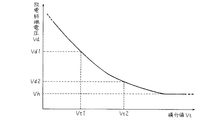
次に、放電終端電圧Vdを図2により求める。ここで、図2において、横軸は期間tsを、縦軸は放電終端電圧Vdを示す。放電終端電圧Vdを決定するにあたり、車両非使用時に蓄電部23の電圧Vcを非劣化電圧Vhより小さくするためには、期間tsが短い時は図11の太実線の特性となるようにするために放電終端電圧VdをVdmaxのように大きくし、期間tsが長い時は図12の太点線の特性となるようにするために放電終端電圧VdをVdminのように小さくする。従って、図2に示すように、放電終端電圧Vdは期間tsが長いほど小さく、短いほど大きくなるように決定すればよいことになる。なお、本実施の形態1における非劣化電圧Vhとは、車両非使用時において、キャパシタに必要な寿命(例えば10年)が確保できる蓄電部23の印加電圧と定義する。具体的には非劣化電圧Vhを6Vとした。すなわち、車両非使用時に蓄電部23の電圧Vcが6V程度であれば、キャパシタを6直列としたので、キャパシタ1個あたりの印加電圧は約1Vとなる。従って、キャパシタの劣化がほとんど進行せず、車両寿命である10年間に亘り蓄電装置11を使用できる。
Next, the discharge termination voltage Vd is obtained from FIG. Here, in FIG. 2, the horizontal axis represents the period ts, and the vertical axis represents the discharge termination voltage Vd. In determining the discharge termination voltage Vd, in order to make the voltage Vc of the
ここで、放電終端電圧Vdが非劣化電圧Vhよりも小さくなると、蓄電部23はさらに自己放電を起こすので、図12の太実線に示すように蓄電部23の電圧Vcが非劣化電圧Vhを大きく下回り、次回の起動時に蓄電部23を満充電する時間がかかってしまう。これを回避するために、図2に示すように、放電終端電圧Vdの下限値は非劣化電圧Vhとした。従って、期間tsがどれだけ長くても放電終端電圧Vdは非劣化電圧Vh未満にならないようにしている。
Here, when the discharge termination voltage Vd becomes smaller than the non-degraded voltage Vh, the
以上のことから、基本的には図2の相関関係特性をあらかじめ求めて制御回路37に内蔵したメモリに記憶しておき、計測した期間tsに対応する放電終端電圧Vdを図2の特性に従って決定すればよい。
From the above, basically, the correlation characteristics of FIG. 2 are obtained in advance and stored in a memory built in the
しかし、図2の相関関係は前記した内部抵抗値R、容量値C、および温度Tによって変化する。すなわち、図2の相関関係は内部抵抗値Rが大きいほど、容量値Cが小さいほど、温度Tが高いほど、図2の上方にシフトする。そこで、内部抵抗値R、容量値C、および温度Tが、それぞれどのような値であるかの組み合わせ毎に、図2に示すような相関関係をあらかじめ複数求めて、それを例えば最小二乗法による近似関数式として制御回路37のメモリに記憶しておく。
However, the correlation in FIG. 2 varies depending on the internal resistance value R, the capacitance value C, and the temperature T described above. That is, the correlation in FIG. 2 shifts upward in FIG. 2 as the internal resistance value R is larger, the capacitance value C is smaller, and the temperature T is higher. Therefore, a plurality of correlations as shown in FIG. 2 are obtained in advance for each combination of the values of the internal resistance value R, the capacitance value C, and the temperature T, for example, by the least square method. The approximate function formula is stored in the memory of the
なお、放電の開始時、および終了時に、電圧幅ΔVの電圧変化が発生するが、この電圧幅ΔVは、上記したように内部抵抗値Rと放電電流の積で決まる。ここで、放電回路27による放電電流は一定になるように制御されているので、キャパシタの劣化や温度Tによる内部抵抗値Rの変化に応じた電圧幅ΔVをあらかじめ求めておき、それも含めて相関関係が決定されている。 Note that a voltage change of the voltage width ΔV occurs at the start and end of discharge, and this voltage width ΔV is determined by the product of the internal resistance value R and the discharge current as described above. Here, since the discharge current by the discharge circuit 27 is controlled to be constant, the voltage width ΔV corresponding to the deterioration of the capacitor and the change of the internal resistance value R due to the temperature T is obtained in advance and is included. Correlation has been determined.
また、キャパシタの特性として温度Tが低いほど劣化進行が遅くなるため、その分、非劣化電圧Vhは大きくてもよい。従って、温度Tによる非劣化電圧Vhの変動を補正するように相関関係を求めておいてもよい。 Further, as the characteristics of the capacitor, the lower the temperature T, the slower the progress of the deterioration. Therefore, the non-deteriorating voltage Vh may be increased accordingly. Therefore, the correlation may be obtained so as to correct the fluctuation of the non-deteriorated voltage Vh due to the temperature T.
以上のことから、内部抵抗値R、容量値C、および温度Tが求まっているので、その組み合わせに応じてメモリに記憶した近似関数式を選択し、前記近似関数式に期間tsを代入することによって放電終端電圧Vdを決定することができる。従って、内部抵抗値R、容量値C、および温度Tを補正した高精度な放電終端電圧Vdの決定が可能となる。なお、例えば蓄電装置11を車室内に設置して蓄電部23の周囲温度が比較的安定している場合は、温度Tによる補正を行わないようにしてもよい。従って、必ずしも内部抵抗値R、容量値C、および温度Tの3つのパラメータで補正をしなければならないということはない。
From the above, since the internal resistance value R, the capacitance value C, and the temperature T are obtained, an approximate function equation stored in the memory is selected according to the combination, and the period ts is substituted into the approximate function equation. Thus, the discharge termination voltage Vd can be determined. Therefore, it is possible to determine the discharge termination voltage Vd with high accuracy by correcting the internal resistance value R, the capacitance value C, and the temperature T. For example, when the
このようにして、放電終端電圧Vdを求めることができるが、ここでは代表例として、図2に基き、期間tsが短かった時(ts1とする)の放電終端電圧をVd1、長かった時(ts2とする)の放電終端電圧をVd2として決定した場合の、車両使用終了後における蓄電部23の電圧Vcの経時変化を図3によりそれぞれ説明する。
In this way, the discharge termination voltage Vd can be obtained. Here, as a representative example, based on FIG. 2, the discharge termination voltage when the period ts is short (referred to as ts1) is Vd1, and when the discharge termination voltage is long (ts2). 3), the change with time of the voltage Vc of the
図3において、時刻t0からt2については、従来の図11、図12と同じであるので、詳細な説明を省略するが、ここで期間ts1は時刻t1からt2の間に、期間ts2は時刻t0からt2の間に、それぞれ相当する。 In FIG. 3, the time t0 to t2 are the same as those in FIGS. 11 and 12 in the related art, and thus detailed description thereof is omitted. Here, the period ts1 is between the times t1 and t2, and the period ts2 is the time t0. To t2.
まず、期間ts1の場合、すなわち図3の太実線の場合について説明する。期間ts1はts2に比べ短い状態であるので、蓄電部23の充電深度が浅く、自己放電が速い状態である。従って、放電終端電圧Vd1は高く設定される。これにより、車両使用が終了して制御回路37が放電回路27により蓄電部23の強制放電を開始した時刻t2から、電圧検出回路25で検出した蓄電部23の電圧Vcが放電終端電圧Vd1に達する時刻t3までの期間は短くなる。なお、時刻t2で放電が開始された直後は、従来と同様に電圧幅ΔVだけ電圧Vcが低下している。時刻t3で制御回路37は放電回路27に強制放電を停止するよう放電制御信号Dcntを送信する。これにより、電圧幅ΔVだけ電圧Vcが上昇する。時刻t3以降は図3に示すように、蓄電部23の電圧Vcが自己放電により経時的に低下し、やがて非劣化電圧Vhを下回る。このような挙動となるようにあらかじめ放電終端電圧Vd1を決定しているので、車両非使用時に蓄電部23の劣化進行が低減され、かつ不必要な放電を抑制した状態を維持することができ、長寿命化と高速起動を両立することが可能となる。
First, the case of the period ts1, that is, the case of the thick solid line in FIG. 3 will be described. Since the period ts1 is shorter than ts2, the charging depth of the
次に、期間ts2の場合、すなわち図3の太点線の場合について説明する。期間ts2はts1に比べ長い状態であるので、蓄電部23の充電深度が深く、自己放電が遅い状態である。従って、放電終端電圧Vd2は低く設定される。これにより、車両使用が終了して制御回路37が放電回路27により蓄電部23の強制放電を開始した時刻t2から、電圧検出回路25で検出した蓄電部23の電圧Vcが放電終端電圧Vd2に達する時刻t4までの期間は長くなる。なお、時刻t2で電圧幅ΔVだけ電圧Vcが低下するのは、蓄電部電圧印加時間がts1の場合と同じである。時刻t4で制御回路37は放電回路27に強制放電を停止し、その結果、電圧幅ΔVだけ電圧Vcが上昇する。時刻t4以降は図3に示すように、蓄電部23の電圧Vcが自己放電により経時的に低下し、やがて非劣化電圧Vhを下回る。ここで、図3における太実線と太点線を比較すると、蓄電部23の電圧Vcは、ほぼ同等の挙動となることがわかる。このような挙動となるようにあらかじめ放電終端電圧Vd2を決定しているので、期間ts1の場合と同様に、車両非使用時に蓄電部23の劣化進行が低減され、かつ不必要な放電を抑制した状態を維持することができ、長寿命化と高速起動を両立することが可能となる。
Next, the case of the period ts2, that is, the case of the thick dotted line in FIG. 3 will be described. Since the period ts2 is longer than ts1, the charging depth of the
以上の構成、動作により、使用終了後に、期間tsに応じて放電終端電圧Vdを決定し、その放電終端電圧Vdまで強制放電するようにしたので、期間tsがどのような値であっても、非使用時に蓄電部23の劣化進行が低減され、かつ不必要な放電を抑制した状態を維持することができる。これにより、長寿命化と高速起動を両立することが可能な蓄電装置を実現できる。
With the above configuration and operation, the discharge termination voltage Vd is determined according to the period ts after the end of use, and the discharge termination voltage Vd is forcibly discharged. Therefore, no matter what the period ts is, When not in use, the progress of deterioration of
なお、本実施の形態1では、車両の起動時と使用終了時で温度Tがほぼ一定の場合について説明したが、車両の使用時間が長期にわたると、必ずしも起動時と使用終了時の温度Tが一定であるとは限らない。すなわち、例えば冬季に車両を起動すると、その時の温度Tは低く、車両使用終了時は車両が温まっているため、温度Tが高いという場合が想定される。この際は、車両起動時に求めた蓄電部23の内部抵抗値Rと容量値Cが温度特性を有するので、車両使用終了時にこれらの値を用いて放電終端電圧Vdを求めると、その精度が悪化し、自己放電時の蓄電部23の電圧Vcが非劣化電圧Vhから離れてしまう可能性がある。
In the first embodiment, the case where the temperature T is substantially constant at the start and end of use of the vehicle has been described. However, if the use time of the vehicle is long, the temperature T at the start and end of use is not necessarily high. It is not always constant. That is, for example, when the vehicle is started in winter, the temperature T at that time is low, and the vehicle is warmed at the end of use of the vehicle. In this case, since the internal resistance value R and the capacitance value C of the
そこで、車両使用終了時の内部抵抗値と容量値(それぞれRe、Ceと呼ぶ)を得るために、車両起動時に求めた蓄電部23の内部抵抗値と容量値(それぞれRs、Csと呼ぶ)を温度補正する必要がある。そこで、以下に内部抵抗値Reと容量値Ceの温度補正方法の一例を説明する。
Therefore, in order to obtain the internal resistance value and capacity value (respectively referred to as Re and Ce) at the end of use of the vehicle, the internal resistance value and capacity value (respectively referred to as Rs and Cs) of the
まず、内部抵抗値Reの温度補正について図4を参照しながら述べる。なお、図4において、横軸は温度Tを、縦軸は内部抵抗値Rをそれぞれ示す。一般に内部抵抗値Rは温度Tに応じて大きくなる特性を有する。また、図4には複数の温度T対内部抵抗値Rの特性線が記載されているが、これは新品時から劣化が進行するに従って、前記特性線が図4の上方にシフトするためである。ゆえに、あらかじめ劣化進行度合いに応じて温度T対内部抵抗値Rの特性線を求めておき、制御回路37のメモリに記憶しておく。
First, temperature correction of the internal resistance value Re will be described with reference to FIG. In FIG. 4, the horizontal axis indicates the temperature T, and the vertical axis indicates the internal resistance value R. In general, the internal resistance value R has a characteristic of increasing with the temperature T. FIG. 4 shows a plurality of characteristic lines of temperature T vs. internal resistance value R. This is because the characteristic lines shift upward in FIG. . Therefore, a characteristic line of temperature T vs. internal resistance value R is obtained in advance according to the degree of progress of deterioration and stored in the memory of the
今、車両起動時が低温であり、使用終了時が高温であった場合を考える。起動時において、温度Tsでの内部抵抗値Rsが前記したように蓄電部23の充電時に求められる。なお、温度Tsは温度センサ35により検出される。こうして得られた温度Tsと内部抵抗値Rsから、図4において座標(Ts、Rs)に最も近い特性線を選択する。図4の場合は、下から2番目の特性線(太線)が選択されることになる。なお、この時点で座標(Ts、Rs)が図4の一番上の特性線、すなわち劣化限界特性線に達すると、蓄電部23が劣化したと判断する。
Now, consider a case where the vehicle starts at a low temperature and the end of use is a high temperature. At the time of startup, the internal resistance value Rs at the temperature Ts is obtained when the
次に、前記したように車両の使用が終了した時の温度Tを温度センサ35で測定しているので、その温度T(=Te)における起動時に選択した特性線(太線)上の内部抵抗値Reを図4より求める。この内部抵抗値Reが温度補正を行った後の値となる。
Next, since the temperature T when the use of the vehicle ends is measured by the
次に、容量値Ceの温度補正について図5を参照しながら述べる。なお、図5において、横軸は温度Tを、縦軸は容量値Cをそれぞれ示す。一般に容量値Cは温度Tに応じて小さくなる特性を有する。また、図5には複数の温度T対容量値Cの特性線が記載されているが、これは新品時から劣化が進行するに従って、前記特性線が図5の下方にシフトするためである。ゆえに、あらかじめ劣化進行度合いに応じて温度T対容量値Cの特性線を求めておき、制御回路37のメモリに記憶しておく。
Next, temperature correction of the capacitance value Ce will be described with reference to FIG. In FIG. 5, the horizontal axis represents the temperature T, and the vertical axis represents the capacitance value C. In general, the capacitance value C has a characteristic of decreasing with the temperature T. Further, FIG. 5 shows a plurality of characteristic lines of temperature T versus capacitance value C because the characteristic lines shift downward in FIG. 5 as the deterioration progresses from the time of a new product. Therefore, a characteristic line of temperature T vs. capacity value C is obtained in advance according to the degree of progress of deterioration and stored in the memory of the
ここで、内部抵抗値Rの時と同様に、車両起動時が低温であり、使用終了時が高温であった場合を考える。起動時において、温度Tsでの容量値Csが前記したように蓄電部23の充電時に求められる。なお、温度Tsは温度センサ35により検出される。こうして得られた温度Tsと容量値Csから、図5において座標(Ts、Cs)に最も近い特性線を選択する。図5の場合は、上から2番目の特性線(太線)が選択されることになる。なお、この時点で座標(Ts、Cs)が図5の一番下の特性線、すなわち劣化限界特性線に達すると、蓄電部23が劣化したと判断する。
Here, as in the case of the internal resistance value R, a case is considered where the temperature at the start of the vehicle is low and the temperature at the end of use is high. At the time of startup, the capacity value Cs at the temperature Ts is obtained when the
次に、前記したように車両の使用が終了した時の温度Tを温度センサ35で測定しているので、その温度T(=Te)における起動時に選択した特性線(太線)上の容量値Ceを図5より求める。この容量値Ceが温度補正を行った後の値となる。
Next, since the temperature T when the use of the vehicle is ended is measured by the
次に、内部抵抗値Re、容量値Ce、および温度Teの値の組み合わせ毎に、あらかじめ求めておいた複数の図2の特性の内、上記より求めた内部抵抗値Re、容量値Ce、および温度Teに対応する特性を選択する。そして、その特性により期間tsにおける放電終端電圧Vdを決定する。その結果、車両使用中に温度が変化しても、最終的には温度補正を行った放電終端電圧Vdを決定することができ、高精度化が図れる。 Next, for each combination of the values of the internal resistance value Re, the capacitance value Ce, and the temperature Te, the internal resistance value Re, the capacitance value Ce, and A characteristic corresponding to the temperature Te is selected. The discharge termination voltage Vd in the period ts is determined based on the characteristics. As a result, even if the temperature changes during use of the vehicle, it is possible to finally determine the discharge termination voltage Vd that has been subjected to temperature correction, and high accuracy can be achieved.
また、他の高精度化の方法として、内部抵抗値Rと容量値Cを蓄電部23の起動充電時に求めるのではなく、使用終了後の強制放電時に求めるようにしてもよい。この際の内部抵抗値R、容量値Cの求め方は充電時と同様に、前者は放電を中断して電圧変化幅を検出し、後者は放電による電圧変化の傾きを検出し、これらを基に計算すればよい。これにより、内部抵抗値R、容量値Cの温度補正が不要となり、制御が簡単になる。
In addition, as another high accuracy method, the internal resistance value R and the capacitance value C may be obtained at the time of forced discharge after the end of use, instead of being obtained at the time of start-up charging of the
但し、この方法では内部抵抗値Rと容量値Cを求める前に放電終端電圧Vdを決定することができないので、蓄電部23の放電開始後すぐに内部抵抗値Rと容量値Cを求め、放電終端電圧Vdを決定する必要がある。この際、蓄電部23の構成や状態により、放電終端電圧Vdが既定電圧Vmと極めて近い場合が存在すると、放電終端電圧Vdを決定する前に蓄電部23の電圧Vcが本来設定すべき放電終端電圧Vdを下回ってしまう可能性がある。従って、このような場合は、蓄電部23の充電時に内部抵抗値Rと容量値Cを求める方が望ましい。
However, in this method, since the discharge termination voltage Vd cannot be determined before the internal resistance value R and the capacitance value C are obtained, the internal resistance value R and the capacitance value C are obtained immediately after the start of the discharge of the
また、本実施の形態1では、蓄電部23の充電時に、電圧検出回路25により検出された蓄電部23の電圧Vcが既定電圧Vmに至った時刻を使用開始時として、それ以降の期間tsを計測しているが、これは、例えば車両を使用するためにイグニションスイッチ(図示せず)をオンにした時を使用開始時として期間tsの計測を行ってもよい。これにより、使用開始時を決定するために電圧検出回路25を用いる必要がなくなり、制御が簡単になる。但し、上記のように期間tsを計測すると、蓄電部23を満充電にするまでの期間も含めて計測することになる。ここで、蓄電部23は上記したように、劣化とともに内部抵抗値が大きくなり、容量値が小さくなるので、満充電までの期間が短くなる。従って、その分の誤差が期間tsに含まれるため、精度の観点からは蓄電部23の電圧Vcが既定電圧Vmに至った時刻を使用開始時とする方が望ましい。
In the first embodiment, when the
また、本実施の形態1における蓄電装置11において、蓄電部23、放電回路27、および制御回路37以外の構成要素は、蓄電装置11の外部に設けるようにしてもよい。その結果、例えば充電回路19と電圧検出回路25を蓄電装置11の外部に設けることで、蓄電部23への充電を、主電源15により行うだけでなく、車両の運転状況や主電源15の状態等に応じて、オルタネータに切り替えたり組み合わせて行うことにより、高効率化が図れる。また、主電源電圧検出回路21を蓄電装置11の外部に設けることで、車両側制御回路が主電源電圧検出回路21を共用することができる。その結果、主電源15の電圧Vbに応じて、主電源15の充電制御等を行うこともできる。
In
(実施の形態2)
図6は、本発明の実施の形態2における蓄電装置の蓄電部に印加される電圧の積分値Vtに対する放電終端電圧Vdの相関図である。図7は、本発明の実施の形態2における蓄電装置の蓄電部の電圧Vcにおける経時変化図である。
(Embodiment 2)
FIG. 6 is a correlation diagram of discharge termination voltage Vd with respect to integrated value Vt of the voltage applied to the power storage unit of the power storage device in Embodiment 2 of the present invention. FIG. 7 is a time-dependent change figure in the voltage Vc of the electrical storage part of the electrical storage apparatus in Embodiment 2 of this invention.
本実施の形態2における蓄電装置11の構成は、実施の形態1における図1と同じであるので、詳細な説明を省略する。本実施の形態2の特徴は、放電終端電圧Vdの決定動作であるので、その部分を中心に動作を説明する。
Since the configuration of
制御回路37は、蓄電装置11の使用が開始されると、その時の蓄電部23の電圧Vcを電圧検出回路25で検出する。その後、蓄電装置11の使用が終了するまでの期間tsに亘って、蓄電部23の電圧Vcを検出し続け、その積分値Vtを求める。ここで、積分値Vtは既定間隔(例えば1秒)毎に蓄電部23の電圧Vcを検出し、加算していくことで近似的に求めている。
When the use of
なお、蓄電装置11の使用開始時は、実施の形態1と同様に蓄電部23の充電が完了した時点とし、また、使用終了時は、車両側制御回路より車両の使用終了信号を受信した時点としている。
The start of use of
ここで、本実施の形態2では期間tsにおける蓄電部23の電圧Vcの積分値Vtを求めているが、蓄電装置11を車両制動システムの電源バックアップユニットとして適用した場合、通常は期間tsの間、蓄電部23の電圧Vcは既定電圧Vm(=13.2V)で一定となるので、積分値Vtは蓄電部23のエネルギーに比例した値となる。また、車両使用中に蓄電部23の電圧Vcが変動した場合も、積分値Vtは前記変動を含む蓄電部23のエネルギー相当の値となる。
Here, in the second embodiment, the integrated value Vt of the voltage Vc of the
このようにして積分値Vtを求める場合、使用開始時は、蓄電部23の充電が完了した時点とする必要がある。この理由は次の通りである。仮に、使用開始時を、車両のイグニションスイッチがオンになり、制御回路37が起動した時点とする。蓄電部23は上記したように、劣化とともに内部抵抗値Rが大きくなり、容量値Cが小さくなる傾向にある。従って、蓄電部23を定電流充電すると、蓄電部23が劣化していなければ満充電まで時間がかかり、劣化していれば早く満充電に至る。この間を積分してしまうと、劣化している蓄電部23の方が早く満充電になり、その後、既定電圧Vmを維持するので、積分値Vtが大きくなってしまう。積分値Vtと放電終端電圧Vdの関係は後述する図6に示すように、逆比例の関係であるので、劣化している蓄電部23ほど放電終端電圧Vdが低くなることになる。その結果、蓄電部23を放電回路27により放電する際に、放電しすぎる可能性がある。従って、蓄電部23を満充電にする際にも積分値Vtを求めると、放電終端電圧Vdの誤差が大きくなる場合があるので、使用開始時は、蓄電部23の充電が完了した時点としている。
Thus, when calculating | requiring the integral value Vt, it is necessary to set it as the time of the charge of the
本実施の形態2では、上記のようにして求めた積分値Vtに応じて、車両の使用終了後に、図6の相関関係から放電終端電圧Vdを決定している。図6において、横軸は積分値Vtを、縦軸は放電終端電圧Vdを、それぞれ示す。なお、積分値Vtと放電終端電圧Vdの相関関係は、実施の形態1と同様に、あらかじめ求めておき、制御回路37に記憶されている。
In the second embodiment, the discharge termination voltage Vd is determined from the correlation of FIG. 6 after the use of the vehicle is finished, according to the integrated value Vt obtained as described above. In FIG. 6, the horizontal axis represents the integrated value Vt, and the vertical axis represents the discharge termination voltage Vd. The correlation between the integrated value Vt and the discharge termination voltage Vd is obtained in advance and stored in the
ここで、積分値Vtは、図6に示すように、積分値Vtが大きいほど小さくなるように決定される。これは、次の理由による。積分値Vtが大きい場合は、期間tsに亘って、蓄電部23に多くのエネルギーが蓄えられていたことに相当するので、充電深度が深くなる。ゆえに、使用終了後に蓄電部23を放電しても、電圧の低下速度が遅くなる。従って、積分値Vtが大きいほど放電終端電圧Vdを小さくすることで、自己放電特性を近づけることができる。その結果、図6に示す積分値Vtと放電終端電圧Vdの相関関係は、図2の期間tsと放電終端電圧Vdの相関関係と同じ傾向となる。これにより、例えば積分値Vtが小さい値Vt1であれば、図6より、放電終端電圧Vdは大きい値Vd1となる。同様に、積分値Vtが大きい値Vt2であれば、放電終端電圧Vdは小さい値Vd2となる。なお、放電終端電圧Vdの下限値は非劣化電圧Vhとしているが、これは実施の形態1と同様に過放電を防止するためである。
Here, as shown in FIG. 6, the integral value Vt is determined so as to decrease as the integral value Vt increases. This is due to the following reason. When the integrated value Vt is large, it corresponds to the fact that a large amount of energy is stored in the
制御回路37は、車両使用終了時に積分値Vtから図6の相関関係を用いて放電終端電圧Vdを決定すれば、その放電終端電圧Vdまで蓄電部23を放電するように放電回路27を制御する。この時の蓄電部23の電圧Vcの経時変化を図7に示す。なお、図7の横軸は時刻tを、縦軸は蓄電部23の電圧Vcを、それぞれ示す。図7において、積分値Vtが小さい値Vt1であった場合、放電終端電圧Vdは大きい値Vd1となるので、太実線に示すように、放電開始(時刻t2)から蓄電部23の電圧VcがVd1に至る時刻t3まで放電回路27により放電し、その後は自己放電する。一方、積分値Vtが大きい値Vt2であった場合、放電終端電圧Vdは小さい値Vd2となるので、太点線に示すように、放電開始(時刻t2)から蓄電部23の電圧VcがVd2に至る時刻t4まで放電回路27により放電し、その後は自己放電する。これらの結果、図7は実施の形態1の図3と同様の結果となり、自己放電特性を非劣化電圧Vhに近づけることができる。
When the
以上の構成、動作により、使用終了後に、積分値Vtに応じて放電終端電圧Vdを決定し、その放電終端電圧Vdまで強制放電するようにしたので、期間tsの間に蓄電部23の電圧Vcが変動しても、より正確な放電終端電圧Vdにより蓄電部23の長寿命化と蓄電装置11の高速起動を両立することが可能な蓄電装置を実現できる。
With the above configuration and operation, after the end of use, the discharge termination voltage Vd is determined according to the integral value Vt and forcibly discharged to the discharge termination voltage Vd. Therefore, the voltage Vc of the
なお、本実施の形態2においても、実施の形態1と同様に、蓄電部23の温度T、内部抵抗値R、容量値Cにより放電終端電圧Vdを補正してもよい。
In the second embodiment, the discharge termination voltage Vd may be corrected by the temperature T, the internal resistance value R, and the capacitance value C of the
(実施の形態3)
図8は、本発明の実施の形態3における蓄電装置の蓄電部の電圧Vcにおける経時変化図である。図9は、本発明の実施の形態3における蓄電装置の使用終了時の電圧変化率Vkに対する放電終端電圧Vdの相関図である。
(Embodiment 3)
FIG. 8 is a time-dependent change figure in the voltage Vc of the electrical storage part of the electrical storage apparatus in Embodiment 3 of this invention. FIG. 9 is a correlation diagram of discharge termination voltage Vd with respect to voltage change rate Vk at the end of use of the power storage device according to Embodiment 3 of the present invention.
本実施の形態3における蓄電装置11の構成は、実施の形態1における図1と同じであるので、詳細な説明を省略する。本実施の形態3の特徴は、放電終端電圧Vdの決定動作であるので、その部分を中心に動作を説明する。
Since the configuration of
本実施の形態3では、制御回路37は期間tsや積分値Vtの計測を行わない。従って、使用開始時は単に蓄電部23を満充電にする動作を行う。なお、この時に実施の形態1で述べた方法により、蓄電部23の内部抵抗値Rや容量値Cを求めてもよい。
In the third embodiment, the
次に、使用終了時の動作を図8により説明する。なお、図8の横軸は時刻tを、縦軸は蓄電部23の電圧Vcを、それぞれ示す。
Next, the operation at the end of use will be described with reference to FIG. In FIG. 8, the horizontal axis represents time t, and the vertical axis represents the voltage Vc of the
図8において、時刻t10は車両の使用中である。従って、蓄電部23の電圧Vcは既定電圧Vmを維持している。
In FIG. 8, at time t10, the vehicle is in use. Therefore, the voltage Vc of the
その後、時刻t11で車両の使用を終了し、イグニションスイッチをオフにする。この時、制御回路37は蓄電部23の電圧Vcを電圧検出回路25により検出するとともに、充電回路19の動作を停止する。これにより、使用終了後は、図8の時刻t11から時刻t12に示すように、蓄電部23は既定電圧Vmから自己放電を始め、電圧Vcが経時的に低下する。その後、制御回路37は、あらかじめ記憶された電圧変化率測定期間tkが経過した時刻t12において、再び蓄電部23の電圧Vcを検出する。この時、蓄電部23の充電深度が浅ければ、図8の太実線に示すように、電圧の低下は大きくなる。この場合の時刻t12における電圧をVc2とする。一方、充電深度が深ければ、図8の太点線に示すように、電圧の低下は小さくなる。この場合の時刻t12における電圧をVc1とする。
Thereafter, use of the vehicle is terminated at time t11, and the ignition switch is turned off. At this time, the
次に、制御回路37は電圧変化率Vkを計算する。具体的には、図8の太実線の場合は、Vk=|Vm−Vc2|/tkにより、図8の太点線の場合は、Vk=|Vm−Vc1|/tkにより、それぞれ求める。このように、電圧変化率Vkは符号の付かない絶対値として求められる。以後、この電圧変化率Vkの絶対値を、単に電圧変化率Vkと呼ぶ。なお、図8の太実線における電圧変化率をVk2、図8の太点線における電圧変化率をVk1とする。
Next, the
ここまでの動作で、制御回路37は使用終了後に電圧検出回路25で検出した蓄電部23の電圧Vcを2点検出することにより、蓄電部23の単位時間当たりの電圧変化率Vkを求めている。なお、電圧変化率Vkを求めるために、さらに多数(3点以上)の電圧Vcを検出するようにしてもよい。多数点の電圧Vcを求めた場合は、電圧変化率Vkも複数得られるので、例えばそれらを平均することで、より高精度な電圧変化率Vkを求めることができる。
In the operation so far, the
時刻t12で電圧変化率Vkを求めた後、制御回路37は図9により放電終端電圧Vdを決定する。ここで、図9の横軸は電圧変化率Vkを、縦軸は放電終端電圧Vdを、それぞれ示す。上記したように、充電深度が深いほど電圧変化率Vkは小さくなるので、放電終端電圧Vdは小さくなる。従って、図9に示すように、放電終端電圧Vdは電圧変化率Vkが大きいほど大きくなるように決定される。この相関関係は、あらかじめ求められて制御回路37に記憶されている。なお、放電終端電圧Vdの下限値は、実施の形態1、2と同様に非劣化電圧Vhとしている。
After obtaining the voltage change rate Vk at time t12, the
ここで、具体例を説明する。上記した電圧変化率Vk1については、電圧変化率Vk2より小さいので、図9により、電圧変化率Vk1に対する放電終端電圧Vd1は小さくなる。一方、電圧変化率Vk2は大きいので、その放電終端電圧Vd2は大きくなる。 Here, a specific example will be described. Since the voltage change rate Vk1 described above is smaller than the voltage change rate Vk2, the discharge termination voltage Vd1 with respect to the voltage change rate Vk1 is reduced according to FIG. On the other hand, since the voltage change rate Vk2 is large, the discharge termination voltage Vd2 becomes large.
次に、制御回路37は図8の時刻t12にて、上記のようにして求められた放電終端電圧Vd1、Vd2まで蓄電部23を放電するように放電回路27を制御する。その結果、電圧変化率が大きい場合(=Vk2)は、図8の太実線に示すように、蓄電部23の電圧Vcが放電終端電圧Vd2に至る時刻t13まで、蓄電部23を放電し、その後、放電回路27を停止する。これにより、以後、蓄電部23は自己放電を行う。また、電圧変化率が小さい場合(=Vk1)は、図8の太点線に示すように、蓄電部23の電圧Vcが放電終端電圧Vd1に至る時刻t14まで、蓄電部23を放電し、その後、放電回路27を停止する。これにより、以後、蓄電部23は自己放電を行う。このような動作により、電圧変化率Vkの大小に応じて放電終端電圧Vdを決定しているので、時刻t14以降の自己放電特性を非劣化電圧Vhに近づけることができる。なお、放電回路27の動作開始時や終了時には蓄電部23の電圧Vcが電圧幅ΔVだけ変動しているが、これは実施の形態1で述べた通り、内部抵抗値Rにより発生している。
Next, at time t12 in FIG. 8, the
以上の構成、動作により、使用終了後に、電圧変化率Vkに応じて放電終端電圧Vdを決定し、その放電終端電圧Vdまで強制放電するようにしたので、蓄電部23の使用中における電圧Vcの変動に影響されず、より正確な放電終端電圧Vdが決定できる。その結果、蓄電部23の長寿命化と蓄電装置11の高速起動を両立することが可能な蓄電装置を実現できる。
With the above configuration and operation, after termination of use, the discharge termination voltage Vd is determined according to the voltage change rate Vk, and forced discharge is performed up to the discharge termination voltage Vd. A more accurate discharge termination voltage Vd can be determined without being affected by fluctuations. As a result, it is possible to realize a power storage device that can achieve both a long life of the
なお、本実施の形態3においても、実施の形態1と同様に、蓄電部23の温度T、内部抵抗値R、容量値Cにより放電終端電圧Vdを補正してもよい。
In the third embodiment, the discharge termination voltage Vd may be corrected by the temperature T, the internal resistance value R, and the capacitance value C of the
また、実施の形態1〜3では、蓄電部23の電圧Vcに基いて放電終端電圧Vdまでの放電制御を行っているが、これは各キャパシタ毎に電圧Vcn(nはキャパシタの番号)を検出して、各キャパシタ毎に決定した放電終端電圧Vdn(nはキャパシタの番号)まで放電制御を行うようにしてもよい。この場合、各キャパシタに放電回路を設ける構成となるが、前記放電回路としてバランス回路を用いる構成とすれば、各キャパシタの電圧バランスを取ることができる上に、放電終端電圧Vdnまでの放電制御も可能となり、回路構成の効率化を図ることができる。なお、放電終端電圧Vdnまで放電すれば、後は各キャパシタの自己放電を行わせるために、前記バランス回路を各キャパシタから切り離す構成とすることが望ましい。これにより、各キャパシタの過放電を低減することができる。
In the first to third embodiments, the discharge control up to the discharge termination voltage Vd is performed based on the voltage Vc of the
また、実施の形態1〜3において、蓄電部23には蓄電素子として電気二重層キャパシタを用いたが、これは電気化学キャパシタ等の他のキャパシタでもよい。なお、電気化学キャパシタを用いる場合は、過放電により劣化が進行するので、非劣化電圧Vhを過放電電圧以上に設定することにより、蓄電部23の寿命を延ばすことができる。
In the first to third embodiments, the electric double layer capacitor is used as the electric storage element in the
また、実施の形態1〜3において、蓄電装置11を車両制動システムの電子制御部に対する電源バックアップシステムに用いた場合について説明したが、それに限らず、アイドリングストップ、ハイブリッド、電動パワーステアリング、電動ターボ等の各種システムにおける補助電源等として用いてもよい。
Further, in the first to third embodiments, the case where the
本発明にかかる蓄電装置は、蓄電部の長寿命化と高速起動を両立することができるので、特に蓄電部に電力を蓄え、必要な時に放電する車両用の蓄電装置等として有用である。 Since the power storage device according to the present invention can achieve both a long life and high-speed startup of the power storage unit, it is particularly useful as a power storage device for vehicles that stores power in the power storage unit and discharges it when necessary.
11 蓄電装置
19 充電回路
23 蓄電部
25 電圧検出回路
27 放電回路
35 温度センサ
37 制御回路
DESCRIPTION OF
Claims (7)
前記蓄電部の電圧(Vc)を検出する電圧検出回路と、
前記蓄電部を強制放電する放電回路と、
前記電圧検出回路と前記放電回路に接続される制御回路と、を備え、
前記制御回路は、前記蓄電部の電圧(Vc)を放電終端電圧(Vd)まで前記強制放電させた後、前記蓄電部を自己放電させるものであり、前記蓄電部の前記自己放電による前記蓄電部の電圧(Vc)の低下が速い状態となるほど前記放電終端電圧(Vd)を大きくするように制御する蓄電装置。 A power storage unit comprising a capacitor;
A voltage detection circuit for detecting a voltage (Vc) of the power storage unit;
A discharge circuit for forcibly discharging the power storage unit;
A control circuit connected to the voltage detection circuit and the discharge circuit,
The control circuit is configured to self-discharge the power storage unit after forcibly discharging the power storage unit voltage (Vc) to a discharge termination voltage (Vd), and the power storage unit by the self-discharge of the power storage unit The power storage device that controls the discharge termination voltage (Vd) to increase as the voltage (Vc) decreases more rapidly .
前記制御回路は、前記期間(ts)における前記蓄電部の電圧(Vc)の積分値(Vt)を求め、自己放電特性を変化させる前記パラメータを前記積分値(Vt)とする請求項2に記載の蓄電装置。 The control circuit includes a timer that measures a period (ts) at the start and end of use,
The said control circuit calculates | requires the integral value (Vt) of the voltage (Vc) of the said electrical storage part in the said period (ts), The said parameter which changes a self-discharge characteristic is made into the said integral value (Vt). Power storage device.
Priority Applications (1)
| Application Number | Priority Date | Filing Date | Title |
|---|---|---|---|
| JP2008320440A JP5195388B2 (en) | 2008-12-17 | 2008-12-17 | Power storage device |
Applications Claiming Priority (1)
| Application Number | Priority Date | Filing Date | Title |
|---|---|---|---|
| JP2008320440A JP5195388B2 (en) | 2008-12-17 | 2008-12-17 | Power storage device |
Publications (3)
| Publication Number | Publication Date |
|---|---|
| JP2010145143A JP2010145143A (en) | 2010-07-01 |
| JP2010145143A5 JP2010145143A5 (en) | 2012-01-26 |
| JP5195388B2 true JP5195388B2 (en) | 2013-05-08 |
Family
ID=42565745
Family Applications (1)
| Application Number | Title | Priority Date | Filing Date |
|---|---|---|---|
| JP2008320440A Active JP5195388B2 (en) | 2008-12-17 | 2008-12-17 | Power storage device |
Country Status (1)
| Country | Link |
|---|---|
| JP (1) | JP5195388B2 (en) |
Families Citing this family (2)
| Publication number | Priority date | Publication date | Assignee | Title |
|---|---|---|---|---|
| EP3708436B1 (en) * | 2017-11-10 | 2022-01-05 | Panasonic Intellectual Property Management Co., Ltd. | Vehicle-mounted power source device |
| US11183844B2 (en) | 2018-06-14 | 2021-11-23 | Arm Limited | Supplying energy to an apparatus |
Family Cites Families (3)
| Publication number | Priority date | Publication date | Assignee | Title |
|---|---|---|---|---|
| JP4385664B2 (en) * | 2003-07-08 | 2009-12-16 | パナソニック株式会社 | Vehicle power supply |
| JP4807058B2 (en) * | 2005-11-10 | 2011-11-02 | パナソニック株式会社 | Vehicle power supply |
| JP5055984B2 (en) * | 2006-12-01 | 2012-10-24 | パナソニック株式会社 | Power storage device |
-
2008
- 2008-12-17 JP JP2008320440A patent/JP5195388B2/en active Active
Also Published As
| Publication number | Publication date |
|---|---|
| JP2010145143A (en) | 2010-07-01 |
Similar Documents
| Publication | Publication Date | Title |
|---|---|---|
| JP4807058B2 (en) | Vehicle power supply | |
| JP4873106B2 (en) | Power supply | |
| JP6508094B2 (en) | Vehicle power system | |
| JP4001072B2 (en) | Vehicle power generation system | |
| JP4513791B2 (en) | Power storage device | |
| US11046264B2 (en) | Vehicle-mounted emergency power supply device | |
| JP2013176197A (en) | Power supply device | |
| WO2013027337A1 (en) | Vehicle power source device | |
| JP5026362B2 (en) | Automatic stop and start device for internal combustion engine | |
| JP2009092628A (en) | Electric storage device | |
| JP4710547B2 (en) | Vehicle power supply | |
| JP2007261433A (en) | Battery control device and battery control method | |
| JP5024054B2 (en) | Power storage device | |
| JP5195388B2 (en) | Power storage device | |
| JP2009146843A (en) | Power storage device | |
| JP2008172908A (en) | Vehicular power supply unit | |
| JP5012483B2 (en) | Power storage device | |
| JP2010188851A (en) | Power source device for vehicle | |
| JP2009095209A (en) | Power storage apparatus | |
| JP2010190707A (en) | Energy storage device | |
| JP4735523B2 (en) | Power storage device | |
| JP2013179801A (en) | Power supply device | |
| JP5277819B2 (en) | Power storage device | |
| JP5024053B2 (en) | Power storage device | |
| JP2009092627A (en) | Electric storage device |
Legal Events
| Date | Code | Title | Description |
|---|---|---|---|
| A521 | Written amendment |
Free format text: JAPANESE INTERMEDIATE CODE: A523 Effective date: 20111201 |
|
| A621 | Written request for application examination |
Free format text: JAPANESE INTERMEDIATE CODE: A621 Effective date: 20111201 |
|
| RD01 | Notification of change of attorney |
Free format text: JAPANESE INTERMEDIATE CODE: A7421 Effective date: 20120112 |
|
| A977 | Report on retrieval |
Free format text: JAPANESE INTERMEDIATE CODE: A971007 Effective date: 20121005 |
|
| A131 | Notification of reasons for refusal |
Free format text: JAPANESE INTERMEDIATE CODE: A131 Effective date: 20121016 |
|
| A521 | Written amendment |
Free format text: JAPANESE INTERMEDIATE CODE: A523 Effective date: 20121206 |
|
| A521 | Written amendment |
Free format text: JAPANESE INTERMEDIATE CODE: A523 Effective date: 20121210 |
|
| RD01 | Notification of change of attorney |
Free format text: JAPANESE INTERMEDIATE CODE: A7421 Effective date: 20121214 |
|
| TRDD | Decision of grant or rejection written | ||
| A01 | Written decision to grant a patent or to grant a registration (utility model) |
Free format text: JAPANESE INTERMEDIATE CODE: A01 Effective date: 20130108 |
|
| A61 | First payment of annual fees (during grant procedure) |
Free format text: JAPANESE INTERMEDIATE CODE: A61 Effective date: 20130121 |
|
| FPAY | Renewal fee payment (event date is renewal date of database) |
Free format text: PAYMENT UNTIL: 20160215 Year of fee payment: 3 |
|
| R151 | Written notification of patent or utility model registration |
Ref document number: 5195388 Country of ref document: JP Free format text: JAPANESE INTERMEDIATE CODE: R151 |
|
| FPAY | Renewal fee payment (event date is renewal date of database) |
Free format text: PAYMENT UNTIL: 20160215 Year of fee payment: 3 |