JP5193768B2 - Pneumatic tire - Google Patents
Pneumatic tire Download PDFInfo
- Publication number
- JP5193768B2 JP5193768B2 JP2008240945A JP2008240945A JP5193768B2 JP 5193768 B2 JP5193768 B2 JP 5193768B2 JP 2008240945 A JP2008240945 A JP 2008240945A JP 2008240945 A JP2008240945 A JP 2008240945A JP 5193768 B2 JP5193768 B2 JP 5193768B2
- Authority
- JP
- Japan
- Prior art keywords
- block
- blocks
- sipes
- tread
- block group
- Prior art date
- Legal status (The legal status is an assumption and is not a legal conclusion. Google has not performed a legal analysis and makes no representation as to the accuracy of the status listed.)
- Expired - Fee Related
Links
Images


Description
この発明は、トレッド部に、溝により区画してなるブロックを備える空気入りタイヤに関し、より具体的には、氷上性能の飛躍的な向上をもたらす技術を提案するものである。 The present invention relates to a pneumatic tire provided with a block formed by a groove in a tread portion, and more specifically, proposes a technique that brings about a dramatic improvement in performance on ice.
空気入りタイヤでは、従来より、エッジ効果を高めることによって、ウェット路面、氷上路面等に対する駆動、制動及び旋回性能を高めることを目的に、主溝や横溝をもってブロックを区画形成するとともに、形成されたブロック内にサイプを付加することが広く一般に行われている(例えば、特許文献1)。
しかしながら、上記従来の空気入りタイヤでは、より高い駆動、制動及び旋回性能の要求の下で、ブロック内に多数のサイプを配設するため、また特に氷上性能を大きな接地面積の確保によって向上させるために、ブロック一つ一つの大きさを比較的大きく形成していたことから、タイヤの負荷転動時にブロックを均一に接地させることが困難であった。また、ブロック一つ一つの大きさが大きいことから、ブロックの中央域において水膜を効率良く除去することができなかった。さらに、サイプを多数設けたことにより、サイプによって区画された分割ブロック部分の剛性が低くなり過ぎて、接地時に分割ブロック部分の倒れ込みが生じて接地性が悪化するという問題があった。このように、ブロックに多数のサイプを設けることでエッジ効果を向上させることが可能となるものの、サイプの配設によって接地性等が低下するという新たな弊害が生じることになるため、サイプの配設による氷上性能等の向上には一定の限界があった。 However, in the conventional pneumatic tire described above, a large number of sipes are arranged in the block under the demand for higher driving, braking and turning performance, and in particular, the performance on ice is improved by securing a large ground contact area. In addition, since the size of each block is relatively large, it is difficult to uniformly ground the block during load rolling of the tire. Further, since the size of each block is large, the water film cannot be efficiently removed in the central area of the block. Further, since a large number of sipes are provided, the rigidity of the divided block portions partitioned by the sipes becomes too low, and there is a problem that the divided block portions fall down at the time of grounding and the grounding property is deteriorated. As described above, although it is possible to improve the edge effect by providing a large number of sipes in the block, a new adverse effect that the grounding property and the like deteriorate due to the arrangement of the sipes will occur. There was a certain limit to the improvement in performance on ice.
それゆえ、この発明は、これらの問題点を解決することを課題とするものであり、その目的は、トレッドパターンの適正化を図ることにより氷上性能を飛躍的に向上させることにある。 Therefore, an object of the present invention is to solve these problems, and an object of the present invention is to dramatically improve the performance on ice by optimizing the tread pattern.
前記の目的を達成するため、この発明の空気入りタイヤは、溝により区画した、複数の独立したブロックを互いに密集させてなるブロック群を、トレッド部の少なくとも一部に設け、該ブロック群におけるブロックの基準ピッチ長さをP(mm)、該ブロック群の幅をW(mm)、該基準ピッチ長さPと該幅Wとで区画される、該ブロック群の基準区域内に存在する前記ブロックの個数をa(個)、該基準区域内のネガティブ率をN(%)としたとき、a/(P×W×(1−N/100))で与えられる、該ブロック群の単位実接地面積当りのブロック個数密度Sを0.003個/mm2以上0.02個/mm2以下の範囲内とし、かつ、各ブロック群の複数個のブロックにサイプをそれぞれ設けたことを特徴とする空気入りタイヤである。 In order to achieve the above object, the pneumatic tire according to the present invention is provided with a block group formed by concentrating a plurality of independent blocks partitioned by a groove in at least a part of the tread portion, and the blocks in the block group The block existing in the reference area of the block group defined by the reference pitch length P (mm), the width of the block group W (mm), and the reference pitch length P and the width W. A / (P × W × (1−N / 100) ), where a is a (number) and the negative rate in the reference area is N (%). The block number density S per area is in the range of 0.003 / mm 2 or more and 0.02 / mm 2 or less, and sipes are respectively provided in a plurality of blocks in each block group. It is a pneumatic tire.
なお、ここでいう「ブロックの基準ピッチ長さ」とは、ブロック群を構成する1つのブロック列におけるブロックの繰り返し模様の最小単位を指すものとし、例えば1つのブロックとそのブロックを区画する溝によってパターンの繰り返し模様が規定されている場合は、ブロック1個分のトレッド周方向長さとこのブロックのトレッド周方向に隣接する溝1つ分のトレッド周方向長さとを加算したものをブロックの基準ピッチ長さとする。 The “reference pitch length of the block” here refers to the minimum unit of the repeated pattern of the block in one block row constituting the block group. For example, one block and a groove partitioning the block are used. If the pattern repeat pattern is specified, the block's reference pitch is the sum of the tread circumferential length of one block and the tread circumferential length of one adjacent groove in the tread circumferential direction of this block. Length.
また、「ブロック群の幅W」とは、ブロックを密集配置してなるブロック群のトレッド幅方向長さを指し、例えばブロック群がトレッド全体に存在する場合は、トレッド接地幅を指すものとする。 Further, the “block group width W” refers to the length in the tread width direction of the block group formed by densely arranging the blocks. For example, when the block group is present in the entire tread, it indicates the tread ground contact width. .
さらに、ブロック群の「実接地面積」とは、ブロック群の基準区域内に在る全ブロックの総表面積をいうものとし、言い換えれば、基準ピッチ長さPと幅Wとの積で規定される、上記基準区域の面積から個々のブロックを区画している溝の面積を減算した面積を指すものである。 Furthermore, the “actual ground contact area” of the block group means the total surface area of all the blocks in the reference area of the block group, in other words, is defined by the product of the reference pitch length P and the width W. The area obtained by subtracting the area of the grooves defining the individual blocks from the area of the reference area.
さらに、「サイプ」とは、トレッド表面からタイヤ内部に切り込まれた薄い切り込みであって、接地時に閉じることが可能なものを指す。 Furthermore, “sipe” refers to a thin notch cut into the tire from the tread surface, which can be closed when touched.
この発明の空気入りタイヤにあっては、ブロック群において十分な溝面積を確保しつつ、ブロックを密集配置する構成を採用したことから、各ブロック群のそれぞれのブロックのトータルエッジ長さ及び各方向のエッジ成分長さを大きく増加させることができ、このため、ブロックに多数のサイプを配設するまでもなく、言い換えればブロック剛性を大きく低下させることなく優れたエッジ効果を発揮させることができる。また、ブロック一つあたりの接地面積を小さくし、ブロック一つ一つの接地性を向上させたことから、高い氷上性能等を発揮させることができる。しかも、それぞれのブロックを小さくすることで、ブロックの中央域からブロック周縁までの距離を小さくすることができるので、ブロックによる水膜の除去効果を向上させることができる。よって、小さいブロックを密集配置しただけでもブロックエッジの効果及び接地性向上の効果等により高い氷上性能を得ることができるが、この発明ではさらに、このようなブロックにサイプを適正配置することによって一層効果的に氷上性能を高め、他性能とのバランスを保つことが可能となる。すなわち、同じエッジ効果を狙うにあたりブロックを密集配置させただけの場合よりもサイプを設けた場合の方がブロック個数密度Sを小さく設定できるので、ブロックの剛性を必要とする他性能との両立を図り得る。 In the pneumatic tire of the present invention, since the configuration in which the blocks are densely arranged while securing a sufficient groove area in the block group is adopted, the total edge length and each direction of each block of each block group The edge component length of the block can be greatly increased. Therefore, it is not necessary to arrange a large number of sipes in the block, in other words, an excellent edge effect can be exhibited without greatly reducing the block rigidity. In addition, since the ground contact area per block is reduced and the ground contact performance of each block is improved, high performance on ice can be exhibited. In addition, by reducing the size of each block, the distance from the central area of the block to the periphery of the block can be reduced, so that the water film removal effect by the block can be improved. Therefore, even if small blocks are densely arranged, high performance on ice can be obtained due to the effect of the block edge and the effect of improving the ground contact property. However, in the present invention, it is further possible to further arrange the sipes in such blocks. It is possible to effectively improve the performance on ice and maintain a balance with other performances. In other words, the block number density S can be set smaller in the case where sipes are provided than in the case where blocks are densely arranged to aim at the same edge effect, so that compatibility with other performances requiring block rigidity can be achieved. It can be planned.
従って、この発明の空気入りタイヤによれば、優れた接地性及びエッジ効果の確保と、ブロックによる効率的な水膜の除去とを実現することにより氷上性能を飛躍的に向上させることができる。 Therefore, according to the pneumatic tire of the present invention, it is possible to dramatically improve the performance on ice by ensuring excellent grounding property and edge effect and efficiently removing the water film by the block.
なお、この発明の空気入りタイヤにて、他性能との調整により各ブロック群のブロックを比較的大きくすることが要求される場合には、ブロック個数密度Sを0.003個/mm2以上0.01個/mm2以下の範囲内とし、各ブロック群の同一ブロック内に設けるサイプの本数を2本以上とすることが好ましい。この場合、同一ブロックに設けられた2本以上のサイプを相互に平行に配置することがより好ましい。 In the pneumatic tire of the present invention, when the size of each block group is required to be relatively large by adjusting with other performances, the block number density S is 0.003 / mm 2 or more and 0. The number of sipes provided in the same block of each block group is preferably 2 or more within a range of 0.01 pieces / mm 2 or less. In this case, it is more preferable to arrange two or more sipes provided in the same block in parallel to each other.
又は、この発明の空気入りタイヤにて、他性能との調整により各ブロック群のブロックを比較的小さくすることが要求される場合には、ブロック個数密度Sを0.005個/mm2以上0.02個/mm2以下の範囲内とし、各ブロック群の同一ブロックにそれぞれ設けるサイプの本数を1本とすることが好ましい。 Or, in the pneumatic tire of the present invention, when it is required to make the blocks of each block group relatively small by adjusting with other performances, the block number density S is 0.005 / mm 2 or more and 0. It is preferable that the number of sipes provided in the same block of each block group is one in the range of 0.02 pieces / mm 2 or less.
しかも、この発明の空気入りタイヤにあっては、サイプの、トレッド踏面における延在方向を2種類以上の異なる向きに設定することが好ましい。 Moreover, in the pneumatic tire of the present invention, it is preferable to set the extending direction of the sipe on the tread surface in two or more different directions.
この発明の空気入りタイヤによれば、優れた接地性及びエッジ効果の確保と、ブロックによる効率的な水膜の除去とを実現することにより氷上性能を飛躍的に向上させることができる。 According to the pneumatic tire of the present invention, it is possible to dramatically improve the performance on ice by ensuring excellent grounding performance and edge effect and efficiently removing the water film by the block.
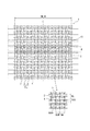
以下、この発明の実施の形態を図面に基づいて説明する。ここに、図1は、この発明に従う一実施形態の空気入りタイヤ(以下「タイヤ」という)のトレッドパターンを示した部分展開図である。 Hereinafter, embodiments of the present invention will be described with reference to the drawings. FIG. 1 is a partial development view showing a tread pattern of a pneumatic tire (hereinafter referred to as “tire”) according to an embodiment of the present invention.
この実施形態のタイヤは、図示を省略するが、左右一対のビードコア間でトロイド状に延びるカーカスと、このカーカスのクラウン部のタイヤ径方向外側に配置したベルトと、このベルトのタイヤ径方向外側に配置したトレッド部とを具える慣例に従ったタイヤ構造を有し、トレッド部に図1に示したトレッドパターンを有するものである。 Although the tire of this embodiment is not illustrated, a carcass extending in a toroidal shape between a pair of left and right bead cores, a belt disposed on the outer side in the tire radial direction of the crown portion of the carcass, and an outer side in the tire radial direction of the belt It has a tire structure in accordance with the conventional practice including a tread portion arranged, and has the tread pattern shown in FIG. 1 in the tread portion.
このタイヤは、トレッド部1に、溝2により区画した、独立した複数のブロック3を互いに密集させてなるブロック群GBを有する。ブロック群GBは、トレッド部1の全体に存在する。ここでは、各ブロック3の表面輪郭形状を八角形としており、それぞれのブロック3をトレッド周方向に千鳥状に配置している。そしてこのタイヤは、ブロック群GBにおけるブロック3の基準ピッチ長さをP(mm)、該ブロック群GBの幅をW(mm)(この実施形態では、トレッド部1の全体にブロック3が配置されているので、トレッド接地幅TWと等しい。)、該基準ピッチ長さPと該幅Wとで区画される、該ブロック群GBの基準区域Z(図中斜線で示す領域)内に存在するブロック3の個数をa(個)、基準区域Z内のネガティブ率をN(%)としたとき、
![]()
![]()
さらに、このタイヤでは、ブロック群GBの全ブロック3にトレッド幅方向に延びるサイプ4が各2本設けられている。サイプ4は、接地時のブロック3の過大な変形を抑制してさらなる氷上性能の向上を図る観点からその中間部分がトレッド周方向に向けてジグザグ状に屈折しながらトレッド幅方向に延在するものとしているが、サイプ4の形態は、図示例に限らず直線状とすることができ、あるいはタイヤ径方向に向けて屈折する、いわゆる3次元サイプとすることもできる。また、図示例では、サイプ4は、その両端にてブロック3を区画する溝2に開口しているが、これに限らず一方の端又は両端をブロック3内で終端させてなる、いわゆる盲サイプとすることもできる。これによれば、ブロック3の剛性の低下を抑制することができ、これは特にブロック3内に複数のサイプ4を設けた場合に有利である。また、この発明では、サイプ4は全てのブロック3に設ける必要はなく、複数個のブロック3に設ければ所定の効果を得ることができる。より高いエッジ効果等が必要とされる場合には各ブロック群のほぼ半数以上のブロック3にサイプ4を設けることが好ましい。
Moreover, in this tire,
ところで、ブロック群GBにおけるネガティブ率Nは5%〜50%とすることが好ましい。ブロック群GBにおけるネガティブ率Nが5%未満の場合は、排水性が不十分となる他、ブロック一つ一つの大きさが大きくなり過ぎて所要のエッジ効果の実現が難しくなり、一方、50%を超えると接地面積が小さくなり過ぎて、操縦安定性が低下するおそれがあるからである。また、ブロック群GBにおけるブロック3の個数密度Sが0.003(個/mm2)未満の場合は、多数のサイプの形成なしには(ブロック剛性の大きな低下を伴う)、高いエッジ効果の実現が難しくなり、また、ブロックあたりの接地面積が大きくなり過ぎブロックを均一に接地させることが困難なる。一方、ブロック3の個数密度Sが0.02(個/mm2)を超えるとブロック3が小さくなり過ぎてサイプを配置するには所要のブロック剛性の実現が難しくなる。
Meanwhile, negative ratio N of the block group G B is preferably 5% to 50%. If negative ratio N of the block group G B is less than 5%, except that drainage is insufficient, the realization of desired edge effect becomes too large the size of each one block is difficult, whereas, 50 This is because if it exceeds 50%, the contact area becomes too small, and the steering stability may be lowered. Also, if the number density S of the
この実施形態のタイヤにあっては、ブロック群GBにおいて十分な溝面積を確保しつつ、ブロック3を密集配置する構成を採用したことから、それぞれのブロック3のトータルエッジ長さ及びエッジ方向(異なる方向に向いたエッジの数)を大きく増加させることができ、このため、各ブロック群GBのブロック3に多数のサイプ4を配設するまでもなく、言い換えればブロック剛性を大きく低下させることなく優れたエッジ効果を発揮させることができる。なお、ドライ路面上での操縦安定性等は、ブロック3を密集させることで確保される。また、ブロック一つあたりの接地面積を小さくし、ブロック一つ一つの接地性を向上させたことから、高い氷上性能等を発揮させることができる。しかも、それぞれのブロック3を小さくすることで、ブロック3の中央域からブロック周縁までの距離を小さくすることができるので、ブロック3による水膜の除去効果を向上させることができる。よって、小さいブロック3を密集配置しただけでもブロックエッジの効果及び接地性向上の効果等により高い氷上性能を得ることができるが、この発明ではさらに、このようなブロック3にサイプを適正配置することによって一層効果的に氷上性能を高めるとともに他性能とのバランスを保つことも可能となる。すなわち、同じエッジ効果を狙うにあたりブロックを密集配置させただけの場合よりもサイプを設けた場合の方がブロック個数密度Sを小さく設定できるので、ブロック剛性を必要とする他性能との両立を図り得る。
In the tire of this embodiment, while ensuring a sufficient groove area in block group G B, since employing the configuration in which densely arranged
従って、この実施形態のタイヤによれば、優れた接地性及びエッジ効果の確保と、ブロック3による効率的な水膜の除去とを実現することにより、氷上路面等における制動、駆動及び旋回性能を顕著に向上させることができる。なお、ブロック群GBにおけるブロック3の個数密度Sを、0.003〜0.015個/mm2の範囲内とすれば、エッジ効果とブロック剛性とのより良好なバランスが得られ、より効果的に氷上性能を向上させることができる。さらに、このようにブロック3を千鳥状に配置することにより、ブロック3の密集配置を容易に実現することができる。
Therefore, according to the tire of this embodiment, it is possible to achieve braking, driving and turning performance on the road surface on ice, etc. by ensuring excellent grounding performance and edge effect and efficiently removing the water film by the
また、この実施形態のタイヤによれば、各ブロック3をトレッド周方向に千鳥状に配置したことから、タイヤ転動時に、より多くのブロック3の形成下で、それぞれのエッジを逐次作用させて一層優れたエッジ効果を発揮させることができる。また、トレッド幅方向に隣接するブロック3の相互間で路面への接地タイミングをずらすことができるので、パターンノイズを低減させることもできる。
Further, according to the tire of this embodiment, since the
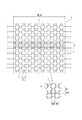
なお、各ブロックに対するサイプ4の配設本数は2本に限らず、ブロック剛性と必要とされるエッジ長さ(エッジ効果)との調整により、例えば、図2及び3に示す、この発明の他の実施形態のタイヤのように、ブロック個数密度Sに応じて(つまりブロック3の大きさに応じて)3本としたり1本としたりすることができる。より具体的には、例えば操縦安定性や耐摩耗性等の他性能とのバランスを図る目的で、ブロック3を比較的大きく形成することが要求される場合には、図2のように、ブロック個数密度Sを0.003個/mm2以上0.01個/mm2以下の範囲内とし、ブロックにそれぞれ設けるサイプの本数を2本以上とすることが好ましい。このようにすれば、他性能とのバランスを図りつつ所要のエッジ効果を得ることができる。そして、このようにブロック3に複数のサイプを配設した場合、同一ブロック内でのサイプは相互に平行に配置することが好ましい。このように同一ブロック内でのサイプを平行に配置することで、サイプ間の分割ブロック部分の形態を均一にしてブロック剛性の部分的な強弱を無くすことができ、氷上性能をさらに向上させることができるからである。また、ブロック剛性の部分的な強弱を無くすことは、耐偏摩耗性にも有利である。なお、より高いブロック剛性の要求の下では、ブロック個数密度Sを0.003個/mm2以上0.008個/mm2以下とすることがより好ましい。
The number of
一方、例えば操縦安定性や耐摩耗性等の他性能とのバランスを図る目的で、ブロック3を比較的小さく形成することが要求される場合には、図3のように、ブロック個数密度Sを0.005個/mm2以上0.02個/mm2以下の範囲内とし、ブロック3にそれぞれ設けるサイプの本数を1本とすることが好ましい。このようにすれば、他性能とのバランスを図りつつ所要のエッジ効果を得ることができる。なお、より高いエッジ効果の要求の下では、ブロック個数密度Sを0.007個/mm2以上0.015個/mm2以下とすることより好ましい。
On the other hand, when it is required to make the
また、図1〜3に示す実施形態では、サイプの延在方向を、全て同一方向に設定しているが、サイプの方向は、重視する性能に合わせて設定することができる。例えば、トラクションやブレーキ性能を重視する場合には、トレッド幅方向に沿って設定することができ、一方で横方向の入力(コーナリング性能)を重視する場合には、トレッド幅方向に対して傾斜させて設定することができる。また、トレッド内でブロック単位で部分的にサイプの方向を異ならせることで、より効果的に性能調整することができる。図4に示す実施形態のタイヤでは、サイプの延在方向は、トレッド幅方向の中央域Ain及び最外側域Aoutでトレッド幅方向に設定し、該中央域Ainに隣接する第1中間域Am1でトレッド幅方向に対して45度の傾斜をもって設定し、該第1中間域Am1と該最外側域Aoutとの間の第2中間域Am2ではトレッド幅方向に直交する方向(トレッド周方向)に設定している。このようにすれば、トラクション性能、ブレーキ性能及びコーナリング性能の良好なバランスを図りつつこれらを効率的に向上させることができる。 In the embodiment shown in FIGS. 1 to 3, the sipe extending directions are all set to the same direction, but the sipe direction can be set according to the performance to be emphasized. For example, when importance is attached to traction and braking performance, it can be set along the tread width direction. On the other hand, when importance is attached to lateral input (cornering performance), it is inclined with respect to the tread width direction. Can be set. Moreover, performance can be adjusted more effectively by partially changing the sipe direction in units of blocks in the tread. In the tire of the embodiment shown in FIG. 4, the extending direction of the sipe is set in the tread width direction at the center area A in and the outermost area A out in the tread width direction, and is adjacent to the center area A in. In the area A m1 , set with an inclination of 45 degrees with respect to the tread width direction, and in the second intermediate area A m2 between the first intermediate area A m1 and the outermost area A out , the direction orthogonal to the tread width direction (Tread circumferential direction) is set. If it does in this way, these can be improved efficiently, aiming at the good balance of traction performance, brake performance, and cornering performance.
次に、この発明に従う実施例1及び2のタイヤ、従来技術に従う従来例1のタイヤ及び比較例1〜3のタイヤをそれぞれ試作し、氷上性能及び静粛性についての性能評価を行ったので、以下説明する。 Next, since the tires of Examples 1 and 2 according to the present invention, the tire of Conventional Example 1 according to the prior art and the tires of Comparative Examples 1 to 3 were respectively prototyped and performance evaluations on ice performance and quietness were performed, explain.
実施例1及び2のタイヤは、図1及び4に示すトレッドパターンをトレッド部に有する、205/55R16サイズの乗用車用ラジアルタイヤである。これらのタイヤは、トレッド部全体に、溝により区画形成した、独立した複数のブロックを密集させてなるブロック群GBを有する。各ブロックの表面輪郭形状は、正八角形であり、そのトレッド周方向長さBL(mm)、トレッド幅方向長さBW(mm)、高さ(溝底からの高さ)BH(mm)、トレッド周方向に隣接するブロック間距離BGL(mm)、トレッド幅方向に隣接するブロック間距離BGW(mm)、及び、トレッド周方向に対して斜め方向に隣接するブロック間距離BGO(mm)を表1に示す。また各タイヤにおける、ブロックの基準ピッチ長さP(mm)、ブロック群GBの幅W(mm)、ブロックの基準ピッチ長さPとブロック群の幅Wとで区画される、ブロック群GBの基準区域Zにおけるネガティブ率N(%)、該基準区域Z内に存在するブロックの個数a(個)、ブロック群GBの単位実接地面積当りのブロック個数密度S(個/mm2)、ブロック群GBにおける、トレッド幅方向に数えたブロック列数(列)を表1に示す。さらに、実施例1及び2のタイヤでは、各ブロックに2本のサイプを設けており、その諸元を表1に併せて示す。なお、実施例2のタイヤでは、タイヤ赤道面Cを跨いだ中央域Ain(トレッド幅TWの19.4%)及び各最外域Aout(トレッド幅TWの10.5%)にてサイプの、トレッド幅方向に対する傾斜角度を0度とし、該中央域Ainに隣接する各第1中間域Am1(トレッド幅TWの19.4%)にて、サイプの、トレッド幅方向に対する傾斜角度を45度とし、各第1中間域Am1と各最外域Aoutとの間の各第2中間域Am2(トレッド幅TWの13.0%)にて、サイプの、トレッド幅方向に対する傾斜角度を90度としている。 The tires of Examples 1 and 2 are 205 / 55R16 size radial tires for passenger cars having the tread pattern shown in FIGS. 1 and 4 in the tread portion. These tires have the entire tread portion was partitioned and formed by a groove, a block group G B composed by densely independent multiple blocks. The surface contour of each block is a regular octagon, and its tread circumferential length BL (mm), tread width direction length BW (mm), height (height from the groove bottom) BH (mm), tread Table 1 shows the inter-block distance BGL (mm) adjacent in the circumferential direction, the inter-block distance BGW (mm) adjacent in the tread width direction, and the inter-block distance BGO (mm) adjacent in the oblique direction with respect to the tread circumferential direction. Shown in Also in each tire, the reference pitch length P of the block (mm), the width W of the block group G B (mm), is defined by the width W of the reference pitch length P and the block group of the block, the block group G B negative ratio in the reference zone Z of the N (%), the number of blocks existing in the reference zone Z a (number), number of blocks per unit actual ground contact area of the block group G B density S (pieces / mm 2), in the block group G B, the number of block rows counted in the tread width direction (column) are shown in Table 1. Furthermore, in the tires of Examples 1 and 2, two sipes are provided in each block, and the specifications are shown in Table 1. In addition, in the tire of Example 2, the sipe in the central area A in (19.4% of the tread width TW) and the outermost areas A out (10.5% of the tread width TW) straddling the tire equatorial plane C is obtained. The inclination angle with respect to the tread width direction is set to 0 degree, and the inclination angle of the sipe with respect to the tread width direction is set to each first intermediate area A m1 (19.4% of the tread width TW) adjacent to the central area A in. The inclination angle of the sipe with respect to the tread width direction in each second intermediate area A m2 (13.0% of the tread width TW) between each first intermediate area A m1 and each outermost area A out. Is 90 degrees.
比較のため、205/55R16サイズの乗用車用ラジアルタイヤであり、トレッド部全体のネガティブ率が実施例1のタイヤのネガティブ率と同じである、図8に示すトレッドパターンを有する従来例1のタイヤを併せて試作した。従来例1のタイヤは、トレッド部に、トレッド周方向に延びる4本の周方向溝と、これらに隣接するリブ状の陸部(トレッド幅方向中央から中央陸部、中間陸部、ショルダー陸部とする。)とを備える。トレッド幅方向内側に位置する2本の周方向溝は、幅が8mm、深さが8.9mmであり、トレッド幅方向外側に位置する2本の周方向溝は、幅が6mm、深さが8.9mmである。中央陸部、中間陸部及びショルダー陸部には、トレッド周方向に傾斜して延びる横溝によってブロックが多数区画形成されており、各ブロックにはジグザグ状に延びるサイプが多数形成されている。サイプの本数は、1ピッチあたり65本である。その他の諸元を表1に示す。 For comparison, a 205 / 55R16 size radial tire for passenger cars, the tire of Conventional Example 1 having the tread pattern shown in FIG. 8 in which the negative rate of the entire tread portion is the same as the negative rate of the tire of Example 1. A prototype was also made. The tire of Conventional Example 1 has four circumferential grooves extending in the tread circumferential direction and rib-shaped land portions adjacent to these in the tread portion (from the center in the tread width direction to the central land portion, intermediate land portion, shoulder land portion). And). The two circumferential grooves located on the inner side in the tread width direction have a width of 8 mm and a depth of 8.9 mm, and the two circumferential grooves located on the outer side in the tread width direction have a width of 6 mm and a depth of It is 8.9 mm. In the central land portion, the intermediate land portion, and the shoulder land portion, a large number of blocks are formed by lateral grooves extending inclining in the tread circumferential direction, and a large number of sipes extending in a zigzag shape are formed in each block. The number of sipes is 65 per pitch. Other specifications are shown in Table 1.
さらに比較のため、205/55R16サイズの乗用車用ラジアルタイヤであり、トレッド部に図5〜7に示すトレッドパターンを有する比較例1〜3のタイヤについても併せて試作した。比較例1のタイヤは、ブロックにサイプを設けていないことを除いては、実施例1及び2のタイヤと同じであり、比較例2及び3のタイヤは、ブロックに1本又は複数本のサイプを設けているものの、ブロック個数密度Sが、0.003〜0.02個/mm2の範囲外のものである。各比較例のタイヤの諸元を表1に示す。 Further, for comparison, tires of Comparative Examples 1 to 3 which are 205 / 55R16 size radial tires for passenger cars and have a tread pattern shown in FIGS. The tire of Comparative Example 1 is the same as the tires of Examples 1 and 2 except that the blocks are not provided with sipes, and the tires of Comparative Examples 2 and 3 have one or more sipes in the block. However, the block number density S is outside the range of 0.003 to 0.02 block / mm 2 . Table 1 shows the specifications of the tires of the comparative examples.

(性能評価)
上記各供試タイヤについて、サイズ6.5J×16のリムに組み付け、内圧220kPa(相対圧)のとして車両に装着し、以下の試験を行って性能を評価した。
(Performance evaluation)
About each said test tire, it assembled | attached to the rim of size 6.5Jx16, and it mounted | worn with the vehicle as internal pressure 220kPa (relative pressure), and performed the following tests and evaluated the performance.
(1)氷上での制動性能評価試験
氷上での制動性能は、氷板路面上を時速20km/hからフル制動したときの制動距離を測定し、その測定した距離から評価した。その評価結果を表2に示す。表2中の評価は、従来例1の結果を100とし実施例1及び2のタイヤ及び比較例1〜3のタイヤについて指数で表したものであり、数値が大きいほど氷上での制動性能が良好であることを示す。
(1) Brake performance evaluation test on ice The braking performance on ice was evaluated from the measured distance by measuring the braking distance when full braking was performed from 20 km / h on an ice plate road surface. The evaluation results are shown in Table 2. The evaluation in Table 2 is the index of the tires of Examples 1 and 2 and the tires of Comparative Examples 1 to 3 with the result of Conventional Example 1 being 100, and the larger the value, the better the braking performance on ice. Indicates that
(2)氷上での駆動性能評価試験
氷上での駆動性能は、氷上路面上をフル加速し、20mの距離に達するまでの時間を測定し、その測定した時間から評価した。その評価結果を表2に示す。表2中の評価は、従来例1の結果を100とし実施例1及び2のタイヤ及び比較例1〜3のタイヤについて指数で表したものであり、数値が大きいほど氷上上での駆動性能が良好であることを示す。
(2) Driving performance evaluation test on ice The driving performance on ice was evaluated from the measured time by fully accelerating the road surface on ice and measuring the time required to reach a distance of 20 m. The evaluation results are shown in Table 2. The evaluation in Table 2 is expressed as an index for the tires of Examples 1 and 2 and the tires of Comparative Examples 1 to 3 with the result of Conventional Example 1 being 100, and the larger the value, the more the driving performance on ice. Shows good.
(3)氷上での操縦安定性評価試験
氷上での操縦安定性は、氷板路面のテストコースを各種走行モードで走行したときのテストドライバーによる制動性、加速性、直進性およびコーナリング性を総合的にフィーリング評価することによって行った。その評価結果を表2に示す。表2中の評価は、従来例1の結果を100とし実施例1及び2のタイヤ及び比較例1〜3のタイヤについて指数で表したものであり、数値が大きいほど氷上での操縦安定性が良好であることを示す。
(3) Steering stability evaluation test on ice Steering stability on ice combines braking performance, acceleration performance, straight running performance, and cornering performance by a test driver when traveling on various test modes on an ice plate road surface. This was done by evaluating the feeling. The evaluation results are shown in Table 2. The evaluation in Table 2 is the index of the tires of Examples 1 and 2 and the tires of Comparative Examples 1 to 3 with the result of Conventional Example 1 being 100. The larger the numerical value, the more the steering stability on ice. Shows good.
(4)静粛性(パターンノイズ)試験
静粛性は、ドライ状態の一般路を各種走行モードで走行したときのテストドライバーによる静粛性をフィーリング評価することによって行った。その評価結果を表2に示す。表2中の評価は、従来例1の結果を100とし実施例1及び2のタイヤ及び比較例1〜3のタイヤについて指数で表したものであり、数値が大きいほど静粛性が良好であることを示す。
(4) Quietness (Pattern Noise) Test Quietness was performed by evaluating the quietness of a test driver when driving on a dry general road in various driving modes. The evaluation results are shown in Table 2. The evaluation in Table 2 is the index of the tires of Examples 1 and 2 and the tires of Comparative Examples 1 to 3 with the result of Conventional Example 1 being 100, and the greater the numerical value, the better the silence. Indicates.
表2に示す評価結果から、実施例1及び2のタイヤ並びに比較例1のタイヤは、従来例1のタイヤに比べて、氷上制動性能、氷上駆動性能、氷上操縦安定性及び静粛性について優れた性能を示している。また、サイプを設けた実施例1及び2のタイヤはサイプを設けていない比較例1のタイヤに比べて上記各性能においてより優れた性能を示している。 From the evaluation results shown in Table 2, the tires of Examples 1 and 2 and the tire of Comparative Example 1 were superior to the tire of Conventional Example 1 in terms of braking performance on ice, driving performance on ice, driving stability on ice, and quietness. Shows performance. In addition, the tires of Examples 1 and 2 provided with sipes showed better performance in the above-mentioned performances than the tires of Comparative Example 1 not provided with sipes.
この発明によって、優れた接地性及びエッジ効果の確保と、ブロックによる効率的な水膜の除去とを実現することにより氷上性能を飛躍的に向上させることが可能となった。 According to the present invention, it is possible to dramatically improve the performance on ice by ensuring excellent grounding property and edge effect and efficiently removing the water film by the block.
1 トレッド部
2 溝
3 ブロック
4 サイプ
GB ブロック群
P ブロック群の基準ピッチ長さ
W ブロック群の幅
Z 基準区域
1 width Z reference area of the reference pitch length W blocks of the
Claims (5)
該ブロック群におけるブロックの基準ピッチ長さをP(mm)、該ブロック群の幅をW(mm)、該基準ピッチ長さPと該幅Wとで区画される、該ブロック群の基準区域内に存在する前記ブロックの個数をa(個)、該基準区域内のネガティブ率をN(%)としたとき、
a/(P×W×(1−N/100))で与えられる、該ブロック群の単位実接地面積当りのブロック個数密度Sを0.003個/mm2以上0.02個/mm2以下の範囲内とし、かつ、
各ブロック群の複数個のブロックにサイプをそれぞれ設けたことを特徴とする空気入りタイヤ。 A block group formed by concentrating a plurality of independent blocks partitioned by a groove is provided in at least a part of the tread portion,
In the reference area of the block group, the reference pitch length of the block in the block group is defined as P (mm), the width of the block group is defined as W (mm), and the reference pitch length P and the width W are defined. When the number of blocks existing in a is a (pieces) and the negative rate in the reference area is N (%),
The block number density S per unit actual contact area of the block group given by a / (P × W × (1−N / 100) ) is 0.003 / mm 2 or more and 0.02 / mm 2 or less. Within the scope of
A pneumatic tire characterized in that sipes are respectively provided in a plurality of blocks of each block group.
Priority Applications (1)
| Application Number | Priority Date | Filing Date | Title |
|---|---|---|---|
| JP2008240945A JP5193768B2 (en) | 2008-09-19 | 2008-09-19 | Pneumatic tire |
Applications Claiming Priority (1)
| Application Number | Priority Date | Filing Date | Title |
|---|---|---|---|
| JP2008240945A JP5193768B2 (en) | 2008-09-19 | 2008-09-19 | Pneumatic tire |
Publications (2)
| Publication Number | Publication Date |
|---|---|
| JP2010070105A JP2010070105A (en) | 2010-04-02 |
| JP5193768B2 true JP5193768B2 (en) | 2013-05-08 |
Family
ID=42202280
Family Applications (1)
| Application Number | Title | Priority Date | Filing Date |
|---|---|---|---|
| JP2008240945A Expired - Fee Related JP5193768B2 (en) | 2008-09-19 | 2008-09-19 | Pneumatic tire |
Country Status (1)
| Country | Link |
|---|---|
| JP (1) | JP5193768B2 (en) |
Families Citing this family (2)
| Publication number | Priority date | Publication date | Assignee | Title |
|---|---|---|---|---|
| RU2506170C1 (en) * | 2010-03-12 | 2014-02-10 | Бриджстоун Корпорейшн | Pneumatic tire |
| JP6101054B2 (en) * | 2012-11-22 | 2017-03-22 | 株式会社ブリヂストン | Pneumatic tire |
Family Cites Families (8)
| Publication number | Priority date | Publication date | Assignee | Title |
|---|---|---|---|---|
| JPS62185602U (en) * | 1986-05-19 | 1987-11-26 | ||
| JPH04331608A (en) * | 1991-01-18 | 1992-11-19 | Yokohama Rubber Co Ltd:The | Pneumatic tire |
| JP3062359B2 (en) * | 1991-10-24 | 2000-07-10 | オーツタイヤ株式会社 | Studless tires for passenger cars |
| JPH0891016A (en) * | 1994-09-21 | 1996-04-09 | Bridgestone Corp | Pneumatic tire having block pattern |
| JP3533757B2 (en) * | 1995-06-02 | 2004-05-31 | 東洋ゴム工業株式会社 | Pneumatic tire |
| JPH10244813A (en) * | 1997-03-03 | 1998-09-14 | Bridgestone Corp | Pneumatic tire |
| JP4330389B2 (en) * | 2003-07-31 | 2009-09-16 | 住友ゴム工業株式会社 | Pneumatic tire |
| JP4797457B2 (en) * | 2005-06-17 | 2011-10-19 | 横浜ゴム株式会社 | Pneumatic tire |
-
2008
- 2008-09-19 JP JP2008240945A patent/JP5193768B2/en not_active Expired - Fee Related
Also Published As
| Publication number | Publication date |
|---|---|
| JP2010070105A (en) | 2010-04-02 |
Similar Documents
| Publication | Publication Date | Title |
|---|---|---|
| JP5922688B2 (en) | Pneumatic tire | |
| JP5275903B2 (en) | Pneumatic tire | |
| WO2010137273A1 (en) | Pneumatic tire | |
| WO2010116710A1 (en) | Pneumatic tire | |
| JP5331433B2 (en) | Pneumatic tire | |
| JP2010116030A (en) | Pneumatic tire | |
| JP2010155478A (en) | Pneumatic tire | |
| EP2546076A1 (en) | Pneumatic tire | |
| JP5241422B2 (en) | Pneumatic tire | |
| JP5351905B2 (en) | Pneumatic tire | |
| JP2010095221A (en) | Pneumatic tire | |
| JP5394698B2 (en) | Pneumatic tire | |
| JP5292124B2 (en) | Pneumatic tire | |
| WO2011111331A1 (en) | Pneumatic tire | |
| JP5193768B2 (en) | Pneumatic tire | |
| JP5308858B2 (en) | Pneumatic tire | |
| JP5489515B2 (en) | Pneumatic tire | |
| JP5399718B2 (en) | Pneumatic tire | |
| JP5489523B2 (en) | Pneumatic tire | |
| JP5368786B2 (en) | Pneumatic tire | |
| JP2010105416A (en) | Pneumatic tire | |
| JP5265310B2 (en) | Pneumatic tire | |
| JP5193776B2 (en) | Pneumatic tire | |
| JP5150470B2 (en) | Pneumatic tire | |
| WO2010092743A1 (en) | Pneumatic tire |
Legal Events
| Date | Code | Title | Description |
|---|---|---|---|
| A621 | Written request for application examination |
Free format text: JAPANESE INTERMEDIATE CODE: A621 Effective date: 20110815 |
|
| A977 | Report on retrieval |
Free format text: JAPANESE INTERMEDIATE CODE: A971007 Effective date: 20120914 |
|
| A131 | Notification of reasons for refusal |
Free format text: JAPANESE INTERMEDIATE CODE: A131 Effective date: 20120925 |
|
| A521 | Written amendment |
Free format text: JAPANESE INTERMEDIATE CODE: A523 Effective date: 20121119 |
|
| TRDD | Decision of grant or rejection written | ||
| A01 | Written decision to grant a patent or to grant a registration (utility model) |
Free format text: JAPANESE INTERMEDIATE CODE: A01 Effective date: 20130108 |
|
| A61 | First payment of annual fees (during grant procedure) |
Free format text: JAPANESE INTERMEDIATE CODE: A61 Effective date: 20130204 |
|
| R150 | Certificate of patent or registration of utility model |
Ref document number: 5193768 Country of ref document: JP Free format text: JAPANESE INTERMEDIATE CODE: R150 Free format text: JAPANESE INTERMEDIATE CODE: R150 |
|
| FPAY | Renewal fee payment (event date is renewal date of database) |
Free format text: PAYMENT UNTIL: 20160208 Year of fee payment: 3 |
|
| R250 | Receipt of annual fees |
Free format text: JAPANESE INTERMEDIATE CODE: R250 |
|
| R250 | Receipt of annual fees |
Free format text: JAPANESE INTERMEDIATE CODE: R250 |
|
| R250 | Receipt of annual fees |
Free format text: JAPANESE INTERMEDIATE CODE: R250 |
|
| R250 | Receipt of annual fees |
Free format text: JAPANESE INTERMEDIATE CODE: R250 |
|
| LAPS | Cancellation because of no payment of annual fees |