JP5192201B2 - Wireless communication system and method - Google Patents
Wireless communication system and method Download PDFInfo
- Publication number
- JP5192201B2 JP5192201B2 JP2007221291A JP2007221291A JP5192201B2 JP 5192201 B2 JP5192201 B2 JP 5192201B2 JP 2007221291 A JP2007221291 A JP 2007221291A JP 2007221291 A JP2007221291 A JP 2007221291A JP 5192201 B2 JP5192201 B2 JP 5192201B2
- Authority
- JP
- Japan
- Prior art keywords
- data
- transmission path
- node
- destination
- transmission
- Prior art date
- Legal status (The legal status is an assumption and is not a legal conclusion. Google has not performed a legal analysis and makes no representation as to the accuracy of the status listed.)
- Active
Links
- 238000000034 method Methods 0.000 title claims description 70
- 238000004891 communication Methods 0.000 title claims description 58
- 230000005540 biological transmission Effects 0.000 claims description 279
- 238000012545 processing Methods 0.000 claims description 52
- 230000008569 process Effects 0.000 claims description 30
- 238000003672 processing method Methods 0.000 claims 47
- 230000003139 buffering effect Effects 0.000 claims 1
- 238000010586 diagram Methods 0.000 description 12
- 238000012546 transfer Methods 0.000 description 12
- 230000006870 function Effects 0.000 description 6
- 238000004590 computer program Methods 0.000 description 5
- 230000008859 change Effects 0.000 description 3
- 238000007781 pre-processing Methods 0.000 description 3
- 230000011664 signaling Effects 0.000 description 2
- 230000008901 benefit Effects 0.000 description 1
- 238000006243 chemical reaction Methods 0.000 description 1
- 238000013467 fragmentation Methods 0.000 description 1
- 238000006062 fragmentation reaction Methods 0.000 description 1
- 238000012986 modification Methods 0.000 description 1
- 230000004048 modification Effects 0.000 description 1
- 238000012856 packing Methods 0.000 description 1
- 238000011144 upstream manufacturing Methods 0.000 description 1
Images


Description
この出願は、2006年9月7日に出願された米国特許仮出願第60/842,675号の利益を主張するものであり、この文献については如何なる目的においても参考までに全内容を本願に取り入れる。 This application claims the benefit of US Provisional Application No. 60 / 842,675, filed September 7, 2006, the entire contents of which are hereby incorporated by reference for any purpose. Incorporate.
本発明は、包括的には無線通信システム用の方法及び機器に関し、特に、制御ノード、中間ノード及び宛先ノードを含む、無線通信システム、無線通信方法及び無線通信機器に関する。 The present invention relates generally to a method and apparatus for a wireless communication system, and more particularly to a wireless communication system, a wireless communication method, and a wireless communication apparatus including a control node, an intermediate node, and a destination node.
無線機器の数の増大と無線サービスの高まる需要の故に、無線通信システムは拡大し続けている。高まる需要を満たすために、無線プロバイダは、極めて多数の無線送信機を配置させている。しかしながら、その代わりとして、無線プロバイダは、リレーベースのシステムも利用している。 Wireless communication systems continue to expand due to the increasing number of wireless devices and the increasing demand for wireless services. In order to meet the growing demand, wireless providers have deployed a very large number of wireless transmitters. However, as an alternative, wireless providers also use relay-based systems.
リレーベースのシステムでは、無線システムの或るノードは、中継ノードと称される1つ以上の中間ノードを用いて無線システム内の別のノードと通信することができる。幾つかのシステムでは、中継ノードは、中継ステーションと称され、このようなノードの組み合わせ及び送信元ノードと宛先ノードとの間の接続を伝送路と称する。リレーベースのシステムは、如何なる種類の無線ネットワークにおいても見つけることができる。 In a relay-based system, one node of a wireless system can communicate with another node in the wireless system using one or more intermediate nodes called relay nodes. In some systems, a relay node is referred to as a relay station, and such a combination of nodes and a connection between a source node and a destination node is referred to as a transmission line. Relay-based systems can be found in any type of wireless network.
リレーベースのシステム例は、マルチホップリレー(MR)ネットワークである。図1は、米国電気電子学会(IEEE)802.16ファミリの規格に基づく従来のMRネットワーク100の一例を示す図である。
An example relay-based system is a multi-hop relay (MR) network. FIG. 1 is a diagram showing an example of a
図1に示すように、MRネットワーク100は、1つ以上の送信機、例えばベースステーション(BS)110、1つ以上の中継ステーション(RS)120(RS 120a、120b及び120cを含む)、及び1つ以上の加入者ステーション(SS)130(SS 130w、130x、130y及び130zを含む)を含むことができる。
As shown in FIG. 1,
MRネットワークでは、送信ステーション(例えばBS110)と加入者ステーション(例えば、SS 130w、SS130x、SS130y、SS130zなど)との間の通信は、1つ以上の中継ステーション(例えば、RS120a、RS120b、RS120cなど)を用いて実現することができる。例えば、MRネットワーク100では、RS120aは、BS110からデータを受信し、そのデータを別の中継ステーション(例えばRS120b)に送信することができる。或いは又、RS120aは、下位の中継ステーション(例えば、RS120b)からデータを受信して、そのデータをBS110に送信することができる。別の例として、RS120cは、RS120bからデータを受信して、そのデータをサポートされる加入者ステーション(例えば、SS130w)に送信することができる。或いは又、RS120cは、加入者ステーション(例えばSS130w)からデータを受信して、そのデータを上位の中継ステーション(例えば、RS120b)に送信することができる。
In an MR network, communication between a transmitting station (eg, BS 110) and a subscriber station (eg, SS 130w, SS 130x, SS 130y, SS 130z, etc.) is performed by one or more relay stations (eg, RS 120a, RS 120b, RS 120c, etc.). It can be realized using. For example, in the
MRネットワーク100などの幾つかの例では、スケジューリングアルゴリズムを用いることができ、スケジューリングアルゴリズムによって加入者ステーション(例えばSS130w、SS130x、SS130y、SS130zなど)は、そのネットワーク(即ち、範囲内の加入者ステーションに対してBS110を機能させることによって構成される通信ネットワーク)に対して一回のみイニシャルエントリを競争することができる。ネットワークに対するイニシャルエントリを一旦勝ち取ると、BS110によってアクセススロットが割り当てられる。他の例では、アクセススロットを、各フレーム間隔で動的割り当てすることができる。いずれの場合でも、アクセススロットは、拡張したり、又は縮小したりすることができるが、アクセススロットは特定の加入者ステーションに割り当てられたままで残ることになり、これにより、他の加入者ステーションによる当該アクセススロットの使用を排除することができる。
In some examples, such as the
図2は、周波数分割多元接続(OFDMA)を用いた、IEEE802.16ファミリの規格に基づくメディアアクセス制御(MAC)フレームフォーマットの一例を示す図である。図2に示すように、伝送時間(タイム)を可変長サブフレーム、即ち、アップリンク(UL)サブフレームとダウンリンク(DL)サブフレームに分割することができる。詳細に示してはいないが、ULサブフレームは、レンジングチャネル、チャネル品質情報チャネル(CQICH)及びデータを含むULデータバーストを含むものとできる。 FIG. 2 is a diagram illustrating an example of a media access control (MAC) frame format based on the IEEE 802.16 family of standards using frequency division multiple access (OFDMA). As shown in FIG. 2, the transmission time can be divided into variable length subframes, ie, uplink (UL) subframe and downlink (DL) subframe. Although not shown in detail, the UL subframe may include a UL data burst including a ranging channel, a channel quality information channel (CQICH) and data.
DLサブフレームは、プリアンブル、フレーム制御ヘッダ(FCH)、DL−MAP、UL−MAP及びDLデータバースト領域を含むことができる。プリアンブルは、同期のための基準を提供するのに用いることができる。例えば、プリアンブルは、タイミングオフセット、周波数オフセット及び電力を調整するのに用いることができる。FCHは、例えばSS130用のデコード情報を含む、各接続用のフレーム制御情報を含むことができる。 The DL subframe may include a preamble, a frame control header (FCH), a DL-MAP, a UL-MAP, and a DL data burst region. The preamble can be used to provide a reference for synchronization. For example, the preamble can be used to adjust timing offset, frequency offset, and power. The FCH can include frame control information for each connection including, for example, decoding information for the SS 130.
DL−MAPメッセージ及びUL−MAPメッセージは、ダウンリンク及びアップリンク通信用のそれぞれのチャネルを割り当てるのに用いることができる。即ち、DL−MAPメッセージは、アクセススロット位置のディレクトリを現在のダウンリンク・サブフレーム内に提供することができ、UL−MAPメッセージは、アクセススロット位置のディレクトリを現在のアップリンク・サブフレーム内に提供することができる。DL−MAPメッセージでは、このディレクトリは、1つ以上のDL−MAPインフォメーションエレメント(MAP IE)の形式とすることができる。DL−MAPメッセージにおける各MAP IEは、単一接続(即ち、単一のSS130との接続)用のパラメータを含むことができる。これらのパラメータは、現在のサブフレームにおいて、データバーストが位置する箇所、データバーストの長さ、データバーストの所定の受信者の識別、及び1つ以上の伝送パラメータを特定するのに用いることができる。 DL-MAP messages and UL-MAP messages can be used to allocate respective channels for downlink and uplink communications. That is, the DL-MAP message can provide the access slot location directory in the current downlink subframe, and the UL-MAP message can access the access slot location directory in the current uplink subframe. Can be provided. For DL-MAP messages, this directory may be in the form of one or more DL-MAP information elements (MAP IEs). Each MAP IE in the DL-MAP message may include parameters for a single connection (ie, a connection with a single SS 130). These parameters can be used in the current subframe to identify where the data burst is located, the length of the data burst, the identity of a given recipient of the data burst, and one or more transmission parameters. .
例えば、各MAP IEは、データバーストが向かう宛先機器(例えば、SS130w、SS130x、SS130y、SS130zなど)を識別するための接続ID(CID)、ダウンリンク伝送が規定されることになるダウンリンクインターバル使用コードを示すためのダウンリンクインターバル使用コード(DIUC)、データバーストが開始するOFDMAシンボルのオフセットを指示するOFDMAシンボルオフセット、データバーストを運ぶための最小インデックスOFDMAサブチャネルを指示するサブチャネルオフセットなどを含むことができる。また、MAP IEは、例えばブースト化パラメータ、OFDMAシンボルの番号を示すパラメータ、サブチャネルの番号を示すパラメータなどの他のパラメータを含むことができる。以下の説明に用いるように、従来からのMACヘッダ及びMAP IEは、接続切替制御データと称される。 For example, each MAP IE uses a connection ID (CID) for identifying a destination device (for example, SS130w, SS130x, SS130y, SS130z, etc.) to which a data burst is directed, and uses a downlink interval in which downlink transmission is specified. Includes downlink interval usage code (DIUC) to indicate code, OFDMA symbol offset indicating the offset of the OFDMA symbol where the data burst starts, subchannel offset indicating the minimum index OFDMA subchannel for carrying the data burst, etc. be able to. Further, the MAP IE may include other parameters such as a boosting parameter, a parameter indicating an OFDMA symbol number, and a parameter indicating a subchannel number. As used in the following description, the conventional MAC header and MAP IE are referred to as connection switching control data.
データバースト領域は、DL−MAP及びUL−MAPメッセージの各々の後に続けることができる。データバースト領域の各データバーストは、対応する接続切替制御データの制御の種類に応じて変調し、符号化することができる。例えば、図3を参照するに、MAP IE“w”は、データバースト“w”用の制御情報を提供し、MAP IE“x”は、データバースト“x”用の制御情報を提供し、MAP IE“y”は、データバースト“y”用の制御情報を提供し、MAP IE“z”は、データバースト“z”用の制御情報を提供することができる。 The data burst region can follow each of the DL-MAP and UL-MAP messages. Each data burst in the data burst area can be modulated and encoded according to the type of control of the corresponding connection switching control data. For example, referring to FIG. 3, MAP IE “w” provides control information for data burst “w”, MAP IE “x” provides control information for data burst “x”, and MAP IE “x” provides control information for data burst “x”. IE “y” may provide control information for data burst “y”, and MAP IE “z” may provide control information for data burst “z”.
再び図1を参照するに、BS110は、各々がRS120cに対する加入者デバイスである、SS130w、SS130x、SS130y及びSS130z用のデータバーストを受信することができる。BS110は、各SS130用の接続切替制御データを生成し、接続切替制御データをフレームのDL MAP IEスロットに挿入することができる。BS110は、各SS130に関連付けられたデータバーストを各接続切替制御データに対応するデータバースト領域に挿入することができる。BS110は、そのフレームを伝送路に沿った第1ノード、即ちRS120aに送信することができる。RS120aは、当該データを受信し、各接続切替制御データを処理して、どのデータがRS120aの加入者機器向けであるかを決定することができる。当該データのいずれもRS120aの加入者機器向けではない場合には、RS120aは、伝送路に沿って次のRS120に転送することができる。この例の場合では、当該データのいずれもRS120aの加入者機器に向けられるものではなく、RS120aは、当該データをRS120bに送信することができる。
Referring back to FIG. 1, BS 110 can receive data bursts for SS 130w, SS 130x, SS 130y, and SS 130z, each of which is a subscriber device to
同様に、RS120bは、当該データを受信し、各接続切替制御データを処理して、どのデータがRS120bの加入者機器向けであるかを決定することができる。当該データのいずれもRS120bの加入者機器向けではない場合には、RS120bにおいても、伝送路に沿った次のRS120、即ちRS120cに転送することができる。RS120cは、当該データを受信し、各接続切替制御データを処理して、どのデータがRS120cの加入者機器向けであるかを決定することができる。この例の場合では、SS130w、SS130x、SS130y及びSS130zは、RS120cの加入者機器であり、RS120cは、接続切替制御データを処理して、MAP IEに格納される伝送パラメータに従って、その適切なデータを各SS130に送信することができる。 Similarly, the RS 120b can receive the data and process each connection switching control data to determine which data is for the RS 120b subscriber device. If none of the data is intended for RS120b subscriber equipment, RS120b can also transfer to the next RS120 along the transmission path, that is, RS120c. The RS 120c can receive the data and process each connection switching control data to determine which data is for the RS 120c subscriber device. In this example, SS130w, SS130x, SS130y and SS130z are RS120c subscriber devices, which process the connection switching control data and send the appropriate data according to the transmission parameters stored in the MAP IE. It can transmit to each SS130.
MRネットワーク100では、伝送路に沿った各RS120は、個々の制御データ及び制御データに関連付けられたデータが宛先に到着するまで、当該フレームの全ての接続切替制御データ(例えば、MACヘッダ及びMAP IE)を処理することになる。従って、例えば、図1の接続切替制御データの各々は、当該データが宛先に到着する前に、3回処理されることになる。これは、システムリソースのかなりの使用と、対応する伝送レイテンシを生じさせることになる。
In the
本発明の一態様では、複数の中間ノードと複数の宛先機器を含む無線通信ネットワークにおける無線データを処理する方法を提供する。本方法は、複数の中間ノードの各々に対する少なくとも1つの伝送路を決定するステップを含む。少なくとも1つの伝送路は、該少なくとも1つの伝送路に沿った全ての中間ノードと関連付けられたデータを含む。また、本方法は、該少なくとも1つの伝送路の各々用の、宛先ノード識別子である伝送路識別子を決定するステップと、伝送データを該複数の宛先機器のうちの少なくとも1つの宛先機器に送信するステップを含む。伝送データは、少なくとも1つの伝送路識別子に基づいて送信される。 In one aspect of the present invention, a method for processing wireless data in a wireless communication network including a plurality of intermediate nodes and a plurality of destination devices is provided. The method includes determining at least one transmission path for each of a plurality of intermediate nodes. The at least one transmission line includes data associated with all intermediate nodes along the at least one transmission line. The method also includes determining a transmission path identifier that is a destination node identifier for each of the at least one transmission path, and transmitting transmission data to at least one destination apparatus of the plurality of destination apparatuses. Includes steps. The transmission data is transmitted based on at least one transmission path identifier.
本発明の別の態様では、複数の中間ノードと複数の宛先機器を含む無線通信ネットワークにおける無線通信用の無線通信ステーションを提供する。無線通信ステーションは、データ及び命令を格納するための少なくとも1つのメモリと、該メモリにアクセスするように構成された少なくとも1つのプロセッサとを備える。少なくとも1つのプロセッサは、命令を実行するときに、複数の中間ノードの各々に対する少なくとも1つの伝送路を決定するように構成されている。この少なくとも1つの伝送路の情報には、該少なくとも1つの伝送路に沿った全ての中間ノードと関連付けられたデータを含む。また、少なくとも1つのプロセッサは、命令を実行するときに、該少なくとも1つの伝送路の各々用の、宛先ノード識別子である伝送路識別子を決定し、伝送データを該複数の宛先機器のうちの少なくとも1つの宛先機器に送信するように構成される。伝送データは、少なくとも1つの伝送路識別子に基づいて送信される。 In another aspect of the present invention, a wireless communication station for wireless communication in a wireless communication network including a plurality of intermediate nodes and a plurality of destination devices is provided. The wireless communication station comprises at least one memory for storing data and instructions and at least one processor configured to access the memory. The at least one processor is configured to determine at least one transmission path for each of the plurality of intermediate nodes when executing the instructions. The information of the at least one transmission path includes data associated with all intermediate nodes along the at least one transmission path. In addition, when executing the instruction, the at least one processor determines a transmission path identifier that is a destination node identifier for each of the at least one transmission path, and transmits transmission data to at least one of the plurality of destination devices. It is configured to transmit to one destination device. The transmission data is transmitted based on at least one transmission path identifier.
本発明の別の態様では、中間ノードでデータ処理を実行する方法を提供する。本方法は、受信ユニットによって伝送データを受信するステップを含む。伝送データは、少なくとも1つの第1制御データ及び少なくとも1つの第2制御データを含む。少なくとも1つの第1制御データの各々は、接続識別子を含み、少なくとも1つの第2制御データの各々は、伝送路識別子を含み、伝送路識別子は、宛先ノード識別子である。本方法は、更に、受信ユニットによって伝送データを処理するステップと、バッファユニットによって受信ユニットと通信して処理データをバッファリングするステップとを含む。更に、本方法は、送信ユニットによってバッファユニットと通信してバッファユニットからバッファリングしたデータを受信するステップと該バッファリングしたデータの送信前処理を実行するステップとを含む。本方法は、更に、制御ユニットによって受信ユニット、バッファユニット及び送信ユニットと通信して、受信ユニットと関連付けられた1つ以上の受信パラメータを設定するステップを含む。 In another aspect of the present invention, a method for performing data processing at an intermediate node is provided. The method includes receiving transmission data by a receiving unit. The transmission data includes at least one first control data and at least one second control data. Each of the at least one first control data includes a connection identifier, each of the at least one second control data includes a transmission path identifier, and the transmission path identifier is a destination node identifier. The method further includes processing the transmission data by the receiving unit and communicating with the receiving unit by the buffer unit to buffer the processed data. The method further includes the steps of communicating with the buffer unit by the transmitting unit to receive the buffered data from the buffer unit and performing pre-transmission processing of the buffered data. The method further includes communicating by the control unit with the receiving unit, the buffer unit and the transmitting unit to set one or more receiving parameters associated with the receiving unit.
本発明の別の態様では、無線通信ネットワークにおけるデータ処理を実行する中間ノードを提供する。この中間ノードは、伝送データを受信して処理するように動作可能な受信ユニットを有する。伝送データは、少なくとも1つの第1制御データ及び少なくとも1つの第2制御データを含む。少なくとも1つの第1制御データの各々は、接続識別子を含み、少なくとも1つの第2制御データの各々は、伝送路識別子を含み、伝送路識別子は、宛先ノード識別子である。本中間ノードは、更に、受信ユニットと通信して処理データをバッファリングするように構成されるバッファユニットと、バッファユニットと通信してバッファユニットからバッファリングしたデータ受信するように構成される送信ユニットとを有する。更に、本中間ノードは、受信ユニット、バッファユニット及び送信ユニットと通信して、受信ユニットと関連付けられた1つ以上の受信パラメータを設定するように動作する制御ユニットを有する。 In another aspect of the present invention, an intermediate node for performing data processing in a wireless communication network is provided. The intermediate node has a receiving unit operable to receive and process transmission data. The transmission data includes at least one first control data and at least one second control data. Each of the at least one first control data includes a connection identifier, each of the at least one second control data includes a transmission path identifier, and the transmission path identifier is a destination node identifier. The intermediate node further includes a buffer unit configured to communicate with the receiving unit and buffer processing data, and a transmitting unit configured to communicate with the buffer unit and receive buffered data from the buffer unit. And have. In addition, the intermediate node has a control unit that operates to communicate with the receiving unit, the buffer unit, and the transmitting unit to set one or more receiving parameters associated with the receiving unit.
本発明の別の態様では、複数の中間ノードと複数の宛先機器を含む無線通信ネットワークにおけるデータを処理する方法を提供する。本方法は、複数の宛先機器のうちの少なくとも1つの宛先機器への伝送用データを受信するステップと、宛先中間ノードに対する伝送路を決定するステップとを含む。少なくとも1つの宛先機器は、宛先中間ノードと通信する。本方法は、更に、該少なくとも1つの宛先機器に関連付けられた1つ以上のパラメータを含む第1制御データを当該データに割り当てるステップを含む。また、本方法は、伝送路識別子を含む第2制御データを当該データに割り当てるステップを含む。尚、伝送路識別子は、宛先ノード識別子である。更に、本方法は、当該データを含む少なくとも1つの伝送フレームを該伝送路に沿って送信するステップを含む。 In another aspect of the present invention, a method for processing data in a wireless communication network including a plurality of intermediate nodes and a plurality of destination devices is provided. The method includes receiving data for transmission to at least one destination device of the plurality of destination devices, and determining a transmission path for the destination intermediate node. At least one destination device communicates with the destination intermediate node. The method further includes assigning to the data first control data that includes one or more parameters associated with the at least one destination device. The method also includes assigning second control data including a transmission path identifier to the data. The transmission path identifier is a destination node identifier. The method further includes transmitting at least one transmission frame including the data along the transmission path.
本発明の別の態様では、複数の中間ノードと複数の宛先機器を含む無線通信ネットワークにおける無線通信用の無線通信ステーションを提供する。本無線通信ステーションは、データ及び命令を格納する少なくとも1つのメモリと、メモリとアクセスするように構成される少なくとも1つのプロセッサとを有する。少なくとも1つのプロセッサは、命令を実行するときに、複数の宛先機器のうちの少なくとも1つの宛先機器への伝送用データを受信し、宛先中間ノードに対する伝送路を決定するように構成される。少なくとも1つの宛先機器は、宛先中間ノードと通信する。少なくとも1つのプロセッサは、更に、少なくとも1つの宛先機器と関連付けられた1つ以上のパラメータを含む第1制御データを当該データに割り当てるように構成される。また、少なくとも1つのプロセッサは、伝送路識別子を含む第2制御データを当該データに割り当てるように構成される。尚、伝送路識別子は、宛先ノード識別子である。更に、少なくとも1つのプロセッサは、当該データを含む少なくとも1つの伝送フレームを伝送路に沿って送信するように構成される。 In another aspect of the present invention, a wireless communication station for wireless communication in a wireless communication network including a plurality of intermediate nodes and a plurality of destination devices is provided. The wireless communication station has at least one memory for storing data and instructions and at least one processor configured to access the memory. The at least one processor is configured to receive data for transmission to at least one destination device of the plurality of destination devices and determine a transmission path for the destination intermediate node when executing the instructions. At least one destination device communicates with the destination intermediate node. The at least one processor is further configured to assign first control data to the data including one or more parameters associated with the at least one destination device. Further, the at least one processor is configured to allocate second control data including the transmission path identifier to the data. The transmission path identifier is a destination node identifier. Further, the at least one processor is configured to transmit at least one transmission frame including the data along the transmission line.
本発明の別の態様では、複数の中間ノードと複数の宛先機器を含む無線通信ネットワークにおける中間ノードによってデータを処理する方法を提供する。本方法は、データを受信するステップを含み、当該データは、複数の宛先機器のうちの少なくとも1つの宛先機器用の宛先機器データと、少なくとも1つの第1制御データと、少なくとも1つの第2制御データとを含む。少なくとも1つの第1制御データの各々は、接続識別子を含み、少なくとも1つの第2制御データの各々は、伝送路識別子を含み、伝送路識別子は、宛先ノード識別子である。本方法は、更に、少なくとも1つの第2制御データの各々における伝送路識別子を評価するステップと、伝送路識別子に基づいて当該データを処理するステップとを含む。 In another aspect of the invention, a method is provided for processing data by an intermediate node in a wireless communication network that includes a plurality of intermediate nodes and a plurality of destination devices. The method includes receiving data, the data including destination device data for at least one destination device of the plurality of destination devices, at least one first control data, and at least one second control. Data. Each of the at least one first control data includes a connection identifier, each of the at least one second control data includes a transmission path identifier, and the transmission path identifier is a destination node identifier. The method further includes evaluating a transmission path identifier in each of the at least one second control data and processing the data based on the transmission path identifier.
本発明の別の態様では、複数の中間ノードと複数の宛先機器を含む無線通信ネットワークにおける中間ノードを提供する。本中間ノードは、データ及び命令を格納する少なくとも1つのメモリと、メモリとアクセスするように構成される少なくとも1つのプロセッサとを有する。少なくとも1つのプロセッサは、命令を実行するときに、データを受信するように構成される。当該データは、複数の宛先機器のうちの少なくとも1つの宛先機器用の宛先機器データと、少なくとも1つの第1制御データと、少なくとも1つの第2制御データとを含む。少なくとも1つの第1制御データの各々は、接続識別子を含み、少なくとも1つの第2制御データの各々は、伝送路識別子を含み、伝送路識別子は、宛先ノード識別子である。少なくとも1つのプロセッサは、更に、少なくとも1つの第2制御データの各々における伝送路識別子を評価し、伝送路識別子に基づいて当該データを処理するように構成されている。 In another aspect of the invention, an intermediate node in a wireless communication network is provided that includes a plurality of intermediate nodes and a plurality of destination devices. The intermediate node has at least one memory for storing data and instructions and at least one processor configured to access the memory. At least one processor is configured to receive data when executing the instructions. The data includes destination device data for at least one destination device among the plurality of destination devices, at least one first control data, and at least one second control data. Each of the at least one first control data includes a connection identifier, each of the at least one second control data includes a transmission path identifier, and the transmission path identifier is a destination node identifier. The at least one processor is further configured to evaluate a transmission path identifier in each of the at least one second control data and process the data based on the transmission path identifier.
図4は、開示した実施例に対応する、タグ切替ネットワーク400の一例を示すブロック図である。タグ切替ネットワーク400は、1つ以上のタグをルーティングデータ及び/又は通信に用いることができるものである。一実施例では、タグ切替ネットワーク400は、IEEE802.16ファミリの規格に基づくものとできる。図4に示すように、一実施例では、タグ切替ネットワーク400は、例えばベースステーション(BS)410などの1つ以上の送信機、RS420a、420b及び420cを含む1つ以上の中継ステーション(RS)420、及びSS430w、430x及び430yを含む1つ以上の加入者ステーション(SS)430を含むものとできる。
FIG. 4 is a block diagram illustrating an example of a
BS410は、データを送信及び/又は受信するように構成された如何なる種類の通信機器であってもよく、及び/又はその多くが当該分野で知られている1つ以上の無線規格に基づいて通信する。例えば、BS410は、IEEE802.16ファミリの規格によって規定される通信プロトコルを用いて、1つ以上のSS430、RS420、1つ以上の他のBS410及び/又は他のネットワーク(図示せず)と通信するように構成することができる。幾つかの例では、BS410は、例えばノードB、基地局送信機(BTS)、アクセスポイントなどとも称される。
図5Aに示すように、BS410は、様々な処理及び方法を実行するために、コンピュータプログラム命令を実行する少なくとも1つの中央処理ユニット(CPU)411、情報及びコンピュータ命令をアクセスし、且つ格納するように構成されるランダムアクセスメモリ(RAM)412及びリードオンリメモリ(ROM)413、データ及び情報を格納するメモリ(記憶器)414、テーブル、リスト又は他のデータ構造体を格納する1つ以上のデータベース415、1つ以上のI/O機器416、1つ以上のインタフェース417、及び、1つ以上のアンテナ418など、これらの1つ以上の構成要素を含むことができる。これらの構成要素の各々は、当該分野において周知であり、更なる説明はしない。
As shown in FIG. 5A,
再び図4を参照するに、一実施例では、BS410は、1つ以上のBSタグテーブル440を生成し、格納するように構成することができる。BSタグテーブル440は、タグ切替ネットワーク400において1つ以上のノード及び/又は1つ以上の伝送路と関連付けられたデータを含むことができる。例えば、BSタグテーブル440は、1つ以上の中継ノード識別子、1つ以上の伝送路及び/又は1つ以上の伝送路識別子、並びにデータ間の関係の情報を含むことができる。更に、BSタグテーブル440は、例えば1つ以上の伝送路に関する伝送パラメータ、1つ以上のRS420に関する伝送パラメータ、1つ以上のSS430に関する伝送パラメータなどの他のパラメータを含むことができる。
Referring back to FIG. 4, in one embodiment, the
1つ以上の中継ノード識別子は、タグ切替ネットワーク400における各ノードを固有に識別するのに用いることができる。1つ以上のノードは、例えばBS410、1つ以上のRS420、及び/又は1つ以上のSS430を含むことができる。1つ以上の伝送路の各々は、データがタグ切替ネットワーク400を介してルーティングされることができる1つ以上のRS420を含むことができ、各伝送路は、伝送路識別子によって固有に識別されることができ、伝送路識別子は“タグ”又は“タグ切替接続識別子”と称されることもある。一実施例では、1つ以上の伝送路は、“中継経路”としても知られている。幾つかの例において、開示した伝送方法は、トンネル伝送と称され、タグ切替接続識別子は、トンネルCIDと称されることもある。
One or more relay node identifiers can be used to uniquely identify each node in the
一実施例では、タグは、BSタグテーブル440に対するインデックスとして機能することができる。例えば、BS410からRS420aへの伝送路は、RS420aを含むことができ、それはタグ“1”によって識別することができる。BS410からRS420bへの伝送路は、RS420a及びRS420bを含むことができ、それはタグ“2”によって識別することができる。タグ“3”は、RS420a、RS420b及びRS420cを含むBS410からRS420cへの伝送路を識別することができる。幾つかの例では、BSタグテーブル440は、タグ切替ネットワーク400における1つ以上のRS420への1つ以上の伝送路を固有に識別するように構成することができる。
In one embodiment, the tag can serve as an index to the BS tag table 440. For example, the transmission path from
代わりに、及び/又は追加して、BSタグテーブル440は、タグ切替ネットワーク400における1つ以上のノード間の関係を識別するものとできる。例えば、BSタグテーブル440は、タグ切替ネットワーク400における1つ以上のノード間の下位及び上位の関係を識別するものとできる。更に、BSタグテーブル440は、タグ切替ネットワーク400における各SS430のために機能するRS420又はBS410を識別するのに用いることができる。機能化するRS420又はBS410をノードとすることができ、これらノードを介して、SS430はタグ切替ネットワーク400によりデータを送信及び/又は受信することができる。図4に示すように、RS420cは、SS430w、SS430x及びSS430yのために機能するRS420である。従って、BSタグテーブル440は、SS430w(即ち、CID=w)、SS430x(即ち、CID=x)及びSS430y(即ち、CID=y)と関連付けられたデータを含むことができる。
Alternatively and / or additionally, the BS tag table 440 may identify relationships between one or more nodes in the
また、BS410は、1つ以上のRSタグテーブル450を生成するように構成することができる。RSタグテーブル450は、BS410、1つ以上のRS420及び/又は1つ以上のSS430と関連付けられた情報を含むことができる。例えば、RSタグテーブル450は、1つ以上の中継ノード識別子、1つ以上の伝送路、及び/又は伝送路識別子を含むことができる。更に、RSタグテーブル450は、例えば1つ以上の伝送路に関連付けられた伝送パラメータ、1つ以上のRS420に関連付けられた伝送パラメータ、1つ以上のSS430に関連付けられた伝送パラメータなどの他のパラメータを含むことができる。
一実施例では、1つ以上のRSタグテーブル450を、各RS420用に固有に生成することができ、特定のRS420をノードとすることができる1つ以上の伝送路と関連付けられた情報を含むことができる。従って、例えばRS420のうちの1つにおけるRSタグテーブル450は、そのRS420と直接接続される全てのSS430並びに全ての下位のRS420と関連付けたデータを含むことができる。例えば、図4を参照して、RSタグテーブル450aは、BS410からRS420bへのタグ“2”で識別される伝送路、及びBS410からRS420cへのタグ“3”で識別される伝送路(その双方は、RS420aを含むことができる)と関連付けられたデータを含むことができる。同様に、RSテーブル450bは、BS410からRS420cへのタグ“3”で識別される伝送路(RS420bを含む)と関連付けられたデータを含むことができる。幾つかの実施例では、RSタグテーブル450は、1つ以上のSS430と関連付けられたデータを含むことができる。例えば、RSタグテーブル450cは、SS430w(即ち、“w”)、SS430x(即ち、“x”)及びSS430y(即ち、“y”)と関連付けられたデータを含むことができる。一実施例では、タグ切替制御データに格納されるタグは、RSタグテーブル450に対するインデックスとして機能し、各RS420が、RSタグテーブル450及びタグ切替用MAP IEで見つけられるパラメータに従って、データのルーティング及び伝送を実行することを可能とする。
In one embodiment, one or more RS tag tables 450 can be generated specifically for each
BS410は、タグ切替ネットワーク400に何らかの種類の変更があるときに、1つ以上のBSタグテーブル440及び/又は1つ以上のRSタグテーブル450を生成及び/又は格納するように構成することができる。例えば、BS410は、タグ切替ネットワーク400が最初に確立されるときか、1つ以上のRS420がタグ切替ネットワーク400に配置されるときか、1つ以上のRS420がタグ切替ネットワークに配置替えされるときなどに、1つ以上のBSタグテーブル440及び/又はRSタグテーブル450を生成することができる。
RS420は、1つ以上の無線規格によって規定される通信プロトコルを用いて1つ以上のSS430、RS420及び/又は他のBS410とデータの送信及び/又は受信、及び/又は通信するように構成される如何なる種類の通信機器であってもよい。開示した実施例では、RS420は、1つ以上のSS430、RS420及び/又はBS410の間での中間ノードとして機能することができる。例えば、RS420は、BS410からのデータを受信して、当該データを1つ以上の下位のSS430及び/又はRS420に送信することができる。同様に、逆方向に、RS420は、SS430又は下位のRS420からデータを受信して、当該データを別のRS420又はBS410に送信することができる。
更に、RS420は、1つ以上のRSタグテーブル450を格納及び/又はアクセスするように構成することができる。例えば、図4に示すように、RS420aはRSタグテーブル450aを格納することができ、RS420bはRSタグテーブル450bを格納することができ、RS420cは、RSタグテーブル450cを格納することができる。
Further, the
図5Bに示すように、RS420は、様々な処理及び方法を実行するためのコンピュータプログラムを実行するように構成される少なくとも1つの中央処理ユニット(CPU)421、情報及びコンピュータプログラム命令をアクセスし格納するように構成されるランダムアクセスメモリ(RAM)422及びリードオンリメモリ(ROM)423、データ及び情報を格納するためのメモリ(記憶器)424、テーブル、リスト、又は他のデータ構造を格納するための1つ以上のデータベース425、1つ以上のI/O機器426、1つ以上のインタフェース427、1つ以上のアンテナ428など、これらの1つ以上の構成要素を含むことができる。これらの構成要素の各々は、当該分野において周知であり、更なる説明はしない。
As shown in FIG. 5B, the
SS430は、1つ以上の無線通信規格を用いてBS410及び/又は他のSS430及びRS420と通信するように構成される如何なる種類の無線クライアント機器であってもよい。SS430は、例えば、サーバ、クライアント機器、メインフレーム、デスクトップコンピュータ、ラップトップコンピュータ、ネットワークコンピュータ、ワークステーション、携帯情報端末(PDA)、タブレットPC、スキャナ、電話機器、ページャ、カメラ、音楽用機器などを含むことができる。 一実施例では、SS430は、モバイルコンピューティング機器とすることができる。他の実施例では、SS430は、モバイル環境に置かれる“非モバイル” コンピューティング機器とすることができる(例えば、飛行機、船、バス、乗用車両、自動車など)。
図5Cに示すように、SS430は、様々な処理及び方法を実行するためのコンピュータプログラムを実行するように構成される少なくとも1つの中央処理ユニット(CPU)431、情報及びコンピュータプログラム命令をアクセスし格納するように構成されるランダムアクセスメモリ(RAM)432及びリードオンリメモリ(ROM)433、データ及び情報を格納するためのメモリ(記憶器)434、テーブル、リスト、又は他のデータ構造を格納するための1つ以上のデータベース435、1つ以上のI/O機器436、1つ以上のインタフェース437、1つ以上のアンテナ438など、これらの1つ以上の構成要素を含むことができる。これらの構成要素の各々は、当該分野において周知であり、更なる説明はしない。
As shown in FIG. 5C, the
一実施例では、1つ以上のDL−MAP及びUL−MAPメッセージは、それぞれダウンリンク及びアップリンク通信用にチャネルアクセスを割り当てるのに用いることができる。即ち、DL−MAPメッセージの各々は、1つ以上のDL−MAPインフォメーションエレメント(MAP IE)を含むことができ、1つ以上のDL−MAP IEの各々は、現在のダウンリンク・サブフレーム内のアクセススロットと関連付けられたパラメータを含むことができる。UL−MAPメッセージの各々は、1つ以上のUL−MAP IEを含むことができ、1つ以上のUL−MAP IEの各々は、現在のアップリンク・サブフレーム内のアクセススロットと関連付けられたパラメータを含むことができる。追加して、及び/又は、代わりに、ハイブリッド自動反復要求(HARQ)MAPメッセージを、ダウンリンク及びアップリンク通信用にチャネルアクセスを割り当てるのに用いることができる。例えば、HARQ MAPはメッセージの各々は、1つ以上のDL−HARQ MAP IE又はUL−HARQ MAP IEを含むことができ、1つ以上のDL−HARQ MAP IE又はUL−HARQ MAP IEの各々は、現在のアップリンク又はダウンリンク・サブフレーム内のアクセススロット(即ち、HARQデータバースト)と関連付けられたパラメータを含むことができる。一実施例では、DL−HARQ MAP IE又はUL−HARQ MAP IEは、データバーストが向かう宛先機器(例えば、SS430w、SS430x、SS430yなど)を識別する縮小したCID(RCID)を含むことができる。以下の説明で用いられるように、MAPメッセージは、例えば、UL−MAPメッセージ、DL−MAPメッセージ、DL−MAPメッセージ、DL−HARQ MAPメッセージ及び/又はUL−HARQ MAPメッセージなどを含むことができ、MAP IEは、例えば、UL−MAP IE、DL−MAP IE、DL−HARQ MAP IE及び/又はUL−HARQ MAP IEなどを含むことができ、CIDは、例えば、CID、RCIDなどを含むことができる。
In one embodiment, one or more DL-MAP and UL-MAP messages can be used to allocate channel access for downlink and uplink communications, respectively. That is, each of the DL-MAP messages may include one or more DL-MAP information elements (MAP IEs), and each of the one or more DL-MAP IEs is within the current downlink subframe. Parameters associated with the access slot can be included. Each UL-MAP message may include one or more UL-MAP IEs, each of the one or more UL-MAP IEs being a parameter associated with an access slot in the current uplink subframe. Can be included. Additionally and / or alternatively, hybrid automatic repeat request (HARQ) MAP messages can be used to allocate channel access for downlink and uplink communications. For example, each HARQ MAP message may include one or more DL-HARQ MAP IEs or UL-HARQ MAP IEs, and each of the one or more DL-HARQ MAP IEs or UL-HARQ MAP IEs may include: It may include parameters associated with access slots (ie, HARQ data bursts) in the current uplink or downlink subframe. In one embodiment, the DL-HARQ MAP IE or UL-HARQ MAP IE may include a reduced CID (RCID) that identifies a destination device (eg,
図6Aは、開示した実施例に対応する、例えばタグ切替ネットワーク400などのタグ切替ネットワークにおいて、接続切替制御データフィールドの伝送に関するタグ切替制御データの送信例を示す。図6Aに示すように、1つ以上の接続切替制御データ(例えば、CID及び/又はRCIDを含むMAP IE)は、単一のタグ切替制御データ(即ち、タグを含むMAP IE)により置き換えることができ、その1つ以上の接続切替制御データを、タグ切替制御データに関連付けられたサブフレームのデータバースト部分に移すことができる。タグ切替制御データは、BS410から宛先RS420への伝送路に沿ってフレームを送信するのに用いることができる。接続切替制御データは、宛先RS420によって、当該データを処理して1つ以上のSS430に送信するのに用いることができる。宛先RS420は、1つ以上のSS430のために機能するRS420とすることができる。
FIG. 6A illustrates a transmission example of tag switching control data related to transmission of a connection switching control data field in a tag switching network such as the
例えば、タグ切替制御データ“3”を、CID(又はRCID)に代えてMAPメッセージ領域に格納することができ、接続切替制御データ“w”、“x”及び“y”は、その関連付けられたデータバーストにおけるデータ部分に置かれる。制御データ“3”は、フレームのデータバースト部分における接続切替制御データ及び“w”、“x”及び“y”用のデータの位置(例えば位置及び長さ)に関する詳細を提供する。タグ切替制御データは伝送路を識別するので、タグ切替制御データは、中継リンクに関する伝送パラメータのみを用いることができる。例えば、タグ切替制御データは、機能化するRS420への伝送路を識別するためのタグ値(Tag)、中継リンク用のDIUC、現在のフレームにおけるデータの位置を識別するパラメータなどを含むことができる。
For example, the tag switching control data “3” can be stored in the MAP message area instead of the CID (or RCID), and the connection switching control data “w”, “x”, and “y” are associated with each other. Placed in the data portion of the data burst. The control data “3” provides details regarding the connection switching control data in the data burst portion of the frame and the location (eg, location and length) of the data for “w”, “x”, and “y”. Since the tag switching control data identifies the transmission path, only the transmission parameters related to the relay link can be used for the tag switching control data. For example, the tag switching control data can include a tag value (Tag) for identifying a transmission path to the functioning
従って、単一タグは、単一伝送路に沿った全ての接続を識別し管理するのに用いることができる。一実施例では、伝送路に沿った各RS420は、宛先ノードに到着するまで伝送路に沿った接続を識別するRSタグテーブル450を保持し、当該データを次のノードに転送することができる。別の実施例では、ルーティング情報を伝送路IDに埋め込むことができ、1つ以上の関連の命令を、事前設定又は信号化の間にメモリに格納することができる。このように、RS420は、RSタグテーブル450をアクセスすることなく命令をアクセスし、伝送路IDをデコードし、当該データを転送するように構成することができる。一旦、パケットデータが宛先ノードに到着すると、宛先ノードは、フレームデータをアンパックして処理し、当該データバーストを宛先機器、即ちSS430に送ることができる。
Thus, a single tag can be used to identify and manage all connections along a single transmission line. In one embodiment, each
例えば、再び図4を参照して、BS410は、単一フレームによってデータバースト(即ち、データバーストw、x及びy)を1つ以上のSS430に送信することができる。各々がCID又はRCIDを含む複数の制御データを用いる代わりに、BS410は、伝送路を識別するタグを含む単一のタグ切替制御データを用いることができる。例えば、BS410は、RS420cへの共通の伝送路を識別することにより、データを、RS420cに対して各々下位にあるSS430w、SS430x及びSS430yに送信することができる。従って、BS410は、中間のRS420a及びRS420bを経て処理するための単一のタグ切替制御データを用いて、即ち3つの接続切替制御データをRS420cへの伝送路を識別する単一のタグ切替制御データに置き換えて、SS430w、SS430x及びSS430yに対して情報を提供することができる。
For example, referring again to FIG. 4,
図6Bは、開示した実施例に対応する、例えばタグ切替ネットワーク400などのタグ切替ネットワークにおける接続切替制御データフィールドの送信前の、タグ切替制御データの送信例を示す。図6Bに示すように、フレームにおけるタグ切替制御データ(即ち、タフを含むMAP IE)は、他のフレームにおける1つ以上の接続切替制御データ(即ち、CID及び/又はRCIDを含むMAP IE)に関連付けてデータを送信するのに用いることができる。例えば、第1フレームのタグ切替制御データは、伝送路ルーティング情報を、1つ以上の後続のフレームにおけるサブフレームのデータバースト部分に含まれる1つ以上の接続切替制御データに与えることができる。タグ切替制御データは、BS410から伝送路に沿ってフレームを宛先RS420に送信するのに用いることができる。接続切替制御データは、宛先RS420によって当該データを処理して1つ以上のSS430に送るのに用いることができる。宛先RS420は、1つ以上のSS430のために機能するRS420とすることができる。一実施例では、後続のフレームは第1フレームの直後に連続する。代わりに及び/又は追加して、後続のフレームは、その後続のフレームに関連付けられたタグ切替制御データを含む第1フレームの後に続く如何なるフレームであってもよい。
FIG. 6B illustrates an example transmission of tag switching control data prior to transmission of a connection switching control data field in a tag switching network, such as
例えば、タグ切替制御データ“3”を、CID(又はRCID)の代わりに第1フレームのMAPメッセージ領域に格納することができ、接続切替制御データ“w”、“x”及び“y”は、同一フレームのデータ部分に置くことができる。タグ切替制御データ“3”に関連付けられたデータは、“w”、“x”及び“y” 用の制御データを同一フレームのデータバースト部分のどこで見つけることができるかに関する詳細を提供することができる。更に、タグ切替制御データ“3”は、“w”、“x”及び“y” 用のデータが後続のフレームのデータバースト部分のどこで見つけることができるかに関する詳細を提供することができる。タグ切替制御データは伝送路を特定するものであるので、タグ切替制御データは、中継リンクに関する伝送パラメータのみを用いることができる。例えば、タグ切替制御データは、機能化するRS420への伝送路を識別するためのタグ値、中継リンク用のDIUC、現在のフレームのデータの位置を識別するパラメータ、後続のフレームのデータの位置を識別するパラメータを含むことができる。
For example, tag switching control data “3” can be stored in the MAP message area of the first frame instead of CID (or RCID), and connection switching control data “w”, “x” and “y” It can be placed in the data part of the same frame. The data associated with the tag switching control data “3” may provide details regarding where the control data for “w”, “x” and “y” can be found in the data burst portion of the same frame. it can. Furthermore, the tag switching control data “3” can provide details regarding where in the data burst portion of the subsequent frame the data for “w”, “x” and “y” can be found. Since the tag switching control data specifies a transmission path, only the transmission parameters related to the relay link can be used for the tag switching control data. For example, the tag switching control data includes a tag value for identifying a transmission path to the
図6Cは、開示した実施例に対応する、例えばタグ切替ネットワーク400などのタグ切替ネットワークにおける接続切替制御データフィールドの設定に繋がるタグ切替制御データの送信例を示す。図6Cに示すように、接続切替制御データを、接続セットアップ中に設定することができる。この設定には、例えば、後続するフレームの1つ以上のデータバーストフィールドを識別する1つ以上の接続切替制御データの送信を含むことができる。従って、1つ以上のフレームが接続セットアップに続いて送られるときに、タグ切替制御データ(即ち、タグを含むMAP IE)は、接続セットアップ中に設定した1つ以上の接続切替制御データ(即ち、CID及び/又はRCIDを含むMAP IE)に関連付けて、データを送信するのに用いることができる。一実施例において、後続のフレームは、接続セットアップ処理に従う如何なるフレームであってもよい。
FIG. 6C illustrates an example transmission of tag switching control data that leads to the setting of the connection switching control data field in a tag switching network, such as the
例えば、タグ切替制御データ“3”は、CID(又はRCID)の代わりに第1フレームのMAPメッセージ領域に格納することができ、データ部分“w”、“x”及び“y”は、同一フレームのデータ部分に置くことができる。タグ切替制御データ“3”に関連付けられたデータは、“w”、“x”及び“y” 用の制御データが同一フレームのデータバースト部分のどこで見つけることができるかに関する詳細を提供することができる。接続セットアップ中に設定した接続切替制御データは、“w”、“x”及び“y”用のデータをルーティングするのに用いることができ、そのフレームのデータバースト部分で見つけることができる。 For example, the tag switching control data “3” can be stored in the MAP message area of the first frame instead of the CID (or RCID), and the data parts “w”, “x”, and “y” Can be placed in the data part. The data associated with the tag switching control data “3” may provide details on where the control data for “w”, “x” and “y” can be found in the data burst portion of the same frame. it can. Connection switching control data set during connection setup can be used to route data for “w”, “x”, and “y” and can be found in the data burst portion of the frame.
図7Aは、BS410から送られるダウンリンク通信の処理を示すフローチャート例700aである。BS410は、外部ネットワークからデータを受信することができ(ステップ705)、当該データから宛先SS430を決定する。宛先SS430に基づいて、BS410は、タグ識別子を含む伝送路を決定できる(ステップ710)。BS410は、伝送路に沿ったリソースを割り当てる(ステップ715)。更に、BS410は、1つ以上の接続切替制御データ及び1つ以上のタグ切替制御データを追加して、その双方用の伝送パレメータを割り当てることができる(ステップ720)。次に、BS410は、当該フレームを送信することができる。
FIG. 7A is an
図7Bは、BS410からRS420によって受信したダウンリンク通信の処理を示すフローチャート例700bである。RS420は、BS410からフレームデータを受信することができ(ステップ750)、当該フレームから1つ以上のタグ切替制御データを識別する(ステップ755)。RS420は、タグ切替制御データをチェックして、当該フレームが自分自身用にタグ付けされたものであるか否かを判定することができる(ステップ760)。RS420が、当該フレームが自分自身用にタグ付けされたものであると判定する場合には(ステップ760,Yes)、RS420は、当該データをアンパックして当該フレームのデータバースト領域に含まれる接続切替制御データをデコードする(ステップ765)。更に、RS420は、1つ以上の接続切替制御データに関連付けられたデータを、それぞれの接続切替制御データによって識別されるSS430に送信することができる(ステップ770)。
FIG. 7B is an
RS420は、当該フレームは別のRS420向けであると判定する場合には(ステップ760,No)、RS420は、当該データを伝送路に沿って次のRS420に転送することができる。一実施例では、RS420は、RSタグテーブル450をアクセスし、当該テーブルに対するインデックスとしてのタグを用いて、タグ切替制御データをデコードし、当該タグと関連付けられた伝送路を決定することができる(ステップ775)。別の実施例では、ルーティング情報を伝送路IDに埋め込むことができ、1つ以上の関連付けられた命令を事前設定又は信号化の間にメモリに格納することができる。このようにして、RS420は、RSタグテーブル450をアクセスすることなしに、命令をアクセスし、伝送路IDをデコードして当該データを転送するように構成することができる。
If the
デコードした結果に基づいて、RS420は、当該データを処理することができる(ステップ780)。一実施例では、RS420は、例えば伝送路において当該フレームを次のRS420に転送することによってデータを処理することができる。或いは又、RS420は、フレームをドロップすることができる。即ち、RS420aは、データをRS420a用の伝送路におけるノードに転送し、RS420の伝送路にないノードを宛先とするデータをドロップすることができる。このように、BS410は、タグ切替制御データを用いて1つ以上のRS420によってフレームデータを宛先SS430に送ることができる。
Based on the decoded result, the
図8Aは、BS410によってRS420から受信したアップリンク通信の処理を示すフローチャート例800aである。BS410は、来るデータ送信の通知を受信することができる(ステップ805)。BS410は、当該データ送信用の伝送路を識別することができ(ステップ810)、アップストリームの伝送路に沿ったリソースを割り当てることができる(ステップ815)。更に、BS410は、伝送路に沿ったSS430及びRS420用のタグ切替制御データの伝送パラメータを割り当てることができる(ステップ820)。BS410は、伝送パラメータを含む制御メッセージ(即ち、MAPメッセージ)をSS430に送信することができ(ステップ825)、SS430からのデータを待つことができる(ステップ830)。
FIG. 8A is an
図8Bは、SS430からRS420によって受信したアップリンク通信の処理を示すフローチャート例800bである。RS420は、MAPメッセージをBS410から受信することができる(ステップ850)。RS420は、制御データを識別し(ステップ860)、SS430又は下位のRS420からのアップリンクデータを待つことができる(ステップ860)。アップリンクデータがSS430からのものである場合(ステップ865,Yes)、RS420は、タグ切替制御データを用いて、SS430から受信したデータをBS410に送信することができる(ステップ870)。当該データがSS430からのものでない場合(ステップ865,No)、RS420は、直接、その受信したデータをBS410に転送することができる(ステップ875)。
FIG. 8B is an example flowchart 800b illustrating processing of uplink communication received from
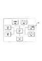
図9は、開示した実施例に対応するRS420のアーキテクチャ例のブロック図である。アーキテクチャ900は、受信ユニット910、バッファユニット920、送信ユニット930、及び制御ユニット940を有することができる。受信ユニット910は、1つ以上のBS410、SS430及び他のRS420からデータを受信するように構成することができ、且つ受信したデータを処理するように構成することができる。バッファユニット920は、受信ユニット910によって処理したデータをバッファリングするように構成することができる。例えば、バッファユニット920は、当該データを識別したり、当該データを変更したりすることなどを行うことができる。制御ユニット940は、入ってくるデータがパケットデータか、又は制御データ、即ちMAPメッセージを含むか否かを判定するように構成することができる。入ってくるデータがパケットデータである場合、制御ユニット940は、例えば再送信、フラグメント化、パッキングなどを含む、1つ以上の処理を実行するように構成することができる。入ってくるデータがMAPメッセージである場合には、制御ユニット940は、制御データを変更するように構成することができる。更に、制御ユニット940は、受信ユニット910及び送信ユニット930用の1つ以上のパラメータを決定するように構成することができる。送信ユニット930は、制御ユニット940によって決定した1つ以上のパラメータに基づいて、バッファユニット920から送られるデータの前処理を実行するように構成することができる。また、送信ユニット930は、データを1つ以上のBS410、SS430及び他のRS420に送信するように構成することもできる。
FIG. 9 is a block diagram of an example RS420 architecture corresponding to the disclosed embodiments. The
図10は、開示した実施例に対応する、アーキテクチャ900を用いてRS420による処理例のフローチャート1000である。1つ以上のBS410、SS430及び他のRS420から送られるデータは、RS420の受信ユニット910によって受信することができる(ステップ1005)。受信ユニット910は、受信したデータの処理を実行することができる(ステップ1010)。該処理は、例えば、復号、復調、アナログ無線信号からディジタル無線信号への変換などを含むことができる。
FIG. 10 is a
受信ユニット910によって提供された情報に基づいて、制御ユニット940は、受信したデータがMAPメッセージであるか否かを判定することができる(スッテプ1015)。受信したデータがMAPメッセージである場合(ステップ1015,Yes)、制御ユニット940は、MAP(例えばMAP IE)における1つ以上の制御データを特定することができる。制御ユニット940は、制御データが自分向けであるか否か、又は制御データが別のRS420又はBS410へと中継されるべきものであるか否かを判定することができる(ステップ1025)。制御データが現在のRS420向けである場合には、制御ユニット940は、接続切替制御データに含まれる伝送パラメータに従って、規定されるタイムスロット及びサブチャネルにおける次のデータバーストを受信するように受信ユニット910を設定することができる。制御ユニット940は、制御データが自分向けでないと判定した場合には、制御ユニット940は、RSタグテーブル450のタグ情報を調べて伝送路における次のノードを決定することができる。更に、制御ユニット940は、1つ以上の伝送パラメータを決定し、当該制御データを送信ユニット930に転送することができる。送信ユニット930は、受信した制御データの前処理を実行することができ(ステップ930)、制御ユニット940によって決定した伝送パラメータに従って、当該データを送信することができる(ステップ1035)。
Based on the information provided by the receiving
受信したデータが制御データでない場合(ステップ1015,No)、制御ユニット940は、データ処理を実行することができる(ステップ1020)。例えば、当該データを受信するRS420の制御ユニット940は、データバーストを更なる処理無しで次のノードに転送するように送信ユニット930を設定することができる。受信したデータがパケットデータであり、且つ該受信するRS420向けである場合、制御ユニット940は、データバースト内に埋め込まれた、及び/又は接続セットアップ中に設定された制御データをデコードすることができる。また、制御ユニット940は、指示されるタイムスロット及びサブチャネルの適用範囲内で1つ以上のSS430用の関連の接続切替制御データ及びパケットデータを送信するように送信ユニット930を設定し(ステップ1025)、当該データを送信ユニット930に転送することができる。送信ユニット930は、受信した制御データの前処理を実行し(ステップ1030)、制御ユニット940によって決定した伝送パラメータに従って当該データを送信することができる(ステップ1035)。
If the received data is not control data (
図11は、タグ切替ネットワーク400におけるBS110からの通信例を示す図である。図11に示すように、ネットワーク400は、RS420d、420e及び420f、及びSS430s、430t、430u及び430zを含むように拡張させている。一実施例では、BS110は、1つ以上のBSタグテーブル440を格納することができる。1つ以上のBSタグテーブル440は、1つ以上の中継ノードと関連付けられたデータ、1つ以上の伝送路、及び/又は1つ以上の伝送路識別子を含むことができる。図11に示すように、BSタグテーブル440は、6つの伝送路、即ち伝送路1(即ち、BS410からRS420aへの伝送路)、伝送路2(即ち、BS410からRS420bへの伝送路)、伝送路3(即ち、BS410からRS420cへの伝送路)、伝送路4(即ち、BS410からRS420dへの伝送路)、伝送路5(即ち、BS410からRS420eへの伝送路)、伝送路6(即ち、BS410からRS420fへの伝送路)を識別することができる。
FIG. 11 is a diagram illustrating an example of communication from the
更に、BSタグテーブル440は、1つ以上の伝送路と1つ以上のSS430との関係を識別することができる。例えば、BSタグテーブル440は、伝送路1によって通信するときのSS430t(即ち、“t”)を、伝送路2によって通信するときのSS430u(即ち、“u”)を、伝送路3によって通信するときのSS430w、430x及び430y(即ち、“w”、“x”及び“y”)を、伝送路6によって通信するときのSS430z(即ち、“z”)を識別することができる。更に、BSタグテーブル440は、SS430がBS410によって通信することを指示することができる。BSタグテーブル440がSS430に対して提供される情報の重複又はオーバーラップがないことを示す間、単一のSS430は、1つ以上の伝送路によって情報を受信することができる。例えばSS430は、RS420c及びRS420fから情報を受信することができ、これによりSS430yは、RS420c及びRS420fに対する伝送路と関連付けることができる。図11に表しているように、“y”は、BSタグテーブル440に示す“3”と同一の行に現れるだけでなく、“6”と同一の行にも現れることになる(図示せず)。
Furthermore, the BS tag table 440 can identify the relationship between one or more transmission paths and one or
一実施例では、各RS420は、1つ以上のRSタグテーブル450を格納することができる。RS420aは、RS420b、RS420c、RS420e、及びRS420fに対して上位のRS420であり、且つこれらの下位のRS420の各々に対する伝送路にある。例えば、RSタグテーブル450aは、4つの伝送路、即ち、伝送路2(即ち、RS420bへの伝送路)、伝送路3(即ち、RS420cへの伝送路)、伝送路5(即ち、RS420eへの伝送路)、及び伝送路6(即ち、RS420fへの伝送路)を識別することができる。更に、RSタグテーブル450aは、SS430tがRS420aによって情報提供される旨を指示することができる。RS420bは、RS420c及びRS420fに対して上位のRS420であり、且つ下位のRS420の各々に対する伝送路にあるので、RSタグテーブル450bは、2つの伝送路、即ち伝送路3(即ち、RS420cへの伝送路)及び伝送路6(即ち、RS420fへの伝送路)を識別することができる。更に、RSタグテーブル450bは、SS430uがRS420bによって情報提供される旨を指示することができる。RS420cのRSタグテーブル450cは、RS420cが下位のRS420を有していないので伝送路情報は含まなくともよい。しかしながら、RSタグテーブル450cは、SS430w、SS430x及びSS430yは、RS420cによって情報提供される旨を指示することができる。同様に、RS420fのRSタグテーブル450fは、RS420fが下位のRS420を有していないので、伝送路情報は含まなくともよい。しかしながら、RSタグテーブル450fは、SS430zがRS420fによって情報提供される旨を指示することができる。RS420d及びRS420eは、RS420d及びRS420eが下位のRS420を有しておらず、且つ如何なるSS430への情報も提供しないので、RSタグテーブル450を持たなくともよく、又はRSタグテーブル450にそれらのデータを持たせなくともよい。
In one embodiment, each
図11の例では、BS410は、SS430s、SS430t、SS430u、SS430w、SS430x、SS430y及びSS430z用のデータを受信することができる。BS410は、BSタグテーブル440をアクセスし、各SS430用の伝送路を決定することができ、各伝送路用のタグ切替MAP IEを生成することができる。更に、BS410は、データを受信する各SS430用の接続切替制御データを生成することができる。BS410は、接続切替制御データをデータバースト領域に置くことができ、関連付けられたタグ切替制御データをフレームMAP IEスロットやMACヘッダに、又はその双方に置くことができる。例えば、BS410とRS420aとの間のデータフレーム460を参照して、BS410は、4つのタグ切替制御データ(フレームのデータバースト領域と関連付けられた各タグ切替制御データ)を含むフレームを送ることができる。即ち、タグ切替制御データ1は、データバースト領域tと対応させることができ、タグ切替制御データ2は、データバースト領域uと対応させることができ、タグ切替制御データ3は、データバースト領域wxyと対応させることができ、タグ切替制御データ6は、データバースト領域zと対応させることができる。一旦、BS410がフレームの処理を完了させると、BS410は、当該フレームを伝送路における次のノード、即ちRS420aに送信することができる。
In the example of FIG. 11, the
RS420aは、データフレーム460を受信して、各タグ切替制御データを処理することができる。この例では、データフレーム460は、4つタグ切替制御データを含むことができる。RS420aは、タグ切替制御データ1に含まれるタグがRS420aを識別するものであると決定することができ、RS420aは、データバースト領域tの接続切替制御データをデコードすることができる。また、RS420aは、接続切替制御データのパラメータに従って、データバースト領域tに含められる関連データをSS430tに送信することができる。
The
RS420aは、タグ切替制御データ2、3及び6がRS420a向けでないということを決定することができ、RS420aは、タグ切替制御データにて見つけられるタグを用いてRSタグテーブル450aをアクセスして、各々のノード用の伝送路における次のノードを決定することができる。この例では、RS420aは、RS420bが次のノードであるということを決定することができ、RS420aは、残りのフレームデータをデータフレーム470としてRS420bに転送することができる。しかしながら、RS420aは、次のノードがRS420aの伝送路にないということを決定する場合には、RS420aは、当該フレームをドロップすることができる。例えば、RS420aは、データをRS420b及びRS420eに転送し、RS420d宛てのデータをドロップすることができる。
The
RS420bは、データフレーム470を受信して、各タグ切替制御データを処理することができる。この例では、データフレーム470は、3つのタグ切替制御データを含んでいる。RS420bは、タグ切替制御データ2に含まれるタグがRS420bを識別するものであることを決定でき、RS420bは、対応するデータバースト領域uの接続切替制御データをデコードすることができる。RS420bは、接続切替制御データのパラメータに従って、データバースト領域uにも含められる関連データをSS430uに送信することができる。
The
RS420bは、フレーム制御データ3及び6がRS420b向けではないということを決定することができ、RS420bは、タグ切替制御データにて見つけられるタグを用いてRSタグテーブル450bをアクセスして、伝送路における次のノードを決定することができる。この例では、RS420bは、RS420cが制御データ3に対応するフレームデータ用の次のノードであり、RS420fが制御データ6に対応するフレームデータ用の次のノードであるということを決定することができる。RS420bは、制御データ3に対応するフレームデータをデータフレーム480としてRS420cに転送し、制御データ6に対応するフレームデータをデータフレーム490としてRS420fに転送することができる。しかしながら、RS420bは、次のノードがRS420bの伝送路にないということを決定する場合には、RS420bは、当該フレームをドロップする。例えば、RS420bは、データをRS420c及びRS420fに転送し、RS420d及びRS420e宛てのデータをドロップすることができる。
The
RS420cは、データフレーム480を受信して、各タグ切替制御データを処理することができる。この例では、データフレーム480は、1つのタグ切替制御データのみを含むことができる。RS420cは、タグ切替制御データ3に含まれるタグがRS420cを識別するものであることを決定することができ、RS420cは、データバースト領域wxyの接続切替制御データをデコードすることができる。RS420cは、各SS430用の接続切替制御データのパラメータに従って、データバースト領域wxyに含められる関連データをSS430w、SS430x及びSS430yに送信することができる。
The
同様に、RS420fは、データフレーム490を受信して、各タグ切替制御データを処理することができる。この例では、データフレーム490は、1つのタグ切替制御データのみを含むことができる。RS420fは、タグ切替制御データ6に含まれるタグがRS420fを識別するものであることを決定することができ、RS420fは、データバースト領域zの接続切替制御データをデコードすることができる。RS420fは、接続切替制御データに従って、データバースト領域zにも含められる関連データをSS430zに送信することができる。
Similarly, the
このように、ネットワーク400は、1つ以上の接続切替制御データを1つ以上のタグ切替制御データに置き換えることによって、1つ以上の中継ノードを用いてデータを送受信することができる。
Thus, the
開示した実施例は、IEEE802.16ファミリの規格に基づいたタグ切替ネットワークを示しているが、開示した実施例は、データを1つ以上の他のネットワークノードに送信又は再送信するように構成することができる、1つ以上のネットワークノードを利用する如何なるネットワークでも実現させることができる。開示した実施例は、改善した性能を得ることができる。特に、開示した実施例は、簡素化したネットワークノードアキテクチャを提供し、無線通信接続の管理を改良し、パケット切替処理の速度を高め、リソース利用を改善することができる。 Although the disclosed embodiment illustrates a tag switching network based on the IEEE 802.16 family of standards, the disclosed embodiment is configured to transmit or retransmit data to one or more other network nodes. Any network that uses one or more network nodes can be implemented. The disclosed embodiments can provide improved performance. In particular, the disclosed embodiments can provide a simplified network node architecture, improve management of wireless communication connections, increase packet switching processing speed, and improve resource utilization.
タグ切替無線伝送のシステム及び方法において、様々な変更及び変形を行うことができることは当業者に明らかである。規格及び例示した態様は単なる例であるとみなすべきであり、開示した実施例の真の範囲は、添付の特許請求の範囲及びその等価なものによって示されていることを意図するものである。 It will be apparent to those skilled in the art that various modifications and variations can be made in the tag switched wireless transmission system and method. The standards and illustrated aspects are to be considered merely exemplary, with the true scope of the disclosed embodiments being intended to be indicated by the appended claims and their equivalents.
Claims (63)
前記複数の中間ノードの各々に対する少なくとも1つの伝送路であって、前記少なくとも1つの伝送路に沿った全ての中間ノードと関連付けられたデータを転送する前記少なくとも1つの伝送路を決定するステップと、
前記少なくとも1つの伝送路の各々用の、宛先ノード識別子となる伝送路識別子を決定するステップと、
少なくとも1つの前記伝送路識別子に基づいて送信される伝送データを前記複数の宛先機器のうちの少なくとも1つの宛先機器に送信するステップと、
を含み、
前記伝送データは、前記伝送路識別子を含み、
前記伝送路識別子は、少なくとも1つの宛先ノードを識別する情報を含み、かつ、前記中間ノードの位置を識別する情報を含まない、無線データ処理方法。 A method for processing wireless data in a multi-hop relay based wireless communication network including a plurality of intermediate nodes and a plurality of destination devices, comprising:
Determining at least one transmission path for each of the plurality of intermediate nodes, the at least one transmission path transferring data associated with all intermediate nodes along the at least one transmission path;
Determining a transmission path identifier to be a destination node identifier for each of the at least one transmission path;
Transmitting transmission data to be transmitted based on at least one transmission path identifier to at least one destination device of the plurality of destination devices;
Only including,
The transmission data includes the transmission path identifier,
The wireless data processing method , wherein the transmission path identifier includes information for identifying at least one destination node and does not include information for identifying a position of the intermediate node .
前記複数の中間ノードの各々に対して、前記伝送路を転送するデータと、各中間ノードが含まれている前記少なくとも1つの伝送路の各伝送路用の伝送路識別子とを提供するステップを更に含む、請求項1に記載の無線データ処理方法。 Each of the plurality of intermediate nodes is included in at least one transmission path;
Providing each of the plurality of intermediate nodes with data for transferring the transmission line and a transmission line identifier for each transmission line of the at least one transmission line in which each intermediate node is included; The wireless data processing method according to claim 1, further comprising:
データ及び命令を格納するための少なくとも1つのメモリと、
前記メモリにアクセスするように構成された少なくとも1つのプロセッサとを備え、
前記少なくとも1つのプロセッサは、命令を実行するときに、
前記複数の中間ノードの各々に対する少なくとも1つの伝送路であって、前記少なくとも1つの伝送路に沿った全ての中間ノードと関連付けられたデータを転送する前記少なくとも1つの伝送路を決定し、
前記少なくとも1つの伝送路の各々用の、宛先ノード識別子となる伝送路識別子を決定し、
少なくとも1つの前記伝送路識別子に基づいて送信される伝送データを前記複数の宛先機器のうちの少なくとも1つの宛先機器に送信するように構成され、
前記伝送データは、前記伝送路識別子を含み、
前記伝送路識別子は、少なくとも1つの宛先ノードを識別する情報を含み、かつ、前記中間ノードの位置を識別する情報を含まない、無線通信ステーション。 A wireless communication station for wireless communication in a multi-hop relay-based wireless communication network including a plurality of intermediate nodes and a plurality of destination devices,
At least one memory for storing data and instructions;
And at least one processor configured to access the memory;
The at least one processor executes instructions when
Determining at least one transmission path for each of the plurality of intermediate nodes, the at least one transmission path transferring data associated with all intermediate nodes along the at least one transmission path;
Determining a transmission path identifier to be a destination node identifier for each of the at least one transmission path;
Configured to transmit transmission data transmitted based on at least one of the transmission path identifiers to at least one destination device of the plurality of destination devices ;
The transmission data includes the transmission path identifier,
The wireless communication station , wherein the transmission path identifier includes information identifying at least one destination node, and does not include information identifying a position of the intermediate node .
受信ユニットによって、少なくとも1つの第1制御データ及び少なくとも1つの第2制御データを含む伝送データを受信するステップであって、前記少なくとも1つの第1制御データの各々は各伝送路を識別することができるタグ切替接続識別子を含み、前記少なくとも1つの第2制御データの各々は伝送路識別子を含み、前記伝送路識別子は宛先ノード識別子となる、該伝送データを受信するステップと、
前記受信ユニットによって、前記伝送データを処理するステップと、
バッファユニットによって、前記受信ユニットと通信して処理したデータをバッファリングするステップと、
送信ユニットによって、バッファユニットと通信してバッファユニットからバッファリングしたデータを受信するステップと、
前記バッファリングしたデータの送信前処理を実行するステップと、
制御ユニットによって、前記受信ユニット、前記バッファユニット及び前記送信ユニットと通信して、前記受信ユニットと関連付けられた1つ以上の受信パラメータを設定するステップと、を含み、
前記伝送路識別子は、少なくとも1つの宛先ノードを識別する情報を含み、かつ、前記中間ノードの位置を識別する情報を含まない、データ処理実行方法。 A method for performing data processing at an intermediate node in a multi-hop relay based wireless communication network including a plurality of intermediate nodes and a plurality of destination devices, comprising :
Receiving transmission data including at least one first control data and at least one second control data by a receiving unit, wherein each of the at least one first control data identifies each transmission path; Receiving the transmission data, wherein each of the at least one second control data includes a transmission path identifier, and the transmission path identifier is a destination node identifier;
Processing the transmission data by the receiving unit;
Buffering data processed by communicating with the receiving unit by a buffer unit;
Communicating with the buffer unit by the transmitting unit to receive buffered data from the buffer unit;
Performing pre-transmission processing of the buffered data;
By the control unit, the receiving unit, in communication with the buffer unit and the transmission unit, viewed including the steps of: setting one or more receiving parameters associated with the receiver unit,
The data processing execution method , wherein the transmission path identifier includes information identifying at least one destination node, and does not include information identifying a position of the intermediate node .
少なくとも1つの第1制御データ及び少なくとも1つの第2制御データを含む伝送データを受信して処理するように動作可能な受信ユニットであって、前記少なくとも1つの第1制御データの各々は各伝送路を識別することができるタグ切替接続識別子を含み、前記少なくとも1つの第2制御データの各々は伝送路識別子を含み、前記伝送路識別子は宛先ノード識別子となる、受信ユニットと、
前記受信ユニットと通信して前記処理したデータをバッファリングするように構成されるバッファユニットと、
前記バッファユニットと通信して前記バッファユニットからバッファリングしたデータを受信するように構成される送信ユニットと、
前記受信ユニット、前記バッファユニット及び前記送信ユニットと通信して、 前記受信ユニットと関連付けられた1つ以上の受信パラメータを設定するように動作する制御ユニットと、を備え、
前記伝送路識別子は、少なくとも1つの宛先ノードを識別する情報を含み、かつ、前記中間ノードの位置を識別する情報を含まない、中間ノード。 An intermediate node for performing data processing in a multi-hop relay-based wireless communication network including a plurality of intermediate nodes and a plurality of destination devices ,
A receiving unit operable to receive and process transmission data including at least one first control data and at least one second control data, wherein each of the at least one first control data is a transmission line. A receiving unit in which each of the at least one second control data includes a transmission path identifier, and the transmission path identifier is a destination node identifier;
A buffer unit configured to communicate with the receiving unit to buffer the processed data;
A transmission unit configured to communicate with the buffer unit and receive buffered data from the buffer unit;
A control unit operable to communicate with the receiving unit, the buffer unit, and the transmitting unit to set one or more receiving parameters associated with the receiving unit ;
The transmission path identifier includes information identifying at least one destination node, and does not include information identifying the position of the intermediate node.
前記複数の宛先機器のうちの少なくとも1つの宛先機器への伝送データを用意するステップと、
前記少なくとも1つの宛先機器によって前記宛先中間ノードと通信することになる、前記宛先中間ノードに対する伝送路を決定するステップと、
前記少なくとも1つの宛先機器に関連付けられた1つ以上のパラメータを含む第1制御データを当該データに割り当てるステップと、
宛先ノード識別子となる伝送路識別子を含む第2制御データを当該データに割り当てるステップと、
当該データを含む少なくとも1つの伝送フレームを該伝送路に沿って送信するステップと、を含み、
前記伝送路識別子は、少なくとも1つの宛先ノードを識別する情報を含み、かつ、前記中間ノードの位置を識別する情報を含まない、データ処理方法。 A method for processing data in a multi-hop relay-based wireless communication network including a plurality of intermediate nodes and a plurality of destination devices, comprising:
Comprising the steps of: providing a heat Okude over data to at least one destination device of the plurality of destination devices,
Determining a transmission path for the destination intermediate node to be communicated with the destination intermediate node by the at least one destination device;
Assigning to the data first control data including one or more parameters associated with the at least one destination device;
Assigning second control data including a transmission path identifier to be a destination node identifier to the data;
A step of at least one transmission frame including the data transmitted along the transmission path, viewed contains a
The data processing method , wherein the transmission path identifier includes information for identifying at least one destination node, and does not include information for identifying a position of the intermediate node .
データ及び命令を格納する少なくとも1つのメモリと、
前記メモリとアクセスするように構成される少なくとも1つのプロセッサとを備え、
前記少なくとも1つのプロセッサは、命令を実行するときに、
前記複数の宛先機器のうちの少なくとも1つの宛先機器への伝送データを用意し、
前記少なくとも1つの宛先機器によって前記宛先中間ノードと通信することになる、宛先中間ノードに対する伝送路を決定し、
前記少なくとも1つの宛先機器と関連付けられた1つ以上のパラメータを含む第1制御データを当該データに割り当て、
宛先ノード識別子となる伝送路識別子を含む第2制御データを当該データに割り当て、
当該データを含む少なくとも1つの伝送フレームを伝送路に沿って送信するように構成されており、
前記伝送路識別子は、少なくとも1つの宛先ノードを識別する情報を含み、かつ、前記中間ノードの位置を識別する情報を含まない、無線通信ステーション。 A wireless communication station for wireless communication in a multi-hop relay-based wireless communication network including a plurality of intermediate nodes and a plurality of destination devices,
At least one memory for storing data and instructions;
And at least one processor configured to access the memory;
The at least one processor executes instructions when
Providing a heat Okude over data to at least one destination device of the plurality of destination devices,
Determining a transmission path for the destination intermediate node to be communicated with the destination intermediate node by the at least one destination device;
Assigning to the data first control data including one or more parameters associated with the at least one destination device;
Assigning second control data including a transmission path identifier to be a destination node identifier to the data;
It is configured to transmit at least one transmission frame including the data along the transmission path ,
The wireless communication station , wherein the transmission path identifier includes information identifying at least one destination node, and does not include information identifying a position of the intermediate node .
複数の宛先機器のうちの少なくとも1つの宛先機器用の宛先機器データ、少なくとも1つの第1制御データ、及び少なくとも1つの第2制御データを含む伝送データを受信するステップであって、前記少なくとも1つの第1制御データの各々は各伝送路を識別することができるタグ切替接続識別子を含み、前記少なくとも1つの第2制御データの各々は伝送路識別子を含み、前記伝送路識別子は宛先ノード識別子となる、該データを受信するステップと、
前記少なくとも1つの第2制御データの各々における伝送路識別子を評価するステップと、
前記伝送路識別子に基づいて当該データを処理するステップと、を含み、
前記伝送路識別子は、少なくとも1つの宛先ノードを識別する情報を含み、かつ、前記中間ノードの位置を識別する情報を含まない、データ処理方法。 A method for processing data by an intermediate node in a multi-hop relay-based wireless communication network including a plurality of intermediate nodes and a plurality of destination devices, comprising:
Receiving transmission data including destination device data for at least one destination device of a plurality of destination devices, at least one first control data, and at least one second control data, the at least one Each of the first control data includes a tag switching connection identifier capable of identifying each transmission path, each of the at least one second control data includes a transmission path identifier, and the transmission path identifier is a destination node identifier. Receiving the data; and
Evaluating a transmission path identifier in each of the at least one second control data;
Look including the steps of: processing the data based on the transmission path identifier,
The data processing method , wherein the transmission path identifier includes information for identifying at least one destination node, and does not include information for identifying a position of the intermediate node .
前記少なくとも1つの第2制御データに含まれる前記伝送路識別子に基づいて、宛先中間ノードを決定するステップを含む、請求項48に記載のデータ処理方法。 Processing the data comprises:
49. The data processing method according to claim 48, further comprising: determining a destination intermediate node based on the transmission path identifier included in the at least one second control data.
前記少なくとも1つの第2制御データによって特定した次のノードが、前記中間ノードと同一の伝送路にあるか否かを判定するステップを更に含む、請求項48に記載のデータ処理方法。 Processing the data comprises:
49. The data processing method according to claim 48, further comprising the step of determining whether or not a next node specified by the at least one second control data is on the same transmission path as the intermediate node.
データ及び命令を格納する少なくとも1つのメモリと、
前記メモリとアクセスするように構成される少なくとも1つのプロセッサとを備え、
前記少なくとも1つのプロセッサは、命令を実行するときに、
前記複数の宛先機器のうちの少なくとも1つの宛先機器用の宛先機器データと、少なくとも1つの第1制御データと、少なくとも1つの第2制御データとを含む伝送データを受信するように構成され、且つ、前記少なくとも1つの第1制御データの各々は各伝送路を識別することができるタグ切替接続識別子を含み、前記少なくとも1つの第2制御データの各々は伝送路識別子を含み、前記伝送路識別子は宛先ノード識別子であり、
前記少なくとも1つの第2制御データの各々における伝送路識別子を評価し、
前記伝送路識別子に基づいて当該データを処理するように構成され、
前記伝送路識別子は、少なくとも1つの宛先ノードを識別する情報を含み、かつ、前記中間ノードの位置を識別する情報を含まない、中間ノード。 An intermediate node in a multi-hop relay-based wireless communication network including a plurality of intermediate nodes and a plurality of destination devices,
At least one memory for storing data and instructions;
And at least one processor configured to access the memory;
The at least one processor executes instructions when
Configured to receive transmission data including destination device data for at least one destination device of the plurality of destination devices, at least one first control data, and at least one second control data; and Each of the at least one first control data includes a tag switching connection identifier capable of identifying each transmission path, each of the at least one second control data includes a transmission path identifier, and the transmission path identifier is The destination node identifier,
Evaluating a channel identifier in each of the at least one second control data;
Configured to process the data based on the transmission path identifier ;
The transmission path identifier includes information identifying at least one destination node, and does not include information identifying the position of the intermediate node.
Applications Claiming Priority (2)
| Application Number | Priority Date | Filing Date | Title |
|---|---|---|---|
| US84267506P | 2006-09-07 | 2006-09-07 | |
| US60/842,675 | 2006-09-07 |
Publications (2)
| Publication Number | Publication Date |
|---|---|
| JP2008104159A JP2008104159A (en) | 2008-05-01 |
| JP5192201B2 true JP5192201B2 (en) | 2013-05-08 |
Family
ID=39192948
Family Applications (1)
| Application Number | Title | Priority Date | Filing Date |
|---|---|---|---|
| JP2007221291A Active JP5192201B2 (en) | 2006-09-07 | 2007-08-28 | Wireless communication system and method |
Country Status (2)
| Country | Link |
|---|---|
| JP (1) | JP5192201B2 (en) |
| CN (1) | CN101141175B (en) |
Families Citing this family (6)
| Publication number | Priority date | Publication date | Assignee | Title |
|---|---|---|---|---|
| US8483041B2 (en) * | 2008-06-12 | 2013-07-09 | Qualcomm Incorporated | Methods and systems for sticky region allocation in OFDMA communication systems |
| US8902805B2 (en) * | 2008-10-24 | 2014-12-02 | Qualcomm Incorporated | Cell relay packet routing |
| US20100103911A1 (en) * | 2008-10-28 | 2010-04-29 | Samsung Electronics, Co., Ltd. | Apparatus and method providing an IEEE-802.16 self-organizing network |
| US8565184B2 (en) * | 2009-02-20 | 2013-10-22 | Lg Electronics Inc. | Method for allocating reference signals of a backhaul link in a relay communication system, and method and apparatus for transmitting/receiving data using same |
| US9871884B2 (en) | 2014-09-30 | 2018-01-16 | Xiaomi Inc. | Method and device for transferring messages |
| CN104243288B (en) * | 2014-09-30 | 2015-12-02 | 小米科技有限责任公司 | Method for message transmission and device, electronic equipment |
Family Cites Families (5)
| Publication number | Priority date | Publication date | Assignee | Title |
|---|---|---|---|---|
| US5570084A (en) * | 1994-06-28 | 1996-10-29 | Metricom, Inc. | Method of loose source routing over disparate network types in a packet communication network |
| US6842430B1 (en) * | 1996-10-16 | 2005-01-11 | Koninklijke Philips Electronics N.V. | Method for configuring and routing data within a wireless multihop network and a wireless network for implementing the same |
| JP4014893B2 (en) * | 2002-03-01 | 2007-11-28 | 株式会社エヌ・ティ・ティ・ドコモ | Wireless communication system for multi-hop connection, wireless communication method, and wireless station used therefor |
| US7433332B2 (en) * | 2003-04-30 | 2008-10-07 | Skypipes Wireless, Inc. | Managed microcell wireless mesh network architecture |
| WO2006001308A1 (en) * | 2004-06-24 | 2006-01-05 | Matsushita Electric Industrial Co., Ltd. | Radio system, radio node device, and path control device |
-
2007
- 2007-08-28 JP JP2007221291A patent/JP5192201B2/en active Active
- 2007-09-03 CN CN2007101488169A patent/CN101141175B/en active Active
Also Published As
| Publication number | Publication date |
|---|---|
| CN101141175A (en) | 2008-03-12 |
| JP2008104159A (en) | 2008-05-01 |
| CN101141175B (en) | 2012-04-18 |
Similar Documents
| Publication | Publication Date | Title |
|---|---|---|
| KR100940925B1 (en) | Wireless communication system and method | |
| EP2323441B1 (en) | Method of transmitting a message in a mesh network having a maximum number of next hop addresses | |
| EP1932286B1 (en) | Method and system for a wireless multi-hop relay network | |
| JP5134136B2 (en) | Communication method and apparatus using physical connection point identifier supporting dual communication link | |
| JP5642765B2 (en) | Pseudowiring for mobility management | |
| US8259702B2 (en) | Efficient over the air address methods and apparatus | |
| JP4711844B2 (en) | Uplink channel configuration in wireless communication system | |
| JP5191202B2 (en) | Wireless communication system, method, and data structure | |
| MX2008014927A (en) | Systems, methods and apparatus for allocating time slots in an ad hoc wireless communication network. | |
| JP2008118659A (en) | Centralized-scheduler relay station for mmr extended 802.16e system | |
| JP5192201B2 (en) | Wireless communication system and method | |
| WO2008071112A1 (en) | Method of resource schedule for a wireless system and system thereof | |
| US20230038562A1 (en) | Methods and infrastructure equipment | |
| KR20110053257A (en) | Proxy mechanism for mesh-type networks | |
| US20080043747A1 (en) | Apparatus, method, system and software product for a scheduling synchronization mechanism in a multi-hop environment | |
| JPWO2012172689A1 (en) | COMMUNICATION SYSTEM, DATA RELAY DEVICE, BASE STATION, MOBILE TERMINAL AND COMMUNICATION METHOD | |
| WO2011044839A1 (en) | Method for data transmission based on relay mobile communication system and equipment thereof | |
| JP5415450B2 (en) | Flexible control channel for unplanned wireless networks | |
| US20230134743A1 (en) | Frequency domain resource configuration in iab | |
| WO2023202534A1 (en) | Multi-hop transmission method and communication apparatus | |
| JP2023541109A (en) | Communication method and device and readable storage medium | |
| JP5122629B2 (en) | Base station for transmitting downlink signal of wireless communication system | |
| CN115190558A (en) | Communication method and communication equipment | |
| WO2014186985A1 (en) | Communication device and wireless communication method | |
| WO2009003320A1 (en) | A method and device for controlling synchronous transmission of service data packet in base station and repeaters |
Legal Events
| Date | Code | Title | Description |
|---|---|---|---|
| A131 | Notification of reasons for refusal |
Free format text: JAPANESE INTERMEDIATE CODE: A131 Effective date: 20100330 |
|
| A521 | Request for written amendment filed |
Free format text: JAPANESE INTERMEDIATE CODE: A523 Effective date: 20100630 |
|
| A02 | Decision of refusal |
Free format text: JAPANESE INTERMEDIATE CODE: A02 Effective date: 20100720 |
|
| A521 | Request for written amendment filed |
Free format text: JAPANESE INTERMEDIATE CODE: A523 Effective date: 20101119 |
|
| A911 | Transfer to examiner for re-examination before appeal (zenchi) |
Free format text: JAPANESE INTERMEDIATE CODE: A911 Effective date: 20101126 |
|
| A912 | Re-examination (zenchi) completed and case transferred to appeal board |
Free format text: JAPANESE INTERMEDIATE CODE: A912 Effective date: 20101224 |
|
| A601 | Written request for extension of time |
Free format text: JAPANESE INTERMEDIATE CODE: A601 Effective date: 20121003 |
|
| A602 | Written permission of extension of time |
Free format text: JAPANESE INTERMEDIATE CODE: A602 Effective date: 20121009 |
|
| A521 | Request for written amendment filed |
Free format text: JAPANESE INTERMEDIATE CODE: A523 Effective date: 20121105 |
|
| A61 | First payment of annual fees (during grant procedure) |
Free format text: JAPANESE INTERMEDIATE CODE: A61 Effective date: 20130131 |
|
| R150 | Certificate of patent or registration of utility model |
Free format text: JAPANESE INTERMEDIATE CODE: R150 Ref document number: 5192201 Country of ref document: JP Free format text: JAPANESE INTERMEDIATE CODE: R150 |
|
| FPAY | Renewal fee payment (event date is renewal date of database) |
Free format text: PAYMENT UNTIL: 20160208 Year of fee payment: 3 |
|
| R250 | Receipt of annual fees |
Free format text: JAPANESE INTERMEDIATE CODE: R250 |
|
| R250 | Receipt of annual fees |
Free format text: JAPANESE INTERMEDIATE CODE: R250 |
|
| R250 | Receipt of annual fees |
Free format text: JAPANESE INTERMEDIATE CODE: R250 |
|
| R250 | Receipt of annual fees |
Free format text: JAPANESE INTERMEDIATE CODE: R250 |
|
| R250 | Receipt of annual fees |
Free format text: JAPANESE INTERMEDIATE CODE: R250 |
|
| R250 | Receipt of annual fees |
Free format text: JAPANESE INTERMEDIATE CODE: R250 |
|
| R250 | Receipt of annual fees |
Free format text: JAPANESE INTERMEDIATE CODE: R250 |
|
| R250 | Receipt of annual fees |
Free format text: JAPANESE INTERMEDIATE CODE: R250 |
|
| R250 | Receipt of annual fees |
Free format text: JAPANESE INTERMEDIATE CODE: R250 |