JP5191745B2 - Hydrogen generating fuel cell cartridge - Google Patents
Hydrogen generating fuel cell cartridge Download PDFInfo
- Publication number
- JP5191745B2 JP5191745B2 JP2007557110A JP2007557110A JP5191745B2 JP 5191745 B2 JP5191745 B2 JP 5191745B2 JP 2007557110 A JP2007557110 A JP 2007557110A JP 2007557110 A JP2007557110 A JP 2007557110A JP 5191745 B2 JP5191745 B2 JP 5191745B2
- Authority
- JP
- Japan
- Prior art keywords
- reaction chamber
- reactant
- gas
- pressure
- valve
- Prior art date
- Legal status (The legal status is an assumption and is not a legal conclusion. Google has not performed a legal analysis and makes no representation as to the accuracy of the status listed.)
- Expired - Fee Related
Links
Images


Classifications
-
- H—ELECTRICITY
- H01—ELECTRIC ELEMENTS
- H01M—PROCESSES OR MEANS, e.g. BATTERIES, FOR THE DIRECT CONVERSION OF CHEMICAL ENERGY INTO ELECTRICAL ENERGY
- H01M8/00—Fuel cells; Manufacture thereof
- H01M8/04—Auxiliary arrangements, e.g. for control of pressure or for circulation of fluids
- H01M8/04082—Arrangements for control of reactant parameters, e.g. pressure or concentration
- H01M8/04201—Reactant storage and supply, e.g. means for feeding, pipes
- H01M8/04208—Cartridges, cryogenic media or cryogenic reservoirs
-
- B—PERFORMING OPERATIONS; TRANSPORTING
- B01—PHYSICAL OR CHEMICAL PROCESSES OR APPARATUS IN GENERAL
- B01J—CHEMICAL OR PHYSICAL PROCESSES, e.g. CATALYSIS OR COLLOID CHEMISTRY; THEIR RELEVANT APPARATUS
- B01J4/00—Feed or outlet devices; Feed or outlet control devices
- B01J4/02—Feed or outlet devices; Feed or outlet control devices for feeding measured, i.e. prescribed quantities of reagents
-
- B—PERFORMING OPERATIONS; TRANSPORTING
- B01—PHYSICAL OR CHEMICAL PROCESSES OR APPARATUS IN GENERAL
- B01J—CHEMICAL OR PHYSICAL PROCESSES, e.g. CATALYSIS OR COLLOID CHEMISTRY; THEIR RELEVANT APPARATUS
- B01J7/00—Apparatus for generating gases
- B01J7/02—Apparatus for generating gases by wet methods
-
- C—CHEMISTRY; METALLURGY
- C01—INORGANIC CHEMISTRY
- C01B—NON-METALLIC ELEMENTS; COMPOUNDS THEREOF; METALLOIDS OR COMPOUNDS THEREOF NOT COVERED BY SUBCLASS C01C
- C01B3/00—Hydrogen; Gaseous mixtures containing hydrogen; Separation of hydrogen from mixtures containing it; Purification of hydrogen
- C01B3/02—Production of hydrogen or of gaseous mixtures containing a substantial proportion of hydrogen
- C01B3/06—Production of hydrogen or of gaseous mixtures containing a substantial proportion of hydrogen by reaction of inorganic compounds containing electro-positively bound hydrogen, e.g. water, acids, bases, ammonia, with inorganic reducing agents
- C01B3/065—Production of hydrogen or of gaseous mixtures containing a substantial proportion of hydrogen by reaction of inorganic compounds containing electro-positively bound hydrogen, e.g. water, acids, bases, ammonia, with inorganic reducing agents from a hydride
-
- C—CHEMISTRY; METALLURGY
- C01—INORGANIC CHEMISTRY
- C01B—NON-METALLIC ELEMENTS; COMPOUNDS THEREOF; METALLOIDS OR COMPOUNDS THEREOF NOT COVERED BY SUBCLASS C01C
- C01B3/00—Hydrogen; Gaseous mixtures containing hydrogen; Separation of hydrogen from mixtures containing it; Purification of hydrogen
- C01B3/02—Production of hydrogen or of gaseous mixtures containing a substantial proportion of hydrogen
- C01B3/32—Production of hydrogen or of gaseous mixtures containing a substantial proportion of hydrogen by reaction of gaseous or liquid organic compounds with gasifying agents, e.g. water, carbon dioxide, air
-
- H—ELECTRICITY
- H01—ELECTRIC ELEMENTS
- H01M—PROCESSES OR MEANS, e.g. BATTERIES, FOR THE DIRECT CONVERSION OF CHEMICAL ENERGY INTO ELECTRICAL ENERGY
- H01M8/00—Fuel cells; Manufacture thereof
- H01M8/04—Auxiliary arrangements, e.g. for control of pressure or for circulation of fluids
-
- B—PERFORMING OPERATIONS; TRANSPORTING
- B01—PHYSICAL OR CHEMICAL PROCESSES OR APPARATUS IN GENERAL
- B01J—CHEMICAL OR PHYSICAL PROCESSES, e.g. CATALYSIS OR COLLOID CHEMISTRY; THEIR RELEVANT APPARATUS
- B01J2208/00—Processes carried out in the presence of solid particles; Reactors therefor
- B01J2208/00008—Controlling the process
- B01J2208/00539—Pressure
-
- Y—GENERAL TAGGING OF NEW TECHNOLOGICAL DEVELOPMENTS; GENERAL TAGGING OF CROSS-SECTIONAL TECHNOLOGIES SPANNING OVER SEVERAL SECTIONS OF THE IPC; TECHNICAL SUBJECTS COVERED BY FORMER USPC CROSS-REFERENCE ART COLLECTIONS [XRACs] AND DIGESTS
- Y02—TECHNOLOGIES OR APPLICATIONS FOR MITIGATION OR ADAPTATION AGAINST CLIMATE CHANGE
- Y02E—REDUCTION OF GREENHOUSE GAS [GHG] EMISSIONS, RELATED TO ENERGY GENERATION, TRANSMISSION OR DISTRIBUTION
- Y02E60/00—Enabling technologies; Technologies with a potential or indirect contribution to GHG emissions mitigation
- Y02E60/30—Hydrogen technology
- Y02E60/32—Hydrogen storage
-
- Y—GENERAL TAGGING OF NEW TECHNOLOGICAL DEVELOPMENTS; GENERAL TAGGING OF CROSS-SECTIONAL TECHNOLOGIES SPANNING OVER SEVERAL SECTIONS OF THE IPC; TECHNICAL SUBJECTS COVERED BY FORMER USPC CROSS-REFERENCE ART COLLECTIONS [XRACs] AND DIGESTS
- Y02—TECHNOLOGIES OR APPLICATIONS FOR MITIGATION OR ADAPTATION AGAINST CLIMATE CHANGE
- Y02E—REDUCTION OF GREENHOUSE GAS [GHG] EMISSIONS, RELATED TO ENERGY GENERATION, TRANSMISSION OR DISTRIBUTION
- Y02E60/00—Enabling technologies; Technologies with a potential or indirect contribution to GHG emissions mitigation
- Y02E60/30—Hydrogen technology
- Y02E60/36—Hydrogen production from non-carbon containing sources, e.g. by water electrolysis
-
- Y—GENERAL TAGGING OF NEW TECHNOLOGICAL DEVELOPMENTS; GENERAL TAGGING OF CROSS-SECTIONAL TECHNOLOGIES SPANNING OVER SEVERAL SECTIONS OF THE IPC; TECHNICAL SUBJECTS COVERED BY FORMER USPC CROSS-REFERENCE ART COLLECTIONS [XRACs] AND DIGESTS
- Y02—TECHNOLOGIES OR APPLICATIONS FOR MITIGATION OR ADAPTATION AGAINST CLIMATE CHANGE
- Y02E—REDUCTION OF GREENHOUSE GAS [GHG] EMISSIONS, RELATED TO ENERGY GENERATION, TRANSMISSION OR DISTRIBUTION
- Y02E60/00—Enabling technologies; Technologies with a potential or indirect contribution to GHG emissions mitigation
- Y02E60/30—Hydrogen technology
- Y02E60/50—Fuel cells
-
- Y—GENERAL TAGGING OF NEW TECHNOLOGICAL DEVELOPMENTS; GENERAL TAGGING OF CROSS-SECTIONAL TECHNOLOGIES SPANNING OVER SEVERAL SECTIONS OF THE IPC; TECHNICAL SUBJECTS COVERED BY FORMER USPC CROSS-REFERENCE ART COLLECTIONS [XRACs] AND DIGESTS
- Y10—TECHNICAL SUBJECTS COVERED BY FORMER USPC
- Y10T—TECHNICAL SUBJECTS COVERED BY FORMER US CLASSIFICATION
- Y10T137/00—Fluid handling
- Y10T137/8593—Systems
- Y10T137/87917—Flow path with serial valves and/or closures
- Y10T137/87925—Separable flow path section, valve or closure in each
- Y10T137/87941—Each valve and/or closure operated by coupling motion
- Y10T137/87949—Linear motion of flow path sections operates both
Abstract
Description
燃料電池は、直接すなわち、反応物質、すなわち燃料および酸素の化学エネルギを直流(DC)電気に直接変換する装置である。多くの漸増している用途において、燃料電池は、化石燃料の燃焼などの従来の発電よりも効率的であり、リチウムイオンバッテリーなどの携帯型蓄電池より効率的である。 A fuel cell is a device that directly converts the chemical energy of the reactants, ie fuel and oxygen, directly into direct current (DC) electricity. In many increasing applications, fuel cells are more efficient than conventional power generation, such as fossil fuel combustion, and more efficient than portable storage batteries, such as lithium ion batteries.
一般に、燃料電池技術はアルカリ燃料電池、高分子電解質燃料電池、りん酸燃料電池、溶融炭酸塩燃料電池、固体酸化物燃料電池、および酵素燃料電池のような様々な異なった燃料電池を含む。今日のより重要な燃料電池は、3つのカテゴリ、すなわち、(i)圧縮水素(H2)を燃料として利用する燃料電池、(ii)水素燃料に改質されるメタノール(CH3OH)、水素化ホウ素ナトリウム(NaBH4)、炭化水素(例えばブタン)又は他の燃料を利用する陽子交換膜(PEM)燃料電池、(iii)直接に非水素燃料を消費できるPEM燃料電池すなわち直接酸化燃料電池、および、(iv)炭化水素燃料を高熱で直接に電気に変換する固体酸化物燃料電池(SOFC)に分けることができる。 In general, fuel cell technology includes a variety of different fuel cells such as alkaline fuel cells, polymer electrolyte fuel cells, phosphoric acid fuel cells, molten carbonate fuel cells, solid oxide fuel cells, and enzyme fuel cells. Today's more important fuel cells are divided into three categories: (i) fuel cells that use compressed hydrogen (H 2 ) as fuel, (ii) methanol (CH 3 OH) reformed to hydrogen fuel, hydrogen Proton exchange membrane (PEM) fuel cells utilizing sodium borohydride (NaBH 4 ), hydrocarbons (eg butane) or other fuels, (iii) PEM fuel cells that can consume non-hydrogen fuel directly, ie direct oxidation fuel cells, And (iv) It can be divided into a solid oxide fuel cell (SOFC) that converts hydrocarbon fuel directly into electricity with high heat.
圧縮された水素は一般に、高い圧力の下で保たれ、そのため、扱いが難しい。その上、大きい貯蔵タンクが通常必要で、消費者向け電子製品用に十分小さくすることができない。従来の改質燃料電池は、燃料を水素に変換させて燃料電池内で酸素と反応させるために改質材や気化および補助システムを必要とする。最近の進歩により、改質材または改質燃料電池が消費者向け電子製品に有望になっている。最も一般的な直接酸化燃料電池は、ダイレクトメタノール燃料電池すなわちDMFCである。他の直接酸化燃料電池は、ダイレクトエタノール燃料電池およびダイレクトテトラメチルオルトカーボネート燃料電池を含む。DMFCでは、メタノールが直接に燃料電池中で酸素と反応し、このDMFCは、最も簡単で可能性としては最も小さくなる燃料電池であり、消費者向け電子製品用の電力供給に最も有望である。SOFCは炭化水素例えばブタンを高熱で変換して電気を生じる。SOFCは、燃料電池反応を起こさせるために1000°Cの範囲の比較的高温を必要とする。 Compressed hydrogen is generally kept under high pressure and is therefore difficult to handle. Moreover, large storage tanks are usually required and cannot be made small enough for consumer electronic products. Conventional reformed fuel cells require reformers, vaporization and auxiliary systems to convert the fuel to hydrogen and react with oxygen in the fuel cell. Recent advances have made reformate or reformed fuel cells promising for consumer electronic products. The most common direct oxidation fuel cell is a direct methanol fuel cell or DMFC. Other direct oxidation fuel cells include direct ethanol fuel cells and direct tetramethyl orthocarbonate fuel cells. In a DMFC, methanol directly reacts with oxygen in the fuel cell, which is the simplest and possibly the smallest fuel cell and is the most promising power supply for consumer electronic products. SOFC generates electricity by converting hydrocarbons such as butane with high heat. SOFCs require relatively high temperatures in the 1000 ° C. range to cause fuel cell reactions.
電気を発生させる化学反応は燃料電池のそれぞれのタイプごとに異なる。DMFCでは、各電極での化学電気反応と燃料電池に関する総合的な反応は以下の通り記述される: The chemical reaction that generates electricity is different for each type of fuel cell. In DMFC, the chemical and electrical reactions at each electrode and the overall reaction for the fuel cell are described as follows:
陽極での半反応:
CH3OH + H2O → CO2 + 6H+ + 6e−
陰極での半反応:
O2 + 4H+ + 4e− → 2H2O
全体の燃料電池反応:
CH3OH + 1.5O2 → CO2 + 2H2O
Half reaction at the anode:
CH 3 OH + H 2 O → CO 2 + 6H + + 6e −
Semi-reaction at the cathode:
O 2 + 4H + + 4e − → 2H 2 O
Overall fuel cell reaction:
CH 3 OH + 1.5O 2 → CO 2 + 2H 2 O
PEMを通る水素イオン(H+)が陽極から陰極を通り抜けてマイグレーションするために、また、自由電子(e−)がPEMを通り抜けられないため、電子は外部回路を通って流れなければならず、外部回路を通して電流を生じさせる。この外部回路は、モバイルすなわちセル電話、計算機、パーソナルデジタツアシスタンツ、ラップトップコンピュータ、電力ツールなどの有益な消費者向けの電子製品であってよい。 In order for hydrogen ions (H + ) passing through the PEM to migrate from the anode through the cathode and because free electrons (e − ) cannot pass through the PEM, the electrons must flow through the external circuit, An electric current is generated through an external circuit. This external circuit may be a valuable consumer electronic product such as a mobile or cell phone, a calculator, a personal digital assistant, a laptop computer, a power tool or the like.
DMFCは、特許文献1および特許文献2に開示されており、詳細はこれらに記載のとおりである。一般に、PEMはNafion(商標)などの高分子から作られており、DuPontから入手可能であり、厚さが約0.05mm〜約0.50mmの範囲のペルフルオ化合物材料、その他である。陽極は、典型的には、白金ルテニウムなどの触媒の薄層によってサポートされたテフロン(Teflonized)のカーボン紙から製造される。陰極は、典型的には、白金粒子が膜の一面に接着されるガス拡散電極である。 DMFC is disclosed in Patent Document 1 and Patent Document 2, and details thereof are described in these documents. Generally, PEMs are made from polymers such as Nafion ™, are available from DuPont, and are perfluorinated compound materials with thicknesses ranging from about 0.05 mm to about 0.50 mm, and others. The anode is typically fabricated from Teflonized carbon paper supported by a thin layer of catalyst such as platinum ruthenium. The cathode is typically a gas diffusion electrode in which platinum particles are adhered to one side of the membrane.
他の直接酸化燃料電池では、ホウ化水素燃料電池(DBFC)はつぎのように反応する。
陽極での半反応:
BH4 − + 8OH− → BO2 − + 6H2O + 8e−
陰極での半反応:
2O2 + 4H2O + 8e− → 8OH−
In other direct oxidation fuel cells, the borohydride fuel cell (DBFC) reacts as follows.
Half reaction at the anode:
BH 4 − + 8OH − → BO 2 − + 6H 2 O + 8e −
Semi-reaction at the cathode:
2O 2 + 4H 2 O + 8e − → 8OH −
化学金属水素燃料電池では、一般に、液体の水素化ホウ素ナトリウムが改質され、つぎのように反応する。
NaBH4+2H2O→(加熱または触媒)→4(H2)+(NaBO2)
陽極での半反応:
H2→2H++2e−
陰極での半反応:
2(2H++2e−)+O2→2H2O
In chemical metal hydrogen fuel cells, liquid sodium borohydride is generally reformed and reacts as follows.
NaBH 4 + 2H 2 O → (heating or catalyst) → 4 (H 2 ) + (NaBO 2 )
Half reaction at the anode:
H 2 → 2H + + 2e −
Semi-reaction at the cathode:
2 (2H + + 2e − ) + O 2 → 2H 2 O
適切な触媒は白金およびルテニウム、その他である。水素化ホウ素ナトリウムを改質して生成された水素燃料は燃料電池中で、酸化剤例えばO2と反応させられ、電気(すなわち電子の流れ)および水の副産物を生成する。ホウ酸ナトリウム(NaBO2)の副産物も改質プロセスで生成される。水素化ホウ素ナトリウム燃料電池は特許文献3に検討されており、参照してここに組み入れる。 Suitable catalysts are platinum and ruthenium, etc. Hydrogen fuel produced by reforming sodium borohydride is reacted with an oxidant, such as O 2 , in a fuel cell to produce electricity (ie, a flow of electrons) and water by-products. A by-product of sodium borate (NaBO 2 ) is also produced in the modification process. A sodium borohydride fuel cell has been discussed in US Pat.
燃料電池応用のための最も重要な機構の1つは、燃料貯蔵である。他の重要な機構は、燃料の燃料カートリッジから燃料電池への搬送を安定化させることである。商業的に有用にするために、燃料電池、例えば、DMFCまたはPEMシステムは消費者の通常の使用を満足させるに足る量の燃料を貯蔵する能力を有さなければならない。例えば、モバイルまたはセルラー電話、ノートブックコンピュータ、パーソナルデジタルアシスタンツ(PDA)のために、燃料電池は、少なくとも現行のバッテリーと同じくらい長く、好ましくはより長く、これら装置を給電できなくてはならない。さらに、燃料電池は、容易に交換可能または再充填かのうな燃料タンクを伴って、現行の再充電可能なバッテリーに必要とされる長時間の充電を最小化または省略する必要がある。 One of the most important mechanisms for fuel cell applications is fuel storage. Another important mechanism is to stabilize the transport of fuel from the fuel cartridge to the fuel cell. In order to be commercially useful, a fuel cell, such as a DMFC or PEM system, must be capable of storing an amount of fuel sufficient to satisfy a consumer's normal use. For example, for mobile or cellular phones, notebook computers, personal digital assistants (PDAs), fuel cells must be able to power these devices at least as long as current batteries, preferably longer. Furthermore, fuel cells need to minimize or eliminate the long-term charging required for current rechargeable batteries, with fuel tanks such as easily replaceable or refillable.
既知の水素ガス発生器の1つの不利益は、一旦、反応が開始されると、ガス発生カートリッジは反応を制御できないということである。そのため、反応は、反応物の供給が終了するまで、または反応物源が遮断されるまで、継続する。 One disadvantage of known hydrogen gas generators is that once the reaction is initiated, the gas generating cartridge cannot control the reaction. Thus, the reaction continues until the reactant feed is complete or the reactant source is shut off.
したがって、少なくとも1つの反応物の反応室部への流れを自己調整することができる水素発生装置を得ることが望まれる。
この発明は、保管寿命が著しく長く、また水素発生効率がより良好な燃料システム/ガス発生装置に向けられている。 The present invention is directed to a fuel system / gas generator with significantly longer shelf life and better hydrogen generation efficiency.
1実施例において、この発明は、少なくとも、反応室部、貯蔵部、および自己調整流れ制御装置またはシステムを含むガス発生装置に関する。自己調整流れ制御装置/システムは、反応室部の内部の圧力が予め定められた停止圧力に達するときに反応物の貯蔵部から反応室部への搬送を停止する。 In one embodiment, the present invention relates to a gas generator including at least a reaction chamber, a reservoir, and a self-regulating flow control device or system. The self-regulating flow controller / system stops transport of reactants from the reservoir to the reaction chamber when the pressure inside the reaction chamber reaches a predetermined stop pressure.
他の実施例において、この発明のガス発生装置は、反応室部と少なくとも1つの反応物を内包する貯蔵部とを含む。この反応物は、貯蔵部から反応室部へ搬送されて水素ガスを生成する。一般に、反応室部の内部の圧力が予め定められた停止圧力を越えるときに、当該装置は動作状態から非動作状態に切り替わり、この圧力が当該予め定められた圧力を下回るときに、当該装置が非動作状態から動作状態に切り替わる。 In another embodiment, the gas generator of the present invention includes a reaction chamber and a reservoir containing at least one reactant. The reactant is transported from the storage unit to the reaction chamber unit to generate hydrogen gas. Generally, when the pressure inside the reaction chamber exceeds a predetermined stop pressure, the device switches from an operating state to a non-operating state, and when the pressure falls below the predetermined pressure, the device Switch from non-operating state to operating state.
好ましくは、反応室部は他の反応物または触媒を内包し、あるいは、加熱されて水素ガスの生成を支援する。貯蔵部からの反応物は毛細管現象またはポンプにより搬送できる。貯蔵部は種々の手法で加圧されて反応物を貯蔵部から反応室部へ搬送してよい。代替的には、反応室部内の改質反応により生成された圧力が貯蔵部へ戻されて反応物を反応室部へ搬送してよい。 Preferably, the reaction chamber contains other reactants or catalysts, or is heated to assist the production of hydrogen gas. Reactants from the reservoir can be transported by capillary action or pumps. The reservoir may be pressurized by various techniques to transport the reactants from the reservoir to the reaction chamber. Alternatively, the pressure generated by the reforming reaction in the reaction chamber section may be returned to the storage section to transport the reactant to the reaction chamber section.
自己調整流れ制御装置は圧力応答隔膜、逆止めバルブ、ピストンまたはプッシャー、毛細現象流路を切断する手段、その他、あるいはこれらの組み合わせでよい。 The self-regulating flow control device may be a pressure responsive diaphragm, a check valve, a piston or pusher, a means for cutting the capillary flow path, or the like, or a combination thereof.
ガス発生装置および自己調整流れ制御装置を動作させる方法も提供され、これは、ガス発生装置の遮断バルブを循環させ、自己調整流れ制御装置を循環させる。 A method of operating a gas generator and a self-regulating flow controller is also provided that circulates a shut-off valve of the gas generator and circulates a self-regulating flow controller.
先の一般的な説明および以下の詳細な説明の双方は単に例示的また説明的なものであり、特許請求の範囲に記載される、この発明の詳細な説明を提供することを目的とすることを理解されたい。 Both the foregoing general description and the following detailed description are exemplary and explanatory only and are intended to provide a detailed description of the invention as set forth in the claims. I want you to understand.
添付の図面に示され以下に詳細に検討するように、この発明は燃料サプライに向けられており、この燃料サプライは燃料電池燃料、例えば、メタノールおよび水、メタノール/水の混合物、メタノール/水の種々の濃度の混合物、純粋なメタノール、および/または、米国特許第5,364,977号および同第6,512,005B2号に説明されるメチルクラスレートを貯蔵する。これら特許の内容は参照してここに組み入れる。メタノールまたは他のアルコールは多くの種類の燃料電池、例えば、DMFC、酵素燃料電池、および改質燃料電池、その他において使用可能である。燃料サプライは他の種類の燃料電池燃料、例えば、エタノールまたはアルコール;水素化物、例えば、水素化ホウ素ナトリウム;水素へと改質可能な他の化学物質;または燃料電池の改質または効率を改善する他の化学物質を含んでよい。燃料は、また、水酸化カリウム(KOH)電解質を含み、これは金属燃料電池またはアルカリ燃料電池とともに使用でき、燃料サプライに貯蔵可能である。金属燃料電池に対しては、燃料は、KOH電解質反応溶液中に浸漬された流体担持亜鉛粒子の形態であり、電池キャビティ内の陽極は亜鉛粒子から生成された粒子陽極である。KOH電解質溶液は、2003年4月24日に発行された「1またはそれ以上の負荷に電力を供給するよう構成された燃料電池システムの使用方法」と題された米国特許出願公開第2003/007493号に開示されており、その内容は参照してここに組み入れる。燃料は、また、メタノール、過酸化水素、および硫酸の混合物を含み、これはシリコンチップ状に形成された触媒を通過して流れ燃料電池反応を生成する。燃料は、また、メタノール、水素化ホウ素ナトリウム、電解質、および他の化合物、例えば、米国特許第6,554,877号、同第6,562,497号、および同第6,758,871号に説明されているもののブレンドまたは混合物を含み、これらは参照してその内容をここに組みこむ。燃料は、また、米国特許第6,773,470号に説明されている、溶媒中に部分的に溶解し、部分的に懸濁するもの、ならびに、米国特許出願公開2002/076602に説明されている、液体燃料および固体燃料を含むものを含み、これらは参照してその内容をここに組みこむ。 As shown in the accompanying drawings and discussed in detail below, the present invention is directed to a fuel supply, which is a fuel cell fuel such as methanol and water, a methanol / water mixture, methanol / water. Store various concentrations of mixtures, pure methanol, and / or methyl clathrate described in US Pat. Nos. 5,364,977 and 6,512,005B2. The contents of these patents are incorporated herein by reference. Methanol or other alcohols can be used in many types of fuel cells, such as DMFCs, enzyme fuel cells, reformed fuel cells, and others. Fuel supplies may improve other types of fuel cell fuels such as ethanol or alcohol; hydrides such as sodium borohydride; other chemicals that can be reformed to hydrogen; or improve the reforming or efficiency of the fuel cell Other chemicals may be included. The fuel also includes potassium hydroxide (KOH) electrolyte, which can be used with metal fuel cells or alkaline fuel cells and can be stored in a fuel supply. For metal fuel cells, the fuel is in the form of fluid-supported zinc particles immersed in a KOH electrolyte reaction solution, and the anode in the cell cavity is a particle anode generated from zinc particles. KOH electrolyte solution is published in US Patent Application Publication No. 2003/007493 entitled “How to Use a Fuel Cell System Configured to Power One or More Loads” issued April 24, 2003. The contents of which are incorporated herein by reference. The fuel also includes a mixture of methanol, hydrogen peroxide, and sulfuric acid, which flows through a catalyst formed into silicon chips to produce a fuel cell reaction. Fuels also include methanol, sodium borohydride, electrolytes, and other compounds, such as US Pat. Nos. 6,554,877, 6,562,497, and 6,758,871. This includes blends or mixtures of what has been described, which are incorporated herein by reference. Fuels are also described in US Pat. No. 6,773,470, partially dissolved and partially suspended in solvent, as well as described in US 2002/076602. Which includes liquid fuels and solid fuels, which are incorporated herein by reference.
燃料は、また、上述のように、水素化ホウ素ナトリウム(NaBH4)のような金属水素化物および水を含み、反応により低圧力、低温度しか生成されない。燃料は、さらに、炭化水素燃料を含み、炭化水素燃料は、これに限定されないが、ブタン、灯油、アルコール、および天然ガスを含み、これは、「液体ヘテロインタフェース燃料電池デバイス」という題名で、2003年5月22日に公開された米国特許出願公開2003/0096150に開示されており、参照してここに組みこむ。燃料は、また、燃料と反応する液体酸化物を含む。したがって、この発明は、サプライ中に含有され、また、その他、燃料電池システムにより使用される、任意のタイプの燃料、電解質溶液、酸化物溶液または液体または固体に制約されない。ここで使用される用語「燃料」は、燃料電池または燃料サプライ中で反応することができるすべての燃料を含み、また、上述の適切な燃料、電解質溶液、酸化物溶液、液体、固体および/または化学物質ならびにこれらの混合物のすべてを含むが、これに限定されない。 The fuel also includes a metal hydride such as sodium borohydride (NaBH 4 ) and water, as described above, and the reaction produces only low pressure and low temperature. The fuel further includes a hydrocarbon fuel, which includes, but is not limited to, butane, kerosene, alcohol, and natural gas, which is entitled “Liquid Heterointerface Fuel Cell Device” in 2003. U.S. Patent Application Publication No. 2003/0096150 published May 22, 2003, incorporated herein by reference. The fuel also includes a liquid oxide that reacts with the fuel. Thus, the present invention is not limited to any type of fuel, electrolyte solution, oxide solution or liquid or solid contained in the supply and otherwise used by the fuel cell system. As used herein, the term “fuel” includes all fuels that can react in a fuel cell or fuel supply, and are also suitable fuels, electrolyte solutions, oxide solutions, liquids, solids and / or as described above. Including but not limited to chemicals as well as all of these mixtures.
ここで使用される用語「燃料サプライ」は、これに限定されないが、使い捨てカートリッジ、再充填可能/再使用可能カートリッジ、電子製品内に配置されるカートリッジ、電子製品の外部に配置されるカートリッジ、燃料タンク、燃料リザーバ、燃料再充填タンク、燃料を貯蔵する他のコンテナ、および、燃料タンク、コンテナ、燃料電池または燃料電池が給電する電子製品に結合された管材を含む。1のカートリッジがこの発明の例示的な実施例との関連で以下に説明されるが、これら実施例は他の燃料サプライにも適用可能であり、この発明は燃料サプライのいかなる特定のタイプにも限定されないことに留意されたい。 The term “fuel supply” as used herein includes, but is not limited to, disposable cartridges, refillable / reusable cartridges, cartridges disposed within electronic products, cartridges disposed outside electronic products, fuel Tanks, fuel reservoirs, fuel refill tanks, other containers for storing fuel, and tubing coupled to the fuel tanks, containers, fuel cells or electronic products powered by the fuel cells. One cartridge is described below in connection with an exemplary embodiment of the present invention, but these embodiments are applicable to other fuel supplies, and the present invention is applicable to any particular type of fuel supply. Note that it is not limited.
この発明の燃料サプライは、燃料電池で使用されない燃料を貯蔵するのに使用しても良い。これらの用途は、これに限定されないが、シリコンチップ上に構築されたマイクロガスタービン用の炭化水素および水素燃料を貯蔵することであり、”Here Come the Microengines”、The Industrial Physicist(2001年12月/2002年1月)、pp.20−25に検討されている。この出願の目的に関し、「燃料電池」はこれらマイクロエンジンも含む。他の用途は、内燃機関エンジン用の伝統的な燃料や、ポケットおよび実用ライター用の炭化水素例えばブタンおよび液体プロパンを貯蔵することである。 The fuel supply of the present invention may be used to store fuel that is not used in a fuel cell. These applications include, but are not limited to, storing hydrocarbon and hydrogen fuel for micro gas turbines built on silicon chips, “Here Come the Microengines”, The Industrial Physicist (December 2001). / January 2002), pp. 20-25. For the purposes of this application, “fuel cell” also includes these micro engines. Other uses are for storing traditional fuels for internal combustion engines and hydrocarbons for pockets and utility lighters such as butane and liquid propane.
適切な既知の水素発生装置は、本出願人の出願に係る米国特許出願10/679,756および10/854,540に開示されている。その内容は参照してここに組み入れる。
Suitable known hydrogen generators are disclosed in
この発明の種々の実施例において、この発明のガス発生装置は、反応室部と第2の反応物を具備する貯蔵部とを有する。反応室部はオプションとして第1の反応物を含んでよい。第1の反応物および第2の反応物は、金属水素化物、例えば水素化ホウ素ナトリウムおよび水であってよい。双方の反応物は気体、液体、水性、または固体の形態でよい。好ましくは、反応室部に貯蔵される第1の反応物は固体金属水素化物または固体水素化ホウ素金属であり、第2の反応物は水であり、オプションとしてこれに添加物および触媒が混合される。反応物の1つは、メチルクラスレートを含み、これは基本的にはメタノールを他の化合物の内部に内包または捕捉して含む。この発明の金属水素化物および水は反応して水素ガスを発生し、これが燃料電池により消費されて電気を生成する。他の適切な反応物または試薬は10/854,540に開示されており、先に参照して組み入れた。 In various embodiments of the present invention, the gas generator of the present invention includes a reaction chamber and a storage unit having a second reactant. The reaction chamber may optionally contain a first reactant. The first and second reactants can be metal hydrides, such as sodium borohydride and water. Both reactants may be in gaseous, liquid, aqueous, or solid form. Preferably, the first reactant stored in the reaction chamber is a solid metal hydride or solid borohydride metal, and the second reactant is water, optionally mixed with additives and catalyst. The One of the reactants contains methyl clathrate, which basically contains methanol encapsulated or trapped inside other compounds. The metal hydride and water of this invention react to generate hydrogen gas, which is consumed by the fuel cell to produce electricity. Other suitable reactants or reagents are disclosed in 10 / 854,540 and are incorporated by reference above.
さらに、ガス発生装置は、第2の反応物を貯蔵部から反応室部へ搬送するのを制御することが可能な装置またはシステムを含んでよい。反応室部および/または貯蔵部の内部の動作条件はが、好ましくは、反応室部の内部の圧力が、貯蔵部内の第2の反応物を反応室部へ搬送するのを制御できる。例えば、反応室部内の圧力が予め定められた値より低いときに、好ましくは、貯蔵部内の圧力より低いときに、さらに好ましくは、貯蔵部内の圧力より予め定められた量だけ低いときに、貯蔵部内の第2の反応物が反応室部へ案内できる。第2の反応物の貯蔵部から反応室部への流れは好ましくは自己制御される。そして、反応室部が予め定められた圧力に到達し、好ましくは、貯蔵部内の圧力より大きな予め定められた圧力に到達したとき、第2の反応物の貯蔵部から反応室部への流れが停止されて水素ガスの生成が阻止できる。同様に、反応室部が予め定められた圧力を下回ったとき、好ましくは、貯蔵部内の圧力を予め定められた量だけ下回ったとき、第2の反応物が貯蔵部から反応室部へ流れることが可能になる。貯蔵部中の第2の反応物は、任意の既知の手法、これに限定されないが、ポンプ、浸透作用、毛細管現象、作動圧力、バルブ、1以上のこれらの組み合わせにより、反応室部へ案内できる。 Further, the gas generator may include a device or system capable of controlling the transport of the second reactant from the reservoir to the reaction chamber. The operating conditions inside the reaction chamber and / or the reservoir are preferably controlled so that the pressure inside the reaction chamber conveys the second reactant in the reservoir to the reaction chamber. For example, when the pressure in the reaction chamber is lower than a predetermined value, preferably lower than the pressure in the reservoir, more preferably when it is lower by a predetermined amount than the pressure in the reservoir. The second reactant in the section can be guided to the reaction chamber section. The flow of the second reactant from the reservoir to the reaction chamber is preferably self-controlled. Then, when the reaction chamber reaches a predetermined pressure, and preferably reaches a predetermined pressure greater than the pressure in the storage, the flow of the second reactant from the storage to the reaction chamber is It is stopped and the production of hydrogen gas can be prevented. Similarly, the second reactant flows from the reservoir to the reaction chamber when the reaction chamber is below a predetermined pressure, preferably when the pressure in the reservoir is below a predetermined amount. Is possible. The second reactant in the reservoir can be guided to the reaction chamber by any known technique, including but not limited to, pump, osmosis, capillary action, operating pressure, valve, one or more of these combinations. .
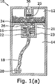
図1(a)に示すように、ガス発生装置は、第1の反応物を具備する反応室部12と、第2の反応物を具備する貯蔵部14と、自己調整流れ制御装置16と、配管18とを含んでよい。代替的には、反応室部12が反応物の代わりに触媒を含んでよく、また反応室部12が加熱されてよい。配管18は、貯蔵部14に配置された第1の端部と、反対側の第2の端部とを含み、第2の端部が反応室部12に対して取り外し可能に結合でき、または動作可能に関連づけできるようになっている。第1の反応物および第2の反応物が一緒に混合されると、反応して水素ガスを生成する。
As shown in FIG. 1 (a), the gas generator includes a
貯蔵部14内に部分的な真空が形成されないように、拡張物質を貯蔵部14に挿入して、反応物が搬送されているときに、拡張物質が少なくとも部分的に搬送済みの体積を置き換えるようにしてよい。適切な拡張物質は、これに限定されないが、ブタン、メタノールのようなアルコール、加圧されているバルーン、その他を含む。代替的には、開放バルブを貯蔵部14と連通させて配置して、反応物が貯蔵部14から搬出されるときに空気を流入させるようにしてよい。部分的な真空を最小化する他の装置は以下で検討される。これら装置はこの発明のいずれの実施例とともに採用してよい。
In order to prevent a partial vacuum in the
ガス発生装置10は、配向装置、例えば、おもり20を具備しても良く、このおもり20は配管18の一部に結合されて、配管18の第1の端部が貯蔵部14内の第2の反応物と確実に流体連通するようになす。おもり20は、装置10の向きに関わらず、配管20の第1の端部を、第2の反応物が累積して配置されている位置に移動させることが可能な任意の重量を有してよい。したがって、反応物が貯蔵部14から引き抜かれるときに、液体反応物のレベルが貯蔵部14内で減少し、装置10がどのような位置、例えば、横方向、斜め方向、上下方向にあっても、それと無関係に、配管18の第1の端部が第2の反応物に接触しなければならない。換言すれば、おもり20および残留燃料が同一の方向に重力により引かれ、このため接触を維持する。配管18の第2の端部は、好ましくは図示のとおり、それが反応室部12に入れられる前に拡張され、より効率よく第2の反応物を分配する。
The
配管18は、貯蔵部12内の第2の反応物を反応室部12へ搬送することが可能な任意の材料から製造できる。このましくは、配管18は、液体を芯材で吸い上げることができる、すなわち、毛細管現象を実現する任意の材料またはデザインを含んでよい。適切な配管材料は、これに限定されないが、ファイバー、フィラー、繊維材料、オープンセル発泡体、砂材料、またはこれらの組み合わせを含む。好ましくは、配管18は柔らかい。配管18は、第2の反応物を反応室部12へ搬送可能な任意の形状を採用できる。配管18は非透過性の鞘または固体ブロック中に埋め込まれた1または複数の芯材部材を有してもよい。
The
貯蔵部14からの第2の反応物が反応室部12へと、重力による供給により、配管18を伴うことなしに、案内可能な位置または向きでガス発生装置10が主に使用されるならば、当該ガス発生装置10はオプションとして配管18を含まない。
If the
ガス発生装置10は反応室部12および貯蔵部14の間に層4をも含んでよい。層24は多孔性面を具備し、第2の反応物を第1の反応物へと均一に分配/案内することが可能な任意の材料から製造できる。層24は好ましくは配管18と類似の芯材材料である。
The
さらに、バス発生装置10は、オプションとして、液体非透過性、ガス透過性の層/膜25を含んで良く、これが水素ガスのようなガスを装置の外部へ案内でき、同時に液体を反応室部12内に維持できる。膜25は、当業者に既知の任意の液体非透過性/気体透過性材料から製造できる。そのような材料は、これに限定されないが、アルカン基を有する撥水性材料であってよい。より具体的な例は、これに限定されないが、ポリエチレン組成物、ポリテトラフルオロエチレン、ポリプロピレン、ポリグラクチン(VICRY、商標)、冷凍乾燥硬膜、またはその組み合わせを含む。気体透過性部材22は、多孔性部材を被覆する気体透過性/液体非透過性膜を含んでよい。このような膜の例はCELGARD(商標)およびGORE−TEX(商標)である。この発明に採用できる、他の気体透過性、液体非透過性部材は、これに限定されないが、約0.1μm〜約0.45μmの孔サイズのSURBENT(総評)ポリビニリデンフロライド(PVDF)を含み、これはMillipore社から入手できる。SURBENT(商標)PVDFの孔サイズはシステムを出る水および/またはメタノールの料を調整する。0.2μmのハイドロを具備する電子ベントタイプ材料のような材料もこの発明に使用でき、これはW.L.Goreから入手できる。さらに、GenPore社から入手できる。孔サイズが約10μmの直径が0.25インチの棒、厚さが約0.3μmの直径2インチのディスク、およびApplied Porous Technologies社から入手できる、孔サイズが約10μm未満の焼結および/またはセラミックの多孔性材料も、この発明医利用できる。さらにBell Labs社からのナノガラス材料も液体をフィルタリングするのにしようできる。ナノガラスは、特別に加工したガラスのブレードに類似するシリコン表面に電荷を与えて、小さな液体滴の振る舞いを制御する。さらに、または代替的には、米国特許出願10/356,793に開示されている気体透過性、液体非透過性材料もこの発明に使用でき、その内容は参照してここに組み入れる。
Furthermore, the
バルブ36は好ましくは遮断バルブであり、開となって、生成されたガスを所望の位置、例えば燃料電池へ搬送することができる任意のバルブであってよい。バルブ36は水素ガスが必要なときに開にされ、水素ガスの需要がないときに閉にされる。バルブ36はユーザにより手作業で制御されても、必要であれば、CPUまたは制御装置により自動的に制御されてもよい。バルブ36は逆止めバルブ、カモノハシバルブ、ソレノイドバルブ、磁気バルブ、その他の機械バルブ、および/または電気バルブであってよい。この発明において使用して適切な遮断バルブはさらに本出願人に係る2004年11月1日出願の米国特許出願10/978,949および同じく2003年7月29日出願の米国特許出願10/629,006に開示されている遮断バルブを含む。これらの内容は参照してここに組み入れる。代替的には、バルブ36は開を維持して良く、燃料電池または装置内の他のバルブが水素の流れを制御するために開および閉されてよい。
The
この実施例では、配管18の拡張された第2の端部が自己調整流れ制御装置16と動作可能に関連づけられる。流れ制御装置16を除いて、反応室部12および貯蔵部14は相互に仕切り部23により隔離されている。図1(a)に示すように、流れ制御部16は、バネ22によりバイアスされたディスク26を含む。ディスク26およびバネ22の双方は、区切り部23により包囲されている。ディスク26は区切り部23に対して可動であり、その間にシールを形成する。シール21、例えばO−リングは、図示のとおり、ディスク26に一体に組み込み可能であり、シールを形成する。好ましくは、ディスク26は、少なくとも、実質的に非透過性の面を含み、この面が配管18の拡大した第2の端部を支持し、あるいは、ディスク26が実質的に非透過性の材料から製造して良い。
In this embodiment, the expanded second end of
動作状態すなわち流れている状態では、配管18の拡大した第2の端部が芯材層24に連結され、あるいは、接触して、流路を形成し、第2の反応物が貯蔵部14から芯材動作(wicking)または毛細管減少により反応室部12に搬送されて反応し水素ガスを生成する。ガスが生成されると、反応室部12の内部の圧力が増大する。ディスク26は実質的にガスに対して非透過性であり、配管18も、第2の反応物により湿潤されているときには、気体が配管18を下降していくのを阻止することが可能であるので、増大したガスの圧力がバイアスバネ22に抗してディスクに力を加える。さらに、シール21は、水素ガスがディスク26の回りを通り、および/または、漏れるのを阻止する。したがって、バルブ36が閉の時のガスの圧力が可能のディスク26に作用する。予め定められた圧力以上で、反応室部12内のガス圧力がディスク26および配管18の拡大された第2の端部を、図1(b)に示すように、芯材層24から離して空間37を形成する。配管18が芯材層24から離れると、毛細管減少の流路が遮断されて、第2の反応物の搬送が停止される。
In an operating state, that is, in a flowing state, the enlarged second end of the
水素ガスが必要なときには、バルブ36が手作業、電子的、または自動的に開とされて、反応室部12内のガス圧力が開放される。反応室部12内の圧力が減少して予め定められた圧力を下回ると、バネ22がディスク26を押して配管18の拡大した第2の端部が芯材層24と接触して第2の反応物の反応室部12への流れが再開され、水素の発生も再開される。水素ガスがもはや必要でなくなると、バルブ36が閉じられ、反応室部12の内部の圧力が増大して予め定められた圧力に到達し、これにより、増大した圧力が、配管18の拡大した第2の端部をディスク24から離して、第2の反応物の反応室部への流れが停止され、水素の生成が停止する。
When hydrogen gas is required, the
このように、流れ制御装置16は自己調整的であり、動作状態すなわちON位置では、配管18の第1の端部がバネバイアスされて反応室部12と接触して第2の反応物を芯材作用または毛細管減少により反応室部へ搬送する。非動作状態すなわちOFF位置では、予め定められた圧力を越える反応室部12内の圧力が配管18を反応室部12から分離して第2の反応物の反応室部12への流れを停止し、水素の生成を停止する。
Thus, the
貯蔵部14内に部分的な圧力が形成されるのを最小化するために、さらに、上述の排気装置に加えて、バッフル140を配管18の回りに設けて良く、このバッフル140は反応室部12からの水素ガスを貯蔵部14へ案内する排気機構である。事例的な適切な排気機構は、本出願人に係る、筆記用具に関する米国特許第5,906,446号に十分に説明されている。’446特許は、空気をインク貯蔵部に流入させて真空の形成を最小化し、これと同時にインクが当該排気機構を介して流れ出ないようにする、排気機構を教示している。’446特許の内容は参照してここに組み入れる。
In order to minimize the formation of partial pressure in the
’446特許の図面に示し、また図11として部分的に再現するように、バッフル140は芯材要素を包囲し、複数のリブ142、144、146、148等を有する。これらリブの間の間隔は、反応室部12から貯蔵部14へ向かって減少する。より具体的には、反応室部12のより近くに位置するリブ142は、つぎの組のリブ144より相対的に大きな間隔を有し、リブ144はリブ146より相対的に大きな間隔を有し、以下同様である。リブの組の数はいくつでもよく、この発明はリブの組のどのような個数にも限定されない。
The
この構成によれば、予め定められたレベルの部分的な真空が貯蔵部14内にあるときには、水素は反応室部12から貯蔵部14へ連絡できるけれども、反応物は貯蔵部14から反応室部へ流れることができない。先に検討したように、反応物の流れは配管18を通じて制御され、これは図示のとおり2以上の異なる芯材材料を有してよい。
According to this configuration, when a predetermined level of partial vacuum is in the
代替的な自己調整流れ制御装置16は図1(c)および1(d)に示される。この自己調整流れ制御装置はハウジング32を具備し、これが、バネ28によりバイアスされた可動部材30を含む。ハウジング32は、一端で、反応室部12に圧力入力ポート34によって結合され反応室部12内の圧力が入力チャンネル34を介して連通してバイアス力に抗して可動部材30に作用する。
An alternative self-regulating
図1(c)および1(d)に示し、19で参照されるように、可動部材30は好ましくは配管18の一部を含む。反応室部12内の圧力が予め定められた圧力より小さいときには、バネ28が、部材30を押して少なくとも部分的に整合させて少なくとも部分的に流路が形成される寸法および形状をとる。このため、動作状態すなわちON位置では、バネ28の力が少なくとも部分的にセクション19を配管18と整合させて連続した毛細管の流れを配管18の第1の端部と配管10の拡大した第2の端部との間に形成する。貯蔵部14の第2の反応物は配管18の第1の端部から配管18の第2の端部へと流れ、さらに反応室部12へと流れることができ、反応して水素を生成する。
As shown in FIGS. 1 (c) and 1 (d) and referenced 19, the
反応室部12内の圧力が予め定められた値を越えると、図1(c)に示すように、圧力がポート34を介して可動部材30に伝わり、部材30をバネ28に抗して変位させて、セクション19がもはや配管18と整合しなくなる。したがって、非動作状態、すなわちOFF位置では、このような非整合状態となり、このため第2の反応物の反応室部12への流れが停止する。図1(a)および1(b)で示す実施例と同様に、バルブ36が開になると、反応室部12内の圧力が減少する。圧力が開放され、バネ28が部材30内のセクション19を移動させて配管18と少なくとも部分的に整合させて、第2の反応物の反応室部12への流れを再開できる。オプションのシールを、OFF位置で配管18をセクション19から分離するために可動部材30との間に設け、または配管18とバネ28との間に設け、または、配管18と圧力ポート34との間に設けて良い。
When the pressure in the
図1(a)および1(b)に示すように、第1の反応物は固体として示される。しかしながら、第1の反応物は水性でも液体形態でもよい。添加物、例えば、安定剤、触媒、または他の添加物が第1の反応物またな第2の反応物、あるいは双方と混合され、あるいはブレンドされてよい。固体の反応物は、これに限定されないが、粉末、ペレット、多孔質構造、球、チューブ、溶解性シートまたはこれらの組み合わせを含む。この発明は、個々の燃料、または添加物、または添加物をどのように混合しブレンドするか、バス発生装置中にどのように貯蔵するかに制約されない。 As shown in FIGS. 1 (a) and 1 (b), the first reactant is shown as a solid. However, the first reactant may be aqueous or liquid form. Additives such as stabilizers, catalysts, or other additives may be mixed or blended with the first reactant or the second reactant, or both. Solid reactants include, but are not limited to, powders, pellets, porous structures, spheres, tubes, soluble sheets or combinations thereof. The invention is not limited to how individual fuels, or additives, or additives are mixed and blended, or stored in a bus generator.
図2に示される他の実施例では、ガス発生装置40は自己調整流れ制御装置16を含み、これが自己調整ガス圧調整装置42またはガスバルブ42と、自己調整液体制御同値41または液体バルブ41とを具備する。流れ制御装置16は貯蔵部14を反応室部12に連結する。貯蔵部14は第2の反応物を保持するブラダーまたはライナー44を含んでよい。ブラダー44は可撓性の材料または弾性材料を含む任意の材牢から製造できる。適切なブラダーは、本出願人に係る米国特許出願10/629004に開示されており、その内容は参照してここに組み入れる。代替的にはブラダー44に代えて、貯蔵部14は、第2の反応物から圧力を隔離することができる任意の部材、例えば、貯蔵部14との間でシールを形成する可動壁、圧縮ガスを収容するようになされた拡張可能ライナーを具備してよい。上述した実施例と同様に、反応室部12は芯材層46(芯材層26と類似する)を具備して反応室部12内の第2の反応物の分配を改善してよい。反応室部12は、芯材材料または液体非透過性、気体透過性膜(膜25に類似する)から製造されるフィラーディスク48を具備して別個の気体収集室部50を形成してよい。バルブ36が設けられて、水素ガスを室部50または反応室部50から燃料電池へ搬送する。ディスク48は、類似の材料から製造されるオプションのロッド47に結合されて良く、これにより、第2の反応物を第1ン反応物のカラムを通じて支持し分配する。図2(b)−2(d)に示すように、第1の反応物はペレットの形態をしている必要はないけれども、ジグザグ形状のウェファ、線形のウェファ、またはグリッド形状のウェファにそれぞれなされてよい。だらに、ガス発生装置40は、図2(b)−2(d)に示すように、スプレイアタッチメント39を含んでよく、第2の反応物を第1の反応物ウェファ状に均一に分散する。
In another embodiment shown in FIG. 2, the
自己調整流れ制御装置16は、第2の反応物が所定の条件の下で反応室部12に入るのを可能にする。好ましくは、自己制御流れ制御装置16は、第2の反応物を内包するブラダー44を第1の反応物を内包する反応室部12へ結合する気体バルブ42および液体バルブ41を有する。当初、ガス発生装置40が構築された後、貯蔵部14が加圧されてわずかな量の第2の反応物が反応室部12に搬送されて反応が開始されて水素ガスを生成する。反応室部12の内部の圧力が増加して、それが貯蔵部14内の圧力と等しくなる。これら2つの区画の圧力が予め定められた差分、例えばX psi(=X×6.895kPa)の範囲内になると、気体バルブ42が開となってこれら2つの区画内の圧力を等しくする。これら2つの圧力が実質的に等しくなると、例えば相互にX psi(=X×6.895kPa)以内になると、ブラダー44に印可する圧力が液体バルブ41を開にできなくなり、第2の反応物の流れが生じなくなる。したがって、ガス発生装置40は、反応室部12が加圧されるときに非動作状態すなわちOFF位置になる。一例では、X psi(=X×6.895kPa)は約1psi(6.895kPa)から約20psi(137.9kPa)の予め定められた値であり、好ましくは、Xは5psi(34.48kPa)でよく、より好ましくは、Xは約2psi(13.79kPa)でよい。
Self-regulating
水素が必要なとき、遮断バルブ36が開となり、ガス発生装置40が動作すなわちON位置になる。水素がガス収集室部50または反応室部12から搬送されると、反応室部12内の圧力が減少する。貯蔵部14および反応室部12の間の圧力差がX psi(=X×6.895kPa)を超えると、気体バルブ42が閉となり、これにより、貯蔵部14をより高い圧力に維持する。貯蔵部14内の維持圧力がブラダー44に加わり、これが液体バルブ41を開いて第2の反応物を反応室部12に搬送して第1の反応物と反応する。
When hydrogen is required, the
高く維持された貯蔵部14内の圧力が抽気されると、2つの室部の圧力が再びX psi(=X×6.895kPa)内になる。反応室部12内の生成ガスが、反応室部12からの圧力が貯蔵部14内の圧力と等価になるまで、気体バルブ42を開とし、液体バルブ41を閉として第2の反応物の流れを停止させて反応を停止させる。水素ガスを生成する反応を継続させるために、処断バルブ36が閉じられる。好ましくは、貯蔵部14内の高く維持された圧力がすべて抽気される前に、双方の圧力がお互いにX psi(=X×6.895kPa)である間に、閉じられる。このように閉じると、室部12および貯蔵部14の双方が再加圧される(気体バルブ41が開のままであるので)。圧力が所望のレベルに至ると、バルブ36が再び開とされてサイクルを再開する。バルブ36の開および閉動作は循環的であり、CPUまたはコントローラにより制御できる。圧力ゲージをガス発生装置40内に挿入でき、CPU/コントローラが読み出し可能であり、これにより開/閉サイクルを制御する。ガス発生装置40の事例的な動作サイクルは、以下にまとめられる。
When the pressure in the
代替的には、遮断バルブ36を循環させることなしに水素の生成を維持するために、貯蔵部14内のブラダー44を連続的に例えば圧力ガスにより加圧して良い。好ましくは、貯蔵部14は十分な量の液化炭化水素、例えば、N−ブタン、イソブタン、またはイソブタンおよびプロパンのブレンドを具備する。これらの材料の気液図は、炭化水素のうちのいくらかが液体形態のままである限り、その圧力が一定になるというものである。一例において、貯蔵部14内の圧力は17psi(117.2kPa)に維持され(N−ブタンを室温で使用)、反応室部12内の圧力が17psi(117.2kPa)からX psi(=X×6.895kPa)の範囲内またはそれ以上のときに、気体バルブ42が開となり、圧力を等価とし、液体バルブ41を開とする当該バルブ41を横切る顕著な圧力差がなく、そのため、流れが生じない。水素ガスが必要なときには、バルブ36を開にして、2つの室部の間の圧力差がX psi(=X×6.895kPa)より大きくなり、気体バルブ42が閉となる。そして、貯蔵部14内の圧力がブラダー44に加わり、液体バルブ41を開として第2の反応物を反応室部12へと搬送する。これはバルブ36が閉となるまで継続する。貯蔵部14内の加圧ガスが反応室部12に入り込むのを最小化、または阻止するために、気体バルブ42は一方向でよく、すなわち、水素ガスの反応室部12から貯蔵部14への搬入のみを許容する。また、貯蔵部14が加圧されるときに、気体バルブ42を省略して良く、貯蔵部14および反応室部12の間の変化する圧力差が十分に大きく液体バルブ41を開および閉にすることができる。この実施例はさらに図5(a)を参照して以下に説明する。また、多孔質膜を気体バルブ42の近傍に配置して良い。適切な多孔性膜は、より小さな水素分子は透過させるほど大きく、より大きな炭化水素分子は阻止するほど小さいサイズでなければならない。
Alternatively, the
代替的には、イソブタンまたはイソブタン/プロパンのブレンドをN−ブタンに変えて採用して良く、その圧力はそれぞれ約31psi(213.7kPa)および50psi(344.8kPa)である。X psi(=X×6.895kPa)は任意の圧力で良く、例えば、2psi(13.79kPa)、4psi(27.58kPa)、6psi(41.37kPa)等である。 Alternatively, isobutane or isobutane / propane blends may be substituted for N-butane, the pressures of which are about 31 psi (213.7 kPa) and 50 psi (344.8 kPa) , respectively. X psi (= X × 6.895 kPa) may be any pressure, such as 2 psi (13.79 kPa) , 4 psi (27.58 kPa) , 6 psi (41.37 kPa) , and the like.
他の動作モードにおいて、反応室部12内の水素発生速度は遮断バルブ36から出る寿司その速度より大きい。このため、バルブ36が開位置にあるときに、反応室部12の内部の圧力が、貯蔵部14内の圧力より大きな圧力へと増大し続ける。反応室部12内の圧力が予め定められた値だけ貯蔵部14の内部の圧力を越えると、液体バルブ41が閉となり第2の反応物が反応室部12に搬入されるのを阻止し、気体バルブ42が開となり反応室部12の内部の圧力が少なくとも貯蔵部14の内部の圧力と実質的に等しくなるようにできる。水素の需要が継続する場合、反応室部12の内部の圧力は減少して貯蔵部14内の圧力より小さな圧力となり、この結果、気体バルブ42が閉となり、液体バルブ41が開となる。この動作モードの要約を以下の表2に示す。

実際、ガス発生装置40は、比較的新しいとき、すなわち、装置が新しく、反応速度が比較的大きいときには、表2に示される動作モードによって動作可能である。反応物が枯渇に近づき、反応速度が所定速度をしたまわると、ガス発生装置40は表1で示される動作循環で動作してよい。
In fact, when the
ガス発生装置40はさらに開放バルブ43を含んでよい。開放バルブ43の目的は、反応室部12内に過剰な圧力が形成されるのを阻止することである。例えば、開放バルブ43は、反応室部12内の圧力が予め定められた値に達すると開となることができるバルブである。好ましくは、開放バルブ43は逆止めバルブである。代替的には、開放バルブ43は手作業で開にでき、水素貯蔵領域50内のいくらかの水素を排出する。膜25は開放バルブ43とともに採用して液体が装置40から流出するのを阻止してよい。
The
図3に示すように、オプションのスタータ52をガス発生装置40内に含んで良い。スタータ52は初期圧力をブラダー44に加えて第2の反応物を反応室部12へ案内させて反応を開始させることができる。スタータ52は当業者に既知の任意のタイプのスタータであってよい。これは手動のスタートでもよく、ガス発生装置が生成ガスを必要とする機器に結合されると初期反応を開始できる自動スタータであってもよい。例えば、スタータ52は、圧縮、移動、回転させて直接または間接的に圧力をブラダー44に加えて第2の反応物の少なくとも幾分かを反応室部に案内することができるボタン、ポンプ機構、スライド機構、および/またはネジであってよい。事例的なスタータは図8(a)−8(d)に示される。
An
図4(a)を参照すると、自己調整流れ制御装置16は隔膜56を有してよく、これがブラダー44の開口54を被覆して第2の反応物の流れを阻止し、また開口54を被覆解除して第2の反応物の反応室部12への流れを許容するように構成される。隔膜56は、貯蔵部14および反応室部12の間の圧力差に応答する。図示のとおり、貯蔵部14が、圧縮ガス、バネ、発泡体、液化炭化水素、または他の圧力機構により加圧されて実質的に一定の圧力をブラダー44に加える。当初、最初の使用の前では、貯蔵部14内の大きな圧力により、第2の反応物の幾分かが開口54および隔膜56の孔55を通じて搬送されて第1の反応物と反応する。生成された水素が、反応室部12内の圧力が貯蔵部14の圧力からX psi(=X×6.895kPa)の範囲になるまで、反応室部12を加圧する。隔膜56は、X psi(=X×6.895kPa)の範囲内では、図4(c)に示すように、開口54を閉じ、第2の反応物の流れを停止するような寸法および形状とされる。水素ガスが必要なときには、遮断バルブ36が開にされ、反応室部12内の圧力が減少する。隔膜56は図4(b)に示すように開となり、この結果、第2の反応物が反応室部12へ流れて必要な水素を生成する。水素がもはや必要でないときには、バルブ36は遮断され、反応室部12が再加圧されて流れを停止する。
Referring to FIG. 4 (a), the self-regulating
図5(a)を参照すると、隔膜56が逆止めバルブ57に置き換えられて良く、これが隔膜56と同一の条件で開および閉となる。図5(b)は流れ調整器58を示す。好ましくは、調整器58は第2の反応物を吸収可能なフィラー材料から製造される。そのため、第2の反応物を吸収可能な任意の材料をこの発明に採用できる。適切な材料は発泡体、フィラーまたは繊維材料である。他のオプションは、これに限定されないが、復帰バルブおよび噴霧制限である。
Referring to FIG. 5 (a), the
図6の示すように、ガス発生装置40は、バルブ65および可動部材すなわちピストン68に連結されたスタータ64を含んで良い。スタータ64を押してバルブ65を開にして第2の反応物を反応室部12へ案内して反応を開始できる。スタータ64は手動のスタートでもよく、ガス発生装置が生成ガスを必要とする機器に結合されると初期反応を開始できる自動スタータであってもよい。可動部材68はオプションとしてバルブ69を含んでも良い。オプションのバルブ69をこの発明で使用すると、スタータ64を、初期反応を開始するのに使用できる。初期反応が開始されて反応室部12が加圧されると、この圧力が、オプションのバルブ69を開として第2の反応物の反応室部12への流れを可能にする傾向があるピストン68に加わる。
As shown in FIG. 6, the
可動部材68およびガス発生装置40の壁部の間にシールを形成するために、また第2の反応物を第1の反応物と隔離するために、可動部材68は1またはそれ以上のシール62、例えばo−リングを有してよい。さらに、可動部材68およびガス発生装置40の壁部の間の摩擦を補償するために、オプションの(1または複数の)バネ66を図6に示すように反応室部12中に配置して良い。
In order to form a seal between the
反応が開始すると、反応室部12内の圧力が予め定められたレベルへと増大して、反応室部12内の圧力がバルブ69を閉にして第2の反応物の反応室部12へ至る流れを停止する。貯蔵部14内に真空が生成されるのを最小化するために、また第2の反応物へ圧力を加え、および/または維持するために、可動部材68がバネ66によって貯蔵部14へとバイアスされる。バルブ36を開にすることにより反応室部12内の圧力が減少されたのち、貯蔵部14内のより大きな圧力がバルブ69を開にしてさらに第2の反応物を反応室部12へ搬送してさらに水素を生成させる。代替的には、オプションのバルブ69を可能部材68に組みこまないときに、必要時に、スタータ64が押圧されてバルブ65を開にして第2の反応物の反応室部12への流れを開始させてよい。
When the reaction starts, the pressure in the
他の実施例が図7に示される。この実施例は図6と類似である。ただし、バネ66が貯蔵部14内に配置され、可動部材68がバルブ69を含んでいない。さらに、スタータ64は、軸71に置換され、これが、バルブすなわち末端17を具備し、これが回転可能である。軸71が回転動作するとバルブも比例して回転し、これにより、第2の反応物の反応室部12への流れが開始および停止される。図7に示すような、バルブシステムは一般に産業界では「線形制御バルブ」(linear control valve)または「グローブバルブ」(globe valve)として知られている。そして、初期の反応を開始するために、軸71を回転させてバルブ17を開にする。この実施例における水素発生プロセスは図6に関連して検討したプロセスと類似である。ただし、この実施例では、部材68が貯蔵部14へ移動するとき、部材68の移動が軸71と連結されたバルブ17を回転させて第2の反応物の反応室部への流れを停止させる。反応室部12内の圧力が予め定められた圧力を下回るとき、バネ66が可動部材68を反応室部12へと押して、この結果、これが、軸71に結合されているバルブ17を回転させて開となす。
Another embodiment is shown in FIG. This embodiment is similar to FIG. However, the
図8(a)はこの発明の他の実施例を示す。このガス発生装置においては、反応室部12が貯蔵部14/ブラダー44から可動ピストン68によって隔離されている。ただし、反応室部12は、ピストン68に形成された開口78を通じてt貯蔵部14に対して一定の流体連通となっている。可動ピストン68は、また、反応室部12内に配置されたバネ66によって貯蔵部14へとバイアスされている。反応を開始するためには、スタータ74を作動させ、例えば、押圧する。スタータ74の作動により圧力が生成されると、逆止めバルブを開にして第2の反応物を反応室部12へ開放して第1の反応室部と反応させる。水素ガスが生成され、ガス発生装置全体を加圧する。バルブ36が開となると、水素ガスが開放される。貯蔵部14および反応室部12の間の圧力差がないので、何も第2の反応物の反応室部12への流れを阻止しない。このため、水素が、反応物が消費されるまで生成される。
FIG. 8A shows another embodiment of the present invention. In this gas generator, the
図8(b)−8(d)は他のタイプのスタータを示す。図8(b)に示すように、押しボタン74がポンプボタン82に置き換えられて良く、これが、ガス、例えば空気をブラダー78に満たす。ブラダー78はブラダー44に力を加えて第2の反応物の少なくとも幾分か、または予め定められた量を反応室部12に案内できる。さらに、図8(c)に示すように、押しボタン74をネジ式の装置76で置き換えることができ、これを回してブラダー44に力を加えることができる。他のオプションの実施例は、図8(d)に示すように、スライド機構82を含んでよい。この実施例では、スライドスイッチ82が予め定められた方向に移動されるときに、ブラダー44に力が加えられ、第2の反応物の幾分か、または予め定められた量が反応室部12へ開放される。
8 (b) -8 (d) show another type of starter. As shown in FIG. 8 (b), the push button 74 may be replaced by a
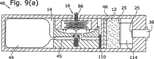
この発明の他の実施例が図9(a)−9(d)に示される。このガス発生装置は、第2の反応物を具備する貯蔵部14に結合され、第1の反応物を具備する反応室部12を含む。貯蔵部14およびブラダー44は制御装置16に取り外し可能に連結できる。貯蔵部14が制御装置16に取り外し可能に結合されるときに、好ましくはブラダー44が逆止めバルブを具備してブラダーをシールし、配管45が対応する逆止めバルブを具備し配管をシールしブラダー上の逆止めバルブと係合してその間の流路を形成する。適切な対応するバルブは米国特許出願10/624006および同10/978949に十分に開示されており、その内容は参照してここに組み入れる。また、好ましくは、リョ増部14は上述のとおり、好ましくは液化炭化水素により、加圧される。
Another embodiment of the present invention is shown in FIGS. 9 (a) -9 (d). This gas generator is coupled to a
自己調整流れ制御装置16は配管45/隔膜92を有し、これが棒94と相互作用し、また動作可能に関係付けられる。棒94は配管45内に配される。非動作すなわちOFF位置では、図9(c)に示すように、棒94がシール面97に愛してシール98を有して流れを阻止する。図示のとおり、配管45は数ターンしている。ただし、流路の実際の形状は重要でなく、この発明は配管45のいかなる具体的な形状にも制約されない。好ましくは、シール98は、ずれ要素(shear component)なしに圧縮されてシール98の寿命を伸ばす。これは角度のないシール面、例えばシール面97により実現できる。動作すなわちON位置では、図9(d)に最も良く示すように、棒94およびシール98がシール面97から離れて流れを可能にする。シール98はo−リング、ワイパー、または他の任意のシール要素を含む。
Self-regulating
隔膜92および棒94はオプションの上側バネ88および下側バネ96の間で平衡状態にされている。こられバネは予め荷重を受けており、反応室部12の予め定められた圧力に対応しており、ガス発生装置はこの圧力を越えると閉じる。オプションの調整部86を設けてバネの相対的な荷重を調整する。図9(b)に最もよく示すように、反応室部からの圧力P2が配管45に戻される(液体の第2の反応物または生成された水素を通じて流体的に)。圧力P2は隔膜92の底に作用し、P2が十分に大きいときに、P2が隔膜92および棒94を上方に押して配管45の流路を閉とする。バネ88および96の予めの荷重、またはこれらバネの間の相対的な予めの荷重が圧力を決定し、配管45が遮断される前にP2がこの圧力に達する。代替的には、バネ88および96のうちの1つを省略してよい。例えば、バネ96を省略して、バネ88を残し、これが隔膜92に作用する圧力P2と平衡するようになしてよい。
The
他の実施例と同様に、反応室部12はバルブ36、これを被覆する少なくとも1つの液体非透過性、気体透過性の膜25を具備する。反応室部12は、少なくとも1つのフィラー/フィルタ46と、隔膜92の領域に入る粒子を阻止し、少なくともその数を減少させる、少なくとも1つのスクリーンと、ガス発生装置の目詰まりを最小化する少なくとも1つの拡散メッシュ114と、スクリーン110の閉塞を阻止する少なくとも1つの拡散メッシュ120とを有する。オプションとして、ガス発生装置40は、ブラダー44およびシール98の間に気体非透過性部材を含んでいずれのガスもブラダー44に入らないようにしてよい。
Similar to the other embodiments, the
他の実施例を図10に示す。この実施例では、ガス発生装置40は、貯蔵部14および反応室部12に加えて、室部126を含む。室部126は可動部材68によって反応室部12から分離されており、この可動部材68がバルブ要素132および128を配置させている。好ましくは、気体透過性/液体非透過性部材48がバルブ要素132および128の間に配置されて、任意の生成ガスが反応室部12から排出されるときに、反応室部12に液体を保持するようになっている。室部126はさらに雄バルブ130を有し、これが雌バルブ128と結合するようになっている。
Another embodiment is shown in FIG. In this embodiment, the
可動部材68は遮断バルブ36および貯蔵部14の間を往復動する。一側では、可動部材68はバネ66によりバイアスされ、他側では、反応室部12内で生成されたバスにより押圧可能である。可動部材68が遮断バルブ36へと押圧されるとき、バルブ130はバルブ128と連結してガスを反応室部12からガス室部132へと搬送する。可動部材68が貯蔵部14へと押圧されるときに、バルブ134がバルブ132と結合して第2の反応物をさらに貯蔵部14から反応室部12へと搬送する。
The
好ましくは、初めての使用に先立って、反応室部12は、加圧ガス、例えば、不活性ガス、空気または水素を含む。ガスは、雌バルブ128を雄バルブ130に適切に接触させる距離だけ可動部材68を押圧する予め定められた圧力に近づくレベルへと、反応室部12を加圧する。水素生成が必要なときに、バルブ36は開となり貯蔵されたガスを開放する。この開放により、ガス室部50内の圧力が減少し、反応室部12内の圧力も同様である。反応室部12内の圧力が予め定められたレベルを下回ると、バネ66が可動部材68を貯蔵部14へと押す。好ましくは、バネ66は、雄バルブ132を雌バルブ130中に挿入させるに足る距離、可動部材68を押す。雄バルブ132を雌バルブ134に挿入することにより、経路が開となり、貯蔵部14内の第2の反応物がオリフィス49を介して反応室部12へと流れることができる。第2の反応物が反応室部12に案内されると、これが好ましくは第1の反応物と反応して水素を生成する。圧力が、予め定められた値に達し、すなわちバネ66により可動部材68へ加えられているある圧力を上回ると、可動部材68が雄バルブ130へと押される。雄バルブ130の雌バルブ128との結合により、生成ガスが反応室部12を出て室部50へ至る経路が開となり、この後、バルブ36を介してガス発生装置から排出される。
Preferably, prior to first use, the
このサイクルが、この後繰り返され、可動部材68は、再度、貯蔵具14側へ移動してバルブ134をバルブ132に結合させてさらに第2の反応物を反応室部12へ搬送する。好ましくは、貯蔵部14は加圧され、第2の反応物が先に検討したようにブラダー44内に貯蔵される。
This cycle is repeated thereafter, and the
上述の実施例の各々において、ガス発生装置40は反応室部12および貯蔵部14を含む。いくつかの事例的な実施例では、反応室部12内の第1の反応物および/または貯蔵部14またはブラダー44内の第2の反応物は、オプションとしての触媒、水素担持燃料、および薬剤(例えば水)の少なくとも1つを含んで良く、ここで、薬剤は、触媒を伴って、または伴わずに、第1の水素担持燃料と反応してガスを生成でき、オプションで添加物を含んで良い。好ましくは、薬剤は、触媒の存在下で水素担持燃料と反応して所望のガスを発生させる。好ましくは、反応止痛b12内の第1の反応物と貯蔵部12またはブラダー内の第2の反応物14は同一の組成物でない。さらに好ましくは、水素担持燃料および薬剤は別々の室部に配される。すなわち、反応室部12内の第1の反応物が水素担持燃料であれば、薬剤を貯蔵部14内の第2の反応物として具備することが好ましい。
In each of the above-described embodiments, the
この発明の水素担持燃料は、薬剤/組成物と反応しておよび/または所定の条件下に置かれて、水素を発生させることができる任意の燃料であってよい。いくつかの事例的な実施例では、水素担持燃料は金属水素化物を含んで良い。いくつかの事例的な実施例では、燃料は、これに限定されないが、元素周期表のI−III族の元素の水素化物およびその混合物、例えば、アルカリ性またはアルカリ金属水素化物、またはこれらの混合物を含んで良い。他の化合物、例えばアルカリ金属水素物(アラネート)および水素化ホウ素アルカリ金属も採用して良い。例えば、水素化カルシウムを固体燃料としてこの発明に従ってそのように使用してよい。好ましくは、水素担持燃料はNaBH4を含み、これは固定形態である。好ましくは、液体形態のNaBH4を採用するときには、液体のNaBH4を含む室部が安定剤も含む。例示的な安定剤は、これに限定されないが、金属水酸化物、例えばアルカリ金属水酸化物を含んで良い。最も好ましい安定剤は、NaOHである。 The hydrogen-carrying fuel of the present invention may be any fuel that can react with the drug / composition and / or be subjected to predetermined conditions to generate hydrogen. In some example embodiments, the hydrogen-supported fuel may include a metal hydride. In some exemplary embodiments, the fuel includes, but is not limited to, a hydride of a Group I-III element of the Periodic Table of Elements and mixtures thereof, such as alkaline or alkali metal hydrides, or mixtures thereof. May include. Other compounds such as alkali metal hydrides (alanate) and alkali metal borohydrides may also be employed. For example, calcium hydride may be used as such in accordance with the present invention as a solid fuel. Preferably, hydrogen-bearing fuel comprises NaBH 4, which is a fixed form. Preferably, when liquid form NaBH 4 is employed, the chamber containing liquid NaBH 4 also contains a stabilizer. Exemplary stabilizers may include, but are not limited to, metal hydroxides, such as alkali metal hydroxides. The most preferred stabilizer is NaOH.
いくつかの事例的な実施例において、第1の反応物、第2の反応物、または双方は、燃料源の反応速度を増大させることにより水素の発生を容易にする触媒を含んでよい。この発明の触媒は、所望の反応を支援できるいかなる形状またはサイズを含んでよい。例えば、触媒は粉末の形態をとるほど小さくて良く、また、貯蔵部または反応室部と同じくらいに大きくて良い。いくつかの事例的な実施例では、触媒は触媒床である。この触媒は、第1の反応物または第2の反応物の少なくとも一方が触媒に接するようになる限り、反応室部の内部、貯蔵部の内部またはブラダーの内部、反応室部、貯蔵部、またはブラダーの近傍にあってよい。 In some example embodiments, the first reactant, the second reactant, or both may include a catalyst that facilitates hydrogen generation by increasing the reaction rate of the fuel source. The catalyst of this invention may comprise any shape or size that can support the desired reaction. For example, the catalyst may be small enough to take the form of a powder and may be as large as the reservoir or reaction chamber. In some example embodiments, the catalyst is a catalyst bed. As long as at least one of the first reactant and the second reactant comes into contact with the catalyst, the catalyst is inside the reaction chamber, inside the reservoir or inside the bladder, reaction chamber, reservoir, or It may be in the vicinity of the bladder.
いくつかの事例的な実施例では、触媒は、ルテニウム触媒、白金触媒、ニッケル触媒、当業者に既知の任意の他の触媒を含んで良い。いくつかの事例的な実施例では、元素の周期律表のVIIIB族からの金属を具備する触媒を採用できる。好ましくは、この発明のバス発生装置とともに採用できる触媒はCoCl2である。 In some example embodiments, the catalyst may include a ruthenium catalyst, a platinum catalyst, a nickel catalyst, or any other catalyst known to those skilled in the art. In some example embodiments, a catalyst comprising a metal from group VIIIB of the periodic table of elements can be employed. Preferably, the catalyst that can be employed in conjunction with the bus generator of the present invention is CoCl 2.
この発明に採用できるいくつかの事例的な燃料は、これに限定されないが、メタノール、水素化ホウ素、アンモニアホウ素、およびヒドラジンを含む。これら事例的な燃料を製造するために、第1の先駆体はジメチルジカーボネート、水、ホウ素含有ポリマー、カーボネート、アンモニア、アジン、および/または過酸化水素であってよい。これらの燃料の各々は米国特許出願10/854540に詳細に説明されており、その内容についてはすでに参照してここに組み入れた。
Some anecdotal fuel that can be employed in this invention include, but are not limited to, methanol, borohydride, ammonia boron, and hydrazine. To produce these exemplary fuels, the first precursor may be dimethyl dicarbonate, water, boron-containing polymer, carbonate, ammonia, azine, and / or hydrogen peroxide. Each of these fuels is described in detail in US patent application Ser. No. 10 / 854,540, the contents of which have already been incorporated herein by reference.
いくつかの事例的な実施例において、燃料と反応可能な薬剤は水である。好ましくは、この発明の第1の反応物は、好ましくは反応室部内に配置され、NaBH4であり、第2の反応物は、好ましくは貯蔵部または貯蔵部内のブラダー内に配置され、水である。 In some example embodiments, the agent capable of reacting with the fuel is water. Preferably, the first reactant of this invention is preferably NaBH 4 located in the reaction chamber and the second reactant is preferably located in a reservoir or a bladder in the reservoir and is is there.
いくつかの事例的な実施例において、オプションの添加物は、反応室部、貯蔵部および/または反応室部18の内部にあってよく、第1の反応物および/または第2の反応物の凝固を実質的に防止できる、すなわちその凝固点を小さくできる任意の組成物であって良い。いくつかの例示的な実施例では、添加物は凍結防止剤であってよい。いくつかの例示的な実施例では、添加物はアルコールベースの組成物である。好ましくは、この発明の添加物はCH3OHである。ただし、上述のとおり、第1の反応物および/または第2の反応物の凝固点を小さくできる任意の添加物を採用できる。
In some exemplary embodiments, the optional additive may be internal to the reaction chamber, reservoir, and / or
液体溶液はオプションとして約3から5のpHの酸を含む。液体溶液に添加される酸の一例は酢酸である。この発明において酸の目的は、液体溶液および固体燃料の間のより定常的な反応を実現するため、および、反応室部の入口において障壁が形成されるのを防止するためである。 The liquid solution optionally contains an acid with a pH of about 3 to 5. An example of an acid added to the liquid solution is acetic acid. The purpose of the acid in this invention is to achieve a more steady reaction between the liquid solution and the solid fuel and to prevent the formation of a barrier at the inlet of the reaction chamber.
上述の明細書およびここで開示された発明の実践を考慮することにより、当業者にはこの発明の他の実施例が明らかであろう。この明細書および例は事例としてのみ考慮すべきであり、この発明の範囲および精神は特許請求の範囲およびその均等物により示されるべきであることに留意されたい。 Other embodiments of the invention will be apparent to those skilled in the art from consideration of the foregoing specification and practice of the invention disclosed herein. It should be noted that the specification and examples should be considered as examples only, and the scope and spirit of the invention should be indicated by the appended claims and their equivalents.
添付図面は明細書の一部を形成し、明細書との関連において理解されるべきであり、種々の図において類似の参照番号は類似の部分を示すために用いられる。添付図面は以下のとおりである。 The accompanying drawings form part of the specification and are to be understood in connection with the specification, wherein like reference numerals are used to indicate like parts in the various views. The attached drawings are as follows.
10 ガス発生装置
12 反応室部
14 貯蔵部
16 自己調整流れ制御装置
18 配管
20 おもり
36 バルブ
DESCRIPTION OF
Claims (16)
第1の反応物であって上記反応室部において反応してガスを生成する上記第1の反応物を有する貯蔵部と、
上記貯蔵部を上記反応室部に結合する流れ制御装置とを有し、
上記第1の反応物が上記貯蔵部から上記反応室部へ上記流れ制御装置を介して搬送されて反応してガスを生成し、かつ、上記反応室部の圧力が予め定められた停止圧力を越えるときに上記流れ制御装置が上記第1の反応物の搬送を停止し、
上記流れ制御装置は、当該流れ制御装置の少なくとも一部を、上記第1の反応物の搬送を可能にする第1の位置、または上記反応物の搬送を阻止する第2の位置へバイアスするバネ部材を有するガス発生装置であって、
さらに上記ガスを開放する遮断バルブを有することを特徴とするガス発生装置。A reaction chamber,
A reservoir having the first reactant which is a first reactant and reacts in the reaction chamber to produce a gas;
A flow control device coupling the reservoir to the reaction chamber,
The first reactant is transported from the reservoir to the reaction chamber via the flow control device to react to generate gas, and the reaction chamber has a predetermined stop pressure. The flow control device stops conveying the first reactant when crossing,
The flow control device includes a spring that biases at least a part of the flow control device to a first position that enables the transfer of the first reactant or a second position that prevents the transfer of the reactant. A gas generator having a member,
The gas generator further comprises a shut-off valve for releasing the gas.
第1の反応物であって上記反応室部において反応してガスを生成する上記第1の反応物を有する貯蔵部と、
上記貯蔵部を上記反応室部に連結する流れ制御装置とを有し、
上記第1の反応物が上記貯蔵部から上記反応室部へ上記流れ制御装置を介して搬送されて反応してガスを生成し、かつ、上記反応室部の圧力が予め定められた停止圧力を越えるときに上記流れ制御装置が上記第1の反応物の搬送を停止し、
上記流れ制御装置は、当該流れ制御装置の少なくとも一部を、上記第1の反応物の搬送を可能にする第1の位置、または上記反応物の搬送を阻止する第2の位置へと移動可能である隔膜を有するガス発生装置であって、
さらに上記ガスを開放する遮断バルブを有することを特徴とするガス発生装置。A reaction chamber,
A reservoir having the first reactant which is a first reactant and reacts in the reaction chamber to produce a gas;
A flow control device connecting the reservoir to the reaction chamber,
The first reactant is transported from the reservoir to the reaction chamber via the flow control device to react to generate gas, and the reaction chamber has a predetermined stop pressure. The flow control device stops conveying the first reactant when crossing,
The flow control device is capable of moving at least a part of the flow control device to a first position that enables transfer of the first reactant or a second position that prevents transfer of the reactant. A gas generator having a diaphragm,
The gas generator further comprises a shut-off valve for releasing the gas.
Applications Claiming Priority (3)
| Application Number | Priority Date | Filing Date | Title |
|---|---|---|---|
| US11/067,167 | 2005-02-25 | ||
| US11/067,167 US7481858B2 (en) | 2005-02-25 | 2005-02-25 | Hydrogen generating fuel cell cartridges |
| PCT/US2006/006182 WO2006093735A2 (en) | 2005-02-25 | 2006-02-22 | Hydrogen generating fuel cell cartridges |
Publications (3)
| Publication Number | Publication Date |
|---|---|
| JP2008531450A JP2008531450A (en) | 2008-08-14 |
| JP2008531450A5 JP2008531450A5 (en) | 2009-03-19 |
| JP5191745B2 true JP5191745B2 (en) | 2013-05-08 |
Family
ID=36930779
Family Applications (1)
| Application Number | Title | Priority Date | Filing Date |
|---|---|---|---|
| JP2007557110A Expired - Fee Related JP5191745B2 (en) | 2005-02-25 | 2006-02-22 | Hydrogen generating fuel cell cartridge |
Country Status (14)
| Country | Link |
|---|---|
| US (5) | US7481858B2 (en) |
| EP (1) | EP1861481A4 (en) |
| JP (1) | JP5191745B2 (en) |
| KR (1) | KR101386444B1 (en) |
| CN (2) | CN105098213B (en) |
| AR (1) | AR053816A1 (en) |
| AU (1) | AU2006218908A1 (en) |
| BR (1) | BRPI0607602A2 (en) |
| CA (1) | CA2597221C (en) |
| MY (1) | MY141634A (en) |
| RU (1) | RU2007134857A (en) |
| TW (1) | TW200635121A (en) |
| WO (1) | WO2006093735A2 (en) |
| ZA (1) | ZA200706718B (en) |
Families Citing this family (93)
| Publication number | Priority date | Publication date | Assignee | Title |
|---|---|---|---|---|
| US9676625B1 (en) | 2011-11-07 | 2017-06-13 | Ardica Technologies, Inc. | Synthesis of microcrystalline alpha alane |
| US10233079B2 (en) | 1999-06-16 | 2019-03-19 | Ardica Technologies, Inc. | Heating methods for aluminum hydride production |
| US10435297B2 (en) | 1999-06-16 | 2019-10-08 | Ardica Technologies, Inc. | Crystallization and stabilization in the synthesis of microcrystalline alpha alane |
| US7556660B2 (en) * | 2003-06-11 | 2009-07-07 | James Kevin Shurtleff | Apparatus and system for promoting a substantially complete reaction of an anhydrous hydride reactant |
| JP5044900B2 (en) * | 2004-06-07 | 2012-10-10 | ソニー株式会社 | Fuel cells, electronic devices, mobile objects, power generation systems, and cogeneration systems |
| EP1793187B1 (en) * | 2004-09-21 | 2011-11-23 | Vives Joan Iglesias | Method and machine for the sintering and/or drying of powder materials using infrared radiation |
| US7803349B1 (en) * | 2005-06-08 | 2010-09-28 | University Of Central Florida Research Foundation, Inc. | Method and apparatus for hydrogen production from water |
| KR101330058B1 (en) * | 2005-06-13 | 2013-11-18 | 소시에떼 비아이씨 | Hydrogen generating fuel cell cartridges |
| US20070036711A1 (en) * | 2005-08-11 | 2007-02-15 | Ardica Technologies Inc. | Hydrogen generator |
| US8795926B2 (en) | 2005-08-11 | 2014-08-05 | Intelligent Energy Limited | Pump assembly for a fuel cell system |
| KR100828704B1 (en) * | 2006-01-24 | 2008-05-09 | 삼성엔지니어링 주식회사 | Thermal siphon reactor and a hydrogen generator having the same |
| US20090004512A1 (en) * | 2006-03-01 | 2009-01-01 | Aquafairy Corporation | Liquid Constant-Rate Emitting Apparatus and Method of Liquid Constant-Rate Emmision |
| US20070271844A1 (en) * | 2006-04-12 | 2007-11-29 | Mohring Richard M | Hydrogen fuel cartridge and methods for hydrogen generation |
| TW200806392A (en) | 2006-06-20 | 2008-02-01 | Lynntech Inc | Microcartridge hydrogen generator |
| US7651542B2 (en) * | 2006-07-27 | 2010-01-26 | Thulite, Inc | System for generating hydrogen from a chemical hydride |
| JP2008091080A (en) * | 2006-09-29 | 2008-04-17 | Casio Comput Co Ltd | Liquid cartridge, power generating device, and electronic apparatus |
| JP5028982B2 (en) * | 2006-12-04 | 2012-09-19 | カシオ計算機株式会社 | Container, power generator and electronic device |
| WO2008097849A2 (en) * | 2007-02-02 | 2008-08-14 | Societe Bic | Hydrogen gas generators |
| US8586261B2 (en) * | 2007-03-26 | 2013-11-19 | Protonex Technology Corporation | Techniques for packaging and utilizing solid hydrogen-producing fuel |
| US20080236032A1 (en) * | 2007-03-26 | 2008-10-02 | Kelly Michael T | Compositions, devices and methods for hydrogen generation |
| US8268028B2 (en) | 2007-03-26 | 2012-09-18 | Protonex Technology Corporation | Compositions, devices and methods for hydrogen generation |
| US20100112396A1 (en) * | 2007-03-30 | 2010-05-06 | Goldstein Avery N | Field hydrogen generation system |
| US8357214B2 (en) | 2007-04-26 | 2013-01-22 | Trulite, Inc. | Apparatus, system, and method for generating a gas from solid reactant pouches |
| DE102007026085B4 (en) * | 2007-06-04 | 2011-11-17 | Fraunhofer-Gesellschaft zur Förderung der angewandten Forschung e.V. | Gas generators, its use and process for producing gases |
| JP4836990B2 (en) * | 2007-06-05 | 2011-12-14 | ローム アンド ハース カンパニー | Hydrogen generating composition |
| JP5064118B2 (en) * | 2007-06-06 | 2012-10-31 | セイコーインスツル株式会社 | Liquid level detection device, fuel cell, liquid level detection method, and liquid level detection program |
| KR101387734B1 (en) * | 2007-07-03 | 2014-04-21 | 삼성에스디아이 주식회사 | Hydrogen generator and fuel cell system with the same |
| JP4280784B2 (en) * | 2007-07-06 | 2009-06-17 | 三菱鉛筆株式会社 | Gas generator |
| FR2918583B1 (en) * | 2007-07-13 | 2011-06-10 | Commissariat Energie Atomique | PORTABLE GAS GENERATING DEVICE AND FUEL CELL POWER SUPPLY PROVIDED WITH SUCH A DEVICE |
| US20090025293A1 (en) * | 2007-07-25 | 2009-01-29 | John Patton | Apparatus, system, and method for processing hydrogen gas |
| US8364287B2 (en) * | 2007-07-25 | 2013-01-29 | Trulite, Inc. | Apparatus, system, and method to manage the generation and use of hybrid electric power |
| US9034531B2 (en) | 2008-01-29 | 2015-05-19 | Ardica Technologies, Inc. | Controller for fuel cell operation |
| JPWO2009107779A1 (en) * | 2008-02-27 | 2011-07-07 | 日立マクセル株式会社 | Hydrogen generator |
| WO2010035077A1 (en) * | 2008-09-29 | 2010-04-01 | SOCIéTé BIC | Hydrogen generating fuel cell cartridges |
| EP2353199B1 (en) | 2008-11-03 | 2019-10-16 | Intelligent Energy Limited | Hydrogen-generating fuel cell cartridges |
| US8986404B2 (en) | 2009-11-03 | 2015-03-24 | Societe Bic | Gas generator with starter mechanism and catalyst shield |
| US8636826B2 (en) * | 2009-11-03 | 2014-01-28 | Societe Bic | Hydrogen membrane separator |
| FR2937028A1 (en) * | 2008-11-10 | 2010-04-16 | Commissariat Energie Atomique | Miniaturizable hydrogen generator, e.g. for supplying fuel cell, has mixing chamber connected to water supply, metal hydride-based fuel store and catalyst-containing reaction chamber |
| WO2010131363A1 (en) * | 2009-05-15 | 2010-11-18 | 富士通株式会社 | Carbon monoxide gas generator and method of generating carbon monoxide gas |
| US8741004B2 (en) | 2009-07-23 | 2014-06-03 | Intelligent Energy Limited | Cartridge for controlled production of hydrogen |
| US8808410B2 (en) | 2009-07-23 | 2014-08-19 | Intelligent Energy Limited | Hydrogen generator and product conditioning method |
| US20110143240A1 (en) * | 2009-12-10 | 2011-06-16 | Industrial Technology Research Institute | Hydrogen Generation System, Method for Generating Hydrogen Using Solid Hydrogen Fuel and Method for Providing Hydrogen for Fuel Cell Using the Same |
| TWI507354B (en) * | 2009-12-10 | 2015-11-11 | Ind Tech Res Inst | The methods for generating steady hydrogen flow from solid hydrogen fuel and using the same |
| US20110142754A1 (en) * | 2009-12-10 | 2011-06-16 | Jie-Ren Ku | One-off and adjustment method of hydrogen releasing from chemical hydride |
| FR2954411B1 (en) | 2009-12-21 | 2012-11-02 | Snpe Materiaux Energetiques | PROPULSION METHOD AND DEVICE |
| CN102142569A (en) * | 2010-01-29 | 2011-08-03 | 扬光绿能股份有限公司 | Hydrogen generator and fuel cell comprising same |
| WO2011097198A1 (en) * | 2010-02-08 | 2011-08-11 | Eveready Battery Company, Inc. | Fuel cell cartridge |
| CN102195057A (en) * | 2010-03-05 | 2011-09-21 | 扬光绿能股份有限公司 | Device for generating hydrogen and fuel cell |
| US20120017439A1 (en) * | 2010-07-26 | 2012-01-26 | Kei Edgardo Yamamoto | Method of fabricating a reaction chamber for a fuel storage assembly |
| TW201213229A (en) * | 2010-09-30 | 2012-04-01 | Young Green Energy Co | Hydrogen production device, hydrogen addition device and hydrogen-additive article |
| US8940458B2 (en) | 2010-10-20 | 2015-01-27 | Intelligent Energy Limited | Fuel supply for a fuel cell |
| CN102530861B (en) * | 2010-12-16 | 2013-09-25 | 扬光绿能股份有限公司 | Hydrogen generating device |
| CN102556962B (en) * | 2010-12-30 | 2013-10-16 | 扬光绿能股份有限公司 | Hydrogen generation device |
| FR2969934B1 (en) * | 2010-12-30 | 2013-01-25 | Snpe Materiaux Energetiques | AUTORAGGED PRODUCTION, IN IMMERED CONDITION, OF A GAS GENERATED BY CHEMICAL REACTION BETWEEN A LIQUID AND A SOLID; ASSOCIATED DEVICE |
| CN103477488A (en) | 2011-02-11 | 2013-12-25 | 法商Bic公司 | Fuel cell system |
| EP2700121B8 (en) * | 2011-04-21 | 2015-05-13 | Intelligent Energy Limited | Hydrogen generator with improved volume efficiency |
| GB201108879D0 (en) | 2011-05-25 | 2011-07-06 | Isis Innovation | Vector |
| WO2013002893A1 (en) | 2011-06-28 | 2013-01-03 | Eveready Battery Company, Inc. | Hydrogen gas generator |
| RU2014104598A (en) | 2011-07-11 | 2015-08-20 | Интеллиджент Энерджи, Инк. | GAS GENERATOR WITH GAS PASS VALVE COMBINED WITH PRESSURE RELIEF VALVE |
| US9023122B2 (en) | 2011-07-26 | 2015-05-05 | Intelligent Energy Limited | Hydrogen generator with improved fluid distribution |
| US8790839B2 (en) | 2011-08-02 | 2014-07-29 | Ardica Technologies, Inc. | High temperature fuel cell system |
| US9493349B2 (en) * | 2011-09-02 | 2016-11-15 | Purdue Research Foundation | High and rapid hydrogen release from thermolysis of ammonia borane near PEM fuel cell operating temperature |
| US10246785B2 (en) | 2011-11-07 | 2019-04-02 | Ardica Technologies, Inc. | Use of fluidized-bed electrode reactors for alane production |
| US9228267B1 (en) | 2011-11-07 | 2016-01-05 | Ardica Technologies, Inc. | Use of fluidized-bed electrode reactors for alane production |
| US9327974B1 (en) | 2011-11-07 | 2016-05-03 | Ardica Technologies, Inc. | Aluminum hydride production |
| US8951312B2 (en) * | 2011-11-09 | 2015-02-10 | Alvin Gabriel Stern | Compact, safe and portable hydrogen generation apparatus for hydrogen on-demand applications |
| US9169976B2 (en) | 2011-11-21 | 2015-10-27 | Ardica Technologies, Inc. | Method of manufacture of a metal hydride fuel supply |
| US20130213032A1 (en) * | 2012-02-21 | 2013-08-22 | Baker Hughes Incorporated | Fluid pressure actuator |
| CN104321138A (en) | 2012-03-23 | 2015-01-28 | 智能能源公司 | Hydrogen producing fuel cartridge and methods for producing hydrogen |
| US9522371B2 (en) * | 2012-05-07 | 2016-12-20 | Encite Llc | Self-regulating gas generator and method |
| CA2881055C (en) * | 2012-08-06 | 2017-12-05 | The Procter & Gamble Company | Methods of making flexible containers |
| US9162201B2 (en) * | 2012-08-14 | 2015-10-20 | Intelligent Energy, Inc. | Hydrogen generator having liquid delivery member |
| GB2505202A (en) * | 2012-08-21 | 2014-02-26 | Inova Power Ltd | A hydrogen generation unit |
| EP2909131B1 (en) | 2012-10-22 | 2016-10-05 | Intelligent Energy, Inc. | Hydrogen generator |
| US10193169B2 (en) | 2013-03-15 | 2019-01-29 | Intelligent Energy Limited | Fluidic interface module for a fuel cell system |
| US9680171B2 (en) | 2013-03-15 | 2017-06-13 | Intelligent Energy Limited | Methods for operating a fuel cell system |
| US9577273B2 (en) | 2013-03-15 | 2017-02-21 | Intelligent Energy Limited | Fluidic interface module for a fuel cell system |
| EP3120404A4 (en) | 2014-03-19 | 2018-04-11 | Intelligent Energy Ltd | Fuel cell cartridge |
| US9876240B2 (en) | 2014-04-07 | 2018-01-23 | Intelligent Energy Limited | Multi-functional fuel cable |
| US9540237B2 (en) * | 2014-12-19 | 2017-01-10 | Intelligent Energy Limited | Gas generator with buoyant catalyst carrier |
| CN104787722B (en) * | 2015-04-22 | 2016-11-23 | 西安交通大学 | A kind of self adaptation hydrogen generating system |
| US10749193B2 (en) * | 2015-09-17 | 2020-08-18 | Honeywell International Inc. | Oxygen regulated fuel cell with valve |
| WO2017109777A1 (en) * | 2015-12-22 | 2017-06-29 | David Eliyahu | Oxygen-generating capsule |
| US10214417B2 (en) * | 2016-02-25 | 2019-02-26 | Ge Aviation Systems Llc | Solid hydrogen reaction system and method of liberation of hydrogen gas |
| CN108266553A (en) * | 2016-12-30 | 2018-07-10 | 福州品行科技发展有限公司 | A kind of pressure maintaining valve with electrolysis unit |
| US10106393B1 (en) * | 2017-04-19 | 2018-10-23 | Winter Creek Designs | Beverage dispensing system |
| US20190341637A1 (en) * | 2018-05-04 | 2019-11-07 | Massachusetts Institute Of Technology | Portable electricity generation devices and associated systems and methods |
| CN108502845B (en) * | 2018-06-04 | 2020-03-17 | 西安交通大学 | Hydrogen generator and hydrogen power generation system based on same |
| CN109630787A (en) * | 2019-01-21 | 2019-04-16 | 浙江华源通冶金科技有限公司 | A kind of automatic quick coupling of fluid automatically cleaning |
| CN111410169B (en) * | 2020-04-21 | 2021-09-24 | 杭州氢源素生物科技有限公司 | Electronic atomization device capable of producing hydrogen |
| CN112209337B (en) * | 2020-09-28 | 2021-05-14 | 清华大学 | Hydrogen production and storage system and method |
| CN113328485B (en) * | 2021-05-07 | 2023-05-02 | 广东酷路奇科技有限公司 | Mobile power supply capable of reducing temperature, humidifying and protecting image and application method thereof |
| CN114524411B (en) * | 2022-03-07 | 2024-01-30 | 中国科学院青岛生物能源与过程研究所 | Hydrogen production device and system with controllable hydrogen production rate for fuel cell |
Family Cites Families (88)
| Publication number | Priority date | Publication date | Assignee | Title |
|---|---|---|---|---|
| US150995A (en) * | 1874-05-19 | Improvement ifs | ||
| US2463863A (en) * | 1945-11-06 | 1949-03-08 | Metal Hydrides Inc | Gas generator |
| US3005577A (en) * | 1959-10-28 | 1961-10-24 | Otto Bernz Co Inc | Combination dispensing and excess pressure relief valve |
| US3098769A (en) * | 1960-05-13 | 1963-07-23 | Gen Electric | Fuel gas generator control system for fuel cells |
| US3090683A (en) * | 1960-07-12 | 1963-05-21 | Phillips Petroleum Co | Control of absorber product |
| US3174833A (en) * | 1962-05-15 | 1965-03-23 | Richard H Blackmer | Hydrogen generating canister |
| US3607066A (en) * | 1966-08-30 | 1971-09-21 | Varta Ag | Process for the production of hydrogen and oxygen gases |
| US3594232A (en) | 1967-07-19 | 1971-07-20 | Varta Ag | Device for the automatic adjustment of the supply of liquids |
| US3649360A (en) * | 1970-01-16 | 1972-03-14 | United Aircraft Corp | Combined water removal and hydrogen generation fuel cell powerplant |
| US3731843A (en) * | 1971-06-10 | 1973-05-08 | Susquehanna Corp | Gas source |
| US3896970A (en) * | 1972-07-10 | 1975-07-29 | Robert H Laauwe | Aerosol package of product containing liquified gas |
| US3853157A (en) * | 1973-02-22 | 1974-12-10 | A Madaio | Process and apparatus for dispensing liquid compositions intended for parenteral administration |
| US4122718A (en) * | 1975-07-16 | 1978-10-31 | Gustafson Reuben V | Liquid level sensor |
| US4000003A (en) * | 1976-01-02 | 1976-12-28 | The United States Of America As Represented By The Secretary Of The Army | Fuel cell-secondary cell combination |
| FR2384132A1 (en) * | 1977-03-18 | 1978-10-13 | Oreal | ASSEMBLY CONSISTS OF A PNEUMATICALLY ASSISTED MANUAL PUMP AND ITS ASSOCIATED CONTAINER |
| US4123987A (en) * | 1977-08-15 | 1978-11-07 | Res-Q-Devices, Inc. | Signal balloon device |
| US4261955A (en) * | 1978-09-01 | 1981-04-14 | The United States Of America As Represented By The Secretary Of The Army | Vertical type porous membrane hydrogen generator |
| DE2855413A1 (en) * | 1978-12-21 | 1980-07-10 | Siemens Ag | STORAGE MATERIAL FOR HYDROGEN |
| US4261956A (en) * | 1979-06-13 | 1981-04-14 | Engelhard Minerals & Chemicals Corporation | Cartridge for gas generator |
| US4317046A (en) * | 1980-12-04 | 1982-02-23 | Richard Holmberg | Energy producing apparatus and method |
| US4469124A (en) | 1982-01-18 | 1984-09-04 | Michigan Consolidated Gas Company | Gas shut-off valve |
| US4431561A (en) * | 1982-04-28 | 1984-02-14 | Energy Conversion Devices, Inc. | Hydrogen storage materials and method of making same |
| US4513065A (en) * | 1982-07-16 | 1985-04-23 | Engelhard Corporation | Hydrogen generator |
| DE3424208A1 (en) * | 1984-06-30 | 1986-01-16 | Kernforschungsanlage Jülich GmbH, 5170 Jülich | METHOD AND DEVICE FOR INCREASING THE SALES OF GAS REACTIONS PROCESSING WITH HYDROGEN PRODUCTION |
| US4696688A (en) * | 1985-12-13 | 1987-09-29 | Advanced Extraction Technologies, Inc. | Conversion of lean oil absorption process to extraction process for conditioning natural gas |
| US5372617A (en) * | 1993-05-28 | 1994-12-13 | The Charles Stark Draper Laboratory, Inc. | Hydrogen generation by hydrolysis of hydrides for undersea vehicle fuel cell energy systems |
| US5553555A (en) * | 1994-04-28 | 1996-09-10 | Dasibi Environmental Corporation | System and method for flue gas purification for thermal power units |
| JP3599370B2 (en) | 1994-05-23 | 2004-12-08 | 日本碍子株式会社 | Hydrogen production equipment |
| US5593640A (en) * | 1995-06-07 | 1997-01-14 | Ball Corporation | Portable hydrogen generator |
| WO1996041159A1 (en) * | 1995-06-07 | 1996-12-19 | Ceramatec, Inc. | Gas amplifier |
| DE19549592C5 (en) * | 1995-07-11 | 2006-12-14 | Sumitomo Rubber Industries Ltd., Kobe | Device for sealing and inflating tires in the event of breakdowns |
| US5823478A (en) * | 1995-07-17 | 1998-10-20 | The University Of British Columbia | Pressure feed for liquid propellant |
| US5561988A (en) * | 1995-10-27 | 1996-10-08 | Advanced Extraction Technologies, Inc. | Retrofit unit for upgrading natural gas refrigeraition plants |
| DE19632618C2 (en) * | 1996-08-13 | 1998-06-18 | Freudenberg Carl Fa | Filter insert |
| US5906446A (en) * | 1996-10-22 | 1999-05-25 | Bic Corporation | Fillerless writing instrument |
| US5759712A (en) * | 1997-01-06 | 1998-06-02 | Hockaday; Robert G. | Surface replica fuel cell for micro fuel cell electrical power pack |
| DE19754304A1 (en) * | 1997-12-08 | 1999-06-10 | Hoechst Ag | Polybetaine-stabilized platinum nanoparticles, process for their preparation and use for electrocatalysts in fuel cells |
| US6274093B1 (en) * | 1998-08-06 | 2001-08-14 | Ball Aerospace & Technologies Corp. | Self-regulating hydrogen generator |
| US6326097B1 (en) | 1998-12-10 | 2001-12-04 | Manhattan Scientifics, Inc. | Micro-fuel cell power devices |
| US6314861B1 (en) * | 1999-06-18 | 2001-11-13 | Tse Brakes, Inc. | High output spring brake actuator |
| US6273117B1 (en) | 1999-07-09 | 2001-08-14 | I-Flow Corporation | Pressure regulator |
| US6303009B1 (en) * | 1999-11-15 | 2001-10-16 | Peter R. Bossard | Hydrogen generator with feedback control |
| US6534033B1 (en) * | 2000-01-07 | 2003-03-18 | Millennium Cell, Inc. | System for hydrogen generation |
| US6613471B2 (en) * | 2000-03-13 | 2003-09-02 | Energy Conversion Devices, Inc. | Active material for fuel cell anodes incorporating an additive for precharging/activation thereof |
| US6630266B2 (en) * | 2000-03-30 | 2003-10-07 | Manhattan Scientifics, Inc. | Diffusion fuel ampoules for fuel cells |
| AU2001250055A1 (en) * | 2000-03-30 | 2001-10-15 | Manhattan Scientifics, Inc. | Portable chemical hydrogen hydride system |
| FR2818808B1 (en) * | 2000-12-22 | 2006-07-14 | Commissariat Energie Atomique | FUEL CELL FOR THE POWER SUPPLY OF ELECTRONIC DEVICES, ESPECIALLY PORTABLE |
| US6773470B2 (en) * | 2001-01-03 | 2004-08-10 | More Energy Ltd. | Suspensions for use as fuel for electrochemical fuel cells |
| US20020088178A1 (en) * | 2001-01-10 | 2002-07-11 | Davis David Wayne | Hydrogen storage and generation system |
| EP1266687A1 (en) * | 2001-05-23 | 2002-12-18 | OMG AG & Co. KG | Process for the preparation of a catalyst for PME fuel cell anode and catalyst thereby prepared |
| US6645651B2 (en) * | 2001-06-01 | 2003-11-11 | Robert G. Hockaday | Fuel generator with diffusion ampoules for fuel cells |
| US6932847B2 (en) * | 2001-07-06 | 2005-08-23 | Millennium Cell, Inc. | Portable hydrogen generator |
| US6924054B2 (en) * | 2001-10-29 | 2005-08-02 | Hewlett-Packard Development Company L.P. | Fuel supply for a fuel cell |
| US6828049B2 (en) * | 2001-10-29 | 2004-12-07 | Hewlett-Packard Development Company, L.P. | Replaceable fuel cell apparatus having information storage device |
| US6727012B2 (en) * | 2001-11-09 | 2004-04-27 | Hydrogenics Corporation | Method and apparatus for generating hydrogen inside of a fuel cell |
| US6737184B2 (en) * | 2001-11-09 | 2004-05-18 | Hydrogenics Corporation | Chemical hydride hydrogen generation system and an energy system incorporating the same |
| US6770186B2 (en) * | 2001-11-13 | 2004-08-03 | Eldat Communication Ltd. | Rechargeable hydrogen-fueled motor vehicle |
| US6758981B2 (en) * | 2001-12-21 | 2004-07-06 | Hydrogenics Corporation | Method and apparatus for by-product removal in a hydrogen generation system |
| JP4202109B2 (en) * | 2001-12-28 | 2008-12-24 | パナソニック株式会社 | Fuel cell system |
| US6746496B1 (en) * | 2002-01-15 | 2004-06-08 | Sandia Corporation | Compact solid source of hydrogen gas |
| US20030138679A1 (en) * | 2002-01-22 | 2003-07-24 | Ravi Prased | Fuel cartridge and reaction chamber |
| US6610124B1 (en) * | 2002-03-12 | 2003-08-26 | Engelhard Corporation | Heavy hydrocarbon recovery from pressure swing adsorption unit tail gas |
| US6718998B2 (en) | 2002-03-22 | 2004-04-13 | Siemens Vdo Automotive, Incorporated | Apparatus and method for dissipating heat in a steam pressure regulator for a fuel cell system |
| US20030194369A1 (en) * | 2002-04-16 | 2003-10-16 | Ravi Prasad | Gas generation system |
| US6790416B2 (en) * | 2002-05-28 | 2004-09-14 | Hewlett-Packard Development Company, L.P. | Hydrogen generation system |
| US6818334B2 (en) * | 2002-06-06 | 2004-11-16 | Hewlett-Packard Development Company, L.P. | Accelerated hydrogen generation through reactive mixing of two or more fluids |
| US7097813B2 (en) * | 2002-06-21 | 2006-08-29 | Hewlett-Packard Development Company, L.P. | Hydrogen generating apparatus |
| US20040048116A1 (en) | 2002-09-06 | 2004-03-11 | Ord Jason S. | Hydrogen generating apparatus |
| US7316719B2 (en) * | 2002-09-06 | 2008-01-08 | Hewlett-Packard Development Company, L.P. | Hydrogen generating apparatus |
| US6788470B2 (en) * | 2002-09-30 | 2004-09-07 | Shih-Chou Chen | Light collimating system |
| US6939529B2 (en) | 2002-10-03 | 2005-09-06 | Millennium Cell, Inc. | Self-regulating hydrogen generator |
| US6821499B2 (en) * | 2002-10-11 | 2004-11-23 | General Motors Corporation | Method of generating hydrogen by reaction of borohydrides and hydrates |
| WO2004041714A2 (en) * | 2002-11-05 | 2004-05-21 | Millennium Cell, Inc. | Hydrogen generator |
| US7147955B2 (en) * | 2003-01-31 | 2006-12-12 | Societe Bic | Fuel cartridge for fuel cells |
| US7105033B2 (en) * | 2003-02-05 | 2006-09-12 | Millennium Cell, Inc. | Hydrogen gas generation system |
| JP4627997B2 (en) * | 2003-02-24 | 2011-02-09 | セイコーインスツル株式会社 | Fuel cell system |
| US6745801B1 (en) * | 2003-03-25 | 2004-06-08 | Air Products And Chemicals, Inc. | Mobile hydrogen generation and supply system |
| JP2006521277A (en) | 2003-03-28 | 2006-09-21 | テムコ カンパニー リミテッド | Hydrogen gas generator |
| US7544431B2 (en) * | 2003-04-10 | 2009-06-09 | Hewlett-Packard Development Company, L.P. | Regulated hydrogen production system |
| US20040205997A1 (en) * | 2003-04-15 | 2004-10-21 | David Youngblood | Portable heat and gaseous fuel generator that does not require electrical power input or electrical control |
| US7641889B1 (en) | 2003-05-14 | 2010-01-05 | Lynntech Power Systems, Ltd. | Hydrogen generator |
| US7537024B2 (en) * | 2003-07-29 | 2009-05-26 | Societe Bic | Fuel cartridge with connecting valve |
| US8002853B2 (en) | 2003-07-29 | 2011-08-23 | Societe Bic | Hydrogen-generating fuel cell cartridges |
| US7344571B2 (en) | 2003-08-14 | 2008-03-18 | The Gillette Company | Hydrogen generator |
| TWI381572B (en) | 2003-11-14 | 2013-01-01 | Encite Lllc | Self-regulating gas generator and method |
| US7329470B2 (en) * | 2004-05-26 | 2008-02-12 | Societe Bic | Apparatus and method for in situ production of fuel for a fuel cell |
| US7981858B1 (en) * | 2004-12-22 | 2011-07-19 | Alcon, Inc. | Methods of using zinc containing compounds to improve ocular health |
| US20060191410A1 (en) * | 2005-02-28 | 2006-08-31 | Dolan William B | NGL trap-method for recovery of heavy hydrocarbon from natural gas |
-
2005
- 2005-02-25 US US11/067,167 patent/US7481858B2/en not_active Expired - Fee Related
-
2006
- 2006-02-15 MY MYPI20060627A patent/MY141634A/en unknown
- 2006-02-16 TW TW095105200A patent/TW200635121A/en unknown
- 2006-02-22 BR BRPI0607602-5A patent/BRPI0607602A2/en not_active Application Discontinuation
- 2006-02-22 AU AU2006218908A patent/AU2006218908A1/en not_active Abandoned
- 2006-02-22 KR KR1020077019320A patent/KR101386444B1/en active IP Right Grant
- 2006-02-22 CN CN201510578892.8A patent/CN105098213B/en not_active Expired - Fee Related
- 2006-02-22 WO PCT/US2006/006182 patent/WO2006093735A2/en active Application Filing
- 2006-02-22 EP EP06735725A patent/EP1861481A4/en not_active Ceased
- 2006-02-22 RU RU2007134857/15A patent/RU2007134857A/en not_active Application Discontinuation
- 2006-02-22 CA CA2597221A patent/CA2597221C/en not_active Expired - Fee Related
- 2006-02-22 CN CNA200680006229XA patent/CN101142302A/en active Pending
- 2006-02-22 JP JP2007557110A patent/JP5191745B2/en not_active Expired - Fee Related
- 2006-02-24 AR ARP060100680 patent/AR053816A1/en unknown
- 2006-06-12 US US11/917,238 patent/US7896934B2/en not_active Expired - Fee Related
-
2007
- 2007-08-13 ZA ZA200706718A patent/ZA200706718B/en unknown
-
2009
- 2009-01-26 US US12/359,442 patent/US8118893B2/en not_active Expired - Fee Related
-
2011
- 2011-02-02 US US13/019,738 patent/US8317884B2/en not_active Expired - Fee Related
-
2012
- 2012-02-17 US US13/399,574 patent/US8764859B2/en active Active
Also Published As
| Publication number | Publication date |
|---|---|
| CN105098213A (en) | 2015-11-25 |
| US20080216906A1 (en) | 2008-09-11 |
| EP1861481A2 (en) | 2007-12-05 |
| US20090130507A1 (en) | 2009-05-21 |
| US7481858B2 (en) | 2009-01-27 |
| US20110120008A1 (en) | 2011-05-26 |
| BRPI0607602A2 (en) | 2009-09-15 |
| US8118893B2 (en) | 2012-02-21 |
| TW200635121A (en) | 2006-10-01 |
| AU2006218908A1 (en) | 2006-09-08 |
| CA2597221C (en) | 2013-10-15 |
| ZA200706718B (en) | 2010-02-24 |
| MY141634A (en) | 2010-05-31 |
| US8317884B2 (en) | 2012-11-27 |
| US8764859B2 (en) | 2014-07-01 |
| JP2008531450A (en) | 2008-08-14 |
| AR053816A1 (en) | 2007-05-23 |
| US7896934B2 (en) | 2011-03-01 |
| RU2007134857A (en) | 2009-03-27 |
| US20060191199A1 (en) | 2006-08-31 |
| WO2006093735A3 (en) | 2007-10-04 |
| US20120148453A1 (en) | 2012-06-14 |
| KR101386444B1 (en) | 2014-04-25 |
| EP1861481A4 (en) | 2011-07-13 |
| KR20070106738A (en) | 2007-11-05 |
| WO2006093735A2 (en) | 2006-09-08 |
| CN105098213B (en) | 2018-12-04 |
| CN101142302A (en) | 2008-03-12 |
| CA2597221A1 (en) | 2006-09-08 |
Similar Documents
| Publication | Publication Date | Title |
|---|---|---|
| JP5191745B2 (en) | Hydrogen generating fuel cell cartridge | |
| JP5154233B2 (en) | Hydrogen generating fuel cell cartridge | |
| JP5791585B2 (en) | Hydrogen generating fuel cell cartridge | |
| JP5779570B2 (en) | Pressure adjustment valve | |
| KR20110093773A (en) | Hydrogen-generating fuel cell cartridges | |
| JP2009514148A (en) | Fuel cartridge for a fuel cell in which fuel is stored outside the fuel liner | |
| JP2015505293A (en) | Hydrogen generating fuel cell cartridge | |
| MX2007010172A (en) | Hydrogen generating fuel cell cartridges |
Legal Events
| Date | Code | Title | Description |
|---|---|---|---|
| A521 | Written amendment |
Free format text: JAPANESE INTERMEDIATE CODE: A523 Effective date: 20090126 |
|
| A621 | Written request for application examination |
Free format text: JAPANESE INTERMEDIATE CODE: A621 Effective date: 20090126 |
|
| A131 | Notification of reasons for refusal |
Free format text: JAPANESE INTERMEDIATE CODE: A131 Effective date: 20111206 |
|
| A601 | Written request for extension of time |
Free format text: JAPANESE INTERMEDIATE CODE: A601 Effective date: 20120305 |
|
| A602 | Written permission of extension of time |
Free format text: JAPANESE INTERMEDIATE CODE: A602 Effective date: 20120312 |
|
| A601 | Written request for extension of time |
Free format text: JAPANESE INTERMEDIATE CODE: A601 Effective date: 20120403 |
|
| A602 | Written permission of extension of time |
Free format text: JAPANESE INTERMEDIATE CODE: A602 Effective date: 20120410 |
|
| A601 | Written request for extension of time |
Free format text: JAPANESE INTERMEDIATE CODE: A601 Effective date: 20120502 |
|
| A602 | Written permission of extension of time |
Free format text: JAPANESE INTERMEDIATE CODE: A602 Effective date: 20120511 |
|
| A521 | Written amendment |
Free format text: JAPANESE INTERMEDIATE CODE: A523 Effective date: 20120531 |
|
| A02 | Decision of refusal |
Free format text: JAPANESE INTERMEDIATE CODE: A02 Effective date: 20120731 |
|
| A521 | Written amendment |
Free format text: JAPANESE INTERMEDIATE CODE: A523 Effective date: 20121128 |
|
| A911 | Transfer to examiner for re-examination before appeal (zenchi) |
Free format text: JAPANESE INTERMEDIATE CODE: A911 Effective date: 20121205 |
|
| TRDD | Decision of grant or rejection written | ||
| A01 | Written decision to grant a patent or to grant a registration (utility model) |
Free format text: JAPANESE INTERMEDIATE CODE: A01 Effective date: 20130108 |
|
| A61 | First payment of annual fees (during grant procedure) |
Free format text: JAPANESE INTERMEDIATE CODE: A61 Effective date: 20130130 |
|
| R150 | Certificate of patent or registration of utility model |
Ref document number: 5191745 Country of ref document: JP Free format text: JAPANESE INTERMEDIATE CODE: R150 Free format text: JAPANESE INTERMEDIATE CODE: R150 |
|
| FPAY | Renewal fee payment (event date is renewal date of database) |
Free format text: PAYMENT UNTIL: 20160208 Year of fee payment: 3 |
|
| S111 | Request for change of ownership or part of ownership |
Free format text: JAPANESE INTERMEDIATE CODE: R313113 |
|
| R350 | Written notification of registration of transfer |
Free format text: JAPANESE INTERMEDIATE CODE: R350 |
|
| R250 | Receipt of annual fees |
Free format text: JAPANESE INTERMEDIATE CODE: R250 |
|
| R250 | Receipt of annual fees |
Free format text: JAPANESE INTERMEDIATE CODE: R250 |
|
| R250 | Receipt of annual fees |
Free format text: JAPANESE INTERMEDIATE CODE: R250 |
|
| R250 | Receipt of annual fees |
Free format text: JAPANESE INTERMEDIATE CODE: R250 |
|
| R250 | Receipt of annual fees |
Free format text: JAPANESE INTERMEDIATE CODE: R250 |
|
| LAPS | Cancellation because of no payment of annual fees |