JP5190194B2 - Purification equipment - Google Patents
Purification equipment Download PDFInfo
- Publication number
- JP5190194B2 JP5190194B2 JP2006315110A JP2006315110A JP5190194B2 JP 5190194 B2 JP5190194 B2 JP 5190194B2 JP 2006315110 A JP2006315110 A JP 2006315110A JP 2006315110 A JP2006315110 A JP 2006315110A JP 5190194 B2 JP5190194 B2 JP 5190194B2
- Authority
- JP
- Japan
- Prior art keywords
- purification
- tube
- end portion
- unit
- inner diameter
- Prior art date
- Legal status (The legal status is an assumption and is not a legal conclusion. Google has not performed a legal analysis and makes no representation as to the accuracy of the status listed.)
- Expired - Fee Related
Links
Images


Description
本発明は、物質を精製、回収するための昇華又は蒸留等の精製装置に関し、特に物質を気化して精製するための装置に関する。 The present invention relates to a purification apparatus such as sublimation or distillation for purifying and collecting a substance, and more particularly to an apparatus for vaporizing and purifying a substance.
一対の電極間に有機化合物材料を含む層を有し、当該電極間に電流を流すことで発光する発光素子は薄型軽量、フレキシブルなどの特徴を有しており、次世代のディスプレイとして有力視されている。また、自発光型であるため、液晶ディスプレイ(LCD)と比較して、視野角等の問題が無く視認性に優れていると言われ、開発が盛んに行われている。 A light-emitting element that has a layer containing an organic compound material between a pair of electrodes and emits light by passing an electric current between the electrodes has features such as a thin, lightweight, and flexible structure, and is considered to be a promising next-generation display. ing. In addition, since it is a self-luminous type, it is said that it has no problem of viewing angle and the like and has excellent visibility compared with a liquid crystal display (LCD), and has been actively developed.
発光素子の基本構造は、一対の電極間に有機化合物材料を含む層を有する構造である。発光素子に用いる有機化合物材料は、発光素子の特性や耐久性に影響を及ぼすため、高純度な材料が必要とされており、一般的に昇華精製等を用いて精製されている。 The basic structure of a light-emitting element is a structure having a layer containing an organic compound material between a pair of electrodes. The organic compound material used for the light-emitting element affects the characteristics and durability of the light-emitting element, and thus a high-purity material is required, and is generally purified using sublimation purification or the like.
例えば、特許文献1では、ガラス管の内側に、有機材料を入れる収納容器と、精製された有機材料を捕捉するための収集管とを配置し、ガラス管に温度勾配をつけて昇華精製する装置、及びその方法について開示されている。また、特許文献2では、昇華精製装置の汚染を防ぎ、装置の洗浄等による作業効率の低下を減少させ、且つ昇華速度を制御する昇華管、並びに昇華精製装置について開示されている。
しかしながら、特許文献1では、有機材料の収納容器と昇華した有機材料を捕捉するための収集管について、或いは収納容器と収集管との関係については特に考慮されていなかった。そのため、試料や目的物質を分離して保持する、或いは収集管の外側のガラス管への有機材料の昇華、及び精製された有機材料を高純度且つ高収率に精製する対策は十分ではなかった。
However,
また、特許文献2では、1つの昇華管に試料室と昇華精製物捕集部を設けており、両者の間の管径を小さくした部分にグラスウールを詰め、試料室と昇華精製物捕集部を分離している。しかし、特許文献2の構成では、特に試料室を洗浄することが難しく、取り扱いが困難であった。 Moreover, in patent document 2, the sample chamber and the sublimation purified product collection part are provided in one sublimation tube, the glass diameter is filled in the part which made the pipe diameter between both small, and a sample chamber and the sublimation purified product collection part. Are separated. However, in the configuration of Patent Document 2, it is particularly difficult to clean the sample chamber and it is difficult to handle.
さらに、特許文献2には、図7に複数の昇華管パーツを摺り合わせで接合した昇華管が示されている。このような摺り合わせ部位にグリース等の潤滑剤を使用すると、捕集部で精製物と混ざり、精製物の純度が下がってしまうおそれがあった。また、純度の下がった精製物を除外して回収すると、収率が低下してしまっていた。反対に、摺り合わせ部位に潤滑剤を使用しない場合には、摺り合わせ部位が外れにくくなり、精製物の回収が困難になってしまっていた。 Further, Patent Document 2 shows a sublimation tube in which a plurality of sublimation tube parts are joined by sliding in FIG. When a lubricant such as grease is used for such a sliding portion, it may be mixed with the purified product at the collecting part, and the purity of the purified product may be lowered. Further, when the purified product with reduced purity was excluded and recovered, the yield was lowered. On the other hand, when a lubricant is not used for the rubbing site, the rubbing site is difficult to come off, making it difficult to collect the purified product.
本発明はこのような問題を鑑みてなされたものであり、高い純度で精製された目的物質を高い収率で精製することができ、且つ取り扱いが簡便な精製装置を提供することを目的とする。 The present invention has been made in view of such problems, and an object of the present invention is to provide a purification apparatus that can purify a target substance purified with high purity in a high yield and is easy to handle. .
また、本発明は、精製装置の汚染を防ぎ、高い純度で精製された目的物質を、高い収率で精製することのできる精製装置を提供することを目的とする。 Another object of the present invention is to provide a purifier capable of preventing a purification apparatus from being contaminated and purifying a target substance purified with a high purity in a high yield.
本発明は、精製部に複数の精製管を配置し、一の精製管が隣接する他の精製管に遊嵌されることにより、高い純度で精製された目的物質を、高い収率で精製できることを特徴とする精製装置である。本明細書中で遊嵌とは、一の精製管が隣接する他の精製管の中に嵌め込まれ、且つ、嵌め込まれたものが自在に滑り動く、すなわち嵌め込まれた状態が遊びをもった嵌め合い状態であることを意味する。つまり、摺り合わせの状態は含まないものとする。 In the present invention, a plurality of purification tubes are arranged in a purification unit, and one purification tube is loosely fitted to another adjacent purification tube, whereby a target substance purified with high purity can be purified with high yield. It is the refinement | purification apparatus characterized by these. In this specification, the loose fit is a fit in which one refinement tube is fitted into another adjacent refinement tube, and the fitted one slides freely, that is, the fitted state has play. It means that it is in a fit state. That is, the state of rubbing is not included.
本発明は、物質を気化して精製する精製部と、精製部を固定する固定手段と、精製部に近接して設けられ、精製部に温度勾配を付ける温度調節手段と、を有し、該精製部は、第1の精製管と第2の精製管とを含み、第1の精製管が隣接する第2の精製管に遊嵌されていることを特徴の1つとする精製装置である。 The present invention includes a purification unit that vaporizes and purifies a substance, a fixing unit that fixes the purification unit, and a temperature adjusting unit that is provided in the vicinity of the purification unit and applies a temperature gradient to the purification unit. The purification unit includes a first purification tube and a second purification tube, and the first purification tube is loosely fitted to an adjacent second purification tube.
また、本発明は、物質を気化して精製する精製部と、精製部を固定する固定手段と、精製部に近接して設けられ、精製部に温度勾配を付ける温度調節手段と、を有し、該精製部は、第1の精製管と第2の精製管とを含み、第1の精製管の一の端部が隣接する第2の精製管の一の端部に遊嵌されており、第1の精製管の一の端部の管外径をd2、第2の精製管の一の端部の管内径をe1としたとき、e1>d2なる関係を有することを特徴の1つとする精製装置である。 Further, the present invention includes a purification unit that vaporizes and purifies a substance, a fixing unit that fixes the purification unit, and a temperature adjustment unit that is provided in the vicinity of the purification unit and applies a temperature gradient to the purification unit. The purification section includes a first purification tube and a second purification tube, and one end of the first purification tube is loosely fitted to one end of the adjacent second purification tube. When the tube outer diameter of one end of the first purification tube is d 2 and the tube inner diameter of one end of the second purification tube is e 1 , the relationship of e 1 > d 2 is satisfied. It is a purification device with one of its features.
また、本発明は物質を気化して精製する精製部と、精製部を固定する固定手段と、精製部に近接して設けられ、精製部に温度勾配を付ける温度調節手段と、を有し、該精製部は、第1の精製管と第2の精製管とを含み、第1の精製管の一の端部は隣接する第2の精製管の一の端部に遊嵌されており、第1の精製管の一の端部の管外径をd2、第2の精製管の一の端部の管内径をe1、第2の精製管の中央の領域の管内径をc1としたとき、c1>e1>d2なる関係を有することを特徴の1つとする精製装置である。 In addition, the present invention has a purification unit that vaporizes and purifies a substance, a fixing unit that fixes the purification unit, and a temperature adjusting unit that is provided in the vicinity of the purification unit and applies a temperature gradient to the purification unit, The purification unit includes a first purification tube and a second purification tube, and one end portion of the first purification tube is loosely fitted to one end portion of the adjacent second purification tube, The tube outer diameter at one end of the first purification tube is d 2 , the tube inner diameter at one end of the second purification tube is e 1 , and the tube inner diameter of the central region of the second purification tube is c 1. The refining apparatus is characterized by having a relationship of c 1 > e 1 > d 2 .
また、本発明は物質を気化して精製する精製部と、精製部を固定する固定手段と、精製部に近接して設けられ、精製部に温度勾配を付ける温度調節手段と、を有し、該精製部は、第1の精製管と第2の精製管とを含み、第1の精製管の一の端部は隣接する第2の精製管の一の端部に遊嵌されており、第1の精製管の一の端部の管外径をd2、第2の精製管の一の端部の管内径をe1、第2の精製管の中央の領域の管内径をc1、第2の精製管の他の端部の管内径をb1としたとき、e1>d2、且つc1>e1、且つc1>b1なる関係を有することを特徴の1つとする精製装置である。
In addition, the present invention has a purification unit that vaporizes and purifies a substance, a fixing unit that fixes the purification unit, and a temperature adjusting unit that is provided in the vicinity of the purification unit and applies a temperature gradient to the purification unit, The purification unit includes a first purification tube and a second purification tube, and one end portion of the first purification tube is loosely fitted to one end portion of the adjacent second purification tube, The tube outer diameter at one end of the first purification tube is d 2 , the tube inner diameter at one end of the second purification tube is e 1 , and the tube inner diameter of the central region of the second purification tube is c 1. when the tube inner diameter of the other end of the second purification tube was b 1,
また、本発明は物質を気化して精製する精製部と、精製部を固定する固定手段と、精製部に近接して設けられ、精製部に温度勾配を付ける温度調節手段と、を有し、該精製部は、第1の精製管と、内壁に凸部を有する第2の精製管とを含み、第1の精製管の一の端部は隣接する第2の精製管の一の端部に遊嵌されており、第1の精製管の一の端部の管外径をd2、第2の精製管の一の端部の管内径をe1、第2の精製管の中央の領域の管内径をc1、第2の精製管の内壁に設けられた凸部の高さをf1としたとき、e1>d2、且つc1>f1>0なる関係を有することを特徴の1つとする精製装置である。
In addition, the present invention has a purification unit that vaporizes and purifies a substance, a fixing unit that fixes the purification unit, and a temperature adjusting unit that is provided in the vicinity of the purification unit and applies a temperature gradient to the purification unit, The purification unit includes a first purification tube and a second purification tube having a convex portion on the inner wall, and one end of the first purification tube is one end of the adjacent second purification tube. The outer diameter of one end of the first purification tube is d 2 , the inner diameter of one end of the second purification tube is e 1 , and the center of the second purification tube is the inner tube diameter region c1, when the height of the protrusion provided on the inner wall of the second purification tube was f 1, in that it has
また、本発明は物質を気化して精製する精製部と、精製部を固定する固定手段と、精製部に近接して設けられ、精製部に温度勾配を付ける温度調節手段と、を有し、精製部は、第1の精製管と、内壁に凸部を有する第2の精製管とを含み、第1の精製管の一の端部は隣接する第2の精製管の一の端部に遊嵌されており、第1の精製管の一の端部の管外径をd2、第2の精製管の一の端部の管内径をe1、第2の精製管の中央の領域の管内径をc1、第2の精製管の内壁に設けられた凸部の高さをf1、第2の精製管の第2の端部の管内径をb1としたとき、e1>d2、且つc1>e1、且つc1>b1、且つc1>f1>0なる関係を有することを特徴の1つとする精製装置である。 In addition, the present invention has a purification unit that vaporizes and purifies a substance, a fixing unit that fixes the purification unit, and a temperature adjusting unit that is provided in the vicinity of the purification unit and applies a temperature gradient to the purification unit, The purification unit includes a first purification tube and a second purification tube having a convex portion on the inner wall, and one end of the first purification tube is connected to one end of the adjacent second purification tube. The outer diameter of one end of the first purification tube is d 2 , the inner diameter of one end of the second purification tube is e 1 , and the central region of the second purification tube is loosely fitted. the inner tube diameter a c 1, the height of the protrusion provided on the inner wall of the second purification tube f 1, when the tube inner diameter of the second end of the second purification tube was b 1, e 1 It is a purification apparatus characterized by having a relationship of> d 2 , c 1 > e 1 , c 1 > b 1 , and c 1 > f 1 > 0.
また、本発明は、精製部の一方の端部に近接して設けられた気体供給手段と、精製部の他方の端部に近接して設けられた真空排気手段とを有することを特徴の1つとする精製装置である。 Further, the present invention is characterized in that it has a gas supply means provided in the vicinity of one end of the purification section, and a vacuum exhaust means provided in the vicinity of the other end of the purification section. This is a refining device.
本発明は、物質を気化して精製する精製部と、精製部を固定する固定手段と、精製部に近接して設けられ、前記精製部に温度勾配を付ける温度調節手段と、精製部の一方に近接して設けられた気体供給手段と、精製部の他方に近接して設けられた真空排気手段と、を有し、該精製部は、第1の精製管と第2の精製管とを含み、第1の精製管の一の端部は隣接する第2の精製管の一の端部に遊嵌されており、第1の精製管の一の端部の管外径をd2、第2の精製管の一の端部の管内径をe1としたとき、e1>d2なる関係を有することを特徴とする精製装置である。 The present invention includes a purification unit that vaporizes and purifies a substance, a fixing unit that fixes the purification unit, a temperature adjusting unit that is provided in the vicinity of the purification unit, and that imparts a temperature gradient to the purification unit, and one of the purification units A gas supply means provided in the vicinity of the other and a vacuum exhaust means provided in the vicinity of the other of the purification section, the purification section comprising a first purification pipe and a second purification pipe. One end portion of the first purification tube is loosely fitted to one end portion of the adjacent second purification tube, and the outer diameter of one end portion of the first purification tube is d 2 , The purification apparatus is characterized by having a relation of e 1 > d 2 where the pipe inner diameter of one end of the second purification pipe is e 1 .
また、本発明は物質を気化して精製する精製部と、精製部を固定する固定手段と、精製部に近接して設けられ、精製部に温度勾配を付ける温度調節手段と、精製部の一方の端部に近接して設けられた気体供給手段と、精製部の他方の端部に近接して設けられた真空排気手段と、を有し、該精製部は、第1の精製管と第2の精製管とを含み、前記第1の精製管の一の端部は隣接する第2の精製管の一の端部に遊嵌されており、第1の精製管の一の端部の管外径をd2、第2の精製管の一の端部の管内径をe1、第2の精製管の中央の領域の管内径をc1としたとき、c1>e1>d2なる関係を有することを特徴の1つとする精製装置である。 The present invention also provides a purification unit that vaporizes and purifies a substance, a fixing unit that fixes the purification unit, a temperature adjusting unit that is provided in the vicinity of the purification unit, and that provides a temperature gradient to the purification unit, and one of the purification units. Gas supply means provided in the vicinity of the end of the purification section, and vacuum evacuation means provided in the vicinity of the other end of the purification section, the purification section comprising the first purification pipe and the first purification pipe. And one end of the first purification tube is loosely fitted to one end of the adjacent second purification tube, and one end of the first purification tube When the outer diameter of the tube is d 2 , the inner diameter of one end of the second purification tube is e 1 , and the inner diameter of the central region of the second purification tube is c 1 , c 1 > e 1 > d It is a refiner characterized by having a relationship of 2 .
本発明は、物質を気化して精製する精製部と、精製部を固定する固定手段と、精製部に近接して設けられ、精製部に温度勾配を付ける温度調節手段と、精製部の一方の端部に近接して設けられた気体供給手段と、精製部の他方の端部に近接して設けられた真空排気手段と、を有し、該精製部は、第1の精製管と第2の精製管とを含み、第1の精製管の一の端部は隣接する第2の精製管の一の端部に遊嵌されており、第1の精製管の一の端部の管外径をd2、第2の精製管の一の端部の管内径をe1、第2の精製管の中央の領域の管内径をc1、第2の精製管の他の端部の管内径をb1としたとき、e1>d2、且つc1>e1、且つc1>b1なる関係を有することを特徴の1つとする精製装置である。 The present invention includes a purification unit that vaporizes and purifies a substance, a fixing unit that fixes the purification unit, a temperature adjusting unit that is provided in the vicinity of the purification unit and that imparts a temperature gradient to the purification unit, and one of the purification units. A gas supply means provided in the vicinity of the end, and a vacuum exhaust means provided in the vicinity of the other end of the purification section. The purification section includes the first purification pipe and the second purification section. And one end portion of the first purification tube is loosely fitted to one end portion of the adjacent second purification tube, and one end portion of the first purification tube is outside the tube. The diameter is d 2 , the inner diameter of one end of the second purification pipe is e 1 , the inner diameter of the central area of the second purification pipe is c 1 , and the other end of the second purification pipe is the pipe when an inner diameter set to b 1, e 1> d 2 , a and c 1> e 1, and c 1> 1 bract purified apparatus characterized by having a b 1 the relationship.
本発明は、物質を気化して精製する精製部と、精製部を固定する固定手段と、精製部に近接して設けられ、精製部に温度勾配を付ける温度調節手段と、精製部の一方の端部に近接して設けられた気体供給手段と、精製部の他方の端部に近接して設けられた真空排気手段と、を有し、精製部は、第1の精製管と、内壁に凸部を有する第2の精製管とを含み、第1の精製管の一の端部は隣接する第2の精製管の一の端部に遊嵌されており、第1の精製管の一の端部の管外径をd2、第2の精製管の一の端部の管内径をe1、第2の精製管の中央の領域の管内径をc1、第2の精製管の内壁に設けられた前記凸部の高さをf1としたとき、e1>d2、且つc1>f1>0なる関係を有することを特徴の1つとする精製装置である。 The present invention includes a purification unit that vaporizes and purifies a substance, a fixing unit that fixes the purification unit, a temperature adjusting unit that is provided in the vicinity of the purification unit and that imparts a temperature gradient to the purification unit, and one of the purification units. A gas supply means provided in the vicinity of the end, and a vacuum exhaust means provided in the vicinity of the other end of the purification unit. The purification unit has a first purification pipe and an inner wall. A second purification pipe having a convex portion, and one end of the first purification pipe is loosely fitted to one end of the adjacent second purification pipe. The outer diameter of the end of the second purification tube is d 2 , the inner diameter of the second purification tube is e 1 , the inner diameter of the central region of the second purification tube is c 1 , A refining device having a relationship of e 1 > d 2 and c 1 > f 1 > 0, where f 1 is the height of the convex portion provided on the inner wall.
本発明は、物質を気化して精製する精製部と、精製部を固定する固定手段と、精製部に近接して設けられ、精製部に温度勾配を付ける温度調節手段と、精製部の一方の端部に近接して設けられた気体供給手段と、精製部の他方の端部に近接して設けられた真空排気手段と、を有し、精製部は、第1の精製管と、内壁に凸部を有する第2の精製管とを含み、第1の精製管の一の端部は隣接する第2の精製管の一の端部に遊嵌されており、第1の精製管の一の端部の管外径をd2、第2の精製管の一の端部の管内径をe1、第2の精製管の中央の領域の管内径をc1、第2の精製管の内壁に設けられた前記凸部の高さをf1、第2の精製管の第2の端部の管内径をb1としたとき、e1>d2、且つc1>e1、且つc1>b1、且つc1>f1>0なる関係を有することを特徴の1つとする精製装置である。 The present invention includes a purification unit that vaporizes and purifies a substance, a fixing unit that fixes the purification unit, a temperature adjusting unit that is provided in the vicinity of the purification unit and that imparts a temperature gradient to the purification unit, and one of the purification units. A gas supply means provided in the vicinity of the end, and a vacuum exhaust means provided in the vicinity of the other end of the purification unit. The purification unit has a first purification pipe and an inner wall. A second purification pipe having a convex portion, and one end of the first purification pipe is loosely fitted to one end of the adjacent second purification pipe. The outer diameter of the end of the second purification tube is d 2 , the inner diameter of the second purification tube is e 1 , the inner diameter of the central region of the second purification tube is c 1 , When the height of the convex portion provided on the inner wall is f 1 and the inner diameter of the second end of the second purification tube is b 1 , e 1 > d 2 , c 1 > e 1 , and c 1> b 1, One c 1> f 1> is one purified apparatus characterized by having a 0 becomes relationship.
また、本発明は気体供給手段から供給する気体としては、アルゴン、窒素等の不活性ガスを用いればよい。また、真空排気手段としては、真空ポンプ等を用いればよい。 Moreover, what is necessary is just to use inert gas, such as argon and nitrogen, as gas supplied from a gas supply means by this invention. Further, a vacuum pump or the like may be used as the vacuum exhaust means.
また、本発明の精製装置に用いる固定手段としては管を用いればよく、固定手段である管の中に精製部を挿入して、該精製部を固定すればよい。 Moreover, a tube may be used as the fixing means used in the purification apparatus of the present invention, and the purification unit may be fixed by inserting the purification unit into the tube as the fixing unit.
また、本発明の精製装置に用いる精製管としては、ガラス管又は石英管を用いればよい。 In addition, a glass tube or a quartz tube may be used as a purification tube used in the purification apparatus of the present invention.
なお、本発明で精製する物質は有機材料に限らず、気化して精製できるあらゆる物質を範疇に含むものとする。また、本明細書中において精製とは、物質の三態変化を利用するものとし、昇華精製の他、蒸留も範疇に含むものとする。すなわち、常温、常圧で固体が液体を経ずに直接その気体になる現象、及び逆に気体が液体を経ずに直接その固体になる現象を利用する精製の他、常温、常圧で固体が液体を経て気体になる現象、及び逆に気体が液体を経て固体になる現象を利用する精製も含むものとする。したがって、目的物質は固体として昇華又は凝固するものだけでなく、液体として凝縮するものも含むものとする。また、本明細書では固体として昇華又は凝固することを析出ということとする。 In addition, the substance refine | purified by this invention shall contain not only an organic material but the substance which can be refine | purified by vaporization in a category. In the present specification, purification refers to the use of the three-state change of substances, and includes subdivision purification and distillation. In other words, in addition to purification utilizing the phenomenon that a solid becomes a gas directly without passing through a liquid at normal temperature and normal pressure, and conversely, a solid that becomes a solid at normal temperature and normal pressure. It also includes purification using the phenomenon that gas becomes a gas through a liquid, and conversely the phenomenon that a gas becomes a solid through a liquid. Therefore, the target substance includes not only a substance that sublimes or solidifies as a solid but also a substance that condenses as a liquid. In the present specification, sublimation or solidification as a solid is referred to as precipitation.
本発明の構成とすることで、目的物質を高収率で精製することができる。また、装置の汚染を防ぐことができ、作業効率を向上させることができる。さらに、精製装置の取り扱いを簡便にすることができる。 By adopting the structure of the present invention, the target substance can be purified with high yield. Moreover, contamination of the apparatus can be prevented, and work efficiency can be improved. Furthermore, handling of the purification apparatus can be simplified.
以下、本発明の実施の形態について図面を用いて詳細に説明する。ただし、本発明は以下の説明に限定されず、本発明の趣旨及びその範囲から逸脱することなくその形態及び詳細を様々に変更し得ることは当業者であれば容易に理解される。従って、本発明は以下に示す実施の形態の記述内容に限定して解釈されるものではない。なお、以下に説明する本発明の構成において、同じものを指す符号は異なる図面間で共通して用いる。 Hereinafter, embodiments of the present invention will be described in detail with reference to the drawings. However, the present invention is not limited to the following description, and it is easily understood by those skilled in the art that modes and details can be variously changed without departing from the spirit and scope of the present invention. Therefore, the present invention should not be construed as being limited to the description of the embodiments below. Note that in the structures of the present invention described below, the same reference numerals are used in common in different drawings.
(実施の形態1)
本発明は、目的物を精製するための装置及び精製管に関するものである。以下、図1、図2、図3を用いて具体的な説明を行う。
(Embodiment 1)
The present invention relates to an apparatus and a purification tube for purifying a target product. Hereinafter, a specific description will be given with reference to FIGS. 1, 2, and 3.
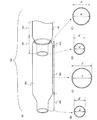
図1は、本発明の精製装置を模式的に示した断面図である。また、図2、図3は、本発明の精製装置の一部である精製部の斜視図、及び断面図である。 FIG. 1 is a cross-sectional view schematically showing a purification apparatus of the present invention. 2 and 3 are a perspective view and a cross-sectional view of a purification unit which is a part of the purification apparatus of the present invention.
本発明の精製装置100は、試料を気化し、目的物質を精製、回収するための精製部110と、試料を気化し、精製するための温度調節手段120と、精製部を固定するための固定手段130と、を有する。なお、本明細書で試料とは、目的物質、不純物、及び溶媒等が混在している物質のことを示す。
The
図1に示すように、温度調節手段120は、精製部110に近接して設けられており、精製部110は該温度調節手段120により温度勾配を付けられる。具体的には、試料が全て気化する温度領域、目的物質が析出又は凝縮する温度領域等、少なくとも目的物質を単離、精製、回収できるように、精製部110は温度勾配を付けられる。温度勾配は、一方向に温度が低くなるようにしてもよいし、精製部110の中央を高温領域となるようにし、両方向に温度が低くなるようにしてもよい。
As shown in FIG. 1, the temperature adjustment means 120 is provided in the vicinity of the
精製部110で気化した試料は、蒸気圧の低い方へ拡散していく。蒸気圧は一般に温度の上昇とともに増大する。したがって、気化した試料は温度勾配に従って、温度の低い方へ拡散していく。すなわち、気化した試料は精製管内の圧力及び温度勾配に従って、液体または固体に状態変化する温度で、液体として凝縮または固体として析出する。なお、試料が気化する温度領域が、精製部110の最も高温の領域となる。
The sample vaporized in the
温度調節手段120としては、ヒータ、ホットプレート等を用いればよく、精製部110(例えば、試料を気化する精製管の近傍等)に近接して設ければよい。なお、図1では温度調節手段120を精製部110に近接して1つのみ設けた場合を示したが、本発明はこれに限らず、複数個設けても構わない。温度調節手段120の設置場所や個数は、適宜変更可能である。また、精製部110にかけた温度勾配の状態を維持できるように、保温手段や、精製部110を囲う保護カバー等を設けるのが好ましい。
As the temperature control means 120, a heater, a hot plate, or the like may be used, and it may be provided in the vicinity of the purification unit 110 (for example, in the vicinity of a purification tube for vaporizing a sample). Although FIG. 1 shows a case where only one temperature adjusting means 120 is provided in the vicinity of the
なお、精製部110の温度調節をする際に、試料が気化する温度、目的物質が析出又は凝縮する温度等の温度領域を最適な温度に設定する必要がある。これは、目的物質の分解点、昇華点、又は沸点等を調べ、設定すればよい。
When the temperature of the
次に、精製部110について、図2、図3を用いて詳しく説明する。図2(A)は精製部110の有する2つの精製管の斜視図であり、図2(B)は図2(A)の破線M−Lで表される部分の断面に相当する。図3(A)には、図2(A)で示した精製部110のうち、第2の精製管202と、第2の精製管202と第1の精製管201との遊嵌部を拡大した図を示す。
Next, the refinement |
精製部110は、少なくとも2つ以上の精製管が連なって構成する。精製部110に配置する精製管の個数は、適宜変更可能である。具体的には、試料を配置するための第1の精製管201と、精製されて析出又は凝縮した目的物質を回収するための第2の精製管202を含む、少なくとも2つ以上の精製管を有していればよい。なお、試料を配置した精製管の端部、或いは試料を配置した精製管に近い側の端部が、隣接する他の精製管の端部に遊嵌されるように配置する。すなわち、本実施の形態では、試料を配置した第1の精製管201が、第2の精製管202に遊嵌されるように配置する。
The
精製部110には、図2に示す実線の矢印のような温度勾配が付けられる。図2に示す実線は、紙面に対して右から左へと一方向に温度が低下していることを示している。試料を配置するための第1の精製管201を配置した場所には、精製部110において最も高い温度がかけられる。
A temperature gradient such as a solid arrow shown in FIG. The solid line shown in FIG. 2 indicates that the temperature is decreasing in one direction from right to left with respect to the paper surface. The highest temperature in the
また、本実施の形態では第1の精製管201に隣接して、目的物質を回収するための第2の精製管202を配置する。なお、本発明はこの限りでなく、第1の精製管201と第2の精製管202との間に1つ以上の精製管を配置しても構わない。目的物質を回収するための第2の精製管202を配置した領域が、予め調べた目的物質が析出又は凝縮する温度になればよい。つまり、第2の精製管202の中央に、目的物質が析出又は凝縮する温度がかけられるようにすればよい。
In the present embodiment, a
第1の精製管201、及び第2の精製管202の基本構造は、中空管である。さらに、第1の精製管201、及び第2の精製管202は、気化した試料(目的物質及び不純物を含む)が通過できるように、少なくとも隣接する精製管との遊嵌部の端部には開口が設けられている。精製管としては、ガラス、石英等からなる中空管を用いるのが好ましい。また、本発明はこれに限らず、試料や目的物質及び不純物と反応しない材料で、且つ目的物質の回収時に目的物質中に混入せず、実施温度に耐えうる材料であればよい。本実施の形態では、第1の精製管201及び第2の精製管202の両端部に開口が設けられている。もちろん、第1の精製管201において、他の精製管に遊嵌されない一方の端部、或いは第2の精製管202の一方の端部は閉じられていても構わない。なお、常圧で精製する場合において、精製部110を密閉して加熱すると管内の圧力が上がる場合があり、非常に危険である。ゆえに、どちらか一方の端部は開けておかねばならない。
The basic structure of the
図3(A)に示すように、第1の精製管201は、第1の端部、中央部321、第2の端部331の領域を有している。同様に、第2の精製管202は、第1の端部312、中央部322、及び第2の端部332の領域を有している。少なくとも、第1の精製管201及び第2の精製管202において、遊嵌部となる第1の精製管201の第2の端部331及び第2の精製管202の第1の端部312には、開口が設けられている。なお、図3(A)では、第1の精製管201の第1の端部については省略している。
As shown in FIG. 3A, the
また、第2の精製管202の第2の端部332において、気化した試料の流路と垂直方向の断面図を図3(B)に示し、第2の精製管202の中央部322において、気化した試料の流路と垂直方向の断面図を図3(C)に示す。さらに、第1の精製管201の第2の端部331において、気化した試料の流路と垂直方向の断面図を図3(D)に示し、第2の精製管202の第1の端部312において、気化した試料の流路と垂直方向の断面図を図3(E)に示す。
In addition, a cross-sectional view perpendicular to the flow path of the vaporized sample at the
図3(B)に示す第2の精製管の第2の端部332において、管の肉厚を含まない断面の直径を管内径b1とし、管の肉厚を含む断面の直径を管外径b2とする。また、図3(C)に示す第2の精製管202の中央部322において、管の肉厚を含まない断面の直径を管内径c1とし、管の肉厚を含む断面の直径を管外径c2とする。また、図3(D)に示す第1の精製管201の第2の端部331において、管の肉厚を含まない断面の直径を管内径d1とし、管の肉厚を含む断面の直径を管外径d2とする。また、図3(E)に示す第2の精製管202の第1の端部312において、管の肉厚を含まない断面の直径を管内径e1とし、管の肉厚を含む断面の直径を管外径e2とする。なお、管内径b1を有する断面と、管内径c1を有する断面と、管内径e1を有する断面は、配置する際に簡便になる点で、同心円であるのが好ましい。 At the second end 332 of the second purification tube shown in FIG. 3 (B), the diameter of the cross section that does not include the thickness of the tube and the tube inner diameter b 1, the diameter of the cross section including the thickness of the tube outside the tube and the diameter b 2. Further, extravascular in the central portion 322 of the second purification tube 202 shown in FIG. 3 (C), and the diameter of the cross section that does not include the thickness of the tube and the tube inner diameter c 1, the diameter of the cross section including the thickness of the tube the diameter c 2. Further, at the second end 331 of the first purification tube 201 shown in FIG. 3 (D), and the diameter of the cross section that does not include the thickness of the tube and the tube inner diameter d 1, the diameter of the cross section including the thickness of the tube the the outer diameter d 2. Further, at the first end 312 of the second purification tube 202 shown in FIG. 3 (E), the diameter of the cross section that does not include the thickness of the tube and the tube inner diameter e 1, the diameter of the cross section including the thickness of the tube the the outer diameter e 2. The cross section having the tube inner diameter b 1 , the cross section having the tube inner diameter c 1, and the cross section having the tube inner diameter e 1 are preferably concentric circles because they are easy to arrange.
また、第2の精製管202において、第2の端部332の肉厚と、中央部322の肉厚と、第1の端部312の肉厚は、精製管の強度を保つため、或いは温度が不均一になることを防ぐため、同一にするのが好ましい。また、同様に第1の精製管201においても、第2の端部331の肉厚と、中央部321の肉厚と、第1の端部の肉厚は、精製管の強度を保つため、或いは温度が不均一になることを防ぐため、同一にするのが好ましい。
In the
第1の精製管201は、隣接する第2の精製管202に、図2、図3(A)に示すように遊嵌されている。本発明は、一の精製管が、隣接する他の精製管の開口に遊嵌されることを特徴としており、他の精製管の一の精製管が遊嵌する側の端部における最端部の管内径を、一の精製管の他の精製管に遊嵌される側の端部における管外径よりも大きくすることで、第1の精製管を第2の精製管に遊嵌することができる。本実施の形態では、第1の精製管201と第2の精製管202とが隣接しており、第1の精製管201の第2の端部331が、第2の精製管202の第1の端部312の開口に遊嵌されている。すなわち、第2の精製管202の第1の端部312における最端部の管内径e1を、第1の精製管201の第2の端部331における最端部の管外径d2よりも大きくすることで、第1の精製管を第2の精製管に遊嵌することができる。その結果、該遊嵌部から気化した試料の流出を防ぐ構造とすることができる。なお、下記、数式(1)を満たすのが好ましい。
The
![]()
![]()
更に好ましくは、下記数式(2)を満たすのが好ましい。 More preferably, the following mathematical formula (2) is satisfied.
![]()
![]()
![]()
![]()
本発明のように、第1の精製管201を第2の精製管202に遊嵌させることで、摺り合わせ部を設けた構造よりも取り扱いが簡便になる。これは、摺り合わせ部に物質が析出すると精製管同士が固着され易いのに対し、遊嵌状態は遊びを持っているため固着されにくいためである。
As in the present invention, the
また、本発明は、一の精製管が、隣接する他の精製管の開口に遊嵌される部分において、精製管からの試料や目的物質の漏れを防ぐ構造としていることも特徴とする。したがって、他の精製管において、中央近傍の管内径は一の精製管を遊嵌する側の端部における管内径よりも大きいことを特徴としている。本実施の形態では、第1の精製管201と第2の精製管202との遊嵌部において、試料や目的物質の漏れを防ぐ構造としている。特に、目的物質を液体として凝縮する場合に顕著な効果がある構造としている。具体的には、第2の精製管202において、中央部322の管内径c1は第1の端部312の管内径e1よりも大きく、第2の精製管202の第1の端部312の管内径e1は第1の精製管201の第2の端部331の管外径d2よりも大きいことを特徴としている。
In addition, the present invention is also characterized in that one purification tube has a structure that prevents leakage of a sample and a target substance from the purification tube in a portion loosely fitted into an opening of another adjacent purification tube. Therefore, in another refinement | purification pipe | tube, the pipe internal diameter of the center vicinity is larger than the pipe internal diameter in the edge part by the side which loosely fits one refinement | purification pipe | tube. In this embodiment, the loose fitting portion between the
したがって、本発明は、第1の精製管を第2の精製管に遊嵌し、該遊嵌部から試料、或いは目的物質等の漏れを防ぐ構造とするため、下記、数式(4)を満たす必要がある。 Therefore, in the present invention, the first purification tube is loosely fitted to the second purification tube to prevent leakage of a sample or a target substance from the loose fitting portion. There is a need.
![]()
![]()
なお、遊嵌部から試料、或いは目的物質等の漏れを防ぐ構造とするため、下記数式(5)を満たすのが好ましい。 In addition, in order to make it a structure which prevents the leakage of a sample or a target substance from a loose fitting part, it is preferable to satisfy | fill following numerical formula (5).
![]()
![]()
更に好ましくは、下記数式(6)を満たすと良い。

最も好ましくは、下記数式(7)且つ下記数式(8)を満たすと良い。 Most preferably, the following formula (7) and the following formula (8) are satisfied.
![]()
![]()
![]()
![]()
なお、遊嵌部において、第1の精製管201と第2の精製管202は接してもよいし、間隙があってもよい。また、第1の精製管201は、第2の精製管202の第1の端部312にほんの僅かでも入り込んでいればよい。好ましくは第1の精製管201と第2の精製管202が接触するところまで入り込んでいるとよい。
In the loose fitting portion, the
さらに、本発明は、一の精製管が、隣接する他の精製管の開口に遊嵌され、且つ一の精製管、又は他の精製管自体が試料や目的物質が漏れにくい構造であることを特徴とする。したがって、一の精製管、又は他の精製管において、中央近傍の管内径が最も大きいことを特徴としている。本実施の形態では、第2の精製管202において、中央部322の管内径c1が、第1の端部312の管内径e1及び第2の端部332の管内径b1よりも大きいことを特徴としている。本発明は、前述した数式(1)を満たすとともに、下記数式(9)且つ下記数式(10)を満たすことを特徴としている。
Furthermore, according to the present invention, one purification tube is loosely fitted into an opening of another adjacent purification tube, and the one purification tube or the other purification tube itself has a structure in which a sample or a target substance is difficult to leak. Features. Therefore, one refinement tube or another refinement tube is characterized in that the inner diameter of the tube near the center is the largest. In this embodiment, in the
![]()
![]()
![]()
![]()
なお、1つの精製管から試料や目的物質が漏れない構造とするため、前述した数式(2)又は数式(3)を満たすとともに、下記数式(11)且つ下記数式(12)を満たすのが好ましい。 In addition, in order to make the sample and the target substance not leak from one purification tube, it is preferable to satisfy the following formula (11) and the following formula (12) as well as the above formula (2) or formula (3). .
![]()
![]()
![]()
![]()
更に好ましくは、前述した数式(2)又は数式(3)を満たすとともに、下記数式(13)且つ下記数式(14)を満たすのが好ましい。 More preferably, it satisfies the above-described mathematical formula (2) or (3) and preferably satisfies the following mathematical formula (13) and the following mathematical formula (14).
![]()
![]()
![]()
![]()
この構造は、特に、目的物質を液体として凝縮する場合に顕著な効果がある。 This structure is particularly effective when the target substance is condensed as a liquid.
また、本発明は、遊嵌部に摺り合わせ部を設けていないことも特徴としている。精製管同士の遊嵌部において摺り合わせ部を設けないことにより、潤滑剤等を用いる必要がなくなり、潤滑剤等による目的物質の純度を下げる恐れが少なくなる。また、精製管を取り外す際に、摺り合わせ部に試料や目的物質が付着し、固まることで取り外すことが出来なくなる等の問題を防ぐことができ、精製装置の取り扱いを簡便にできる。 The present invention is also characterized in that no sliding portion is provided in the loose fitting portion. By not providing the sliding portion in the loose fitting portion between the purified tubes, it is not necessary to use a lubricant or the like, and the possibility of lowering the purity of the target substance by the lubricant or the like is reduced. Moreover, when removing a refinement | purification pipe | tube, the sample and a target substance adhere to a rubbing part, the problem that it becomes impossible to remove because it hardens | cures can be prevented, and handling of a refiner | purifier can be simplified.
本発明のように、隣接する精製管同士、例えば第1の精製管201が第2の精製管202に遊嵌される構造にすることで、精製管同士の継ぎ目から気化した試料等が流出することを防ぐことができる。したがって、高収率で目的物質を得ることができる。
As in the present invention, by making a structure in which the adjacent purification tubes, for example, the
さらに、本発明の構成にすることで、特に目的物質が液体として凝縮する場合、隣接する精製管同士、例えば第1の精製管201から第2の精製管202への試料の混入、或いは第2の精製管202から第1の精製管への目的物質の混入を防ぐことができ、非常に効果的である。したがって、高い純度の目的物質を得ることができる。
Furthermore, with the configuration of the present invention, particularly when the target substance condenses as a liquid, the sample is mixed into adjacent purification tubes, for example, the
また、本発明の構成にすることで、1つの精製管、例えば第1の精製管201、或いは第2の精製管202自体を、試料又は目的物質の漏れを防ぐ構造とすることができる。したがって、高収率で目的物質を得ることができる。
Further, with the configuration of the present invention, one purification tube, for example, the
第1の精製管201の中央部321、及び第2の精製管202の中央部322については、一様の管内径、及び管外径を持つ円柱状の中空管とすればよい。なお、本発明はこれに限定されず、中央部が多様な管内径の領域を有してもよいが、ある程度、一定の管内径及び管外径を持つ領域を有していたほうが、精製部110を固定しやすい。
The
第1の精製管201の第2の端部331の形状は、中央部321から第2の端部331の最端部にかけ、連続的に管外径が小さくなるような形状とすればよい。或いは、ある点までは連続的に管外径が小さくなるような形状とし、ある点からは管外径が大きくなるような形状としてもよいし、その逆の形状としてもよい。また、一定の管外径が連続する領域があるような形状としてもよい。少なくとも、第1の精製管201及び第2の精製管202の遊嵌部において、第1の精製管201の第2の端部331の最端部の管外径d2が、第2の精製管202の第1の端部312の最端部の管内径e1よりも小さければよい。また、第1の精製管201において、気化した試料の流路と垂直方向の断面の形状は特に限定されない。
The shape of the
また、第1の精製管201の第2の端部331の開口から試料の漏れを防ぐ構造とするためには、前述した数式(4)を満たすのが好ましい。
In order to prevent the sample from leaking from the opening of the
なお、第1の精製管201の第2の端部331には曲率を持たせるのが好ましい。このような形状にすることで、継ぎ目から気化した試料が流出する、又は試料が隣接する精製管に混入することを防ぐことができる。特に、試料又は目的物質が液体の場合の混入を防ぐことができる。また、固体として析出した目的物質を薬さじ等で容易に回収することが可能となる。さらに、曲率を持たすことで精製管の強度が増し、精製管自体が破損しにくくすることができる。
The
第2の精製管202の第2の端部332については、特に限定はないが、試料の漏れを防ぐ構造とするためには、前述した数式(9)且つ数式(10)を満たすのが好ましい。また、前述した数式(9)且つ数式(10)を満たし、第1の精製管201の第2の端部331と同様の形状とするのが好ましい。また、目的物質を液体として凝縮するための精製装置に用いる場合以外は、中央部322と同一の形状としても構わない。第2の精製管202の第2の端部332が他の何れの精製管にも遊嵌されないのであれば、最端部の開口は、設けられてなくともよい。
The
第2の精製管202の第1の端部312の形状は、中央部322から第1の端部312の最端部にかけて、連続的に管内径が小さくなるような形状とすればよい。或いは、ある点までは連続的に管内径が小さくなるような形状とし、ある点からは管内径が大きくなるような形状としてもよいし、その逆の形状としてもよい。また、一定の管内径が連続する領域があるような形状としてもよい。少なくとも、第1の精製管201と第2の精製管202の遊嵌部において、第2の精製管202の第1の端部312の最端部の管内径e1が、第1の精製管201の第2の端部331の最端部の管外径d2よりも大きければよい。また、第2の精製管202において、気化した試料の流路と垂直方向の断面の形状は特に限定されない。
The shape of the
また、第2の精製管202の第1の端部312の開口から目的物質の漏れを防ぐ構造とするためには、前述した数式(4)を満たすのが好ましい。
Further, in order to obtain a structure that prevents leakage of the target substance from the opening of the
なお、第2の精製管202の第1の端部312には、曲率を持たせるのが好ましい。このような形状にすることで、継ぎ目から気化した試料が流出する、又は試料が隣接する精製管に混入することを防ぐことができる。特に、試料が液体の場合の混入を防ぐことができる。また、曲率を持たすことで精製管の強度が増し、精製管自体を破損しにくくすることができる。
It is preferable that the
また、第1の精製管201の第1の端部についても、第2の精製管202の第1の端部312と同様の形状とすればよい。また、他の何れの精製管も遊嵌しないのであれば、中央部321と同一の形状としても構わない。なお、第1の精製管201において、中央部321の管内径が、第1の端部の管内径よりも大きい方が、第1の精製管201から試料が漏れにくい。すなわち、第1の精製管において、中央部321の管内径を最も大きくすると、第1の精製管201から試料を漏れにくくすることができる。なお、最端部の開口は、設けられてなくともよい。
In addition, the first end of the
なお、先に述べたように、本発明は、必ずしも試料を配置する精製管と、精製された目的物質を回収するための精製管を隣接して配置する必要はない。したがって、試料を配置するための精製管を本実施の形態の第1の精製管201とし、該第1の精製管201と隣接して第2の精製管202を配置し、該第2の精製管202と隣接して目的物質を回収するための精製管を配置してもよい。さらに、試料を配置する精製管と目的物質を回収する精製管との間に2つ以上の精製管を配置してもよい。また、目的物質を回収する精製管にさらに隣接して精製管を配置してもかまわない。なお、隣接する精製管同士は、本実施の形態の第1の精製管201と第2の精製管202で説明したように、遊嵌していることを特徴とする。この時、試料を配置した精製管の端部、或いは試料を配置した精製管に近い側の端部が、隣接する他の精製管の端部に遊嵌されるように配置する。
As described above, in the present invention, it is not always necessary to arrange a purification tube for arranging a sample and a purification tube for recovering the purified target substance adjacent to each other. Therefore, the purification tube for arranging the sample is the
本発明は、一の精製管が隣接する他の精製管に遊嵌されればよく、隣接する精製管同士は同一形状でなくともよい。また、本発明は、一の精製管が隣接する他の精製管に遊嵌されればよく、第1の端部、中央部、及び第2の端部の気化した試料の流路と垂直方向の断面は、同心円でなくともよい。なお、第1の端部、中央部、及び第2の端部の気化した試料の流路と垂直方向の断面が同心円である方が、配置する際に簡便になる。 In the present invention, one purification tube may be loosely fitted to another adjacent purification tube, and the adjacent purification tubes do not have to have the same shape. In the present invention, one purification tube may be loosely fitted to another adjacent purification tube, and the first end portion, the central portion, and the second end portion are perpendicular to the flow path of the vaporized sample. The cross section may not be concentric. It should be noted that it is easier to place the first end portion, the central portion, and the second end portion having concentric cross sections perpendicular to the flow path of the vaporized sample.
なお、本発明の精製装置100において、精製部110の両端部を閉じ、密閉してしまうと、常圧で加熱した際に非常に危険である。したがって、常圧で本精製装置を用いる場合には、少なくとも精製部110に1箇所は外界と通じる開口を設けなければならない。
In the
次に、図1に示す固定手段130は、少なくとも、一の精製管が隣接する精製管に遊嵌された状態を保持・固定できる手段であればよい。好ましくは、精製部110が長軸方向に水平となるように保持・固定できる手段であるとよい。固定手段130としては、精製部110を構成する各々の精製管をクランプ等で固定してもよいし、精製管を水平な台に配置してもよい。また、精製部110を構成する精製管の管外径よりも大きい管内径を有するガラス等の管の中に配置しても構わない。
Next, the fixing means 130 shown in FIG. 1 may be any means that can hold and fix at least a state in which one purification pipe is loosely fitted in an adjacent purification pipe. Preferably, the
以上で述べたように、本発明の構成にすることで、目的物質を高収率で得ることができる。また、遊嵌部からの試料、目的物質等の漏れを防ぐことができる。その結果、精製装置の汚染を防ぐことができ、作業効率を向上することができる。また、取り扱いが簡便な精製装置を提供することができる。 As described above, with the configuration of the present invention, the target substance can be obtained in high yield. Further, it is possible to prevent leakage of a sample, a target substance, and the like from the loose fitting portion. As a result, contamination of the refining device can be prevented and work efficiency can be improved. In addition, a purification apparatus that is easy to handle can be provided.
(実施の形態2)
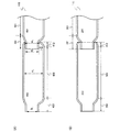
本実施の形態では、精製部を構成する精製管の形状の例について、図4を用いて説明する。図4(B)は、図3に示した精製部110の気化した試料の流路と平行方向の断面図に相当する。
(Embodiment 2)
In the present embodiment, an example of the shape of the purification tube constituting the purification unit will be described with reference to FIG. 4B corresponds to a cross-sectional view in a direction parallel to the flow path of the vaporized sample of the
図4(A)は、図4(B)に示す精製部より、さらに目的物質の漏れを防ぐ構造としたものである。具体的には、精製部410を構成する第1の精製管401と第2の精製管402との遊嵌部において、第2の精製管402の第1の端部412に設けられる開口、第1の端部412に遊嵌する第1の精製管401の第2の端部431に設けられる開口、及び第2の精製管402の中央部422の気化した試料の流路と垂直方向の断面が同心円でない構造としたものである。
FIG. 4A shows a structure that further prevents leakage of the target substance from the purification unit shown in FIG. 4B. Specifically, in the loose fitting portion between the
また、図4(A)の場合も、第2の精製管402に第1の精製管401を遊嵌するため、前述の数式(1)を満たす必要がある。また、遊嵌部から試料、或いは目的物質等の漏れを防ぐ構造とするためには、前述の数式(4)を満たせばよい。さらに、精製管自体から試料、或いは目的物質を漏らさない構造とするためには、前述の数式(9)且つ数式(10)を満たせばよい。なお、図4(A)中の破線で示すように、第2の精製管402の第2の端部432の管内径をb1とし、中央部422の管内径をc1とする。また、第1の精製管401の第2の端部の431の最端部の管外径をd2とし、第2の精製管402の第1の端部412の最端部に設けられた開口の管内径をe1とする。
In the case of FIG. 4A as well, since the
また、管内径b1を有する断面、及び管内径e1を有する断面を同心円とし、管内径b1を有する断面及び管内径e1を有する断面の中心を、管内径c1を有する断面の中心より上方に配置するのが好ましい。このように配置することで、精製管により多くの試料を配置することが可能となる。 The cross section having the tube inner diameter b 1 and the cross section having the tube inner diameter e 1 are concentric, and the center of the cross section having the tube inner diameter b 1 and the cross section having the tube inner diameter e 1 is the center of the cross section having the tube inner diameter c 1. It is preferable to arrange it further upward. By arranging in this way, it becomes possible to arrange many samples in the purification tube.
図4(A)のような構成にすることで、遊嵌部において、第2の精製管402の内縁と、遊嵌された第1の精製管401の最端部の外縁との最大距離(y)がより大きくなり、目的物質を漏れにくくすることができる。特に、目的物質が液体として凝縮する場合はその効果が顕著であり、隣接する精製管に混入する恐れがない。
4A, in the loose fitting portion, the maximum distance between the inner edge of the
なお、本実施の形態は、実施の形態1の構成と組み合わせることができる。
Note that this embodiment mode can be combined with the structure of
(実施の形態3)
本実施の形態では、精製部を構成する精製管の形状の例について、図5を用いて説明する。
(Embodiment 3)
In the present embodiment, an example of the shape of the purification tube constituting the purification unit will be described with reference to FIG.
図5(A)は、図4(B)に示す精製部110において、精製管の中央付近の内壁の一箇所に凸部を設けた構造としたものであり、その他は図4(B)と同じ構造である。したがって、図4(B)と同様に、第1の精製管5001は、隣接する第2の精製管5002に遊嵌されており、前述の数式(1)を満たす必要がある。また、図4(B)と同様に、必要に応じて前述の数式(4)、数式(9)且つ数式(10)を満たせばよい。
FIG. 5A shows a structure in which a refining portion is provided at one place on the inner wall near the center of the refining tube in the
図5(A)において、第1の精製管5001は、第1の端部、中央部5021、第2の端部5031を有する。同様に、第2の精製管5002も、第1の端部5012、中央部5022、第2の端部5032を有する。なお、図5(A)中の破線で示すように、第2の精製管5002の第2の端部5032の管内径をb1とし、中央部5022の管内径をc1とする。また、第1の精製管5001の第2の端部の5031の最端部の管外径をd2とし、第2の精製管5002の第1の端部5012の最端部に設けられた開口の管内径をe1とする。
In FIG. 5A, the
図5(A)は、図4(B)で示したものより、さらに精製管から試料及び目的物質の漏れを防ぐ構造となっている。具体的には、第2の精製管5002の中央部5022付近の内壁において、高さf1の凸部5040が設けられている。すなわち、中央部5022の他の領域の直径(管内径c1)よりも小さい高さ(f1)を有する凸部5040領域(管内径c1から凸部5040の頂点へと連続的に管内径が小さくなる領域)を、一箇所有する。なお、図5(B)は、図5(A)の破線o−o’で表される部分の断面図である。したがって、本発明の構造は、前述の数式(1)を満たすとともに、下記数式(15)も満たしている。
FIG. 5A has a structure that prevents leakage of the sample and the target substance from the purification tube more than that shown in FIG. Specifically, a
![]()
![]()
なお、好ましくは下記数式(16)を満たすと良い。 In addition, Preferably it is good to satisfy | fill following numerical formula (16).
![]()
![]()
更に好ましくは、下記数式(17)を満たすと良い。
![]()
![]()
最も好ましくは、下記数式(18)を満たすと良い。 Most preferably, the following mathematical formula (18) is satisfied.
![]()
![]()
図5(A)のような構造とすることで、第2の精製管5002の中央部5022付近の内壁に設けられた凸部5040で目的物質が塞き止められる。その結果、第1の精製管5001及び第2の精製管5002の遊嵌部、或いは第2の精製管5002の先端部分から、目的物質等が漏れるのを防ぐことができる。
With the structure as shown in FIG. 5A, the target substance is blocked by the
また、図5(A)のような構造とすることで、凸部5040と第1の端部5012との間の領域と、凸部5040と第2の端部5032との間の領域に、それぞれ析出又は凝集した物質の混同(コンタミネーション)を防ぐことができる。その結果、より純度の高い目的物質を得ることができる。
5A, the region between the
なお、凸部5040を設ける位置は図5(A)に示す位置に限定されず、第1の端部5012側寄りに設けてもよいし、或いは第2の端部5032側寄りに設けても構わない。凸部5040は第2の精製管5002の下面側に配置するのが好ましい。
Note that the position where the
また、第1の精製管5001の中央部5021付近の内壁にも同様に凸部を設けてもよい。第1の精製管5001の内壁に凸部を設けることで、遊嵌部や第1の精製管5001から試料等の漏れを防ぐことができる。また、第1の精製管5001の第1の端部側に他の精製管が遊嵌しない、又は第2の精製管5002の第2の端部5032側が他の精製管に遊嵌されないのであれば、最端部に開口は設けられなくともよい。
Similarly, a convex portion may be provided on the inner wall near the
図5(C)は、図4(A)に示す精製部410において、精製管の中央部5122付近の内壁の一箇所に凸部を設けた構造としたものであり、その他は図4(A)と同じ構造である。したがって、図4(A)と同様に、第1の精製管5101は、隣接する第2の精製管5102に遊嵌されており、前述の数式(1)を満たす必要がある。また、図4(A)と同様に、必要に応じて前述の数式(4)、数式(9)且つ数式(10)を満たせばよい。
FIG. 5C shows a structure in which a convex portion is provided at one place on the inner wall near the
図5(C)において、第1の精製管5101は、第1の端部、中央部5121、第2の端部5131を有する。同様に、第2の精製管5102も、第1の端部5112、中央部5122,第2の端部5132を有する。なお、図5(C)中の破線で示すように、第2の精製管5102の第2の端部5132の管内径をb1とし、中央部5122の管内径をc1とする。また、第1の精製管5101の第2の端部の5131の最端部の管外径をd2とし、第2の精製管5102の第1の端部5112の最端部に設けられた開口の管内径をe1とする。
In FIG. 5C, the
図5(C)は、図4(A)で示したものより、さらに精製管や遊嵌部から試料及び目的物質の漏れを防ぐ構造となっている。具体的には、第2の精製管5102の中央部5122付近の内壁において、高さf1の凸部5140が設けられている。すなわち、中央部5122の他の領域の直径(管内径c1)よりも小さい高さ(f1)を有する凸部5140領域(管内径c1から凸部5140の頂点へと連続的に管内径が小さくなる領域)を、一箇所有する。なお、図5(D)は、図5(C)の破線p−p’で表される部分の断面図である。したがって、本発明の構造は、前述の数式(1)を満たすとともに、前述の数式(15)も満たしている。
FIG. 5C has a structure that prevents leakage of the sample and the target substance from the purification tube and the loose fitting portion, as compared with the structure shown in FIG. Specifically, a
なお、好ましくは前述の数式(16)を満たすと良い。より好ましくは前述の数式(17)、最も好ましくは前述の数式(18)の比率を満たすと良い。 Note that it is preferable to satisfy the above-described formula (16). More preferably, the ratio of the above-described equation (17), and most preferably, the ratio of the above-described equation (18) may be satisfied.
図5(C)のような構造とすることで、第2の精製管5102の中央部5122付近の内壁に設けられた凸部5140で目的物質が塞き止められる。その結果、第1の精製管5101及び第2の精製管5202の遊嵌部、或いは第2の精製管5202の先端部分から、目的物質等の漏れを防ぐことができる。また、図5(A)と同様に、析出又は凝集した物質の混同(コンタミネーション)を防ぐことができる。その結果、より純度の高い目的物質を得ることができる。
With the structure shown in FIG. 5C, the target substance is blocked by the
なお、凸部5140を設ける位置は図5(C)に示す位置に限定されず、第1の端部5112側寄りに設けてもよいし、或いは第2の端部5132側寄りに設けても構わない。凸部5140は第2の精製管5102の下面側に配置するのが好ましい。
Note that the position where the
また、第1の精製管5101の中央部5121付近の内壁にも同様に凸部を設けてもよい。第1の精製管5101の内壁に凸部を設けることで、遊嵌部や第1の精製管5101から試料等の漏れを防ぐことができる。また、第1の精製管5101の第1の端部側に他の精製管が遊嵌しない、又は第2の精製管5102の第2の端部5132側が他の精製管に遊嵌されないのであれば、最端部に開口は設けられなくともよい。
Similarly, a convex portion may be provided on the inner wall near the
図5(E)は、図5(A)に示す精製部110において、精製管の中央部付近の内壁に更に1箇所、すなわち中央部付近の内壁に2箇所の凸部を設けた構造としたものである。2箇所の凸部は、対向して設けられている。対向して設けられた凸部以外は、図5(A)と同じ構成であり、前述の数式(1)を満たす必要がある。また、図5(A)と同様に、必要に応じて前述の数式(4)、数式(9)且つ数式(10)を満たせばよい。
FIG. 5E shows a structure in which the
また、図5(A)と同様、第1の精製管5201は、第1の端部、中央部5221、第2の端部5231を有する。同様に、第2の精製管5202も、第1の端部5212、中央部5222、第2の端部5232を有する。なお、図5(E)中の破線で示すように、第2の精製管5202の第2の端部5232の管内径をb1とし、中央部5222の管内径をc1とする。また、第1の精製管5201の第2の端部の5231の最端部の管外径をd2とし、第2の精製管5202の第1の端部5212の最端部に設けられた開口の管内径をe1とする。
Similarly to FIG. 5A, the
また、第2の精製管5202の中央部5222付近の内壁には、高さf1の凸部が対向して2箇所設けられている。すなわち、中央部5222の他の領域の直径(管内径c1)よりも小さい高さ(f1)を有する2箇所の凸部を有する凸部領域5240(管内径c1から凸部の頂点へと連続的に管内径が小さくなる領域)を有する。なお、図5(F)は、図5(E)の破線q―q’で表される部分の断面図であり、凸部領域5240の断面の円形の直径を管内径g1とする。本発明の構造は、前述の数式(1)を満たすとともに、下記数式(19)も満たしている。
Further, on the inner wall in the vicinity of the
![]()
![]()
なお、凸部領域5240を設ける位置は図5(E)に示す位置に限定されず、第1の端部5212側寄りに設けてもよいし、或いは第2の端部5232側寄りに設けても構わない。
Note that the position where the
なお、管内径g1は、管内径c1よりも小さく、好ましくは下記数式(20)を満たすと良い。 Incidentally, the inner tube diameter g 1 is smaller than the tube inner diameter c 1, may preferably satisfy the following equation (20).
![]()
![]()
更に好ましくは、下記数式(21)を満たすと良い。
![]()
![]()
最も好ましくは、下記数式(22)を満たすと良い。 Most preferably, the following mathematical formula (22) is satisfied.
![]()
![]()
もちろん、第1の精製管5201の中央部5221付近の内壁にも同様に凸部領域を設けてもよい。図5(E)のような構成とすることで、遊嵌部や第1の精製管5201、及び第2の精製管5202から試料や目的物質等の漏れを防ぐことができる。さらに、図5(A)と同様に、析出又は凝縮した物質の混同(コンタミネーション)を防ぐことができる。その結果、より純度の高い目的物質を得ることができる。また、第1の精製管5201の第1の端部側に他の精製管が遊嵌しない、又は第2の精製管5202の第2の端部5232側が他の精製管に遊嵌されないのであれば、最端部に開口は設けなくともよい。
Of course, you may provide a convex area | region similarly to the inner wall of
図5(G)は、図5(C)に示す精製部410において、精製管の中央部付近の内壁に更に1箇所、すなわち中央部付近の内壁に2箇所の凸部を設けた構造としたものである。2箇所の凸部は対向して設けられている。対向して設けられた凸部以外は、図5(C)と同じ構成である。したがって、前述の数式(1)を満たす必要がある。また、必要に応じて前述の数式(4)、数式(9)且つ数式(10)を満たせばよい。
FIG. 5G shows a structure in which, in the
図5(C)と同様、第1の精製管5301は、第1の端部、中央部5321、第2の端部5331を有する。同様に、第2の精製管5302も、第1の端部5312、中央部5322、第2の端部5332を有する。なお、図5(G)中の破線で示すように、第2の精製管5302の第2の端部5332の管内径をb1とし、中央部5322の管内径をc1とする。また、第1の精製管5301の第2の端部の5331の最端部の管外径をd2とし、第2の精製管5302の第1の端部5312の最端部に設けられた開口の管内径をe1とする。
As in FIG. 5C, the
また、第2の精製管5302の中央部5322付近の内壁には、高さf1の凸部が対向して2箇所設けられている。すなわち、中央部5322の他の領域の直径(管内径c1)よりも小さい高さ(f1)を有する2箇所の凸部を有する凸部領域5340(管内径c1から凸部の頂点へと連続的に管内径が小さくなる領域)を有する。なお、図5(H)は、図5(G)の破線r―r’で表される部分の断面図であり、凸部領域5340の断面の円形の直径を管内径g1とする。本発明の構造は、前述の数式(1)を満たすとともに、前述の数式(13)も満たしている。なお、凸部領域5340を設ける位置は図5(G)に示す位置に限定されず、第1の端部5312側寄りに設けてもよいし、或いは第2の端部5332側寄りに設けても構わない。
Further, on the inner wall in the vicinity of the
なお、図5(C)と同様に、図5(E)中の破線で示す管内径g1は管内径c1よりも小さい。好ましくは前述の数式(20)、より好ましくは前述の数式(21)、最も好ましくは前述の数式(22)満たすと良い。 As in the FIG. 5 (C), the tube inner diameter g 1 indicated by a broken line in FIG. 5 (E) is smaller than the tube inner diameter c 1. It is preferable to satisfy the above formula (20), more preferably the above formula (21), and most preferably the above formula (22).
もちろん、第1の精製管5301の中央部5321付近の内壁にも同様に凸部領域を設けてもよい。図5(D)のような構成とすることで、遊嵌部や第1の精製管5301、及び第2の精製管5302から試料や目的物質等の漏れを防ぐことができる。さらに、図5(C)と同様に、析出又は凝集した物質の混同(コンタミネーション)を防ぐことができる。その結果、より純度の高い目的物質を得ることができる。また、第1の精製管5301の第1の端部側に他の精製管が遊嵌しない、又は第2の精製管5302の第2の端部5332側が他の精製管に遊嵌されないのであれば、最端部に開口は設けなくともよい。
Of course, you may provide a convex area | region similarly in the inner wall near the
なお、本実施の形態は、実施の形態1の構成と組み合わせることができる。
Note that this embodiment mode can be combined with the structure of
(実施の形態4)
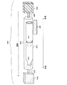
本実施の形態では、実施の形態1乃至3の構成に加え、精製装置に気体供給手段、真空排気手段を設けた構成について、図6を用いて説明する。その他の構成については、実施の形態1乃至実施の形態3と同じであるので、説明は省略する。
(Embodiment 4)
In this embodiment, a configuration in which a gas supply unit and a vacuum exhaust unit are provided in the purification apparatus in addition to the configurations of
本実施の形態の精製装置6000は、精製部6010と、温度調節手段6020と、固定手段6030と、気体供給手段6040と、真空排気手段6050とを有する。
The
精製部6010は、試料を配置するための第1の精製管6011、及び目的物質を回収するための第2の精製管6012を有する。本実施の形態では、固定手段6030としてガラス、石英等の管(本明細書では、外管と記す)を用い、精製部6010を構成する精製管を外管の内側に挿入して、精製部6010を固定している。なお、固定手段6030である外管の材料は、ガラス、石英に限定されず、試料や目的物質及び不純物と反応しない材料で、且つ目的物質の回収時に目的物質中に混入せず、実施温度に耐えうる材料であればよい。また、真空排気手段6050として真空ポンプを用いる場合、減圧しても強度を保てる材料であればよい。
The
また、固定手段6030は、ガラス管以外にも真空チャンバー等、気密状態を保つことができ、且つ精製部6010の有する精製管同士の遊嵌部が保持できる手段であればよい。なお、固定手段6030は精製管同士の遊嵌部を保持する役割のみとし、それとは別に精製部6010を気密状態に保つ手段を設けてもかまわない。
In addition to the glass tube, the
精製部6010は、実施の形態1乃至3に説明したように、第1の精製管6011が隣接する第2の精製管6012に遊嵌されている。なお、第1の精製管6011及び第2の精製管6012は、実施の形態1乃至3で示したものを用いればよい。また、本実施の形態では、精製部6010は2つの精製管で構成したが、本発明はこれに限らず、3つ以上の精製管で構成されていてもよい。
As described in
温度調節手段6020は、精製部6010に近接して設ける。温度調節手段6020としては、少なくとも試料を気化する温度に加熱できるよう、ヒータ、ホットプレート等の加熱器を設ければよい。また、試料が配置される第1の精製管6011に、精製部6010の最も高温度がかけられる。
The temperature adjusting means 6020 is provided in the vicinity of the
また、精製部6010に温度勾配をかけた後、温度勾配の状態を保つため、精製部6010全体に保温機能のついた温度調節手段6020を設けてもよい。また、精製部6010、或いは固定手段6030を囲むように金属カバー、ガラスウール等の保護カバーを設け、温度勾配の状態を保ってもよい。
In addition, in order to maintain the temperature gradient after the temperature gradient is applied to the
気体供給手段6040は、精製部6010の端部に設ける。具体的には、試料を配置する第1の精製管6011に近い側の端部に設ける。気体供給手段6040及び精製部6010を含む固定手段6030は、配管6060等を用いて連結すればよい。気体供給手段6040から精製部6010にアルゴン(Ar)、窒素(N2)等の不活性ガスをキャリアガスとして導入することで、気化した試料を円滑に拡散することができる。その結果、一方向に効率よく目的物質を析出又は凝縮させることができる。
The gas supply means 6040 is provided at the end of the
なお、気体供給手段6040から精製部6010に導入するキャリアガスは不活性ガス以外を用いてもよいが、不活性ガスの方が試料や目的物質等の酸化、分解等を抑えることができるので好ましい。もちろん、精製部6010に存在する試料や目的物質等と反応するガスを用いてはならない。
The carrier gas introduced into the
一方、真空排気手段6050は、気体供給手段6040が設けられた反対側の精製部6010の端部に設ける。真空排気手段6050及び精製部6010を含む固定手段6030は、配管6070等を用いて連結すればよい。真空排気手段6050としては、真空ポンプ等を用いることができる。また、精製部6010と真空排気手段6050との間に液体窒素等を用いた冷却トラップを設けてもよい。真空排気手段6050によって精製部6010内を真空状態とし、減圧することが可能となる。その結果、試料が気化する温度を下げることができる。すなわち、真空排気手段6050を用いて精製部6010を減圧すると、試料の昇華又は蒸発温度が低下し、大気圧下では気化しない試料も気化させることが可能となる。
On the other hand, the
なお、本実施の形態では、気体供給手段6040及び真空排気手段6050の両方の手段を設けた構成としたが、本発明はこれに限らず、どちらかの手段のみを設けてもよい。ただし、気体供給手段6040のみ設ける場合、精製部6010が密閉されないようにする。また、真空排気手段6050を設ける場合には、ガラス、石英等の外管、或いは真空チャンバー等の中に精製部6010を配置することが好ましい。
In the present embodiment, both the gas supply means 6040 and the vacuum exhaust means 6050 are provided. However, the present invention is not limited to this, and only one of the means may be provided. However, when only the gas supply means 6040 is provided, the
本実施の形態のように、精製装置6000に気体供給手段6040、及び真空排気手段6050を配置することで、目的物質を効率よく精製することができる。また、精製速度を速くすることが可能となり、作業効率を向上することができる。さらに、大気中では気化しない試料に関しても精製することが可能となり、簡易に目的物質を得ることができる。
By disposing the gas supply means 6040 and the vacuum evacuation means 6050 in the
なお、本実施の形態は、実施の形態1乃至実施の形態3の構成と組み合わせることができる。
Note that this embodiment mode can be combined with the structures of
(実施の形態5)
本実施の形態では、実施の形態1乃至実施の形態4で示した精製装置を用いた精製方法について、図7を用いて説明する。特に、固体試料を用いて、目的物質及び不純物を固体として析出する昇華精製方法について、説明する。
(Embodiment 5)
In this embodiment, a purification method using the purification device described in any of
精製装置6000は、実施の形態4と同じ構成であり、精製部6010、温度調節手段6020、固定手段6030、気体供給手段6040、真空排気手段6050とを有する。精製部6010は、試料を配置するための第1の精製管6011と、目的物質を回収する第2の精製管6012から構成されている。もちろん、本発明はこれに限らず、3つ以上の精製管を有していてもよい。
The
まず、第2の精製管6012に遊嵌される前の第1の精製管6011に固体試料7011を配置する。固体試料は、第1の精製管6011に直接配置してもよいし、箱状、筒状等の容器に入れ、該試料の入った容器を第1の精製管6011に挿入してもよい。試料を入れる容器は、試料と化学的に反応しない材料を用いたものであれば特に限定はないが、好ましくはガラス、石英等を用いるとよい。
First, the
次いで、固定手段6030により、精製部6010を固定する。固定手段6030としては、第1の精製管6011及び第2の精製管6012の有する最大管外径よりも大きい管内径を有する管(以下、外管とする)を用いる。外管は、一様の管内径を有するものが好ましい。
Next, the
固定手段6030である外管の中に、第1の精製管6011及び第2の精製管6012を挿入し、第2の精製管6012に第1の精製管6011を遊嵌する。なお、固定手段6030である外管の中に第1の精製管6011及び第2の精製管6012を挿入した後、固体試料を入れた容器を挿入してもかまわない。
The
また、固定手段6030である外管を長軸方向に水平に保持することが好ましい。なお、本実施の形態では固定手段6030を管としたが、本発明はこれに限らず、少なくとも精製部6010を構成する精製管の遊嵌部が保持できるように固定できる手段であればよい。ただし、精製部6010を真空状態にするのであれば、精製部6010を気密状態にできるガラス、石英等からなる管や真空チャンバーを固定手段6030として用いるのが好ましい。
Moreover, it is preferable to hold | maintain the outer tube which is the fixing means 6030 horizontally in a major axis direction. In the present embodiment, the fixing means 6030 is a tube. However, the present invention is not limited to this, and any means can be used as long as it can be fixed so that at least the loose fitting portion of the purification tube constituting the
本発明の精製部6010を用いることで、第1の精製管6011内の試料が固定手段6030である外管に漏れたり、隣接する第2の精製管6012に混入することを防ぐことができる。
By using the
次いで、配管6060、配管6070等を用いて、精製部6010を含む固定手段6030に気体供給手段6040、及び真空排気手段6050を連結する。なお、気体供給手段6040は、精製部6010の第1の精製管6011に近い端部側に配置する。また、真空排気手段6050は、精製部6010のもう一方の端部に配置する。そして、固定手段6030の外管を含む精製部6010を気密状態にする。
Next, the gas supply means 6040 and the vacuum exhaust means 6050 are connected to the fixing means 6030 including the
次いで、温度調節手段6020を用いて、精製部6010に温度勾配をかける。温度調節手段6020としては、ヒータ、ホットプレート等の加熱器を用いればよい。また、温度勾配をかけた後、温度勾配の状態を保つように保温手段を設けてもよい。これらの温度調節手段6020は精製部6010に近接して設けてもよいし、更に固定手段6030である外管の外側に設けても構わない。更に、温度勾配の状態を保つように、精製部6010、或いは固定手段6030である外管を囲うように、金属やガラスウール等からなる保護カバーを設けてもよい。
Next, a temperature gradient is applied to the
温度調節手段6020により第1の精製管6011に配置された固体試料7011を気化する。このとき、気体供給手段6040から精製部6010にキャリアガスを導入し、真空排気手段6050により精製部6010内を真空状態にする。
The
気化した試料は、精製部6010の温度勾配にしたがって、温度の低い方へ拡散していく。本実施の形態では、精製部6010において、気体供給手段6040が配置された側から真空排気手段6050が配置された側へと、一方向に温度が低下している。なお、気体供給手段6040からのキャリアガスの導入により、気化した試料を円滑に拡散させることができる。
The vaporized sample diffuses toward the lower temperature according to the temperature gradient of the
目的物質を回収するための第2の精製管6012は、温度調節手段6020により、目的物質が析出する温度領域とする。そして、気化した試料のうち、精製された目的物質7012のみが第2の精製管6012に析出する。
The
本実施の形態では、精製部6010は2つの精製管を有する構成としたが、本発明はこれに限らず、3つ以上の精製管を有する構成としてもよい。例えば、目的物質よりも析出温度が高い不純物を回収するための精製管や、目的物質よりも析出温度が低い不純物を回収するための精製管等を配置しても構わない。なお、3つ以上の精製管を配置する場合も、隣接する精製管同士の遊嵌部は、本発明の構成を用いることとする。すなわち、一の精製管は、隣接する精製管に遊嵌されるものとする。
In the present embodiment, the
また、本実施の形態の精製装置6000には、気体供給手段6040及び真空排気手段6050を設けたが、本発明はこれに限らず、何れかの手段のみを設けてもよいし、両方の手段とも設けなくても構わない。
Further, although the gas supply means 6040 and the vacuum evacuation means 6050 are provided in the
本発明の精製装置を用いて昇華精製を行うことで、目的物質を効率よく精製することができ、高収率を達成することができる。 By performing sublimation purification using the purification apparatus of the present invention, the target substance can be efficiently purified, and a high yield can be achieved.
なお、本実施の形態は、実施の形態1乃至実施の形態4と組み合わせることができる。
Note that this embodiment mode can be combined with any of
(実施の形態6)
本実施の形態では、実施の形態1乃至実施の形態4で示した精製装置を用いた精製方法について、図8を用いて説明する。特に、液体試料を用いて、目的物質及び不純物を液体として凝縮する蒸留方法について説明する。
(Embodiment 6)
In this embodiment, a purification method using the purification device described in any of
精製装置6000は、実施の形態4と同じ構成であり、精製部6010、温度調節手段6020、固定手段6030、気体供給手段6040、真空排気手段6050とを有する。精製部6010は、試料を配置するための第1の精製管6011と、目的物質を回収する第2の精製管6012から構成されている。もちろん、本発明はこれに限らず、3つ以上の精製管を有していてもよい。
The
まず、第2の精製管6012に遊嵌される前の第1の精製管6011に液体試料8011を入れる。液体試料は、第1の精製管6011に直接入れてもよいし、箱状、筒状等の容器に入れ、該試料の入った容器を第1の精製管6011に挿入してもよい。試料を入れる容器は、試料と化学的に反応しない材料を用いたものであれば特に限定はないが、好ましくはガラス、石英等を用いるとよい。
First, the
次いで、固定手段6030により、精製部6010を固定する。固定手段6030としては、第1の精製管6011及び第2の精製管6012の有する最大管外径よりも大きい管内径を有する管(外管)を用いる。外管は、一様の管内径を有するものが好ましい。
Next, the
固定手段6030である外管の中に、第1の精製管6011及び第2の精製管6012を挿入し、第2の精製管6012に第1の精製管6011を遊嵌する。なお、固定手段6030である外管の中に第1の精製管6011及び第2の精製管6012を挿入した後、液体試料を入れた容器を挿入してもかまわない。
The
また、固定手段6030である外管を長軸方向に水平に保持し、挿入する精製部6010を固定することが好ましい。なお、本実施の形態では固定手段6030を管としたが、本発明はこれに限らず、少なくとも精製部6010を構成する精製管の遊嵌部が保持できるように固定できる手段であればよい。ただし、精製部6010を真空状態にするのであれば、精製部6010を気密状態にできるガラス、石英等からなる管や真空チャンバーを固定手段6030として用いるのが好ましい。
In addition, it is preferable to fix the outer tube which is the fixing means 6030 horizontally in the major axis direction and fix the
本発明の精製部6010を用いることで、第1の精製管6011内の液体試料が固定手段6030である外管に漏れたり、隣接する第2の精製管6012に混入する恐れが少ない。特に、液体試料の場合はこの効果が顕著である。
By using the
次いで、配管6060、配管6070等を用いて、精製部6010を含む固定手段6030に気体供給手段6040、及び真空排気手段6050を連結する。なお、気体供給手段6040は、精製部6010の第1の精製管6011に近い端部に配置する。また、真空排気手段6050は、精製部6010のもう一方の端部に配置する。そして、固定手段6030の外管を含む精製部6010を気密状態にする。
Next, the gas supply means 6040 and the vacuum exhaust means 6050 are connected to the fixing means 6030 including the
次いで、温度調節手段6020を用いて、精製部6010に温度勾配をかける。温度調節手段6020としては、ヒータ、ホットプレート等の加熱器を用いればよい。また、温度勾配をかけた後、温度勾配の状態を保つように保温手段を設けてもよい。これらの温度調節手段6020は精製部6010に近接して設けてもよいし、更に固定手段6030である外管の外側に設けても構わない。更に、温度勾配の状態を保つように、精製部6010、或いは固定手段6030である外管を囲うように、金属等からなる保護カバーを設けてもよい。
Next, a temperature gradient is applied to the
温度調節手段6020により第1の精製管6011に配置された液体試料8011を気化する。このとき、気体供給手段6040から精製部6010にキャリアガスを導入し、真空排気手段6050により精製部6010内を真空状態にする。
The
なお、常温で液体である液体試料8011を気化する場合、突沸等を防ぐため、第1の精製管6011、或いは液体試料8011を入れた容器にマグネスチックスターラー用の撹拌子等を入れて撹拌するのが好ましい。精製部6010を真空状態にしない場合(真空排気手段6050を設けない場合)には、沸騰石を入れてもよい。
Note that when the
気化した試料は、精製部6010の温度勾配にしたがって、温度の低い方へ拡散していく。本実施の形態では、精製部6010において、気体供給手段6040が配置された側から真空排気手段6050が配置された側へと、一方向に温度が低下している。なお、気体供給手段6040からのキャリアガスの導入により、気化した試料を円滑に拡散させることができる。
The vaporized sample diffuses toward the lower temperature according to the temperature gradient of the
目的物質を回収するための第2の精製管6012は、温度調節手段6020により、目的物質が凝縮する温度領域とする。そして、気化した試料のうち、精製された目的物質8012のみが第2の精製管6012に凝縮する。
The
本実施の形態では、精製部6010は2つの精製管を有する構成としたが、本発明はこれに限らず、3つ以上の精製管を有する構成としてもよい。例えば、目的物質よりも凝縮温度が高い不純物を回収するための精製管や、目的物質よりも凝縮温度が低い不純物を回収するための精製管等を配置しても構わない。なお、3つ以上の精製管を配置する場合も、隣接する精製管同士の遊嵌部は、本発明の構成を用いることとする。すなわち、一の精製管は、隣接する精製管に遊嵌されるものとする。
In the present embodiment, the
また、本実施の形態の精製装置6000には、気体供給手段6040及び真空排気手段6050を設けたが、本発明はこれに限らず、何れかの手段のみを設けてもよいし、両方の手段とも設けなくても構わない。
Further, although the gas supply means 6040 and the vacuum evacuation means 6050 are provided in the
本発明の精製装置を用いて精製(蒸留)を行うことで、目的物質を効率よく精製することができ、高収率を達成することができる。また、隣接する精製管への液体の混入を防ぐことができる。 By performing purification (distillation) using the purification apparatus of the present invention, the target substance can be efficiently purified, and a high yield can be achieved. Further, it is possible to prevent liquid from being mixed into the adjacent purification tubes.
また、本実施の形態のように目的物質を液体として凝縮させる場合、精製部6010から精製された目的物質を回収するために温度を下げると、目的物質が凝固することがある。この時、精製管から外管に目的物質が漏れていると、精製管や外管の隙間に回り込んでしまった目的物質まで凝固してしまい、精製管を外管から外すことが困難となってしまう。また、精製管の遊嵌部を分離することも困難となってしまう。本発明により、精製部から試料や目的物質等が漏れることを防ぐことができるので、精製装置の取り扱いが簡易になり、精製装置の破損等を抑止することができる。
In addition, when the target substance is condensed as a liquid as in the present embodiment, the target substance may be solidified if the temperature is lowered to recover the purified target substance from the
また、精製管から漏れた目的物質は回収が困難となり、収率が低下してしまう。さらに、目的物質が不純物が凝縮する部分にまで溶け拡がってしまうため、純度が低下してしまう。本発明により、精製部から試料や目的物質等が漏れることを防ぐことができるので、高い純度の目的物質を高収率で精製することができる。 In addition, it is difficult to recover the target substance leaking from the purification pipe, and the yield decreases. Furthermore, since the target substance melts and spreads to the portion where the impurities are condensed, the purity is lowered. According to the present invention, it is possible to prevent a sample, a target substance, and the like from leaking from the purification unit, and thus a high-purity target substance can be purified with a high yield.
なお、本実施の形態は、実施の形態1乃至実施の形態4の構成と組み合わせることができる。
Note that this embodiment mode can be combined with the structures of
本発明の精製装置を用いた精製方法及び精製物について、図9、図10、図11、図12を用いて説明する。 A purification method and a purified product using the purification apparatus of the present invention will be described with reference to FIG. 9, FIG. 10, FIG.
図9(A)に示すように、本発明の精製装置9000は、精製部9010、温度調節手段9020a、温度調節手段9020b、外管9030、気体供給手段9040、真空排気手段9050とを有する。気体供給手段9040及び真空排気手段9050は、配管9060、配管9070を介して精製部9010を含む外管9030と連結されている。なお、温度調節手段9020a、温度調節手段9020bは同じ設定温度としてもよいし、異なる設定温度としてもよい。また、外管9030は、精製部9010の固定手段となる。
As shown in FIG. 9A, the
精製部9010は、第1の精製管9011と、第2の精製管9012と、第3の精製管9013とを有する。また、真空排気手段9050は、真空計9051と、コールドトラップ部9052と、真空ポンプ(ロータリーポンプ)9053とを有する。
The
先ず、第1の精製管9011に試料9800(3.0g)を挿入した。試料9800は、構造式(1)で表される3−[N−(1−ナフチル)−N−(9−フェニルカルバゾール−3−イル)アミノ]−9−フェニルカルバゾールと、不純物と、溶媒との混合物であった。
First, the sample 9800 (3.0 g) was inserted into the
次いで、試料9800を入れた第1の精製管9011と、第2の精製管9012と、第3の精製管9013とからなる精製部9010を、外管9030内に挿入した。この時、第1の精製管9011、第2の精製管9012、及び第3の精製管9013は、実施の形態1乃至6で説明したように、試料を配置した精製管の端部、或いは試料を配置した精製管に近い側の端部が、隣接する他の精製管の端部に遊嵌されるように配置した。(図9(A))。
Next, a
なお、第1の精製管9011の気化した試料の流路と平行方向の断面図を図10に示す。図10では、第1の精製管9011に挿入される試料9800は省略する。
FIG. 10 shows a cross-sectional view of the
図10に示すように、第1の精製管9011としては、肉厚(t)2mm、全長(w)120mmの石英管を用いた。第1の精製管9011は、管内径が20mm乃至24mmへと連続的に大きくなる第1の端部9111と、管内径は24mmで一様な中央部9211と、管内径が24mm乃至14mmへと連続的に小さくなる領域及び管内径が14mmで10mm一様である領域(s)とを含む第2の端部9311とを有する構造とした。また、第1の端部9111、中央部9211、及び第2の端部9311の気化した試料の流路と垂直方向の断面が同心円である構造とした。なお、第1の端部9111の最端部の管内径(e1)は20mmであり、中央部9211の管内径(c1)は24mmであり、第2の端部9311の最端部の管内径(b1)は14mmであった。すなわち、第1の端部9111の最端部の内縁と中央部9211の外縁の延長線との垂直距離(v)は4mmであり、中央部9211の外縁の延長線と第2の端部9311の最端部の外縁との垂直距離(u)は5mmであった。
As shown in FIG. 10, as the
また、第2の精製管9012、及び第3の精製管9013についても、第1の精製管9011と同一形状の精製管を用いた。第1の精製管9011の第2の端部9311は第2の精製管9012の第1の端部に遊嵌させた。同様に、第2の精製管9012の第2の端部は第3の精製管9013の第1の端部に遊嵌させた。なお、第1の精製管9011の第2の端部9311の管内径が14mmで10mm一様である領域(s)が、隣接する第2の精製管9012に遊嵌されるように配置した。同様に、第2の精製管9012の第2の端部が、隣接する第3の精製管9013に遊嵌されるように配置した。
The
次いで、真空ポンプ9053にて精製部9010を含む外管9030を真空排気した。
Next, the
続いて、精製部9010を含む外管9030内に、配管9060を介して、気体供給手段9040からアルゴンガスを5cc/分で、試料9800を入れた第1の精製管9011を配置した側から真空ポンプ9053側へと向かって流した。そして、真空計9051により、精製部9010の真空度が約10Paになったことを確認した。
Subsequently, vacuum is applied from the side where the
続けて、温度調節手段9020a、9020bを室温から110℃まで加熱した後、5時間かけて110℃から310℃に加熱し、続けてそのまま310℃にて約15時間加熱を行った。この時、精製部9010の第2の精製管9012の内部に液体が凝縮した。
Subsequently, the temperature adjusting means 9020a and 9020b were heated from room temperature to 110 ° C., then heated from 110 ° C. to 310 ° C. over 5 hours, and then heated at 310 ° C. for about 15 hours. At this time, the liquid was condensed inside the
精製終了後、加熱を止め、この外管9030を室温まで冷ました後、前記精製部9010をゆっくりと大気暴露した。この時、前記第2の精製管9012の内部には、加熱時に液体だった物質が固体9900として析出した(図9(B))。
After the purification, heating was stopped and the
続けて、外管9030から第1の精製管9011、第2の精製管9012、及び第3の精製管9013を取り出した。この際、外管9030を傾けることで、第1の精製管9011、第2の精製管9012、及び第3の精製管9013を簡単に取り出すことが出来た。
Subsequently, the
続けて、薬さじ等を用い、第2の精製管9012から固体9900を2.1g、回収率85%で回収した。なお、第1の精製管9011には0.2gの目的物質と不純物とを含む混合物(以下、残渣とする)が残っていた。なお、回収率は、下記数式(23)から求められる。
Subsequently, 2.1 g of solid 9900 was recovered from the
また、固体9900の収率は、79%であった。なお、収率は、下記数式(24)から求められる。 The yield of solid 9900 was 79%. The yield is obtained from the following formula (24).
また、本実施例の精製前の試料(第1の精製管9011に入れた試料9800に相当)と精製後の回収物(第2の精製管9012の内部に析出した固体9900に相当)を核磁気共鳴法(1H−NMR(300MHz、DMSO−d6))によって測定した。
In addition, the sample before purification (corresponding to the
試料9800の1H−NMRチャートを図11(A)に示す。また、図11(A)のチャートの6.5ppm乃至8.5ppmの範囲を拡大したものを図11(B)に示す。
A 1 H-NMR chart of
また、固体9900の1H−NMRチャートを図12(A)に示す。さらに、図12(A)のチャートの6.5ppm乃至8.5ppmの範囲を拡大したものを図12(B)に示す。図12から、精製後の物質である固体9900は、精製された3−[N−(1−ナフチル)−N−(9−フェニルカルバゾール−3−イル)アミノ]−9−フェニルカルバゾールであることがわかった。 A 1 H-NMR chart of solid 9900 is shown in FIG. Further, FIG. 12B shows an enlarged view of the range of 6.5 ppm to 8.5 ppm in the chart of FIG. From FIG. 12, the solid 9900, which is a purified substance, is purified 3- [N- (1-naphthyl) -N- (9-phenylcarbazol-3-yl) amino] -9-phenylcarbazole. I understood.
精製前の試料9800を測定した図11(A)、(B)と、精製後の回収物である固体9900を測定した図12(A)、(B)を比較すると、図11(A)では0.5ppm乃至2.5ppm付近に出ていた不純物由来のピークが、図12(A)では減少していた。また、図11(B)では7.1ppm乃至7.2ppm付近に見られた不純物由来のピークが、図12(B)では見られなくなった。
11A and 11B in which the
なお、図11及び図12の両方で見られる、3.33ppmと2.54ppmのピークは、それぞれ水とDMSO−d6由来のピークであり、これは1H−NMR用サンプル調整時の溶媒由来のものである。 Incidentally, it is seen in both FIGS. 11 and 12, the peak of 3.33ppm and 2.54ppm is the peak derived from each and water DMSO-d 6, which is derived from the solvent during the sample preparation for 1 H-NMR belongs to.
以上の結果から、本発明の精製装置を用いて精製を行うことで、高い純度の目的物質が得られることが確認出来た。 From the above results, it was confirmed that the target substance with high purity can be obtained by performing purification using the purification apparatus of the present invention.
また、本実施例で示した試料9800の挿入から第2の精製管9012内部に析出した固体9900を回収するまでの操作を、同条件で合計2回実施したところ、以下の表(1)の結果が得られた。
Further, when the operation from the insertion of the
したがって、本発明の精製装置を用いて精製を行うことで、高い純度の目的物質を、高い収率で得られることが確認出来た。 Therefore, it was confirmed that the target substance with high purity can be obtained in high yield by performing purification using the purification apparatus of the present invention.
本実施例では、本発明の精製装置を用いて目的物質を精製した実験Aと、比較例の精製装置を用いて精製した実験Bについて説明する。精製前の試料としては、下記構造式(2)で表され、精製後の目的物質である9−フェニルカルバゾールと、不純物との混合物を用いた。 In this example, Experiment A in which the target substance was purified using the purification apparatus of the present invention and Experiment B purified using the purification apparatus in the comparative example will be described. As a sample before purification, a mixture of 9-phenylcarbazole represented by the following structural formula (2) and the target substance after purification and impurities was used.
まず、本発明の精製装置を用いた実験Aについて説明する。精製装置は、実施例1で説明した装置と同じものを用いるため、詳細な説明は省略する。以下、図13を用いて説明する。なお、図13では、精製部9010、外管9030を示すが、これら以外に、真空計、トラップ部、真空ポンプ等から構成される真空排気手段、気体供給手段、温度調節手段等を設けることができる。
First, Experiment A using the purification apparatus of the present invention will be described. Since the same purification apparatus as that described in
図13(A)、(B)は、実験Aを説明する図である。図13(A)は目的物質の精製前を示し、図13(B)は目的物質の精製後を示している。精製部9010は、実施例1と同様に第1の精製管9011と、第2の精製管9012と、第3の精製管9013とを有し、外管9030によって固定されている。
13A and 13B are diagrams illustrating Experiment A. FIG. 13A shows before purification of the target substance, and FIG. 13B shows after purification of the target substance. The
第1の精製管9011に試料1480(5.0g)を挿入した。試料1480は、上記構造式(2)で表される9−フェニルカルバゾールと、不純物との混合物である。
Sample 1480 (5.0 g) was inserted into the
次いで、試料1480を挿入した第1の精製管9011と、第2の精製管9012と、第3の精製管9013とから構成される精製部9010を、外管9030内に挿入した。このとき、第1の精製管9011、第2の精製管9012、第3の精製管9013は、実施例1で上述したように、精製前の試料を配置した精製管の端部、或いは精製前の試料を配置した精製管に近い側の端部が、隣接する精製管の端部に遊嵌されるように配置した(図13(A)参照)。
Next, a
次いで、精製部9010を含む外管9030を真空排気した後、精製部9010の真空度が100Paになるように、精製部9010を含む外管9030内にアルゴンガスを流した。アルゴンガスは第1の精製管9011側から第3の精製管9013側へと流した。続けて、精製部9010に付ける温度勾配における高温部が150℃、低温部が110℃となるように1時間かけて加熱した後、そのままの状態で4時間加熱した。このとき、精製部9010の第2の精製管9012の内部に液体が凝縮した。
Next, after the
精製終了後、加熱を止め、精製部9010を含む外管9030を室温まで冷ました後、精製部9010をゆっくりと大気暴露した。このとき、第2の精製管9012内で加熱時に液体として凝縮した物質が固体1490として析出した(図13(B)参照)。
After completion of purification, heating was stopped and the
続けて、外管9030から第1の精製管9011、第2の精製管9012、第3の精製管9013から構成される精製部9010を取り出した。この際、外管9030を傾けることで、精製部9010は簡単に取り出すことができた。
Subsequently, the
この際、精製部9010を取り出した後の外管9030を観察したところ、隣接する精製管同士の遊嵌部が位置した付近はあまり汚れておらず、試料や精製物、不純物等があまり漏れていないことがわかった。また、取り出した第2の精製管9012を観察したところ、目的物質の固体が精製管内に析出し、溜まっていることがわかった。
At this time, when the
次いで、薬さじ等を用い、第2の精製管9012から目的物質の9−フェニルカルバゾールである固体1490を回収したところ、回収量は3.6gであった。回収率を上記数式(23)から求めたところ、89%であった。なお、第1の精製管9011には、残渣(目的物質と不純物とを含む混合物)が0.9g残っていた。また、固体1490の収率を上記数式(24)から求めたところ、73%であった。
Subsequently, when a solid 1490, which is 9-phenylcarbazole as a target substance, was recovered from the
次に、比較例である実験Bについて説明する。実験Bは、精製部9010に実験Aと異なる形状の精製管を用いた。その他の構成及び実験条件等は、実験Aと同じものとしたため、詳細な説明は省略する。
Next, Experiment B, which is a comparative example, will be described. In Experiment B, a purification tube having a shape different from that in Experiment A was used for the
図13(C)、(D)は、実験Bを説明する図である。図13(C)は目的物質の精製前を示し、図13(D)は目的物質の精製後を示している。精製部9010は、第1の精製管1511と、第2の精製管1512と、第3の精製管1513とを有し、外管9030によって固定されている。実験Bにおいて、第1の精製管1511、第2の精製管1512、及び第3の精製管1513の形状は管内径が一様な筒状の中空管とした。また、精製管の最大管内径、管の全長及び管の材質は実験Aと同じものとした。
13C and 13D are diagrams illustrating Experiment B. FIG. FIG. 13C shows the target substance before purification, and FIG. 13D shows the target substance after purification. The
第1の精製管1511に試料1580(5.0g)を挿入した。試料1580は、上記構造式(2)で表される9−フェニルカルバゾールと、不純物との混合物である。
Sample 1580 (5.0 g) was inserted into the
次いで、試料1580を挿入した第1の精製管1511と、第2の精製管1512と、第3の精製管1513とから構成される精製部9010を、外管9030内に挿入した。このとき、第1の精製管9011、第2の精製管9012、第3の精製管9013は、相互に嵌め合うことなく、一列に配置した(図13(C)参照)。
Next, a
次いで、精製部9010を含む外管9030を真空排気した後、精製部9010の真空度が100Paになるように、精製部9010を含む外管9030内にアルゴンガスを流した。アルゴンガスは第1の精製管1511側から第3の精製管1513側へと流した。続けて、精製部9010に付ける温度勾配における高温部が150℃、低温部が110℃となるように1時間かけて加熱した後、そのままの状態で4時間加熱した。このとき、精製部9010の第2の精製管9012の内部に液体が凝縮した。
Next, after the
精製終了後、加熱を止め、精製部9010を含む外管9030を室温まで冷ました後、精製部9010をゆっくりと大気暴露した。このとき、第2の精製管9012内で加熱時に液体として凝縮した物質が固体1590として析出した(図13(D)参照)。
After completion of purification, heating was stopped and the
続けて、外管9030から、第1の精製管1511、第2の精製管1512、及び第3の精製管1513とで構成される精製部9010を取り出した。この際、精製部9010が外管9030に固着しており、外管9030を傾けても取り外すことが困難であった。
Subsequently, the
精製部9010を外管9030から取り外した後、外管9030を観察したところ、隣接する精製管同士の継ぎ目(隣接部)が位置した付近は非常に汚れており、試料や精製物、不純物等が漏れていることがわかった。また、取り出した精製管を観察したところ、精製管の外側に固体が付着していた。よって、精製管の外側に付着した固体が外管にも付着し、精製管が外管に固着され、精製部の取り外しを困難にしていることがわかった。
After the
次いで、薬さじ等を用い、第2の精製管1512から目的物質の9−フェニルカルバゾールである固体1590を回収したところ、回収量は3.5gであった。回収率を上記数式(23)から求めたところ、89%であった。なお、第1の精製管1511には、残渣(目的物質と不純物とを含む混合物)が1.1g残っていた。また、固体1590の収率を上記数式(24)から求めたところ、69%であった。
Subsequently, when a solid 1590 which is 9-phenylcarbazole as a target substance was recovered from the
実験Aと実験Bを比較した結果について、下記表2に示す。 The results of comparing Experiment A and Experiment B are shown in Table 2 below.
以上の結果から、本発明の精製装置は精製管からの試料や目的物質の漏れを防ぐことができ、また高い収率で精製することができることがわかった。したがって、本発明を適用することで、装置の汚染を防止することができ、且つ装置の取り扱いを簡便にすることができることがわかった。 From the above results, it was found that the purification apparatus of the present invention can prevent leakage of the sample and the target substance from the purification tube and can be purified with a high yield. Therefore, it has been found that application of the present invention can prevent contamination of the apparatus and simplify the handling of the apparatus.
100 精製装置
110 精製部
120 温度調節手段
130 固定手段
201 第1の精製管
202 第2の精製管
100
Claims (10)
前記精製部を固定する固定手段と、
前記精製部に近接して設けられ、前記精製部に温度勾配を付ける温度調節手段と、
前記精製部の一方の端部に近接して設けられた気体供給手段と、
前記精製部の他方の端部に近接して設けられた真空排気手段と、
を有し、
前記精製部は、横長に連なって設けられた第1の精製管と第2の精製管とを含み、
前記第1の精製管は、第1の端部、第2の端部、及び前記第1の端部と前記第2の端部とに挟まれた第1の中央部を有し、
前記第1の端部と前記第2の端部とには、それぞれに開口が設けられ、
前記第1の端部の内径及び前記第2の端部の内径は、前記第1の中央部の内径よりも小さく、
前記第2の精製管は、第3の端部、第4の端部、及び前記第3の端部と前記第4の端部とに挟まれた第2の中央部を有し、
前記第3の端部と前記第4の端部とには、それぞれに開口が設けられ、
前記第3の端部の内径及び前記第4の端部の内径は、前記第2の中央部の内径よりも小さく、
前記第1の精製管の前記第2の端部は前記第2の精製管の前記第3の端部に遊嵌されており、
前記第1の精製管の前記第2の端部の断面と、前記第2の精製管の前記第4の端部の断面とは、同心円であり、
前記第2の端部の断面及び前記第4の端部の断面の中心は、前記第2の精製管の前記第2の中央部の断面の中心よりも上方に設けられることを特徴とする精製装置。 A purification unit for vaporizing and purifying the substance;
Fixing means for fixing the purification section;
A temperature adjusting means which is provided in the vicinity of the purifying unit and applies a temperature gradient to the purifying unit;
Gas supply means provided in the vicinity of one end of the purification unit;
Vacuum evacuation means provided close to the other end of the purification unit;
Have
The purification unit includes a first purification tube and a second purification tube provided in a horizontally long manner,
The first purification pipe has a first end portion, a second end portion, and a first central portion sandwiched between the first end portion and the second end portion,
An opening is provided in each of the first end and the second end,
The inner diameter of the first end portion and the inner diameter of the second end portion are smaller than the inner diameter of the first central portion,
The second purification tube has a third end portion, a fourth end portion, and a second central portion sandwiched between the third end portion and the fourth end portion,
An opening is provided in each of the third end and the fourth end,
The inner diameter of the third end portion and the inner diameter of the fourth end portion are smaller than the inner diameter of the second central portion,
The second end of the first purification tube is loosely fitted to the third end of the second purification tube;
The cross section of the second end of the first purification tube and the cross section of the fourth end of the second purification tube are concentric circles;
The center of the cross section of the second end portion and the cross section of the fourth end portion is provided above the center of the cross section of the second central portion of the second purification tube. apparatus.
前記精製部を固定する固定手段と、
前記精製部に近接して設けられ、前記精製部に温度勾配を付ける温度調節手段と、
前記精製部の一方の端部に近接して設けられた気体供給手段と、
前記精製部の他方の端部に近接して設けられた真空排気手段と、
を有し、
前記精製部は、横長に連なって設けられた第1の精製管と第2の精製管とを含み、
前記第1の精製管は、第1の端部、第2の端部、及び前記第1の端部と前記第2の端部とに挟まれた第1の中央部を有し、
前記第1の端部と前記第2の端部とには、それぞれに開口が設けられ、
前記第1の端部の内径及び前記第2の端部の内径は、前記第1の中央部の内径よりも小さく、
前記第2の精製管は、第3の端部、第4の端部、及び前記第3の端部と前記第4の端部とに挟まれた第2の中央部を有し、
前記第3の端部と前記第4の端部とには、それぞれに開口が設けられ、
前記第3の端部の内径及び前記第4の端部の内径は、前記第2の中央部の内径よりも小さく、
前記第2の精製管の前記第2の中央部の一部の内壁には、前記第2の中央部の内径よりも小さい凸部が設けられ、
前記第1の精製管の前記第2の端部は前記第2の精製管の前記第3の端部に遊嵌されており、
前記第1の精製管の前記第2の端部の断面と、前記第2の精製管の前記凸部が設けられていない部分の前記第2の中央部の断面と、前記第2の精製管の前記第4の端部の断面とは、同心円であることを特徴とする精製装置。 A purification unit for vaporizing and purifying the substance;
Fixing means for fixing the purification section;
A temperature adjusting means which is provided in the vicinity of the purifying unit and applies a temperature gradient to the purifying unit;
Gas supply means provided in the vicinity of one end of the purification unit;
Vacuum evacuation means provided close to the other end of the purification unit;
Have
The purification unit includes a first purification tube and a second purification tube provided in a horizontally long manner,
The first purification pipe has a first end portion, a second end portion, and a first central portion sandwiched between the first end portion and the second end portion,
An opening is provided in each of the first end and the second end,
The inner diameter of the first end portion and the inner diameter of the second end portion are smaller than the inner diameter of the first central portion,
The second purification tube has a third end portion, a fourth end portion, and a second central portion sandwiched between the third end portion and the fourth end portion,
An opening is provided in each of the third end and the fourth end,
The inner diameter of the third end portion and the inner diameter of the fourth end portion are smaller than the inner diameter of the second central portion,
A convex portion smaller than the inner diameter of the second central portion is provided on a part of the inner wall of the second central portion of the second purification pipe,
The second end of the first purification tube is loosely fitted to the third end of the second purification tube;
A cross section of the second end of the first purification pipe, a cross section of the second central portion of the second purification pipe where the convex portion is not provided , and the second purification pipe The refinement | purification apparatus characterized by the cross section of the said 4th edge part being a concentric circle.
前記精製部を固定する固定手段と、
前記精製部に近接して設けられ、前記精製部に温度勾配を付ける温度調節手段と、
前記精製部の一方の端部に近接して設けられた気体供給手段と、
前記精製部の他方の端部に近接して設けられた真空排気手段と、
を有し、
前記精製部は、横長に連なって設けられた第1の精製管と第2の精製管とを含み、
前記第1の精製管は、第1の端部、第2の端部、及び前記第1の端部と前記第2の端部とに挟まれた第1の中央部を有し、
前記第1の端部と前記第2の端部とには、それぞれに開口が設けられ、
前記第1の端部の内径及び前記第2の端部の内径は、前記第1の中央部の内径よりも小さく、
前記第2の精製管は、第3の端部、第4の端部、及び前記第3の端部と前記第4の端部とに挟まれた第2の中央部を有し、
前記第3の端部と前記第4の端部とには、それぞれに開口が設けられ、
前記第3の端部の内径及び前記第4の端部の内径は、前記第2の中央部の内径よりも小さく、
前記第2の精製管の前記第2の中央部の一部の内壁には、前記第2の中央部の内径よりも小さい凸部が設けられ、
前記第1の精製管の前記第2の端部は前記第2の精製管の前記第3の端部に遊嵌されており、
前記第1の精製管の前記第2の端部の断面と、前記第2の精製管の前記第4の端部の断面とは、同心円であり、
前記第2の端部の断面及び前記第4の端部の断面の中心は、前記第2の精製管の前記凸部が設けられていない部分の前記第2の中央部の断面の中心よりも上方に設けられることを特徴とする精製装置。 A purification unit for vaporizing and purifying the substance;
Fixing means for fixing the purification section;
A temperature adjusting means which is provided in the vicinity of the purifying unit and applies a temperature gradient to the purifying unit;
Gas supply means provided in the vicinity of one end of the purification unit;
Vacuum evacuation means provided close to the other end of the purification unit;
Have
The purification unit includes a first purification tube and a second purification tube provided in a horizontally long manner,
The first purification pipe has a first end portion, a second end portion, and a first central portion sandwiched between the first end portion and the second end portion,
An opening is provided in each of the first end and the second end,
The inner diameter of the first end portion and the inner diameter of the second end portion are smaller than the inner diameter of the first central portion,
The second purification tube has a third end portion, a fourth end portion, and a second central portion sandwiched between the third end portion and the fourth end portion,
An opening is provided in each of the third end and the fourth end,
The inner diameter of the third end portion and the inner diameter of the fourth end portion are smaller than the inner diameter of the second central portion,
A convex portion smaller than the inner diameter of the second central portion is provided on a part of the inner wall of the second central portion of the second purification pipe,
The second end of the first purification tube is loosely fitted to the third end of the second purification tube;
The cross section of the second end of the first purification tube and the cross section of the fourth end of the second purification tube are concentric circles;
The center of the cross section of the second end portion and the cross section of the fourth end portion is more than the center of the cross section of the second central portion of the portion of the second purification tube where the convex portion is not provided. A purification apparatus characterized by being provided above.
前記凸部が設けられた前記第2の中央部の断面形状は、かまぼこ形であることを特徴とする精製装置。The refining apparatus is characterized in that a cross-sectional shape of the second central portion provided with the convex portion is a kamaboko shape.
前記凸部は前記第2の精製管の下面側に設けられることを特徴とする精製装置。 In any one of claims 2 to 4,
The said convex part is provided in the lower surface side of a said 2nd refinement | purification pipe | tube, The refinement | purification apparatus characterized by the above-mentioned.
前記第2の端部は曲率を有し、前記第3の端部も曲率を有することを特徴とする精製装置。 In any one of Claims 1 thru | or 5,
The refining apparatus, wherein the second end portion has a curvature, and the third end portion also has a curvature.
前記気体供給手段は、前記精製部に不活性ガスを供給する手段であることを特徴とする精製装置。 In any one of Claims 1 thru | or 6,
The purification apparatus according to claim 1, wherein the gas supply means is means for supplying an inert gas to the purification section.
前記固定手段は管であり、前記精製部は前記固定手段である管の中に挿入されて固定されていることを特徴とする精製装置。 In any one of Claims 1 thru | or 7,
The purification device according to claim 1, wherein the fixing means is a tube, and the purification unit is inserted and fixed in a tube as the fixing means.
前記第1の精製管及び前記第2の精製管は、ガラス管又は石英管であることを特徴とする精製装置。 In any one of Claims 1 thru | or 8,
The purification apparatus characterized in that the first purification pipe and the second purification pipe are glass tubes or quartz tubes.
前記第1の精製管は前記気体供給手段側に設けられ、前記第2の精製管は前記真空排気手段側に設けられることを特徴とする精製装置。The purification apparatus, wherein the first purification pipe is provided on the gas supply means side, and the second purification pipe is provided on the vacuum exhaust means side.
Priority Applications (1)
| Application Number | Priority Date | Filing Date | Title |
|---|---|---|---|
| JP2006315110A JP5190194B2 (en) | 2005-12-02 | 2006-11-22 | Purification equipment |
Applications Claiming Priority (3)
| Application Number | Priority Date | Filing Date | Title |
|---|---|---|---|
| JP2005348659 | 2005-12-02 | ||
| JP2005348659 | 2005-12-02 | ||
| JP2006315110A JP5190194B2 (en) | 2005-12-02 | 2006-11-22 | Purification equipment |
Publications (3)
| Publication Number | Publication Date |
|---|---|
| JP2007175698A JP2007175698A (en) | 2007-07-12 |
| JP2007175698A5 JP2007175698A5 (en) | 2009-12-24 |
| JP5190194B2 true JP5190194B2 (en) | 2013-04-24 |
Family
ID=38301408
Family Applications (1)
| Application Number | Title | Priority Date | Filing Date |
|---|---|---|---|
| JP2006315110A Expired - Fee Related JP5190194B2 (en) | 2005-12-02 | 2006-11-22 | Purification equipment |
Country Status (1)
| Country | Link |
|---|---|
| JP (1) | JP5190194B2 (en) |
Families Citing this family (4)
| Publication number | Priority date | Publication date | Assignee | Title |
|---|---|---|---|---|
| KR101129449B1 (en) | 2011-05-23 | 2012-03-26 | (주)씨에스엘쏠라 | Inner tube for organic submlimation refiner |
| JP6096144B2 (en) * | 2014-03-26 | 2017-03-15 | 出光興産株式会社 | Conveying jig, loading method, and purification method |
| KR101649620B1 (en) * | 2016-03-18 | 2016-08-19 | 임아영 | Apparatus for Coating A Parylene |
| JP6432874B1 (en) * | 2018-06-26 | 2018-12-05 | 株式会社奥本研究所 | Purification equipment |
Family Cites Families (6)
| Publication number | Priority date | Publication date | Assignee | Title |
|---|---|---|---|---|
| JPS6036304A (en) * | 1983-08-08 | 1985-02-25 | Nippon Telegr & Teleph Corp <Ntt> | Apparatus for purification of reagent |
| JP2583306B2 (en) * | 1989-02-10 | 1997-02-19 | 日本電信電話株式会社 | Reagent purification device and purification method |
| JPH03143506A (en) * | 1989-10-27 | 1991-06-19 | Nippon Telegr & Teleph Corp <Ntt> | Method and device for refining |
| JP3246060B2 (en) * | 1993-04-14 | 2002-01-15 | 日本電信電話株式会社 | Purification method of fluoride raw material |
| JP3828090B2 (en) * | 2003-04-15 | 2006-09-27 | 勝華科技股▲ふん▼有限公司 | Sublimation purification method |
| JP2005111303A (en) * | 2003-10-03 | 2005-04-28 | Sony Corp | Sublimation pipe, its production method and sublimation purification apparatus |
-
2006
- 2006-11-22 JP JP2006315110A patent/JP5190194B2/en not_active Expired - Fee Related
Also Published As
| Publication number | Publication date |
|---|---|
| JP2007175698A (en) | 2007-07-12 |
Similar Documents
| Publication | Publication Date | Title |
|---|---|---|
| JP5190194B2 (en) | Purification equipment | |
| ES2662993T3 (en) | Apparatus and procedure for vacuum purification | |
| JP6006516B2 (en) | Organic material purification equipment | |
| KR101604940B1 (en) | Vertical centrifugal thin film evaporator and monomer purification method | |
| JP5628426B2 (en) | SiC single crystal manufacturing apparatus and manufacturing method | |
| JP2013116879A (en) | Apparatus and method for purifying organic material | |
| KR102252302B1 (en) | Sublimation device for high purity semiconductor | |
| JP4338216B2 (en) | Sealing observation element for sulfur recovery unit | |
| JP6432874B1 (en) | Purification equipment | |
| TW201338854A (en) | Organic-material refining device | |
| US2814477A (en) | Retort assembly | |
| US11930691B2 (en) | Apparatus for manufacturing organic material and method of manufacturing organic material using the apparatus | |
| KR20100114342A (en) | Sublimation refining apparatus and sublimation refining method using the same | |
| KR101943140B1 (en) | Apparatus for purifying organic material | |
| KR20050067844A (en) | Device and method for refining organic material | |
| JP5938093B2 (en) | Silicon purification equipment | |
| JP6627737B2 (en) | Single crystal pulling device | |
| JPWO2018207764A1 (en) | Organic material purification equipment | |
| JP2005219996A (en) | Apparatus for growing single crystal | |
| JP2021511952A (en) | Sublimation purification equipment and sublimation purification method | |
| JP2005161251A (en) | Purifying apparatus of organic material | |
| JP3007965B1 (en) | Sublimation purification method for molecular crystals | |
| KR101129448B1 (en) | Organic submlimation refiner | |
| JP2001107153A (en) | Device for refining metal | |
| CN208235032U (en) | A kind of single crystal growing furnace exhaust gas escutcheon |
Legal Events
| Date | Code | Title | Description |
|---|---|---|---|
| A521 | Written amendment |
Free format text: JAPANESE INTERMEDIATE CODE: A523 Effective date: 20091106 |
|
| A621 | Written request for application examination |
Free format text: JAPANESE INTERMEDIATE CODE: A621 Effective date: 20091106 |
|
| A977 | Report on retrieval |
Free format text: JAPANESE INTERMEDIATE CODE: A971007 Effective date: 20110307 |
|
| A131 | Notification of reasons for refusal |
Free format text: JAPANESE INTERMEDIATE CODE: A131 Effective date: 20110329 |
|
| A521 | Written amendment |
Free format text: JAPANESE INTERMEDIATE CODE: A523 Effective date: 20110520 |
|
| A131 | Notification of reasons for refusal |
Free format text: JAPANESE INTERMEDIATE CODE: A131 Effective date: 20120313 |
|
| A521 | Written amendment |
Free format text: JAPANESE INTERMEDIATE CODE: A523 Effective date: 20120410 |
|
| TRDD | Decision of grant or rejection written | ||
| A01 | Written decision to grant a patent or to grant a registration (utility model) |
Free format text: JAPANESE INTERMEDIATE CODE: A01 Effective date: 20130122 |
|
| A61 | First payment of annual fees (during grant procedure) |
Free format text: JAPANESE INTERMEDIATE CODE: A61 Effective date: 20130128 |
|
| FPAY | Renewal fee payment (event date is renewal date of database) |
Free format text: PAYMENT UNTIL: 20160201 Year of fee payment: 3 |
|
| R150 | Certificate of patent or registration of utility model |
Ref document number: 5190194 Country of ref document: JP Free format text: JAPANESE INTERMEDIATE CODE: R150 Free format text: JAPANESE INTERMEDIATE CODE: R150 |
|
| FPAY | Renewal fee payment (event date is renewal date of database) |
Free format text: PAYMENT UNTIL: 20160201 Year of fee payment: 3 |
|
| R250 | Receipt of annual fees |
Free format text: JAPANESE INTERMEDIATE CODE: R250 |
|
| R250 | Receipt of annual fees |
Free format text: JAPANESE INTERMEDIATE CODE: R250 |
|
| R250 | Receipt of annual fees |
Free format text: JAPANESE INTERMEDIATE CODE: R250 |
|
| LAPS | Cancellation because of no payment of annual fees |