JP5190161B2 - Process controller, method for generating multi-input / multi-output advanced control element, and advanced control element generating system - Google Patents
Process controller, method for generating multi-input / multi-output advanced control element, and advanced control element generating system Download PDFInfo
- Publication number
- JP5190161B2 JP5190161B2 JP2000344423A JP2000344423A JP5190161B2 JP 5190161 B2 JP5190161 B2 JP 5190161B2 JP 2000344423 A JP2000344423 A JP 2000344423A JP 2000344423 A JP2000344423 A JP 2000344423A JP 5190161 B2 JP5190161 B2 JP 5190161B2
- Authority
- JP
- Japan
- Prior art keywords
- control
- output
- block
- input
- mpc
- Prior art date
- Legal status (The legal status is an assumption and is not a legal conclusion. Google has not performed a legal analysis and makes no representation as to the accuracy of the status listed.)
- Expired - Lifetime
Links
- 238000000034 method Methods 0.000 title claims description 393
- 230000008569 process Effects 0.000 title claims description 367
- 238000004886 process control Methods 0.000 claims description 75
- 238000004088 simulation Methods 0.000 claims description 39
- 230000004044 response Effects 0.000 claims description 30
- 230000005284 excitation Effects 0.000 claims description 19
- 230000006854 communication Effects 0.000 claims description 16
- 238000004891 communication Methods 0.000 claims description 16
- 238000010998 test method Methods 0.000 claims description 3
- 230000006870 function Effects 0.000 description 82
- 238000012360 testing method Methods 0.000 description 15
- 238000013528 artificial neural network Methods 0.000 description 14
- 230000008859 change Effects 0.000 description 12
- 238000011217 control strategy Methods 0.000 description 10
- 238000013480 data collection Methods 0.000 description 9
- 238000010586 diagram Methods 0.000 description 9
- 238000013461 design Methods 0.000 description 7
- 230000009471 action Effects 0.000 description 5
- 230000000694 effects Effects 0.000 description 5
- 238000012369 In process control Methods 0.000 description 4
- 238000010965 in-process control Methods 0.000 description 4
- 238000005259 measurement Methods 0.000 description 4
- 230000032683 aging Effects 0.000 description 3
- 238000004422 calculation algorithm Methods 0.000 description 3
- 238000007873 sieving Methods 0.000 description 3
- 230000008878 coupling Effects 0.000 description 2
- 238000010168 coupling process Methods 0.000 description 2
- 238000005859 coupling reaction Methods 0.000 description 2
- 230000002950 deficient Effects 0.000 description 2
- 238000005516 engineering process Methods 0.000 description 2
- 239000011159 matrix material Substances 0.000 description 2
- 230000007246 mechanism Effects 0.000 description 2
- 238000003825 pressing Methods 0.000 description 2
- 238000012545 processing Methods 0.000 description 2
- 230000008439 repair process Effects 0.000 description 2
- 238000012549 training Methods 0.000 description 2
- 230000002159 abnormal effect Effects 0.000 description 1
- 238000007792 addition Methods 0.000 description 1
- 238000004458 analytical method Methods 0.000 description 1
- 230000006399 behavior Effects 0.000 description 1
- 230000007175 bidirectional communication Effects 0.000 description 1
- 230000015572 biosynthetic process Effects 0.000 description 1
- 238000009414 blockwork Methods 0.000 description 1
- 238000004364 calculation method Methods 0.000 description 1
- 238000001311 chemical methods and process Methods 0.000 description 1
- 238000012217 deletion Methods 0.000 description 1
- 230000037430 deletion Effects 0.000 description 1
- 238000002716 delivery method Methods 0.000 description 1
- 238000011161 development Methods 0.000 description 1
- 230000018109 developmental process Effects 0.000 description 1
- 238000003745 diagnosis Methods 0.000 description 1
- 230000008676 import Effects 0.000 description 1
- 238000012905 input function Methods 0.000 description 1
- 230000003993 interaction Effects 0.000 description 1
- 230000007257 malfunction Effects 0.000 description 1
- 238000012986 modification Methods 0.000 description 1
- 230000004048 modification Effects 0.000 description 1
- 230000003287 optical effect Effects 0.000 description 1
- 230000008520 organization Effects 0.000 description 1
- 239000003208 petroleum Substances 0.000 description 1
- 238000011112 process operation Methods 0.000 description 1
- 230000008672 reprogramming Effects 0.000 description 1
- 238000010963 scalable process Methods 0.000 description 1
- 238000012216 screening Methods 0.000 description 1
Images


Classifications
-
- G—PHYSICS
- G05—CONTROLLING; REGULATING
- G05B—CONTROL OR REGULATING SYSTEMS IN GENERAL; FUNCTIONAL ELEMENTS OF SUCH SYSTEMS; MONITORING OR TESTING ARRANGEMENTS FOR SUCH SYSTEMS OR ELEMENTS
- G05B13/00—Adaptive control systems, i.e. systems automatically adjusting themselves to have a performance which is optimum according to some preassigned criterion
- G05B13/02—Adaptive control systems, i.e. systems automatically adjusting themselves to have a performance which is optimum according to some preassigned criterion electric
- G05B13/0265—Adaptive control systems, i.e. systems automatically adjusting themselves to have a performance which is optimum according to some preassigned criterion electric the criterion being a learning criterion
- G05B13/0285—Adaptive control systems, i.e. systems automatically adjusting themselves to have a performance which is optimum according to some preassigned criterion electric the criterion being a learning criterion using neural networks and fuzzy logic
-
- G—PHYSICS
- G05—CONTROLLING; REGULATING
- G05B—CONTROL OR REGULATING SYSTEMS IN GENERAL; FUNCTIONAL ELEMENTS OF SUCH SYSTEMS; MONITORING OR TESTING ARRANGEMENTS FOR SUCH SYSTEMS OR ELEMENTS
- G05B11/00—Automatic controllers
- G05B11/01—Automatic controllers electric
- G05B11/32—Automatic controllers electric with inputs from more than one sensing element; with outputs to more than one correcting element
-
- G—PHYSICS
- G05—CONTROLLING; REGULATING
- G05B—CONTROL OR REGULATING SYSTEMS IN GENERAL; FUNCTIONAL ELEMENTS OF SUCH SYSTEMS; MONITORING OR TESTING ARRANGEMENTS FOR SUCH SYSTEMS OR ELEMENTS
- G05B13/00—Adaptive control systems, i.e. systems automatically adjusting themselves to have a performance which is optimum according to some preassigned criterion
- G05B13/02—Adaptive control systems, i.e. systems automatically adjusting themselves to have a performance which is optimum according to some preassigned criterion electric
- G05B13/04—Adaptive control systems, i.e. systems automatically adjusting themselves to have a performance which is optimum according to some preassigned criterion electric involving the use of models or simulators
- G05B13/048—Adaptive control systems, i.e. systems automatically adjusting themselves to have a performance which is optimum according to some preassigned criterion electric involving the use of models or simulators using a predictor
-
- Y—GENERAL TAGGING OF NEW TECHNOLOGICAL DEVELOPMENTS; GENERAL TAGGING OF CROSS-SECTIONAL TECHNOLOGIES SPANNING OVER SEVERAL SECTIONS OF THE IPC; TECHNICAL SUBJECTS COVERED BY FORMER USPC CROSS-REFERENCE ART COLLECTIONS [XRACs] AND DIGESTS
- Y10—TECHNICAL SUBJECTS COVERED BY FORMER USPC
- Y10S—TECHNICAL SUBJECTS COVERED BY FORMER USPC CROSS-REFERENCE ART COLLECTIONS [XRACs] AND DIGESTS
- Y10S706/00—Data processing: artificial intelligence
- Y10S706/902—Application using ai with detail of the ai system
- Y10S706/919—Designing, planning, programming, CAD, CASE
- Y10S706/92—Simulation
Landscapes
- Engineering & Computer Science (AREA)
- Artificial Intelligence (AREA)
- Physics & Mathematics (AREA)
- Software Systems (AREA)
- General Physics & Mathematics (AREA)
- Automation & Control Theory (AREA)
- Evolutionary Computation (AREA)
- Health & Medical Sciences (AREA)
- Computer Vision & Pattern Recognition (AREA)
- Medical Informatics (AREA)
- Mathematical Physics (AREA)
- Fuzzy Systems (AREA)
- Feedback Control In General (AREA)
- Testing And Monitoring For Control Systems (AREA)
Description
【0001】
【発明の属する技術分野】
本発明は一般にプロセス制御システムに関し、より特定的には、プロセス制御システムにおいて、モデル予測制御ブロックおよびニューラルネットワーク制御ブロックのようなアドバンスド制御ブロックを用いることに関する。
【0002】
【従来の技術および発明が解決すべき課題】
化学プロセス、石油プロセス、または他のプロセスで用いられるシステムのように、分散プロセス制御システムまたはスケーラブルプロセス制御システムのようなプロセス制御システムは、典型的には、アナログバス、ディジタルバスまたは組み合わされたアナログ/ディジタルバスを介して、少なくともひとつのホストワークステーションまたはオペレータワークステーションとひとつ以上のフィールド装置とに互いに通信可能に結合されたひとつ以上のプロセスコントローラを含む。例えば、弁、弁ポジショナ、スイッチおよび送信器(例えば、温度センサ、圧力センサ、および流量センサ)であってよいフィールド装置は、弁の開閉およびプロセスパラメータの測定のようなプロセス内の機能を実行する。プロセスコントローラは、フィールド装置が測定を行ったプロセス測定値、および/またはフィールド装置に関する他の情報を示す信号を受信し、この情報を用いて制御ルーチンを実行し、次いで制御信号を生成し、この制御信号は、プロセスの動作を制御するべく、バスによってフィールド装置に送られる。フィールド装置およびコントローラからの情報は典型的には、オペレータワークステーションにより実行されるひとつ以上のアプリケーションに利用可能であり、これにより、オペレータは、プロセスの現状を見たり、プロセスの動作を修正したりするような、プロセスに対して所望の機能を実行することができる。
【0003】
今まで、従来のフィールド装置は、アナログバスまたはアナログ線を介して、プロセスコントローラとの間でアナログ(例えば4ミリアンペアから20ミリアンペア)信号を送受信するのに用いられていた。これらの4ミリアンペアから20ミリアンペアの信号は、装置が測定した測定値または装置の動作を制御するために必要なコントローラが生成した制御信号を示すという点で事実上制限があった。しかしながら、過去10年ぐらいで、マイクロプロセッサ およびメモリを含むスマート(賢い)フィールド装置はプロセス制御産業において普及した。プロセス内で一次的な機能を実行するだけでなく、スマートフィールド装置は、装置に関するデータを記憶し、ディジタルフォーマットでまたは組み合わされたディジタルおよびアナログフォーマットでコントローラおよび/または他の装置と通信を行い、自己較正、識別、診断などの二次的なタスクを行う。HART(登録商標)、PROFIBUS(登録商標)、WORDFIP(登録商標)、Device−Net(登録商標)、およびCANプロトコルのような多くの標準的通信プロトコルおよびオープンスマート装置通信プロトコルは、様々な製造者が製造したスマートフィールド装置を同じプロセス制御ネットワーク内で一緒に用いることが出来るように開発された。
【0004】
さらに、プロセス制御産業内では、プロセス制御機能を非集中化しようとする動きがある。例えば、ファウンデーション(商標)フィールドバス(以下フィールドバス)プロトコルとして知られているフィールドバスファウンデーションにより広められた全ディジタル、2線式バスプロトコルは、様々なフィールド装置内に位置する機能ブロックを用いて、集中化コントローラ内で前に実行された制御動作を実行する。特に、各フィールドバスフィールド装置は、ひとつ以上の機能ブロックを含み実行することが可能であり、この機能ブロックの各々は他の機能ブロック(同じ装置内でまたは異なる装置内で)との間で入出力動作を行い、プロセスパラメータを測定したり、検出したり、比例・積分・微分(PID)制御ルーチンを実行するように装置を制御したり制御動作を実行したりするような何らかのプロセス制御動作を行う。プロセス制御システム内の様々な機能ブロックは、(例えばバスによって)互いと通信を行いひとつ以上のプロセス制御ループを形成するように構成され、その個々の動作はプロセス中に広がり、従って、分散化(非集中化)される。
【0005】
プロセスコントローラは典型的には、流量制御ループ、温度制御ループ、圧力制御ループなどのような、あるプロセスのために規定されるかまたはそこに含まれる多くの異なる制御ループの各々のために、異なるアルゴリズム、サブルーチンまたは制御ループ(これらは全て制御ルーチンである)を実行するようにプログラムされる。一般的に、このような各制御ループは、アナログ入力(AI)機能ブロックのようなひとつ以上の入力ブロック、比例・積分・微分(PID)機能ブロックまたはファジィ論理制御機能ブロックのような単一出力制御ブロック、およびアナログ出力(AO)機能ブロックのような単一出力ブロックを含む。これらの制御ループは典型的には、単一入力/単一出力制御を実行する。なぜなら制御ブロックは、弁位置などのような単一のプロセス入力を制御するのに用いられる単一の出力を作成するからである。しかしながら、場合によっては、多くの独立して動作する単一入力/単一出力制御ループを用いることはあまり有効ではない。なぜなら、制御されているプロセス変数は1個を上回るプロセス入力により生じさせられているからであり、事実、各プロセス入力は多くのプロセス出力をもたらしてよい。この例としては、例えば、2本の入力ラインにより充填され、単一の出力ライン(各ラインは異なる弁により制御される)により空にされるタンクを有するプロセスを挙げられるが、この場合は、タンクの温度、圧力、スループットは所望の値になるようにまたはそれに近似するように制御される。上でのべたように、タンクのスループット、温度、および圧力の制御は、別個のスループット制御ループ、別個の温度制御ループおよび別個の圧力制御ループを用いて実行されてもよい。しかしながら、この状況では、タンク内の温度を制御すべく入力弁のうちのひとつの設定を変更する際の温度制御ループの動作は、タンク内の圧力を増大させ、これにより、例えば、圧力ループに出力弁を開放させて圧力を下げるようにする。この動作は次いで、スループット制御ループに入力弁のうちのひとつを閉じさせ、これによりその温度をもたらし、温度制御ループに何らかの他の動作を行わせる。この例において理解されるように、単一入力/単一出力制御ループにより、プロセス出力(この場合、スループット、温度および圧力)は、安定した状態に達することなく発振することとなり、これは望ましくない。
【0006】
モデル予測制御または他の種類のアドバンスド制御は、従来、これらの状況において制御を行うのに用いられてきた。一般的に、モデル予測制御は多入力/多出力制御戦略であり、この戦略においては、多くのプロセス入力の各々を変更したことによる多くのプロセス出力の各々に対する影響が測定され、これらの測定された応答はついでプロセスのモデルを作成するのに用いられる。プロセスのモデルは数学的に反転され、ついで、多入力/多出力コントローラとして、プロセス入力に行われた変更に基づいてプロセス出力を制御するのに用いられる。場合によっては、プロセスモデルは、プロセス入力の各々に対するプロセス出力応答曲線を含み、これらの曲線は、プロセス入力の各々に送られる、一連の、例えば、擬似ランダムステップ変更に基づいて作成されてよい。これらの応答曲線は公知の態様でプロセスをモデル化するのに用いることができる。モデル予測制御は当該技術で公知であり、従って、ここでは具体的には述べない。モデル予測制御は、Qin, S, Joeおよび Thomas Badgwellによる1996年のAIChE Conferenceの「工業モデル予測制御技術の概要("An Overview of Industrial Model Predictive Control Technology")」に記載される。
【0007】
従来、モデル予測コントローラを作成してプロセス制御ネットワーク内にそのコントローラを配置するには、多大な時間と努力が必要であり、非常に費用がかかった。通常、ある特定のプロセスのためのモデル予測コントローラを作成するために、プロセスエキスパート(典型的には外部のコンサルタント)がプラントに来て、プラントまたはプロセス動作を観察するように雇われていた。モデル予測コントローラのための適切なプロセス入力および出力を選択した後、エキスパートは制御室に座り、オペレータに、選択されたプロセス入力の各々に対し、一連の段状の入力波形を送るように命令し、選択されたプロセス出力の各々に対するこれらの入力の各々の影響を測定するように命令した。プロセスデータを全て収集した後、エキスパートは、収集されたデータをオフラインシステムに送った。そこで、エキスパートは、第1のルーチンを実行させて、プロセスが通常に動作していなかったとか、遮断されたとか、なんらかの他のエラーが存在していてそのために収集されたデータがプロセスの通常動作を表現できなかったときに収集されたデータのような不良データを除く目的で、収集されたデータをふるいにかけた。オフラインシステムはついで、ふるいにかけられたデータを用いて第2のルーチンを実行させ、プロセスのモデルを作成する。その後、プロセスのためのモデル予測コントローラを作成するため、公知の態様でプロセスのモデルは反転されるか用いられた。いったんモデル予測コントローラが作成されると、それはプロセス制御システム内に挿入されなければならなかったが、これは、制御を行なうために、プロセスエンジニアがもうすでに制御システム内で制御ルーチンをプログラムして、モデル予測コントローラに指定されたコントローラ入力(すなわちプロセス出力)の各々を送り、モデル予測コントローラにコントローラ出力(すなわちプロセス入力)の各々を制御システム内の適切な場所に送らせなければならなかったということである。プロセス制御ルーチンまたはシステムで用いられるモデル予測コントローラ入力および出力に対して同じ名前を使用する売り手もいるが、場合によっては、プロセス制御システム内で規定される通り、モデル予測コントローラの入力および出力をプロセス出力および入力に一致させることが必要であった。いづれにせよ、プロセス制御システム内にモデル予測コントローラを組み込むステップには多大なプログラミングの努力を必要としていただろう。
【0008】
結果、当該技術で公知ではあるが、収集されたデータからプロセスモデルを作成したり、モデル予測コントローラを作成したり、このコントローラをプロセス内に組み込んだりするのは時間がかかり、エキスパートの入力が必要であり、非常に費用がかかるものである。事実、プロセスのための単一のモデル予測コントローラを作成するには数ヶ月の月日がかかり、数千万円ぐらいかかるだろう。プロセスオペレータにとって残念なことに、プロセス機器のエージング(経年変化)により生じる変化のようなプロセスの変化は、プロセスにとって、作成されたモデル予測コントローラが時代遅れであり、一致しないものであることを強いることになり、これは、別のモデル予測コントローラを作成するために再度プロセス全体を実行させなければならないことを意味する。
【0009】
さらに、モデル予測コントローラは典型的にはオフラインシステムにより作成されたので、このコントローラは一般的に、制御システムにより実行される単一のループまたは他の制御ルーチンと同じ方法でプロセス制御システム内に統合されなかった。従って、ユーザまたはオペレータがモデル予測コントローラの状態および動作を見れるように特別な図形を作成する必要があった。この理由のために、コントローラ内で制御ブロックまたは制御ループの動作と統合されるプロセス制御表示機構を有するフィッシャー・ローズマウント・システムズ(Fisher Rosemount Systems Inc)が販売しているデルタV(商標)のようなプロセス制御システム内にモデル予測コントローラを組み込むことは難しかった。事実、デルタVシステムは、ユーザに、プロセスの動作を表示するエンジニアのビュー、オペレータのビューなどのような様々なビューを与える。いったんセットアップされると、これらのビューは、例えば、プロセスコントローラ内で実行される機能ブロックの動作により自動的に更新される。しかしながら、異なるシステムによりオフラインで設計されたモデル予測コントローラのためにビューまたは他の情報スクリーンを加えるには、デルタVシステムが用いるフォーマットとは典型的には異なるフォーマットで、特別の図形表示を作成しなければならなかった。
【0010】
これらの問題はモデル予測コントローラに対して存在したが、ニューラルネットワークモデル化システムまたはニューラルネットワーク制御システム、多変数ファジィ論理コントローラ、リアルタイムオプティマイザ(optimizer)などのような、他のアドバンスド多入力/多出力制御ブロックまたはシステムの開発および使用においても、同じまたは類似の問題が存在する。
【0011】
【課題を解決するための手段】
本発明のある態様によれば、アドバンスド(advanced)制御ブロックは、フィールドバスパラダイム(paradigm)のような制御パラダイムを用いて実行される制御ブロックと統合される方法で、プロセス制御システム内で、モデル予測制御、ニューラルネットワークモデル化またはニューラルネットワーク制御などのような多入力/多出力制御を実行する。アドバンスド制御ブロックは、それぞれプロセス出力およびプロセス入力に接続されてプロセスを制御するための所望の入力および出力を有する制御ブロックを作成することにより開始されてよい。制御ブロックは、最終的には、例えば完全なモデル予測コントローラを含むものであるが、最初は、データ収集ユニットと、それと関連する波形ジェネレータとを有する。所望であれば、制御ブロックは、チューニングされていないかまたはそうでなければ未成の制御論理を有してよい。なぜなら、この論理はミッシングチューニングパラメータであるか、実行する必要のある行列係数かまたは他の制御パラメータであるからだ。制御ブロックは、もしもアドバンスド制御ブロックがプロセスを制御するのに使用されているとしたら、規定された入力および出力が接続されるだろうというような方法で、これらの入力および出力が制御システム内で通信可能に結合された状態で、プロセス制御システム内に配置される。テストプロシージャの間、制御ブロックは体系的に、プロセスモデルを作成する際に用いられるように特殊設計された波形ジェネレータにより生成された波形を用いて、制御ブロックを出力を介してプロセス入力の各々をアップセットする。ついで、制御ブロック入力を介して、制御ブロックは、プロセス入力の各々に送られた生成された波形の各々に対するプロセス出力の各々の応答に関するデータを収集することを調整する。このデータは、例えば、データヒストリアン(data historian)に送られて記憶されてよい。
【0012】
十分なデータが収集された後、プロセスモデル化プロシージャは実行され、プロセスモデルは、例えば、モデル予測コントローラプロセスモデル生成ルーチンを用いて、収集されたデータから生成される。その後、アドバンスド制御ブロック論理パラメータ決定ルーチンを用いて、プロセスを制御するのに用いられるべき制御論理が必要なパラメータを作成するか生じさせる。制御論理パラメータ、そして必要ならば、プロセスモデルは、次いで、アドバンスド制御論理パラメータおよびプロセスモデルを有するアドバンスド制御ブロックを用いてプロセスを制御できるように、制御ブロックにダウンロードされてアドバンスド制御ブロックの形成を完成させる。
【0013】
アドバンスド制御ブロックは、プロセス制御システム内の他の制御ブロックと同じフォーマットでまたは同じプログラミングパラダイムに従って設計することができ、従って、プロセス制御ルーチン内で他のブロック(またはエレメント)により支援される同じ図形ビューを支援することができる。このように、アドバンスド制御ブロックは、ひとり以上のユーザに表示されるべきひとつ以上の図形ビューを有してもよく、アドバンスド制御ブロックの動作の間にこれらのビューにデータを送ってもよい。
【0014】
さらに、プロセスモデル化プロシージャにより生成されたプロセスモデルは、プロセスの動作をシミュレートする、および/または、プロセスおよびアドバンスド制御ブロックの対話をシミュレートするのに用いられてよい。ある場合においては、プロセスシミュレーションブロックは、決定されたプロセスモデルから作成されてよく、このプロセスシミュレーションブロックは、アドバンスド制御ブロックを用いて実際のプロセスを制御する前に、作成されたアドバンスド制御ブロックに通信可能に結合されて、アドバンスド制御ブロックの動作をテストする。別の場合においては、プロセスシミュレーションブロックは、プロセス内のエージングまたは他の変化を反映するために、決定されたプロセスモデルの変更バージョンを用いて作成されてよい。このシミュレーションブロックは、アドバンスド制御ブロックに通信可能に接続されて、プロセスに変更がある状態でアドバンスド制御ブロックの動作をシミュレートし、これによりプロセスモデルの不一致が存在している場合において、アドバンスド制御ブロックの実行を決定する。さらに別の場合においては、プロセスモデルから作成されたシミュレーションブロックは、プロセスと関連して実行されてよく、例えば、実際のプロセス出力のうちのひとつを測定するセンサが故障したとき、アドバンスド制御ブロックのための入力として用いられるべき仮想プロセス出力を作成するのに用いられてよい。シミュレートされたプロセス出力は、実際のプロセス出力と比較されて、プロセスと、アドバンスド制御ブロックを作成するのに用いられるプロセスモデルとの間の不一致、すなわち、プロセス/プロセスモデル不一致の量を決定してよい。
【0015】
【発明の実施の形態】
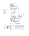
さて図1を参照して、プロセス制御システム10は、データヒストリアン(data historian)12と、各々がディスプレイスクリーン14を有する、ひとつ以上のホストワークステーションまたはコンピュータ13(任意の種類のパソコン、ワークステーションなどであってよい)とに接続されたプロセスコントローラ11を含む。コントローラ11は、入力/出力(I/O)カード26、28を介してフィールド装置15―22にも接続される。データヒストリアン12は、データを記憶するための所望の種類のメモリおよび所望のまたは公知のソフトウェア、ハードウェア、またはファームウェアを有する所望の種類のデータ収集ユニットであってよく、ワークステーション13のうちのひとつとは別個(図1に示されるように)であってもよく、その一部であってもよい。コントローラ11は、例えば、フィッシャー・ローズマウント・システムズ(Fisher Rosemount Systems,Inc)により販売されるDeltaV(商標)コントローラであるが、例えば、イーサネット(登録商標)接続または他の所望の通信ネットワークによってホストコンピュータ13とデータヒストリアン12とに通信可能に接続される。 コントローラ11は、例えば標準的な4−20ミリアンペア装置と関連する所望のハードウェアおよびソフトウェア、および/またはフィールドバスプロトコル、HARTプロトコルのようなスマート通信プロトコルと関連する所望のハードウェアおよびソフトウェアを用いてフィールド装置15−22にも通信可能に接続される。
【0016】
フィールド装置15―22は、センサ、弁、送信器、ポジショナなど、任意の種類の装置であってよく、I/Oカード26、28は、所望の通信プロトコルまたはコントローラプロトコルに従う任意の種類のI/O装置であってよい。図1に示される実施の形態においては、フィールド装置15―18は、アナログ回線によってI/Oカード26と通信する標準的な4―20ミリアンペア装置であり、フィールド装置19―22は、フィールドバスプロトコル通信を用いてディジタルバスによってI/Oカード28と通信する、フィールドバスフィールド装置のようなスマート装置である。一般的に、フィールドバスプロトコルは、フィールド装置を相互接続する2線式ループまたはバスに標準化された物理インタフェースを与える全ディジタルシリアル双方向通信プロトコルである。フィールドバスプロトコルは、事実、プロセス内のフィールド装置のためにローカルエリアネットワークを与え、これによって、プロセス設備(facility)中に分散された位置でプロセス制御機能を実行する(フィールドバスプロトコルにしたがって規定された機能ブロックを用いて)ことができ、これらプロセス制御機能の実行の前後に互いと通信して全体の制御戦略を実行することが出来る。フィールドバスプロトコルは、プロセス制御ネットワークで用いられるために開発された比較的新しい全ディジタル通信プロトコルであるが、このプロトコルは当該技術で公知であり、とりわけ、テキサス洲、オースティンに本部を置く非営利組織のフィールドバスファウンデーションにより出版され、流通され、そこから入手可能である無数の記事、パンフレットおよび仕様書に詳細に説明されていることは理解されるであろう。従って、フィールドバス通信プロトコルの詳細についてはここでは述べられない。当然、フィールド装置15―22は、将来において開発される規格またはプロトコルを含め、他の所望の規格またはプロトコルに従う。
【0017】
コントローラ11は、1個以上のプロセス制御ルーチンを実行するかまたは監督し、そこに記憶されるかまたはそれと関連する制御ループをふくんでよく、装置15―22、ホストコンピュータ13およびデータヒストリアン12と通信を行い所望の方法でプロセスを制御する。尚、本明細書で述べる制御ルーチンまたはエレメントは、所望であれば、様々なコントローラまたは他の装置により実行される一部を有してよい。同様に、プロセス制御システム10内で実行されるべき本明細書で述べる制御ルーチンまたはエレメントは、ソフトウェア、ファームウェア、ハードウェアなどを含め、任意の形をとってよい。本発明の目的のために、プロセス制御エレメントは、例えば、コンピュータ読み取り可能な媒体上に記憶されるルーチン、ブロックまたはモジュールを含め、プロセス制御システムの一部または部分であってよい。制御ルーチンは、モジュール、または、サブルーチン、サブルーチンの一部(コードのラインのような)などのような制御プロシージャの一部であってよく、はしご論理、順次機能チャート、機能ブロック図、もしくは他のソフトウェアプログラミング言語もしくは設計パラダイムを用いてのように、所望のソフトウェアフォーマットで実行されてよい。同様に、制御ルーチンは、例えば、ひとつ以上のEPROM EEPROM、専用集積回路(ASIC)、または他のハードウェアエレメントもしくはファームウェアエレメント内にハードエンコード(hard-coded)されてもよい。 さらに、制御ルーチンは、図形設計ツールまたは他の種類のソフトウェア/ハードウェア/ファームウェアプログラミングツールもしくは設計ツールを含め、何らかの設計ツールを用いて設計されてよい。このように、コントローラ11は、所望の方法で、制御戦略または制御ルーチンを実行するように構成されてよい。
【0018】
ある実施の形態においては、コントローラ11は、一般に機能ブロックと称されるものを用いてある制御戦略を実行する。この戦略においては、各機能ブロックは、全体の制御ルーチンの一部(例えばサブルーチン)であり、他の機能ブロックと(リンクと呼ばれる通信によって)関連して動作してプロセス制御システム10内のプロセス制御ループを実行する。機能ブロックは典型的には、送信器、センサまたは他のプロセスパラメータ測定装置と関連するものとしての入力機能、PID制御、ファジィ論理制御などを実行する制御ルーチンと関連するものとしての制御機能、または、弁のような装置の動作を制御する出力機能のうちのひとつを実行してプロセス制御システム10内で何らかの他の物理的な機能を実行する。当然、ハイブリッド機能ブロックおよび他の種類の機能ブロックが存在する。機能ブロックはコントローラ11内に記憶されてこれにより実行されてよいが、これは典型的には、これらの機能ブロックが標準的な4―20ミリアンペアの装置、およびHART装置のような何らかの種類のスマートフィールド装置のために用いられるかもしくはこれらと関連し、またはフィールドバス装置の場合のようにフィールド装置自体内に記憶されてこれにより実行されてもよい。制御システムについてここでは機能ブロック制御戦略を用いて説明しているが、制御戦略または制御ループもしくは制御モジュールは、はしご論理、順次機能チャートのような他の規約を用いて、または他の所望のプログラミング言語またはプログラミングパラダイムを用いて実行されるか設計されるだろう。
【0019】
図1の拡大されたブロック30に示されるように、コントローラ11は、ルーチン32、34として示される、多くの単一ループ制御ルーチンをふくんでよく、所望であれば、制御ループ36として示されるひとつ以上のアドバンスド制御ループを実行してよい。このようなループ各々は典型的には制御モジュールと称される。単一ループ制御ルーチン32、34はそれぞれ、適切なアナログ入力(AI)機能ブロックおよびアナログ出力(AO)機能ブロックに接続された単一入力/単一出力ファジィ論理制御ブロックおよび単一入力/単一出力PID制御ブロックを用いて信号ループ制御を実行するものとして示され、機能ブロックは、弁のようなプロセス制御装置と関連してもよいし、温度送信器および圧力送信器のような測定装置と関連してもよいし、プロセス制御システム10内の他の装置と関連してもよい。アドバンスド制御ループ36は、多数のAI機能ブロックに通信可能に接続された入力と多数のAO機能ブロックに通信可能に接続された出力とを有するアドバンスド制御ブロック38を含むものとして示されるが、アドバンスド制御ブロック38の入力および出力は他の所望の機能ブロックまたは制御エレメントに接続されて他の種類の入力を受け取り他の種類の制御出力を与えてもよい。アドバンスド制御ブロック38は、制御信号を2個以上のプロセス入力を与えることにより2個以上のプロセス出力を制御するのに用いられる何らかの種類の多入力/多出力制御ブロックであってよい。アドバンスド制御ブロック38はここではモデル予測制御(MPC)ブロックとして説明されているが、アドバンスド制御ブロック38は、ニューラルネットワークモデル化ブロックまたはニューラルネットワーク制御ブロック、多変数ファジィ論理制御ブロック、リアルタイムオプティマイザ(optimizer)ブロックなどのような他の多入力/多出力ブロックであってもよい。アドバンスド制御ブロック38を含む図1に示される機能ブロックはコントローラ11により実行されるか、またはワークステーション13のうちのひとつもしくはフィールド装置19―22のうちのひとつのような他の処理装置内に位置しこれにより実行可能であることを理解されたい。
【0020】
図1に示されるように、ワークステーション13のうちのひとつはアドバンスド制御ブロック生成ルーチン40を含み、このルーチンは、ここで詳細に述べる方法でアドバンスド制御ブロック38を作成し、ダウンロードし、実行するのに用いられる。アドバンスド制御ブロック生成ルーチン40はワークステーション13内のメモリ内に記憶されてプロセッサにより実行されてよいが、このルーチン(またはその一部)は、所望であれば、さらにまたは代替的に、プロセス制御システム10内の他の装置内に記憶されて実行されてよい。一般に、アドバンスド制御ブロック生成ルーチン40は、アドバンスド制御ブロックを作成してこのアドバンスド制御ブロックをプロセス制御システム内に接続する制御ブロック作成ルーチン42と、アドバンスド制御ブロックにより収集されたデータに基づいてプロセスのためのプロセスモデルまたはその一部を作成するプロセスモデル化ルーチン44と、プロセスモデルからアドバンスド制御ブロックのための制御論理パラメータを作成し、これらの制御論理パラメータを、プロセスを制御する際に用いられるためにアドバンスド制御ブロック内に記憶するかダウンロードする制御論理パラメータ作成ルーチン46とを含む。ルーチン42、44、46は、一連の異なるルーチンで構成可能であるが、この一連のルーチンとは、プロセス出力を受け取るように構成される制御入力と制御信号をプロセス入力に与えるように構成される制御出力とを有するアドバンスド制御エレメントを作成する第1のルーチンと、プロセス制御ルーチン(所望の構成ルーチンであってよい)内のアドバンスド制御エレメントをユーザが通信可能に接続できるようにする第2のルーチンと、アドバンスド制御エレメントを用いてプロセス入力の各々に対し励起波形を与える第3のルーチンと、アドバンスド制御エレメントを用いて波形に対するプロセス出力の各々の応答を反映するデータを収集する第4のルーチンと、収集されたデータからプロセスモデルを作成する第5のルーチンと、プロセスモデルからアドバンスド制御論理パラメータを生じさせる第6のルーチンと、アドバンスド制御論理、およびもし必要ならばプロセスモデルをアドバンスド制御エレメント内に配置してアドバンスド制御エレメントがプロセスを制御することができるようにする第7のルーチンとである。
【0021】
さて図2を参照して、フローチャート50は、図1のプロセス制御システム10のようなプロセス制御システム内の、アドバンスド制御ブロック、特にMPC制御ブロックを作成して用いるステップを示す。図2のフローチャート50はMPCブロックまたはモジュールの作成を示しているが、ニューラルネットワークモデル化ブロックまたはニューラルネットワーク制御ブロック、多変数ファジィ論理制御ブロックなどのように多入力/多出力制御ブロックのような他のアドバンスド制御ブロックを作成して用いるために同じステップまたは類似のステップを実行することができる。
【0022】
まず、時間52で、MPCプロシージャを実行する事によりプロセス制御システム10内の制御を向上させるかまたは与えるべく決定が行われる。この決定は、プロセス制御システム10が最初にセットアップされるときかまたは、単一ループ制御ルーチンのような他の制御ルーチンが不十分な制御を与えると発見された後になって行われる。時間52で、オペレータまたは他のユーザがMPCブロック生成ルーチン40を実行して、プロセス制御システム内でMPCモジュールまたは制御ループを作成するステップを開始する。このプロセスの一部として、オペレータは、設計されているMPCブロックの出力が接続されるべきプロセス入力を選択するとともに、設計されているMPCブロックの入力が接続されるべきプロセス出力を選択する。MPCブロックが有する入力および出力の個数は任意であるが、各MPCブロックは一般に、3種の入力を有し、これらは、あるセットポイント(または設定範囲内)で維持されるべきプロセス変数またはプロセスパラメータである制御されたパラメータ入力、プロセスと関連する例えば物理的限界に基づいたある特定の限界値または範囲に制約されるプロセス変数であり、MPCブロックがその入力を制約された範囲または限界値の範囲から外れるように強制してはならない制約された入力、および、変更される場合、制御されたパラメータに対し変更を生じさせるものとして知られているプロセス入力のような他のプロセス変数であるプロセス妨害パラメータ入力である。MPCブロックはプロセス妨害パラメータ入力を用いて、制御されたパラメータ(すなわち制御されたプロセス出力)に対する変化を予知し、これらの変化の影響をそれらが生じる前に制限する。MPCブロックがこれらのエレメントを効果的に制御することができるようにするための制御されている装置または他のプロセスエレメントからのフィードバックのような他の入力もMPCブロックに与えられてよい。同様に、MPCブロックの出力は、制御ループ入力、装置制御入力などを含む所望のプロセス変数または他のプロセス入力を制御するために接続されてよい。MPCブロックを他の制御エレメントに接続することにより生じさせられるルーチンはここではMPCモジュールと称される。ユーザはMPC機能ブロックを作成してよいが、ユーザは、機能ブロックのライブラリのようなメモリからの初期機能ブロックを得て、この機能ブロックを用いるかまたはプロセス制御システムで用いられるこの機能ブロックのインスタンスを作成してよい。同様に、ユーザまたは他のプロバイダは、他の所望の方法で機能ブロックまたは他の制御エレメントを与えてよい。
【0023】
ステップ54で、オペレータは、プロセス制御システム内で通信可能に接続された特定の入力および出力を備えたMPCブロック(モデル予測制御を与えるのに必要な情報をまだ全部有しているわけではない)を有するMPCモジュールを作成し、このブロックまたはモジュールを、MPCモジュールを実行する適切なコントローラまたは他の装置にダウンロードする。このプロセスの一部として、オペレータは、MPCブロックの出力を適切なプロセス入力に通信可能に結合するとともにMPCブロックの入力を適切なプロセス出力に通信可能に結合することにより、MPCブロックを実行するように、プロセス制御システム10を構成する。
【0024】
図3を参照して、MPCブロック56はプロセス58に接続されるものとして示される。MPCブロック56は、3個の入力IN1−IN3 と3個の出力OUT1―OUT3とを有する3x3制御ブロックであり、プロセス58は入力X1−X5と出力Y1−Y6とを含む。当然、MPCブロック56およびプロセス58が含む入力および出力の個数は任意である。MPCブロック56は一般に正方形ブロック、すなわち、同じ個数の入力および出力を有してよいが、この構成は必要でなく、MPCブロック56の有する入力および出力の数は異なっていてよい。図3に示されるように、オペレータは、プロセス出力Y1−Y3をそれぞれMPCブロック入力IN1−IN3に通信可能に接続し、MPCブロック出力OUT1―OUT3をそれぞれプロセス入力X1―X3に通信可能に接続する。当然、プロセス58の入力および出力のうちのいづれかは、プロセス制御システム10と関連する他の制御ルーチン内の他のエレメントに接続されてよい(図3のプロセス入力および出力に接続された点線により示されるように)。一般に、制御入力をプロセス58に与えている(プロセス入力X1―X3に接続された点線により示されるように)MPCブロック56および他のブロックは、なんらかのスイッチを介して接続され、これらのスイッチは図3にボックス59で示される。スイッチ59は、ハードウェアスイッチまたはソフトウェアスイッチであってよいが、所望であれば、フィールドバス機能ブロックのような機能ブロックの異なる入力に異なる制御入力信号を送ることにより与えられてよく、MPCブロック56からの制御信号とPID機能ブロックからのような異なる機能ブロックからの制御信号とを受け取る機能ブロックのモードに基づいて、これらの信号の間で選択を行うことができる。
【0025】
当然、オペレータは所望の方法で、MPCブロック56をプロセス58に接続可能であり、一般に、オペレータがプロセス制御システム10内の単一制御ルーチンのような他の制御ループを作成するのに用いるのと同じ制御構成プログラムまたは設計プログラムを用いるだろう。例えば、オペレータは、所望の図形プログラミングルーチンを用いて、MPCブロック56とプロセス入力出力との間の接続を指定してもよい。このようにして、MPCブロック56は、他の制御ブロック、エレメント、またはルーチンと同じ方法で支援されてよく、これは、MPCブロック56の構成および接続と、システム10内の他のブロックの構成、接続および支援と同じような制御システム10内のそのブロックの支援とを行う。ある実施の形態においては、制御システム10内の他のブロックと同様にMPCブロック56は、フィールドバス機能ブロックと同じであるかまたはそれと類似であるように設計された機能ブロックである。この実施の形態においては、MPCブロック56は、フィールドバスプロトコルにおいて特定されるか与えられた通り、同じまたは類似の種類の入力、出力などを有してよく、例えば、フィールドバスプロトコルにより特定されたものと同じであるかまたは類似の通信リンクを用いて、コントローラ11により実行可能である。プロセス制御ルーチンおよびそのエレメントを図形で作成する方法は、 「プロセス制御環境を構成するためのシステム"System for Configuring a Process Control Environment"」と題されたドゥーブらの米国特許第5、838、563号に記載され、この特許を本明細書において引用により援用する。 当然、他の種類の機能ブロックを用いるかまたはプロセス制御構成パラダイム内の他のルーチン、サブルーチンまたは制御エレメントを用いるものを含め、他の制御ループまたは制御モジュール設計戦略も同様に用いられてよい。
【0026】
フィールドバス機能ブロックパラダイムが与えるブロックような、機能ブロックの相互接続に基づいた制御システムを用いるとき、MPCブロック56はプロセス制御ルーチン内の他の機能ブロックに直接接続可能である。例えば、MPCブロック56は、MPCブロック56の制御出力を、制御されている装置と関連する出力ブロック(AOブロックのような)に直接接続することにより弁などの制御装置に接続されてよい。同様に、MPCブロック56は、他の制御機能ブロックの入力ような、他の制御ループ内の機能ブロックに制御信号を与えて、これらの制御ループの動作を予知するかオーバーライドしてもよい。
【0027】
図4A、4Bは、例えば、フィールドバスタイプのMPC機能ブロック60を示し、これは、プロセス制御システム内の他のフィールドバスタイプの機能ブロックに接続されて、単一ループ制御ルーチンにより実行される既存の多変数戦略を調整する。特に、MPC機能ブロック60は、操作されている弁と関連するAOブロック62のRCAS IN(リモートカスケード)入力に接続された第一の出力OUT1と、PID機能ブロック64のRCAS IN(リモートカスケード)入力に接続された第2の出力OUT2とを有する。さらに、MPCブロック60は、AI機能ブロック66から送られた第一の入力I1(制御されたパラメータ入力)と、AI機能ブロック68(図4B)から送られた第一の入力I2(制御されたパラメータ入力)と、AI機能ブロック70から送られた第3の入力I3(妨害パラメータ入力)とを有する。AI機能ブロック66、68、70は、センサのようなフィールド装置により測定され、送信器または他の装置により制御ルーチンに送信される信号と関連し、これを与えてよい。MPCブロック60は、MPCブロック60により機能ブロック62、64に送られる制御信号の影響を決定する際に用いられるAO機能ブロック62およびPID機能ブロック64のリモートカスケード出力(RCAS OUT)から、入力BKCAL IN1およびBKCAL IN2(バック較正入力)で、フィードバックを受け取る。AI機能ブロック66の出力はPID機能ブロック72の入力に与えられ、PID機能ブロック72は、AO機能ブロック62のカスケード入力(CAS IN)に制御信号を与え、PID機能ブロック72のBKCAL IN入力でAO機能ブロック62の出力OUTからのフィードバック信号を受信し、それにより、プロセスの通常の動作の間に、すなわち、MPC動作なしに、操作された値を制御する。同様に、AO機能ブロック68は、その出力(プロセス出力)をPID機能ブロック74の自動入力に送り、PID機能ブロック74は、制御信号をPID機能ブロック64のカスケード入力に与える。PID機能ブロック74は、機能ブロック74のBKCAL IN入力でPID機能ブロック64からフィードバック信号も受信する。図4A、4B(図5と同様に)の機能ブロックの入力および出力は、フィールドバスプロトコルの場合と同じように規定され、フィールドバスプロトコルにより与えられた規定および構成に従って動作する。
【0028】
理解されることであるが、機能ブロック66、72、62は、第1の単一ループ制御ルーチンを形成し、機能ブロック68、74、64は第2の単一ループ制御ルーチンを形成し、これら両方は、プロセスの通常動作または自動動作の間に動作されてよい。しかしながら、MPCブロック60は、AO機能ブロック62およびPID機能ブロック64のリモートカスケード入力に制御入力与えることにより、PID機能ブロック64と関連するループの制御だけでなく、AO機能ブロック(および関連の装置)の制御を引き受けてよく、これにより、これらの機能ブロックは(自動モードの代わりに)リモートモードで動作するようになり、従って、自動入力のかわりにリモート入力で制御入力を用いて動作する。リモートモードで動作するとき、機能ブロック62、64は、それぞれPID機能ブロック72、74の入力を無視する。このように、MPCブロック60はブロック62、64に接続されてその制御を与えてもよいが、スイッチオン・オフしてもよい。MPC機能ブロック60により制御されていないときは、ブロック62、64は、単一ループ制御戦略に従って、それぞれブロック72、74により依然として制御されている。
【0029】
同様に、図5は、プロセス制御ルーチン内で接続されて単一ループルーチンを調整するMPC機能ブロック80を示す。特に、MPC機能ブロック80は、AI機能ブロック82、84からの制御されたパラメータ入力とAI機能ブロック86からの妨害パラメータ入力とを受け取る。MPC機能ブロック80は、操作された値と関連するAO機能ブロック90に制御出力を与え、制御ループ94内のPID機能ブロック92のカスケード入力(CAS IN)にセットポイント出力を与える。AO機能ブロック90およびPID機能ブロック92は、MPC機能ブロック80のバック(back)較正入力に、バック較正出力を与える。制御ループ94は、AI機能ブロック96も含み、AI機能ブロック96は、PID機能ブロック92の自動入力に制御パラメータ入力(すなわちプロセス出力)を与え、PID機能ブロック92ついで、例えば、異なる弁または装置と関連するAO機能ブロック98に制御出力を与える。AO機能ブロック98は、PID機能ブロック92のバック較正入力にフィードバックを与える。図5の構成において、MPC機能ブロック80は、AO機能ブロック90と関連する弁を直接制御し、そのループのセットポイントを操作することによりループ94の動作を制御する。しかしながら、ループ94は、MPC機能ブロック80が動作しているときに動作し続ける。そのようなものとして、MPC機能ブロック80は、AO機能ブロック98と関連する装置を間接的に制御するが、制御ループ94を直接制御する。当然、MPCブロックは他の所望の方法でプロセス制御ルーチン内で接続されて、制御装置または他の制御エレメントを直接的にまたは間接的に制御する。さらに、図形プログラミング技術または非図形プログラミング技術を含め、なんらかの技術を用いて制御ルーチンまたはモジュールが生じさせられてよい。
【0030】
このように、理解されるだろうが、図3においてMPCブロック56の出力が接続されるプロセス入力X1―X3は、既存の制御戦略内で規定された制御ループへの入力、またはプロセスに接続された弁または他の装置への入力を含め、所望のプロセス入力であってよい。同様に、MPCブロック56の入力に接続されたプロセス出力Y1-Y3は、弁または他のセンサの出力、AO機能ブロックまたはAI機能ブロックの出力、または他の制御エレメントもしくは制御ルーチンの出力を含め、所望のプロセス出力であってよい。
【0031】
図2のステップ54を再び参照して、いったん、オペレータが、それぞれ所望のプロセス出力および入力に接続された入力および出力を有する初期のMPCブロックを含む制御モジュールを作成すると、初期のMPCブロックを有する制御モジュールは、コントローラ11またはワークステーション13のうちのひとつのような適切な装置にダウンロードされて、実行される。つぎに、ステップ99で、オペレータは、初期MPCブロックに、公知の方法でプロセスを励起し始めるように命令し、プロセスが励起されている間にプロセス入力データおよびプロセス出力データを収集するように命令する。
【0032】
図3に示されるように、初期MPCブロック56は、データ収集ユニット100と、波形ジェネレータ101と、汎用制御論理102と、制御パラメータ103およびプロセスモデル104を記憶するための記憶装置とを含む。汎用論理102は、例えば、ある特定のインスタンスにおいて動作するか制御を実行することができるように係数または他の制御パラメータを必要とする汎用MPCルーチンであってよい。場合によっては、汎用論理102は、プロセスを制御するために、制御されているそのプロセスのためのプロセスモデルを必要としていてもよい。例えば、コントローラ11にダウンロードされた後、初期のMPCブロック56は、MPC作成ルーチン42によって、MPCブロック56の作成の次のフェーズを開始するように命令され、このフェーズにおいては、データは、プロセスモデルを作成する際に用いられるプロセス出力の各々のために収集される。特に、オペレータによりそうするように命令されたとき(または他の所望の時間で)、MPCブロック56の波形ジェネレータ101は、その出力OUT1―OUT3で一連の波形を生成し始め、これにより、プロセス入力X1― X3の各々に励起波形を与える。所望であれば、これらの波形は、ユーザワークステーション13内のソフトウェアにより波形ジェネレータ101に与えられてよいが、好ましくは、波形ジェネレータ101により作成される。波形ジェネレータ101により生成された波形は好ましくは、プロセスの通常動作の間に予測される異なる範囲の入力にわたってプロセスが動作するように設計される。MPC制御ルーチンのためのプロセスモデルを作成するために、波形ジェネレータ101は、プロセス入力X1―X3の各々に、一連の異なる組のパルスを送ってよく、パルスは組ごとに同じ振幅を有するが擬似ランダム長を有し、異なる組のパルスは異なる振幅を有する。このような一連の組のパルスは、異なるプロセス入力X1―X3の各々のために作成され、ついで、1個ずつ、順次これらの入力の各々に送られてよい。この時間において、MPCブロック56内のデータ収集ユニット100は、波形ジェネレータ101により生成された波形の各々に対するプロセス出力Y1―Y3の応答を示すデータを収集するかまたはこのデータの収集を調整し、生成されている励起波形に関するデータを収集するかまたは収集を調整してもよい。このデータは、MPCブロック56内に記憶されてよいが、このましくは、データヒストリアン12に自動的に送られて記憶され、および/またはワークステーション13に送られて、ここでこのデータは、ディスプレイスクリーン14上に表示されてよい。
【0033】
このように、なんらかのアドバンスド制御論理(まだ完全には生成されていない)を用いてプロセス58を制御しようとするかわりに、MPCブロック56はまず、プロセス58に一組の励起波形を与え、これらの励起波形に対するプロセス58の応答を測定する。当然、波形ジェネレータ101により生成された励起波形は、アドバンスド制御ルーチンのための作成制御論理パラメータにとって有用なプロセスモデルを作成するために生じさせられた所望の波形であってよい。この例においては、波形ジェネレータ101は、モデル予測コントローラのためのプロセスモデルを作成するのに有用であると知られている一組の波形を生成し、これらの波形は、この目的のために、現在知られているかまたは将来において開発されるなんらかの形をとってよい。モデル予測制御のためのプロセスモデルを作成するべくデータを収集する目的でプロセスを励起するのに用いられる波形は周知であるので、ここでは詳細に述べない。同様に、ニューラルネットワーク、多変数ファジイ論理などの制御ルーチンのような他のアドバンスド制御(モデル化を含む)ルーチンのためのプロセスモデルを作成する際に用いられる波形ジェネレータ101により、他の種類のまたは所望の種類の波形が生成されてよい。
【0034】
尚、波形ジェネレータ101は、所望の形をとってよく、例えば、ハードウェア、ソフトウェアまたはその両方の組み合わせにおいて実行されてよい。ソフトウェアで実行される場合、波形ジェネレータ101は、所望の波形を生成するのに用いられるアルゴリズムを記憶してよいし、生成されるべき波形のディジタル表現を記憶してよいし、または他のルーチンまたは記憶されたデータを用いてそのような波形を作成してもよい。ハードウェアで実行されるときは、波形ジェネレータ101は、例えば、発振器または矩形波ジェネレータの形をとってもよい。所望であれば、オペレータは、プロセスのほぼ正確な応答時間、プロセス入力に送られるべき波形の振幅のステップサイズなどのような、波形を設計するのに必要なパラメータを入力するように頼まれるかもしれない。MPCブロック56が最初に作成されるかまたはオペレータがMPCブロック56にプロセスをアップセットするか励起し、プロセスデータを収集するのを開始するように命令するときに、この情報を得るためにオペレータは促されてよい。好ましい実施の形態において、データ収集ユニット100は、確実に完全かつ正確なプロセスモデルが作成されるように、オペレータが入力する応答時間の3倍かまたは5倍の時間において励起波形の各々に応答してデータを収集する(またはデータの収集を確実にする)。しかしながら、データが集められる時間量は任意である。
【0035】
いづれにせよ、MPCブロック56は好ましくは、波形ジェネレータ101がプロセス入力X1―X3の各々に対し必要な励起波形を全て送り終えてしまうまで、そしてデータ収集ユニット100がプロセス出力Y1―Y3のためのデータを収集してしまうまで、動作する。当然、MPCブロック56の動作は、このデータ収集プロセスの間に所望であればまたは必要であれば中断されてもよい。
【0036】
図6を参照して、制御論理生成ルーチン40によりディスプレイ14のうちのひとつの上にオペレータに提示可能なスクリーンディスプレイ118により、オペレータはアドバンスド制御ブロックを生成する異なるステップを実行できる。特に、スクリーンディスプレイ118は、データディスプレイ領域120と、アドバンスド制御ブロック生成ルーチン40の様々な部分を開始するのに用いられる3個のボタン122、123、124を含む。開始テストボタン122により、オペレータは、初期のMPCブロック56にプロセス58に励起信号を送らせて、データヒストリアン12に対し送る入力データおよび出力データを収集させる。ボタン122は、例えば、励起ルーチンを実行するために残っている時間、すなわちMPCブロック56が励起波形の全てを生成してこれらの波形に応答して生成されたプロセスデータを収集するのにかかる時間を示す。ボタン122を押す前に、オペレータは、プロセスが入力に応答するのにかかる典型的な時間を示す応答時間を入力して、励起波形を生成するためにMPCブロック56により用いられるステップサイズを示すか指定してよく、このデータはMPCブロック56の波形ジェネレータ101に与えられてよい。ボタン122を押した後、MPCブロック56により収集されたデータはデータディスプレイ領域120上で表示されてもよく、所望であれば、ユーザは、プロセスモデルを作成するのに用いられてはいけないデータにフラグをつけてもよい。尚、データ収集ユニット100は、確実にこのデータをデータヒストリアン12または他の記憶装置に送られ記憶されることによりデータを収集してもよい。
【0037】
次に、図2に示されるように、ステップ125で、オペレータは、あるポイントで、プロセスモデル化ルーチン44を実行することによりMPCブロックを作成する次のフェーズを実行することを決定してよく、プロセスモデル化ルーチン44は、データヒストリアン12からの収集されたデータにアクセスして、公知のプロセスモデル生成ルーチンを実行して、収集されたデータからプロセスモデルを作成する。一般的に、オペレータは、図6のスクリーンディスプレイ上の生成制御ボタン123を選択することでこのフェーズを開始してよい。
【0038】
所望であれば、プロセス制御ルーチン44は、収集されたデータに関してデータふるい分けプロシージャを実行してもよい。このデータふるい分けプロシージャは、アウトライアー(outlier)の収集データ、および他の明らかなエラーデータを検査し、収集されたデータと関連する状態値および限界値のような、収集されたデータと関連する他の値を検査して、そのデータが不良または不適当な状態を有する機能ブロックにより生成されたものかどうか、そのデータが限界値にあったかどうか、そのデータが、機能ブロックまたは他のエレメントが不適当なモードであったときに生成されたものであるかどうか、またはそのデータが、異常なプロセス状況下または望ましくないプロセス状況下でなんらかの方法で生成されたものであるかどうか決定する。例えば、フィールドバス通信プロトコルにおいては、機能ブロックにより生成されたデータは、データヒストリアン12内にデータとともに記憶可能であり、データをふるいにかけるために用いられる状態、限界値、およびモード指標も含む。所望であれば、データふるい分けルーチンは、図6のデータディスプレイ領域120上でオペレータに収集されたデータを示してもよく、このルーチンによって、例えば、プロセス状況のオペレータの知識に基づいてこのデータを強調表示するかまたは識別することにより、オペレータは、ふるい落とされるすなわち除かれるべきデータに印を付けることができる。このように、プロセス58がオフラインであったとき、プロセス58が適切に制御されていなかったとき、プロセス58が修理中であったとき、プロセス58内のセンサまたは他の装置が故障していたか取りかえ中などにMPCブロック56により収集されたデータは、選別されて、プロセスモデルを作成するために用いられるべきデータから除かれてよい。
【0039】
図6に示されるように、ディスプレイ領域120内のトレンド(trend)は、トレンドプロットとしてMPC入力および出力を含むものとして表示されてよい。プロットは、これらの入力および出力の値に基づいて自動基準化される。また、表示されるプロットの部分の時間フレームは好ましくは、指定された応答時間の2倍であるだろう。スライダバー126を用いて、時間ウインドウは、過去2日のような以前の時間にさかのぼった値を示すように変更されてもよい。プラント動作上で良好なデータを収集できるように、自動化テスト機能を用いてもよい。開始テストボタン122を選択することにより、MPCブロックにより操作されるプロセス入力、指定された応答時間にわたって、MPCブロックにより操作されるプロセス入力は、擬似ランダムシーケンスにおける指定されたステップサイズにより衝突される(bumped)。また、開始テストボタン122が選択されたとき、データディスプレイ上の開始および終了分割バーは、自動化テストの開始および終了に印をつけるように自動的に設定され、MPCブロック56は、プロセス58に、励起波形のような出力信号の擬似ランダムシーケンスを与えることにより、操作された出力の制御を引き受ける。
【0040】
ディスプレイ領域120内の時間バーまたはデータウインドウは、プロセスモデルを作成するために用いられるデータを選択するのに用いられてもよい。オペレータは、分割バーのうちのひとつを選択して、それを所望の開始時間および終了時間にドラッグ(drag)して、プロセスモデルを識別するために考慮される時間フレームを変更する。開始バーおよび終了バー間の時間の一部が通常のプラント動作を表していなければ、ユーザまたはオペレータは、プロセスモデル識別プロセスの間に無視されるべきデータ値を選択するために時間のこの部分を捕らえる。これに応答して、選択された領域は、より暗い背景色で示され、プロセスモデルを作成するとときに自動的に除かれる。
【0041】
データをふるいにかけた後、プロセスモデルルーチン44は、選別されたデータからプロセスモデルを作成する。上で述べたように、プロセスモデル化ルーチン44は、所望のまたは公知のタイプのプロセスモデル化解析を行って、収集されふるいにかけられたデータからプロセスモデルを作成してよく、作成されたプロセスモデルは、数学アルゴリズム、一連の応答曲線などのような任意の形をとってよい。
【0042】
プロセスモデル化ルーチン44がプロセスモデルを決定する際に問題を有しているならば、その問題の指標は、図6に示されるようなユーザディスプレイの状態領域において反映されてもよい。ひとつの問題が示されているが、これは、プロセスモデルを識別するかまたは作成するのに十分なサンプルがないということである。 規定された構成のためには最低限XXX個のサンプルが必要であるとメッセージがでている。データファイルはXXX個のサンプルだけを含むだけであるというメッセージがこの問題をオペレータに知らせるために生成されてよい。検出されるおそれのある別の問題としては、プロセス入力について十分な励起が生じなかったということである。このような問題が生じたとき、この影響に対するメッセージ、TagX、TagYなどの信号タグ名を識別するもの、および励起量に対する最小変更をオペレータに与えることが出来る。
【0043】
所望の場合、そして、成功したモデルが識別されなかった状況では、ユーザは、プロセスモデル化が行われている期間の時間フレームを変更してもよいし、または、プロセスモデル化ルーチン44で用いられているデータが有効であるようにプロセス入力を変更してもよい。識別されるプロセスモデルは、後にアクセスできるように所望のデータベース内に自動的にセーブされてよい。熟練したユーザは、識別されたプロセスモデルを調べるか編集したいと思うだろう。図6のスクリーン上のアドバンスドボタン124を選択することにより、選択されたモデルおよび現在のMPC機能ブロック構成からMPCコントローラを生成することまたはMPC制御論理を作成するのに用いられるべき新たなモデルとしての結果として生じるモデルをセーブすることの選択肢を与えられる。生成コントローラオプションが選択されると、ユーザには、編集されているMPCモジュールにおけるMPCブロックのために前にセーブされたモデルをユーザが選択し得るダイアログが提示可能である。編集オプションを選択することにより、ユーザには、問題のMPCモジュールのために作成されたモデルのリストが提示可能である。モデルを選択した後、ユーザは、プロセスステップ応答のオーバービューを表示するスクリーンまたは、後に説明する他のスクリーンを見て、プロセスステップ応答を編集して新たなまたは変更されたモジュールを作成する。
【0044】
プロセスのあるポイントにおいて、論理パラメータ作成ルーチン46は、初期MPCブロック56の汎用論理102が必要なパラメータ(MPCブロック56内の変数内に記憶されるべき)を作成するために実行され、モデル予測制御を実行してよい。これらの制御パラメータは、例えば、MPC論理のための行列または他のMPC係数、チューニングパラメータ、ニューラルネットワークパラメータ(ニューラルネットワークのための)、倍率(多変数ファジイ論理のための)または他の所望のパラメータであってよく、通常は、生成されたプロセスモデルに基づいて決定される。論理パラメータ作成ルーチン46は、プロセスモデルからパラメータを作成するための所望のプロシージャまたは公知のプロシージャを実行してもよい。一般に、このプロセスは、行列フォーマットでプロセスモデルを反転することを伴う。しかしながら、他の所望の論理パラメータ作成ルーチンも用いることができる。プロセスのために収集されたデータからプロセスモデルを作成し、そのプロセスモデルからMPCパラメータまたは他の制御論理パラメータを生成する詳細は、当該技術で公知であるので、これらのプロシージャはさらにここでは述べない。尚、しかしながら、オペレータがMPCブロック56のための制御論理パラメータの作成に関するなんらかの入力を有してもよい。事実、オペレータは、MPCコントローラを作成するのに典型的には用いられるある変数の値を指定する能力を要求されるかまたは与えられてよい。例えば、オペレータが指定してよいのは、MPCブロックへの制約された入力の各々のセットポイントおよび限界値、制御変更を行うべき期間の時間フレーム、すなわち、セットポイント軌跡(trajectory)フィルタおよびこのフィルタと関連する時定数、MPC出力またはプロセス出力の最大の動きまたは最小の動き(速度限界値)、制御されたパラメータのいづれかが統合的に応答するかどうか、MPC最適ファクタ、MPC変数またはMPCチューニングパラメータ、MPCブロックの水平線(horizon)、すなわち所望の状態になるように制御するために順方向計算のステップがいくつ実行されるべきであるか、MPCブロック56の入力および出力の各々に対するエンジニアリングユニット範囲、操作された変数目標値のうちのどれが、制約条件のうちのひとつが違反されたときに緩められることを許可されているかまたは実現されないか、MPCブロック入力および出力の各々の記述および/または名前、設定可能な最適変数の値、MPCブロックの積極性または頑強性に関する変数の値などである。所望であれば、制御論理生成ルーチン46は、これらの変数またはセッティングのいくぶんかまたは全てのデフォルト値を記憶し、これらのデフォルト値を用いてMPC論理を作成する。しかしながら、オペレータまたは他のユーザは、ユーザディスプレイ14を介してこれらのセッティングを変更することができる。
【0045】
いづれにせよ、MPC論理パラメータ作成ルーチン46はこの情報、および、MPC係数のようなMPC(または他の)制御論理パラメータを作成するのに必要な他の情報を用いて実行される。スクリーンディスプレイ118上の生成制御ボタン123は、プロセスモデルおよび制御論理パラメータの作成が成功したかどうかを示してよい。
【0046】
MPC制御論理パラメータが作成された後、図2のステップ128で、MPC制御論理パラメータまたはMPC係数がプロセスシミュレーションブロックを用いてテストされてもよい。このシミュレーションブロックは一般に、プロセスのために作成されたプロセスモデルから作成されてよく、ここで説明されるようにテスト環境内でMPCブロックに接続されて、作成されたMPC制御論理がプロセスの通常動作の範囲にわたって申し分なく動作するかどうかテストする。MPC論理が満足いくものでなければ、ステップ54、99、および125のいづれかまたは全てが繰り返されて異なるMPC制御論理を作成してよい。しかしながら、もしもMPC制御論理が満足いくものであれば、ステプ130で、MPC制御論理パラメータおよびプロセスモデルは、MPCブロック56にダウンロードされてパラメータ記憶装置103およびプロセスモデル記憶装置104内に記憶され、プロセス58を制御するのに用いられる。このように、MPC制御論理が必要なパラメータは、MPCブロック56に与えられ、そこに格納され、MPCブロック56は、MPC制御論理102にしたがってプロセス内で動作するかまたは制御を実際に実行するように委託される。当然、所望であれば、必要なパラメータと共に実際のMPC論理102はワークステーション13で作成されて、MPCブロック16にダウンロード可能である。
【0047】
いったん、コントローラ11によりダウンロードされ実行されると、MPCブロック56を有するMPCモジュールまたはループは、制御ルーチン内の他のブロックまたはエレメントと同じ方法で機能を報告することを行ってよい。なぜなら、上で述べたように、MPCブロック56およびこのブロックを含む制御モジュールは、プロセス制御システム10内の他の制御ブロックと同じプログラミングパラダイムを用いて設計されるからである。ある実施の形態においては、MPCブロックまたはモジュールは、それと関連する図形ビューを有してよく、これは、例えば、ワークステーション13のうちのひとつのうちのディスプレイスクリーン14のうちのひとつによって、ユーザまたはオペレータに表示可能であり、これらのビューは、MPC制御モジュール内のブロックと関連するデータを予約し、このデータを予め規定されたまたは指定された方法で表示する。
【0048】
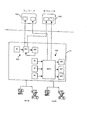
図7を参照して、例えば、図1のプロセス制御システム10の一部分が示され、ディスプレイ14Aおよび14Bと装置15−22とに通信リンク(具体的には示されていない)を介して結合されたコントローラ11をふくんでいる。コントローラ11内で、MPCモジュール132は、一組のAI機能ブロックから入力を受け取り、一組のAO機能ブロックに出力を与えるAPC機能ブロックを有するものとして示され、単一のループ制御ルーチン134は、AO機能ブロックを制御するために、AI機能ブロックからの入力を受け取るPIDブロックを含むものとして示される。
【0049】
オペレータのビューおよびエンジニアのビューのような、これら2個の制御モジュールの動作の異なるビューが、ディスプレイスクリーン14Aおよび14B上で図形で示される。特に、ディスプレイスクリーン14A上のエンジニアのビューは、エンジニアがこれらのループに関する情報にアクセスしてこれらのループを操作できるように作成されるループ134の図形表現だけでなくループ132の動作の図形表現も含む。同様に、ループ134の図形表現だけでなくループ132の動作の図形表現を有するオペレータのビューがディスプレイスクリーン14B上に与えられ、これにより、オペレータは、これらのループに関する情報にアクセスし、これらのループを操作できる。しかしながら、オペレータのビュー内で与えられた情報は、エンジニアのビュー内の情報とは異なっていてよく、ループ132、134と対話するようにこれらのビューにより与えられたケイパビリティは異なっていてよい。例えば、オペレータのビューは、オペレータがセットポイントを変更して、制限された機能を実行するこのとができるようにするだけであり、エンジニアのビューは、ユーザが、ユーザがループのセットアップに対し変更を加えたり、機能ブロック内のプログラミングに変更を加えることができるようにする。
【0050】
これらの異なるビューは、「プロセス制御プログラミングのための均一制御テンプレート生成システムおよび方法"Uniform Control Template Generating System and Method for Process Control Programming"」と題されたBlevinsへの米国特許第5、594、858号(本明細書において引用により援用される)で述べられるテンプレートに対して開示されたものと類似の方法で機能ブロックと関連して作成されてよい。しかしながら、これらのブロックを用いて作成されるMPCブロックおよびモジュールは、プロセス制御システム10内の他のブロック、ルーチンまたはエレメントとして同じ種類の図形支援または報告支援を与えることができ、なぜなら、これは、MPCブロックが他の制御ブロックと同じプログラミング戦略を用いてオンラインで作成されたからであるということを理解されたい。この機能により、オペレータ、技術者、エンジニアなどがMPC制御モジュールまたはMPCブロック内で起こっているものを見れるよう特別なプログラミングを与える必要がなくなる。
【0051】
所望であれば、MPCモジュール132は、予め規定されたビューまたはディスプレイによって、ユーザに所望の情報を報告してもよいし、ユーザまたはオペレータが所望の行為を行えるようにしてもよい。例えば、ユーザにはあるスクリーンが与えられ、これは、MPCモジュール132により生成されたまたはそれと関連する警報(アラーム)を示し、制御されたパラメータ、制約されたパラメータ、および妨害パラメータ(制御されたパラメータおよび制約されたパラメータの計画された値を示してよい)のプロットを与え、ユーザまたはオペレータが、例えば、モードパラメータ(MPCモジュール132が例えばフィールドバスプロトコルを用いて作成されるとき)を用いてMPCモジュール132の実行を制御できるようにし、セットポイント、制約条件、および制御された入出力または制約された入出力の値を数値的にまたはバーグラフで示し、MPCセットポイントまたはMPC目標値を変更できるようにし、例えば、入力が不良であるのか、不確実であるのかまたは制限されているかを示すためにMPC入力の状態を示し、または他の所望のデータを示すか所望の機能を行うものである。
【0052】
MPC制御モジュール内のMPCブロックにMPC制御論理をダウンロードすることに加えて、図2のステップ135で、作成された論理を有するMPC論理またはMPCブロックは、例えば、MPCブロックの使用方法をユーザに訓練し、MPCブロックをテストするために、ひとつ以上のシミュレーション環境で用いるためにワークステーションに送られてもよい。このようなシミュレーション環境は、1999年5月6日に出願された「単一コンピュータ上で分散プロセス制御システム機能性を統合すること"(Integrating Distributed Process Control System Functionality on a Single Computer)"」と題された米国仮出願番号60/132,780に詳細に記載されるシステムを用いて与えられてよいが、この仮出願は、本発明の譲受人に譲渡され、その開示を本明細書において引用により援用される。さて、図8を参照して、シミュレーション構成149は、シミュレーション環境において、作成されてプロセスシミュレーションブロック152に接続されたMPCブロック150を含む。シミュレーション構成149は、図2のステップ128で、例えば、完成したMPCブロックをテストするのに用いられて、そのために作成されたプロセスを十分に制御するかどうか決定してもよいし、または、図2のステップ135で、例えば、MPCブロックを用いて訓練または他のテスト環境を与えるのに用いられてもよい。図8のMPCブロック150は3個の入力IN1−IN3と3個の出力OUT1−OUT3とを有するものとして示され、3個入力X1−X3と3個52に接続され、出力Y1―Y3は、MPCブロック150の入力IN1−IN3にそれぞれ接続される。シミュレーションブロック152は、図8のブロック154により示されるように、図2のステップ125で作成されたプロセスモデルを用いてそれのためのMPCブロック150が作成されたプロセスをシミュレートしてもよい。この場合、図2のステップ125で作成されたプロセスモデルはシミュレーションブロック152内に記憶されて、そのプロセスモデルとMPCブロック150から受け取った入力とに基づいて、プロセスの応答をシミュレートするのに用いられてよい。代替的には、シミュレーションブロック152は、図8のブロック156により示されるように、ステップ152で生成されたプロセスモデルに対して変更されるプロセスモデルから作成されてもよい。この場合、ステップ125で作成されたプロセスモデルは、例えば、プロセスになされた物理的な変更、プロセス内の機器のエージングなどにより引き起こされたプロセスに対する変更をシミュレートするために変更されてよい。所望であれば、図2のブロック125で作成されたプロセスモデルは、このブロックが最初にMPCブロック150を作成するのに用いられるプロセスと一致しないプロセスを制御するのに用いられるときに、MPCブロック150の動作をテストするために様々な方法で変更されてよい。このように、所望であれば、ブロック156が与えた変更されたプロセスモデルは、シミュレーションブロック152内で用いられて、プロセスが変化したりMPC制御論理に一致しないときにMPCブロックが与える制御の範囲を決定し、これにより、ユーザは、長期間にわたって動作するかまたはプロセス変化が生じたプロセスを制御するのに良好なMPCブロックを設計することができる。
【0053】
変更されたプロセスを生成するには、ユーザまたはオペレータはルーチンを実行し、ステップ125で作成されたプロセスモデルまたは、5x5MPCブロック150のために図9のスクリーンに示されるもののような、関連するプロセス入力/出力応答曲線の組を見て、これらの応答曲線のうちの変更すべきひとつを選択する。選択された応答曲線(オーバーヘッド%C3H6対リボイラーオイル流量と示される)はさらに、図10に示されるようなさらなるスクリーンによって表示されるか操作されてよい。図10に示されるように、ユーザまたはオペレータは、応答曲線をインポート(取り入れ)するか消去し、FIR応答を加え、不動作時間およびゲインなどの応答パラメータを変更し、新たなスタートポイントまたは終了ポイントを選択し、曲線のポイントの値を変更し、曲線に対し様々な勾配をつけ、曲線をスケールして、それにより、変更された応答曲線、したがって、変更されたプロセスモデルを作成する。当然、ユーザまたはオペレータは、他の方法でプロセスモデルを部分的に変更(修正)するか変更する。ユーザは、プロセスモデル150を作成するか編集してもよく、このようなモデルからプロセスシミュレーションブロックまたはエレメント152を作成してもよく、プロセスシミュレーションブロック152をMPCブロック150に通信可能に接続してもよく、左手のプロセッサ13において、または他の所望のシミュレーション環境においてもしくはプロセス環境において、図1に示されるルーチン153のようなルーチンを用いて、接続されたループを実行してもよい。
【0054】
さて図11を参照して、実際のプロセス174に接続されたMPCブロック172を有するものとしてさらなる制御ループ170が示される。この場合、MPCブロック172の3個の出力OUT1−OUT3は、プロセス174のために作成されたプロセスモデル178に基づいたシミュレートされたプロセスブロック176の3個の入力X1SIM―X3SIMだけでなくプロセス174の3個のプロセス入力X1―X3に接続されされる。この構成においては、MPCブロック172は、実行時間においてプロセス174を制御し、シミュレートされたプロセスブロック176も制御するが、このブロック176は、例えば、図1のワークステーション13のうちのひとつにおいてまたは他のコントローラもしくは装置において実行されてよく、シミュレートされた出力Y1SIM―Y3SIMを生成する。このようなシステムにおいては、シミュレートされたプロセスブロック176の出力Y1SIM―Y3SIMと、実際のプロセス174の出力Y1―Y3とは比較され、プロセス出力Y1―Y3がシミュレートされた出力Y1SIM―Y3SIMとは非常に異なるかどうか、したがって、実際のプロセス174とMPCブロック172がそこからが作成されたプロセスモデル178とに間に不一致があるかどうか決定する。不一致がある場合、別のMPCブロック172を作成するかまたはプロセス174を制御する際にMPCブロック172が用いる論理パラメータまたはモデルを再生する必要がある。
【0055】
また、もしも何らかの理由でプロセス174の出力Y1―Y3のうちのひとつが、例えば、この出力を測定するセンサの誤動作が原因でエラーになった場合、シミュレートされたプロセスブロック176からの対応するシミュレートされた出力は、図11の点線で示されるようにMPCブロック172の適切な入力に与えられてよく、これにより、故障したセンサまたは装置が取りかえられるか修理されるまで、MPCブロック172は実際のプロセス174の良好な制御を与えることができる。このようにして、実際のプロセス出力の各々のために、仮想プロセス出力が、シミュレートされたプロセスブロック176により作成されてよいし、これらの仮想出力のうちのひとつ以上は、対応する実際のプロセス出力に欠陥があるかまたは使用できないときにMPCブロック172への入力として使用されてよい。例えば、深夜に、プロセス出力Y1―Y3のうちのひとつを測定するセンサが誤動作した場合、ユーザまたはオペレータは、修理者が故障したセンサを取りかえるか修理する次の日まで、MPCブロック172がプロセス174の十分な制御を与えることができるように、MPCブロック172の適切な入力に対応する仮想出力を単に接続すればよい。シミュレートされたプロセスブロック176は、実際のプロセス174が実行されている間中実行可能であり、シミュレートされたプロセスブロック176が現実的な仮想出力を生成することができるように全て同じ入力が設けられている。当然、他のシミュレーションシナリオが実行されて、MPCブロック150または172の作成と関連して作成されたプロセスモデルを用いることができるし、 またはMPCブロック150または172の作成と関連して作成されたプロセスモデルの変形例として作成されたプロセスモデルを用いることもできる。
【0056】
必要な制御論理パラメータおよびそのためのプロセスモデルがない場合にMPCブロックを作成して、このブロックを、他の制御ブロックまたはエレメントがシステム内で接続される方法と同様の方法でプロセス制御システム内で接続し、MPCブロックを実行してプロセスデータを収集し、プロセスデータからプロセスモデルを作成し、プロセスモデルからMPCブロックのための論理パラメータを作成し、論理パラメータをロードし、そして必要であれば、プロセスモデルをMPCブロック内にダウンロードすることにより、オフラインになる必要もなく、MPC制御ルーチンがどのように作成されなければならないかについて多くを知る必要もなく、プロセスモデルを生成するために波形を作成するよう多大な技術的処理を行う必要もなく、制御ルーチンを再プログラムしてモデル予測制御または他のアドバンスド制御を実行する必要もなく、ユーザはプロセス制御ルーチン内でMPCブロックまたはMPCモジュールを作成できる。その結果、この方法は時間および費用を節約し、プロセス制御環境内で仮想プロセス出力のシミュレーションおよび生成のためなど他の目的のために、作成されたプロセスモデルを用いる。
【0057】
理解されるだろうが、ここで述べてきたMPCルーチンまたはアドバンスド制御論理生成ルーチンおよび方法により、ユーザは、MPCブロック、ニューラルネットワークモデル化ブロックまたはニューラルネットワーク制御ブロックなどのアドバンスド制御ブロックが作成される方法について多大な専門的知識を必要とせず、これらのブロックを作成することが可能であり、オペレータは、アドバンスド制御を実行するために多大なプロセス再プログラミングを実行することもなくアドバンスド制御ブロックを作成して用いることができる。アドバンスド制御ブロックは、システム内の他の制御エレメントと同じプログラミングパラダイムを用いて作成されるので、ユーザは、プロセスの一貫したビュー、またはアドバンスド制御ブロックを有するプロセスの図形表示が与えられる。さらに、プロセスモデルは、例えば、MPC機能ブロックのために作成される必要があるので、このプロセスモデルは、テスト、訓練、プロセス/プロセスモデル不一致を検出すること、またはプロセスを制御する際に用いられるプロセスの仮想出力を生成することなどの他の目的のためにプロセスをシミュレートするのに用いることが出来るシミュレーション機能ブロックを生成するのに用いることができる。
【0058】
アドバンスド制御ブロック、プロセスシミュレーションブロック、ならびに関連の生成ルーチンおよびテストルーチンは、ここではフィールドバス装置および標準の4−20ミリアンペアの装置と関連して用いられると説明したが、当然、他のプロセス制御通信プロトコルまたはプログラミング環境を用いて実行されてよく、他の種類の装置、機能ブロックまたはコントローラとともに用いられてよい。さらに、ここで「機能ブロック」という表現を用いているのは、フィールドバスプロトコルまたはデルタVコントローラプロトコルが機能ブロックとして識別するものに限定されず、なんらかのプロセス制御機能を実行するのに用いられる任意のタイプの制御システムおよび/または通信プロトコルと関連する他のタイプのブロック、プログラム、ハードウェア、ファームウェアなどを含む。また、機能ブロックは典型的には、オブジェクト志向プログラミング環境内でオブジェクトの形をとっているが、その必要がない場合もある。
アドバンスド制御ブロック、プロセスシミュレーションブロック、ならびに関連の生成ルーチンおよびテストルーチンは、好ましくはソフトウェアで実行されるが、ハードウェア、ファームウェアなどで実行されてもよく、プロセス制御システムと関連する他のプロセッサにより実行されてよい。このように、ここで述べるルーチン40は、所望であれば、標準的な多目的CPUにおいて、または例えば、ASICのような特殊設計されたハードウェアもしくはファームウェア上で実行されてよい。ソフトウェアで実行するならば、ソフトウェアは、コンピュータまたはプロセッサなどのRAMまたはROM内で磁気ディスク、レーザディスク、光ディスク、または他の何らかの記憶媒体上のような、コンピュータ読取り可能なメモリ内に記憶されてもよい。同様に、このソフトウェアは、例えば、コンピュータ読取り可能なディスクまたは他の可搬コンピュータ記憶メカニズム上でのものを含む公知のまたは所望の送り方法によりユーザまたはプロセス制御システムに送られてもよいし、電話回線、インターネットなどのような通信チャンネル上で変調されてもよい(同じものであるとして見られるかまたは可搬の記憶媒体によりこのようなソフトウェアを与えることと交換可能である)。
【0059】
本発明は、具体例を参照して説明されたが、これらは、あくまでも例示的であり、本発明を限定するものではなく、本発明の精神および範囲を逸脱することなく、開示された実施の形態に、変更、追加、およびまたは消去を加えてよいことは当業者には明らかである。
【図面の簡単な説明】
【図1】アドバンスド制御ブロックを作成して用いることのできるプロセス制御システムのブロック/概略図である。
【図2】図1のプロセス制御システム内のアドバンスド制御ブロックの動作および作成を示すフローチャートである。
【図3】プロセス制御ルーチン内で接続されてプロセスを制御するモデル予測制御ブロックのブロック図である。
【図4】Aは、プロセス制御ルーチン内の機能ブロックに接続されて既存の制御戦略を調整するモデル予測制御機能ブロックのブロック図である。
Bは、プロセス制御ルーチン内の機能ブロックに接続されて既存の制御戦略を調整するモデル予測制御機能ブロックのブロック図である。
【図5】プロセス制御ルーチン内の機能ブロックに接続されて単一ループ制御ルーチンを調整するモデル予測制御機能ブロックのブロック図である
【図6】アドバンスド制御ブロックを作成するのに用いられるプロセスモデル化ツールにより生成されたスクリーンディスプレイの例を示す図である。
【図7】図1のプロセス制御システムの部分のブロック/概略図であり、アドバンスド制御ブロックと関連する図形ビューを用いることを示す図である。
【図8】プロセスシミュレーションブロックに接続されたモデル予測制御ブロックのブロック図である。
【図9】アドバンスド制御ブロックを作成するかまたはプロセスシミュレーションブロックを作成するために用いられるプロセスモデル化ツールにより生成されたスクリーンディスプレイの例を示す図である。
【図10】アドバンスド制御ブロックを作成するかまたはプロセスシミュレーションブロックを作成するために用いられるプロセスモデル化ツールにより生成されたスクリーンディスプレイの例を示す図である。
【図11】プロセスと、プロセスの動作をシミュレートして仮想プロセス出力を生成するプロセスシミュレーションブロックとに接続されたモデル予測制御ブロックのブロック図である。
【符号の説明】
58 プロセス
56 アドバンスド制御ブロック
102 制御論理
101 波形ジェネレータ
104 プロセスモデル[0001]
BACKGROUND OF THE INVENTION
The present invention relates generally to process control systems and, more particularly, to using advanced control blocks such as model predictive control blocks and neural network control blocks in process control systems.
[0002]
[Background Art and Problems to be Solved by the Invention]
Process control systems, such as distributed process control systems or scalable process control systems, such as systems used in chemical processes, petroleum processes, or other processes are typically analog buses, digital buses or combined analog One or more process controllers communicatively coupled to at least one host or operator workstation and one or more field devices via a digital bus. For example, field devices, which can be valves, valve positioners, switches, and transmitters (eg, temperature sensors, pressure sensors, and flow sensors) perform in-process functions such as opening and closing valves and measuring process parameters. . The process controller receives a signal indicating the process measurements that the field device has taken and / or other information about the field device and uses this information to execute a control routine and then generate a control signal, Control signals are sent over the bus to the field device to control the operation of the process. Information from field devices and controllers is typically available to one or more applications executed by an operator workstation so that the operator can view the current state of the process or modify the operation of the process. The desired function can be performed on the process.
[0003]
Until now, conventional field devices have been used to send and receive analog (eg, 4 to 20 milliamps) signals to and from a process controller via an analog bus or analog line. These 4 to 20 milliamp signals were practically limited in that they represent measurements measured by the device or control signals generated by the controller that are required to control the operation of the device. However, in the past decade or so, smart field devices including microprocessors and memory have become popular in the process control industry. In addition to performing primary functions within the process, the smart field device stores data about the device and communicates with controllers and / or other devices in digital format or in combined digital and analog formats, Perform secondary tasks such as self-calibration, identification, and diagnosis. Many standard communication protocols and open smart device communication protocols such as HART®, PROFIBUS®, WORDFIP®, Device-Net®, and CAN protocols are available from various manufacturers. Was developed so that smart field devices manufactured by can be used together in the same process control network.
[0004]
Furthermore, there is a movement within the process control industry to decentralize process control functions. For example, the all-digital, two-wire bus protocol disseminated by the Fieldbus Foundation, known as the Foundation ™ Fieldbus (hereinafter Fieldbus) protocol, uses functional blocks located in various field devices, Perform previously executed control actions in the centralized controller. In particular, each fieldbus field device can contain and execute one or more functional blocks, each of which is in between other functional blocks (in the same device or in different devices). Perform some process control operations, such as performing output operations, measuring and detecting process parameters, controlling equipment to perform proportional, integral and derivative (PID) control routines and performing control operations Do. The various functional blocks in the process control system are configured to communicate with each other (eg, via a bus) to form one or more process control loops whose individual operations spread throughout the process and are therefore distributed ( Decentralized).
[0005]
A process controller is typically different for each of many different control loops that are defined for or included in a process, such as a flow control loop, a temperature control loop, a pressure control loop, etc. It is programmed to execute an algorithm, subroutine or control loop (these are all control routines). In general, each such control loop has one or more input blocks, such as an analog input (AI) function block, a single output, such as a proportional-integral-derivative (PID) function block, or a fuzzy logic control function block. Includes a control block and a single output block such as an analog output (AO) functional block. These control loops typically perform single input / single output control. This is because the control block creates a single output that is used to control a single process input, such as valve position. However, in some cases it is not very effective to use many independently operated single input / single output control loops. This is because the process variable being controlled is caused by more than one process input, and in fact, each process input may result in many process outputs. An example of this is a process with a tank that is filled with two input lines and emptied with a single output line (each line is controlled by a different valve), in this case, The tank temperature, pressure, and throughput are controlled to achieve or approximate the desired values. As noted above, tank throughput, temperature, and pressure control may be performed using separate throughput control loops, separate temperature control loops, and separate pressure control loops. However, in this situation, the operation of the temperature control loop when changing the setting of one of the input valves to control the temperature in the tank increases the pressure in the tank, thereby causing, for example, a pressure loop. Open the output valve to reduce the pressure. This action then causes the throughput control loop to close one of the input valves, thereby providing its temperature and causing the temperature control loop to perform some other action. As can be seen in this example, the single input / single output control loop will cause the process output (in this case, throughput, temperature and pressure) to oscillate without reaching steady state, which is undesirable. .
[0006]
Model predictive control or other types of advanced control have traditionally been used to perform control in these situations. In general, model predictive control is a multi-input / multi-output control strategy, in which the effect on each of many process outputs due to changing each of many process inputs is measured and these measured. The response is then used to create a process model. The process model is mathematically inverted and then used as a multi-input / multi-output controller to control the process output based on changes made to the process input. In some cases, the process model includes process output response curves for each of the process inputs, and these curves may be generated based on a series of, for example, pseudo-random step changes that are sent to each of the process inputs. These response curves can be used to model the process in a known manner. Model predictive control is well known in the art and is therefore not specifically described here. Model predictive control is described in “An Overview of Industrial Model Predictive Control Technology” at the 1996 AIChE Conference by Qin, S, Joe and Thomas Badgwell.
[0007]
Traditionally, creating a model predictive controller and placing the controller in a process control network has been time consuming and labor intensive and is very expensive. Typically, to create a model predictive controller for a particular process, a process expert (typically an external consultant) was hired to come to the plant and observe the plant or process operation. After selecting the appropriate process inputs and outputs for the model predictive controller, the expert sits in the control room and instructs the operator to send a series of stepped input waveforms to each of the selected process inputs. Commanded to measure the effect of each of these inputs on each of the selected process outputs. After collecting all the process data, the expert sent the collected data to the offline system. The expert will then execute the first routine to indicate that the process was not operating normally, has been blocked, or that some other error exists and the data collected for it is the normal operation of the process. The collected data was sifted for the purpose of excluding defective data such as data collected when it could not be expressed. The offline system then executes a second routine using the screened data to create a process model. Thereafter, the process model was inverted or used in a known manner to create a model predictive controller for the process. Once the model predictive controller was created, it had to be inserted into the process control system, which allowed the process engineer to already program control routines in the control system to perform control, You had to send each of the controller inputs (ie, process outputs) specified to the model predictive controller, and let the model predictive controller send each of the controller outputs (ie, process inputs) to the appropriate location in the control system It is. Some vendors use the same name for model predictive controller inputs and outputs used in process control routines or systems, but in some cases process model predictive controller inputs and outputs as specified in the process control system. It was necessary to match the output and input. In any case, incorporating the model predictive controller in a process control system would have required significant programming effort.
[0008]
As a result, as is known in the art, creating a process model from collected data, creating a model predictive controller, or incorporating this controller into a process is time consuming and requires expert input And is very expensive. In fact, creating a single model predictive controller for a process will take months and will cost tens of millions of yen. Unfortunately for process operators, process changes, such as those caused by aging of process equipment, force processes to create model predictive controllers that are out of date and inconsistent. This means that the entire process must be run again to create another model predictive controller.
[0009]
In addition, since model predictive controllers are typically created by offline systems, this controller is generally integrated into the process control system in the same way as a single loop or other control routine executed by the control system. Was not. Therefore, it is necessary to create a special graphic so that the user or operator can see the state and operation of the model predictive controller. For this reason, such as Delta V ™ sold by Fisher Rosemount Systems Inc, which has a process control display mechanism integrated with the operation of the control block or control loop within the controller. It was difficult to incorporate a model predictive controller in a simple process control system. In fact, the Delta V system gives the user various views, such as an engineer's view, an operator's view, etc., that displays the process behavior. Once set up, these views are automatically updated, for example, with the action of functional blocks executed within the process controller. However, to add a view or other information screen for a model predictive controller designed off-line with a different system, create a special graphical display in a format that is typically different from the format used by the Delta V system. I had to.
[0010]
These problems existed for model predictive controllers, but other advanced multi-input / multi-output controls such as neural network modeling systems or neural network control systems, multivariable fuzzy logic controllers, real-time optimizers, etc. The same or similar problems exist in the development and use of blocks or systems.
[0011]
[Means for Solving the Problems]
According to one aspect of the invention, an advanced control block is integrated with a control block executed using a control paradigm, such as a fieldbus paradigm, in a process control system, in a model. Perform multi-input / multi-output control such as predictive control, neural network modeling or neural network control. The advanced control block may be initiated by creating a control block having a desired input and output connected to the process output and process input, respectively, for controlling the process. The control block ultimately includes, for example, a complete model predictive controller, but initially, Data collection unit And a waveform generator associated therewith. If desired, the control block may have untuned or otherwise incomplete control logic. This is because this logic is a missing tuning parameter, a matrix coefficient that needs to be executed, or other control parameter. The control block is connected in the control system in such a way that if the advanced control block is used to control the process, the specified inputs and outputs will be connected. A communicably coupled state is placed within the process control system. During the test procedure, the control block systematically passes each of the process inputs through the output to the control block using waveforms generated by a waveform generator specially designed to be used in creating the process model. Set up. Then, via the control block input, the control block coordinates collecting data regarding each response of the process output to each of the generated waveforms sent to each of the process inputs. This data may be sent to and stored in a data historian, for example.
[0012]
After sufficient data has been collected, a process modeling procedure is executed and a process model is generated from the collected data using, for example, a model predictive controller process model generation routine. Thereafter, an advanced control block logic parameter determination routine is used to create or generate the necessary parameters for the control logic to be used to control the process. The control logic parameters, and if necessary, the process model are then downloaded to the control block to complete the formation of the advanced control block so that the process can be controlled using the advanced control block with the advanced control logic parameters and the process model. Let
[0013]
Advanced control blocks can be designed in the same format or according to the same programming paradigm as other control blocks in the process control system, and therefore the same graphical view supported by other blocks (or elements) in the process control routine Can help. Thus, an advanced control block may have one or more graphical views to be displayed to one or more users, and may send data to these views during operation of the advanced control block.
[0014]
Further, the process model generated by the process modeling procedure may be used to simulate the operation of the process and / or to simulate the interaction of the process and advanced control blocks. In some cases, a process simulation block may be created from the determined process model, which communicates with the created advanced control block prior to controlling the actual process using the advanced control block. Coupled to enable testing of the operation of the advanced control block. In another case, a process simulation block may be created with a modified version of the determined process model to reflect aging or other changes in the process. This simulation block is communicably connected to the advanced control block, and simulates the operation of the advanced control block in a state where there is a change in the process, so that when there is a process model mismatch, the advanced control block Determine the execution. In yet another case, a simulation block created from the process model may be executed in connection with the process, eg, when a sensor that measures one of the actual process outputs fails, the advanced control block's May be used to create a virtual process output to be used as input. The simulated process output is compared with the actual process output to determine the mismatch between the process and the process model used to create the advanced control block, ie, the amount of process / process model mismatch. It's okay.
[0015]
DETAILED DESCRIPTION OF THE INVENTION
Referring now to FIG. 1, the
[0016]
Field devices 15-22 may be any type of device, such as sensors, valves, transmitters, positioners, etc., and I /
[0017]
The
[0018]
In one embodiment, the
[0019]
As shown in the
[0020]
As shown in FIG. 1, one of the
[0021]
Referring now to FIG. 2,
[0022]
First, at
[0023]
At
[0024]
Referring to FIG. 3,
[0025]
Of course, the operator can connect the
[0026]
When using a control system based on functional block interconnections, such as the blocks provided by the fieldbus functional block paradigm,
[0027]
4A and 4B show, for example, a fieldbus type
[0028]
It will be appreciated that
[0029]
Similarly, FIG. 5 shows an
[0030]
As you can see, in FIG. MPC block The process inputs X1-X3 to which the 56 outputs are connected include the inputs to the control loop defined within the existing control strategy, or the inputs to the valves or other devices connected to the process. It may be. Similarly, the process outputs Y1-Y3 connected to the inputs of
[0031]
Referring again to step 54 of FIG. 2, once an operator has created a control module that includes an initial MPC block having inputs and outputs connected to the desired process output and inputs, respectively, the initial MPC block is present. The control module is downloaded to a suitable device such as one of the
[0032]
As shown in FIG. 3, the
[0033]
Thus, instead of trying to control the
[0034]
Note that the
[0035]
In any case, the
[0036]
Referring to FIG. 6, a
[0037]
Next, as shown in FIG. 2, at
[0038]
If desired, process control routine 44 may perform a data screening procedure on the collected data. This data sieving procedure examines the outlier's collected data, and other obvious error data, and others related to the collected data, such as state values and limit values associated with the collected data. Is checked to see if the data was generated by a functional block with a bad or improper state, whether the data was at a limit, whether the data was inappropriate for a functional block or other element To determine whether the data was generated when in a mode, or whether the data was generated in some way under abnormal or undesirable process conditions. For example, in the fieldbus communication protocol, the data generated by the functional block can be stored with the data in the
[0039]
As shown in FIG. 6, the trend in the
[0040]
Display area A time bar or data window within 120 may be used to select the data used to create the process model. The operator selects one of the split bars and drags it to the desired start and end times to change the time frame considered to identify the process model. If part of the time between the start and end bars does not represent normal plant operation, the user or operator can use this part of the time to select data values that should be ignored during the process model identification process. capture. In response, the selected area is shown with a darker background color and is automatically removed when the process model is created.
[0041]
After sieving the data, the process model routine 44 creates a process model from the selected data. As noted above, the process modeling routine 44 may perform a desired or known type of process modeling analysis to create a process model from the collected and screened data, and the generated process model. May take any form such as a mathematical algorithm, a series of response curves, etc.
[0042]
If the process modeling routine 44 has a problem in determining the process model, the indication of the problem may be reflected in the state area of the user display as shown in FIG. One problem has been shown, which is that there are not enough samples to identify or create a process model. A message appears that at least XXX samples are required for the specified configuration. A message that the data file only contains XXX samples may be generated to inform the operator of this problem. Another problem that may be detected is that there was not enough excitation for the process input. When such a problem occurs, the operator can be given a message for this effect, identifying the signal tag name such as TagX, TagY, and the minimum change to the amount of excitation.
[0043]
If desired, and in situations where no successful model has been identified, the user may change the time frame of the period during which process modeling is taking place, or may be used in the process modeling routine 44. The process input may be changed so that the data being processed is valid. The identified process model may be automatically saved in the desired database for later access. An experienced user will want to examine or edit the identified process model. Selecting the
[0044]
At some point in the process, the logic
[0045]
In any case, the MPC logic
[0046]
After the MPC control logic parameters are created, the MPC control logic parameters or MPC coefficients may be tested using the process simulation block at
[0047]
Once downloaded and executed by the
[0048]
Referring to FIG. 7, for example, a portion of the
[0049]
Different views of the operation of these two control modules, such as an operator view and an engineer view, are shown graphically on the
[0050]
These different views are described in US Pat. No. 5,594,858 to Blevins entitled “Uniform Control Template Generating System and Method for Process Control Programming”. It may be created in conjunction with functional blocks in a manner similar to that disclosed for the template described in (incorporated herein by reference). However, MPC blocks and modules created using these blocks can provide the same type of graphics support or reporting support as other blocks, routines or elements in the
[0051]
If desired, the
[0052]
In addition to downloading the MPC control logic to the MPC block in the MPC control module, the MPC logic or MPC block having the logic created in
[0053]
To generate a modified process, the user or operator executes a routine and associated process input, such as the process model created in
[0054]
Referring now to FIG. 11, a
[0055]
Also, if for some reason one of the outputs Y1-Y3 of the
[0056]
If you do not have the required control logic parameters and process model for it MPC block And connect this block in the process control system in a manner similar to how other control blocks or elements are connected in the system, MPC block To collect process data, create a process model from the process data, create a logical parameter for the MPC block from the process model, load the logical parameter, and if necessary, MPC block A great deal of technology to create waveforms to generate process models without having to go offline and know much about how MPC control routines must be created by downloading into There is no need to perform routine processing, no need to reprogram the control routine to perform model predictive control or other advanced control, MPC block Alternatively, an MPC module can be created. As a result, this method saves time and money and uses the created process model for other purposes, such as for simulation and generation of virtual process output within a process control environment.
[0057]
As will be appreciated, the MPC routines or advanced control logic generation routines and methods described herein allow the user to MPC block It is possible to create these blocks without the need for great expertise on how advanced control blocks such as neural network modeling blocks or neural network control blocks are created, and the operator can Advanced control blocks can be created and used without performing extensive process reprogramming to execute. Because advanced control blocks are created using the same programming paradigm as other control elements in the system, the user is given a consistent view of the process, or a graphical representation of the process with advanced control blocks. In addition, since the process model needs to be created, for example, for the MPC function block, this process model is used in testing, training, detecting process / process model inconsistencies, or controlling the process. It can be used to generate simulation function blocks that can be used to simulate the process for other purposes, such as generating a virtual output of the process.
[0058]
Although the advanced control block, process simulation block, and associated generation and test routines have been described herein as used in conjunction with fieldbus devices and standard 4-20 milliamp devices, of course, other process control communications It may be implemented using a protocol or programming environment and may be used with other types of devices, functional blocks or controllers. Furthermore, the use of the term “functional block” herein is not limited to what the fieldbus protocol or delta V controller protocol identifies as a functional block, but any arbitrary one used to perform some process control function. Other types of blocks, programs, hardware, firmware, etc. associated with the type of control system and / or communication protocol. Also, a functional block typically takes the form of an object in an object-oriented programming environment, but there may be no need for it.
The advanced control block, process simulation block, and associated generation and test routines are preferably implemented in software, but may be implemented in hardware, firmware, etc. and executed by other processors associated with the process control system. May be. Thus, the routine 40 described herein may be executed on a standard multi-purpose CPU or on specially designed hardware or firmware such as, for example, an ASIC, if desired. If implemented in software, the software may be stored in a computer-readable memory, such as on a magnetic disk, laser disk, optical disk, or some other storage medium in RAM or ROM, such as a computer or processor. Good. Similarly, the software may be sent to the user or process control system by known or desired delivery methods including, for example, on a computer readable disk or other portable computer storage mechanism, or by telephone It may be modulated over a communication channel such as a line, the Internet, etc. (seen as the same or interchangeable with providing such software via a portable storage medium).
[0059]
Although the invention has been described with reference to specific examples, these are illustrative only and are not intended to limit the invention, without departing from the spirit and scope of the invention. It will be apparent to those skilled in the art that changes, additions, and / or deletions may be made to the form.
[Brief description of the drawings]
FIG. 1 is a block / schematic diagram of a process control system that can create and use advanced control blocks.
FIG. 2 is a flowchart showing the operation and creation of an advanced control block in the process control system of FIG. 1;
FIG. 3 is a block diagram of a model predictive control block connected within a process control routine to control a process.
FIG. 4A is a block diagram of a model predictive control functional block that is connected to a functional block in a process control routine and adjusts an existing control strategy.
B is a block diagram of a model predictive control functional block that is connected to a functional block in the process control routine and adjusts an existing control strategy.
FIG. 5 is a block diagram of a model predictive control functional block that is connected to a functional block in a process control routine and coordinates a single loop control routine.
FIG. 6 illustrates an example of a screen display generated by a process modeling tool used to create an advanced control block.
FIG. 7 is a block / schematic diagram of a portion of the process control system of FIG. 1, illustrating the use of a graphic view associated with an advanced control block.
FIG. 8 is a block diagram of a model prediction control block connected to a process simulation block.
FIG. 9 shows an example of a screen display generated by a process modeling tool used to create an advanced control block or to create a process simulation block.
FIG. 10 shows an example of a screen display generated by a process modeling tool used to create an advanced control block or create a process simulation block.
FIG. 11 is a block diagram of a model predictive control block connected to a process and a process simulation block that simulates the operation of the process and generates a virtual process output.
[Explanation of symbols]
58 Process
56 Advanced Control Block
102 Control logic
101 Waveform generator
104 Process model
Claims (10)
プロセス制御ルーチン内のアドバンスド制御エレメント(56,60,150,172)を通信可能に接続するステップを有し、前記アドバンスド制御エレメントは、
プロセス出力(Y 1 −Y 3 )からプロセス出力信号を受信する複数の制御入力(IN 1 −IN 3 )と、
プロセス入力(X 1 −X 3 )へプロセス制御信号を供給する複数の制御出力(OUT 1 −OUT 3 )と、
通信接続時において未生成の状態である多入力/多出力制御論理(102)と、を備え、
前記方法は、前記アドバンスド制御エレメント(56,60,150,172)を用いて、テストプロシージャを実行することによりプロセス応答データを特定するステップを有し、前記テストプロシージャは、
前記アドバンスド制御エレメント(56,60,150,172)内の波形ジェネレータ(101)を用いて、前記複数のプロセス入力(X 1 −X 3 )のそれぞれに励起波形を提供する手続きと、
前記アドバンスド制御エレメント(56,60,150,172)を用いて、前記励起波形に対する前記複数のプロセス出力(Y 1 −Y 3 )のそれぞれの応答を表す前記プロセス応答データを収集する手続きと、を含み、
前記方法は、
前記収集されたプロセス応答データから、前記プロセスモデル(104,154,178)が前記複数の制御出力(OUT 1 −OUT 2 )によって前記複数のプロセス入力(X 1 −X 3 )に供給される前記制御信号の変化に対する前記複数のプロセス出力(Y 1 −Y 3 )の予測応答をモデリングすることにより、プロセスモデル(104,154,178)を作成するステップと、
前記プロセスモデル(104,154,178)から、前記多入力/多出力制御論理(102)を生成するのに用いることが可能なアドバンスド制御論理パラメータ(103)を作成するステップと、
前記アドバンスド制御論理パラメータ(103)を用いて前記アドバンスド制御エレメント(56,60,150,172)の前記多入力/多出力制御論理(102)を生成するステップと、
前記アドバンスド制御エレメント(56,60,150,172)において生成された前記多入力/多出力制御論理(102)を用いて、前記アドバンスド制御論理パラメータ(103)に従って前記プロセス(58,174)の多入力/多出力制御を実行するステップと、を有する多入力/多出力アドバンスド制御を実行する方法。 A method for executing multi-input / multi-output advanced control of a process (58, 174) , comprising:
A step of communicably connecting advanced control elements (56, 60, 150, 172) in the process control routine, wherein the advanced control element comprises:
A plurality of control inputs (IN 1 -IN 3 ) receiving process output signals from the process outputs (Y 1 -Y 3 ) ;
A plurality of control outputs (OUT 1 -OUT 3 ) for supplying process control signals to the process inputs (X 1 -X 3 ) ;
A multi-input / multi-output control logic (102) that is in an ungenerated state at the time of communication connection,
The method includes identifying process response data by executing a test procedure using the advanced control element (56, 60, 150, 172), the test procedure comprising:
Using a waveform generator (101) in the advanced control element (56, 60, 150, 172) to provide an excitation waveform to each of the plurality of process inputs (X 1 -X 3 );
Using the advanced control element (56, 60, 150, 172) to collect the process response data representing each response of the plurality of process outputs (Y 1 -Y 3 ) to the excitation waveform ; Including
The method
Wherein the collected process response data, the process model (104,154,178) is supplied to the plurality of process inputs (X 1 -X 3) by said plurality of control output (OUT 1 -OUT 2) Creating a process model (104, 154, 178) by modeling the predicted response of the plurality of process outputs (Y 1 -Y 3 ) to changes in the control signal ;
Creating an advanced control logic parameter (103) that can be used to generate the multi-input / multi-output control logic (102 ) from the process model (104, 154, 178) ;
Generating the multi-input / multi-output control logic (102) of the advanced control element (56, 60, 150, 172) using the advanced control logic parameter (103) ;
Wherein using the generated in the advanced control element (56,60,150,172) multiple-input / multiple-output control logic (102), the process (58,174) multi according to said advanced control logic parameters (103) Performing multi-input / multi-output advanced control comprising: performing input / multi-output control .
前記アドバンスド制御エレメント(150,172)に前記プロセスシミュレーションエレメント(152,176)を通信可能に接続するステップと、
生成された前記アドバンスド制御エレメント(150,172)の前記多入力/多出力制御論理(102)を用いて前記プロセスシミュレーションエレメント(152,176)を制御するステップと、をさらに有する、請求項1記載の多入力/多出力アドバンスド制御を実行する方法。Generating a process simulation element (152, 176) from the process model (154, 178) ;
Connecting the process simulation element (152, 176) to the advanced control element (150 , 172) in a communicable manner ;
Further comprising the steps of the control process simulation element (152,176) using the multi-input / multiple-output control logic generated the advanced control element (150,172) (102), the claim 1, wherein To execute multi-input / multi-output advanced control .
Applications Claiming Priority (2)
| Application Number | Priority Date | Filing Date | Title |
|---|---|---|---|
| US09/412,078 US6445963B1 (en) | 1999-10-04 | 1999-10-04 | Integrated advanced control blocks in process control systems |
| US09/412078 | 1999-10-04 |
Related Child Applications (1)
| Application Number | Title | Priority Date | Filing Date |
|---|---|---|---|
| JP2012096684A Division JP2012164341A (en) | 1999-10-04 | 2012-04-20 | Integrated advanced control blocks in process control systems |
Publications (2)
| Publication Number | Publication Date |
|---|---|
| JP2001216003A JP2001216003A (en) | 2001-08-10 |
| JP5190161B2 true JP5190161B2 (en) | 2013-04-24 |
Family
ID=23631513
Family Applications (3)
| Application Number | Title | Priority Date | Filing Date |
|---|---|---|---|
| JP2000344423A Expired - Lifetime JP5190161B2 (en) | 1999-10-04 | 2000-10-04 | Process controller, method for generating multi-input / multi-output advanced control element, and advanced control element generating system |
| JP2012096684A Pending JP2012164341A (en) | 1999-10-04 | 2012-04-20 | Integrated advanced control blocks in process control systems |
| JP2013239553A Expired - Lifetime JP5833088B2 (en) | 1999-10-04 | 2013-11-20 | Process controller and advanced control element generation system |
Family Applications After (2)
| Application Number | Title | Priority Date | Filing Date |
|---|---|---|---|
| JP2012096684A Pending JP2012164341A (en) | 1999-10-04 | 2012-04-20 | Integrated advanced control blocks in process control systems |
| JP2013239553A Expired - Lifetime JP5833088B2 (en) | 1999-10-04 | 2013-11-20 | Process controller and advanced control element generation system |
Country Status (5)
| Country | Link |
|---|---|
| US (1) | US6445963B1 (en) |
| JP (3) | JP5190161B2 (en) |
| DE (1) | DE10048360B4 (en) |
| GB (1) | GB2355545B (en) |
| HK (1) | HK1061578A1 (en) |
Cited By (1)
| Publication number | Priority date | Publication date | Assignee | Title |
|---|---|---|---|---|
| CN104573822A (en) * | 2013-10-10 | 2015-04-29 | 罗伯特·博世有限公司 | Model calculation unit for calculating LOLIMOT for integrated control assembly |
Families Citing this family (174)
| Publication number | Priority date | Publication date | Assignee | Title |
|---|---|---|---|---|
| US8044793B2 (en) | 2001-03-01 | 2011-10-25 | Fisher-Rosemount Systems, Inc. | Integrated device alerts in a process control system |
| US6633782B1 (en) * | 1999-02-22 | 2003-10-14 | Fisher-Rosemount Systems, Inc. | Diagnostic expert in a process control system |
| US7636915B1 (en) * | 1999-12-02 | 2009-12-22 | Invensys Systems, Inc. | Multi-level multi-variable control process program execution scheme for distributed process control systems |
| US6826521B1 (en) * | 2000-04-06 | 2004-11-30 | Abb Automation Inc. | System and methodology and adaptive, linear model predictive control based on rigorous, nonlinear process model |
| US6580953B1 (en) * | 2000-06-14 | 2003-06-17 | Vansco Electronics Ltd. | Electrical control apparatus including retrievable stored operationing program |
| US6721609B1 (en) * | 2000-06-14 | 2004-04-13 | Fisher-Rosemount Systems, Inc. | Integrated optimal model predictive control in a process control system |
| US8280533B2 (en) * | 2000-06-20 | 2012-10-02 | Fisher-Rosemount Systems, Inc. | Continuously scheduled model parameter based adaptive controller |
| US6643555B1 (en) * | 2000-10-10 | 2003-11-04 | Schneider Automation Inc. | Method and apparatus for generating an application for an automation control system |
| US6742136B2 (en) * | 2000-12-05 | 2004-05-25 | Fisher-Rosemount Systems Inc. | Redundant devices in a process control system |
| DE10065418A1 (en) * | 2000-12-27 | 2002-07-18 | Siemens Ag | Integration procedure for automation components |
| JP4083018B2 (en) | 2001-03-01 | 2008-04-30 | フィッシャー−ローズマウント システムズ, インコーポレイテッド | Standard technology for estimating and using degradation levels in process plants |
| US7720727B2 (en) | 2001-03-01 | 2010-05-18 | Fisher-Rosemount Systems, Inc. | Economic calculations in process control system |
| US7389204B2 (en) | 2001-03-01 | 2008-06-17 | Fisher-Rosemount Systems, Inc. | Data presentation system for abnormal situation prevention in a process plant |
| US8073967B2 (en) | 2002-04-15 | 2011-12-06 | Fisher-Rosemount Systems, Inc. | Web services-based communications for use with process control systems |
| US6795798B2 (en) | 2001-03-01 | 2004-09-21 | Fisher-Rosemount Systems, Inc. | Remote analysis of process control plant data |
| JP2004527860A (en) * | 2001-05-25 | 2004-09-09 | パラメトリック・オプティミゼーション・ソリューションズ・リミテッド | Improved process control |
| GB0113627D0 (en) * | 2001-06-05 | 2001-07-25 | Univ Stirling | Controller and method of controlling an apparatus |
| US8357454B2 (en) | 2001-08-02 | 2013-01-22 | Siemens Energy, Inc. | Segmented thermal barrier coating |
| US6904328B2 (en) * | 2001-09-14 | 2005-06-07 | Ibex Process Technology, Inc. | Large scale process control by driving factor identification |
| WO2003056423A2 (en) * | 2001-12-27 | 2003-07-10 | Siemens Aktiengesellschaft | Automated method for generating program modules used for controlling field devices |
| US6901300B2 (en) | 2002-02-07 | 2005-05-31 | Fisher-Rosemount Systems, Inc.. | Adaptation of advanced process control blocks in response to variable process delay |
| US6973508B2 (en) * | 2002-02-12 | 2005-12-06 | Fisher-Rosemount Systems, Inc. | Highly versatile process control system controller |
| US7110924B2 (en) * | 2002-05-15 | 2006-09-19 | Caterpillar Inc. | Method for controlling the performance of a target system |
| US7076312B2 (en) * | 2002-08-02 | 2006-07-11 | Fisher-Rosemount Systems, Inc. | Integrated electronic signatures for approval of process control and safety system software objects |
| US7289861B2 (en) * | 2003-01-28 | 2007-10-30 | Fisher-Rosemount Systems, Inc. | Process control system with an embedded safety system |
| US7050863B2 (en) * | 2002-09-11 | 2006-05-23 | Fisher-Rosemount Systems, Inc. | Integrated model predictive control and optimization within a process control system |
| US7376472B2 (en) * | 2002-09-11 | 2008-05-20 | Fisher-Rosemount Systems, Inc. | Integrated model predictive control and optimization within a process control system |
| DE10362369B3 (en) | 2002-09-11 | 2022-09-29 | Fisher-Rosemount Systems, Inc. | Integrated model predictive control and optimization within a process control system |
| US7146231B2 (en) * | 2002-10-22 | 2006-12-05 | Fisher-Rosemount Systems, Inc.. | Smart process modules and objects in process plants |
| US9983559B2 (en) | 2002-10-22 | 2018-05-29 | Fisher-Rosemount Systems, Inc. | Updating and utilizing dynamic process simulation in an operating process environment |
| DE10348563B4 (en) * | 2002-10-22 | 2014-01-09 | Fisher-Rosemount Systems, Inc. | Integration of graphic display elements, process modules and control modules in process plants |
| US20040117166A1 (en) * | 2002-12-11 | 2004-06-17 | Cesar Cassiolato | Logic arrangement, system and method for automatic generation and simulation of a fieldbus network layout |
| US6941177B2 (en) * | 2002-12-17 | 2005-09-06 | Xerox Corporation | System and method for implementing real-time applications based on stochastic compute time algorithms |
| US7865251B2 (en) * | 2003-01-28 | 2011-01-04 | Fisher-Rosemount Systems, Inc. | Method for intercontroller communications in a safety instrumented system or a process control system |
| US7272454B2 (en) * | 2003-06-05 | 2007-09-18 | Fisher-Rosemount Systems, Inc. | Multiple-input/multiple-output control blocks with non-linear predictive capabilities |
| JP4166637B2 (en) * | 2003-07-10 | 2008-10-15 | 株式会社東芝 | Method for adjusting process control apparatus and adjustment tool therefor |
| US7280048B2 (en) * | 2003-08-07 | 2007-10-09 | Rosemount Inc. | Process control loop current verification |
| US7018800B2 (en) * | 2003-08-07 | 2006-03-28 | Rosemount Inc. | Process device with quiescent current diagnostics |
| US7447664B2 (en) * | 2003-08-28 | 2008-11-04 | Boeing Co | Neural network predictive control cost function designer |
| DE10342769A1 (en) * | 2003-09-16 | 2005-04-21 | Voith Paper Patent Gmbh | System for computer-aided measurement of quality and / or process data |
| US7565655B2 (en) | 2003-10-17 | 2009-07-21 | International Business Machines Corporation | Methods and systems for control discovery in computing systems |
| JP4722461B2 (en) * | 2003-12-03 | 2011-07-13 | フィッシャー−ローズマウント システムズ, インコーポレイテッド | An adaptive multivariable process controller using model switching and attribute interpolation. |
| WO2005063006A1 (en) * | 2003-12-19 | 2005-07-14 | Teletrol Systems, Inc. | System and method for monitoring and controlling an aquatic environment |
| JP2005209281A (en) * | 2004-01-22 | 2005-08-04 | Hitachi Global Storage Technologies Netherlands Bv | Data storage device, control method for storage device and magnetic disk driving device |
| US7234084B2 (en) * | 2004-02-18 | 2007-06-19 | Emerson Process Management | System and method for associating a DLPDU received by an interface chip with a data measurement made by an external circuit |
| US7058089B2 (en) * | 2004-02-18 | 2006-06-06 | Rosemount, Inc. | System and method for maintaining a common sense of time on a network segment |
| US7676287B2 (en) | 2004-03-03 | 2010-03-09 | Fisher-Rosemount Systems, Inc. | Configuration system and method for abnormal situation prevention in a process plant |
| DE102004018642A1 (en) * | 2004-04-16 | 2005-12-01 | Sick Ag | process control |
| JP2007536634A (en) * | 2004-05-04 | 2007-12-13 | フィッシャー−ローズマウント・システムズ・インコーポレーテッド | Service-oriented architecture for process control systems |
| US7729789B2 (en) | 2004-05-04 | 2010-06-01 | Fisher-Rosemount Systems, Inc. | Process plant monitoring based on multivariate statistical analysis and on-line process simulation |
| US7415312B2 (en) * | 2004-05-25 | 2008-08-19 | Barnett Jr James R | Process module tuning |
| WO2005124491A1 (en) * | 2004-06-12 | 2005-12-29 | Fisher-Rosemount Systems, Inc. | System and method for detecting an abnormal situation associated with a process gain of a control loop |
| US7904488B2 (en) | 2004-07-21 | 2011-03-08 | Rockwell Automation Technologies, Inc. | Time stamp methods for unified plant model |
| US7173539B2 (en) * | 2004-09-30 | 2007-02-06 | Florida Power And Light Company | Condition assessment system and method |
| US8756521B1 (en) | 2004-09-30 | 2014-06-17 | Rockwell Automation Technologies, Inc. | Systems and methods for automatic visualization configuration |
| US20060089737A1 (en) * | 2004-10-08 | 2006-04-27 | General Electric Company | Methods and systems for integrating design software modules |
| US7248968B2 (en) * | 2004-10-29 | 2007-07-24 | Deere & Company | Obstacle detection using stereo vision |
| US7467614B2 (en) | 2004-12-29 | 2008-12-23 | Honeywell International Inc. | Pedal position and/or pedal change rate for use in control of an engine |
| US9201420B2 (en) | 2005-04-08 | 2015-12-01 | Rosemount, Inc. | Method and apparatus for performing a function in a process plant using monitoring data with criticality evaluation data |
| US8005647B2 (en) * | 2005-04-08 | 2011-08-23 | Rosemount, Inc. | Method and apparatus for monitoring and performing corrective measures in a process plant using monitoring data with corrective measures data |
| US7676281B2 (en) | 2005-05-13 | 2010-03-09 | Rockwell Automation Technologies, Inc. | Distributed database in an industrial automation environment |
| US7672737B2 (en) | 2005-05-13 | 2010-03-02 | Rockwell Automation Technologies, Inc. | Hierarchically structured data model for utilization in industrial automation environments |
| US7650405B2 (en) | 2005-05-13 | 2010-01-19 | Rockwell Automation Technologies, Inc. | Tracking and tracing across process boundaries in an industrial automation environment |
| US8799800B2 (en) | 2005-05-13 | 2014-08-05 | Rockwell Automation Technologies, Inc. | Automatic user interface generation |
| US7809683B2 (en) | 2005-05-13 | 2010-10-05 | Rockwell Automation Technologies, Inc. | Library that includes modifiable industrial automation objects |
| FR2887044B1 (en) * | 2005-06-10 | 2007-08-10 | Wuilfert Societe Par Actions S | DEVICE FOR AUTOMATICALLY ADJUSTING THE ASSISTANCE OF A MECHANICAL MOTION SIMULATOR AND DEVICE THEREFOR |
| JP4442524B2 (en) * | 2005-07-12 | 2010-03-31 | 株式会社ジェイテクト | Safety PLC |
| US7389773B2 (en) | 2005-08-18 | 2008-06-24 | Honeywell International Inc. | Emissions sensors for fuel control in engines |
| US7881812B2 (en) | 2005-09-29 | 2011-02-01 | Rockwell Automation Technologies, Inc. | Editing and configuring device |
| US7548789B2 (en) * | 2005-09-29 | 2009-06-16 | Rockwell Automation Technologies, Inc. | Editing lifecycle and deployment of objects in an industrial automation environment |
| US7526794B2 (en) | 2005-09-30 | 2009-04-28 | Rockwell Automation Technologies, Inc. | Data perspectives in controller system and production management systems |
| US8275680B2 (en) | 2005-09-30 | 2012-09-25 | Rockwell Automation Technologies, Inc. | Enabling transactional mechanisms in an automated controller system |
| US7734590B2 (en) | 2005-09-30 | 2010-06-08 | Rockwell Automation Technologies, Inc. | Incremental association of metadata to production data |
| US7451004B2 (en) * | 2005-09-30 | 2008-11-11 | Fisher-Rosemount Systems, Inc. | On-line adaptive model predictive control in a process control system |
| US8484250B2 (en) | 2005-09-30 | 2013-07-09 | Rockwell Automation Technologies, Inc. | Data federation with industrial control systems |
| US7660638B2 (en) | 2005-09-30 | 2010-02-09 | Rockwell Automation Technologies, Inc. | Business process execution engine |
| US7877154B2 (en) | 2005-09-30 | 2011-01-25 | Fisher-Rosemount Systems, Inc. | Method and system for controlling a batch process |
| US7801628B2 (en) | 2005-09-30 | 2010-09-21 | Rockwell Automation Technologies, Inc. | Industrial operator interfaces interacting with higher-level business workflow |
| US7738975B2 (en) | 2005-10-04 | 2010-06-15 | Fisher-Rosemount Systems, Inc. | Analytical server integrated in a process control network |
| US7444191B2 (en) | 2005-10-04 | 2008-10-28 | Fisher-Rosemount Systems, Inc. | Process model identification in a process control system |
| GB2446343B (en) * | 2005-12-05 | 2011-06-08 | Fisher Rosemount Systems Inc | Multi-objective predictive process optimization with concurrent process simulation |
| US20070135944A1 (en) * | 2005-12-12 | 2007-06-14 | Schmid James J | Method, apparatus and computer program product for providing status of a process |
| US7840287B2 (en) | 2006-04-13 | 2010-11-23 | Fisher-Rosemount Systems, Inc. | Robust process model identification in model based control techniques |
| US8005575B2 (en) | 2006-06-01 | 2011-08-23 | General Electric Company | Methods and apparatus for model predictive control in a real time controller |
| US8145358B2 (en) | 2006-07-25 | 2012-03-27 | Fisher-Rosemount Systems, Inc. | Method and system for detecting abnormal operation of a level regulatory control loop |
| US7657399B2 (en) | 2006-07-25 | 2010-02-02 | Fisher-Rosemount Systems, Inc. | Methods and systems for detecting deviation of a process variable from expected values |
| US8606544B2 (en) | 2006-07-25 | 2013-12-10 | Fisher-Rosemount Systems, Inc. | Methods and systems for detecting deviation of a process variable from expected values |
| US7912676B2 (en) | 2006-07-25 | 2011-03-22 | Fisher-Rosemount Systems, Inc. | Method and system for detecting abnormal operation in a process plant |
| US8527252B2 (en) * | 2006-07-28 | 2013-09-03 | Emerson Process Management Power & Water Solutions, Inc. | Real-time synchronized control and simulation within a process plant |
| US7949417B2 (en) * | 2006-09-22 | 2011-05-24 | Exxonmobil Research And Engineering Company | Model predictive controller solution analysis process |
| EP2057517B1 (en) | 2006-09-28 | 2013-06-12 | Fisher-Rosemount Systems, Inc. | Abnormal situation prevention in a heat exchanger |
| US7853431B2 (en) | 2006-09-29 | 2010-12-14 | Fisher-Rosemount Systems, Inc. | On-line monitoring and diagnostics of a process using multivariate statistical analysis |
| US8032340B2 (en) | 2007-01-04 | 2011-10-04 | Fisher-Rosemount Systems, Inc. | Method and system for modeling a process variable in a process plant |
| US8032341B2 (en) | 2007-01-04 | 2011-10-04 | Fisher-Rosemount Systems, Inc. | Modeling a process using a composite model comprising a plurality of regression models |
| US7827006B2 (en) | 2007-01-31 | 2010-11-02 | Fisher-Rosemount Systems, Inc. | Heat exchanger fouling detection |
| JP2010518502A (en) * | 2007-02-12 | 2010-05-27 | コーニンクレッカ フィリップス エレクトロニクス エヌ ヴィ | Networked control system equipment |
| JP2008242572A (en) * | 2007-03-26 | 2008-10-09 | Hitachi Ltd | Control processing simulation device |
| US10410145B2 (en) | 2007-05-15 | 2019-09-10 | Fisher-Rosemount Systems, Inc. | Automatic maintenance estimation in a plant environment |
| US8407716B2 (en) * | 2007-05-31 | 2013-03-26 | Fisher-Rosemount Systems, Inc. | Apparatus and methods to access information associated with a process control system |
| JP5294136B2 (en) * | 2007-07-18 | 2013-09-18 | 横河電機株式会社 | Target value input device |
| WO2009021954A1 (en) | 2007-08-14 | 2009-02-19 | Siemens Aktiengesellschaft | Method of control for a process control system, and control system for controlling an industrial process |
| US8301676B2 (en) | 2007-08-23 | 2012-10-30 | Fisher-Rosemount Systems, Inc. | Field device with capability of calculating digital filter coefficients |
| US7702401B2 (en) | 2007-09-05 | 2010-04-20 | Fisher-Rosemount Systems, Inc. | System for preserving and displaying process control data associated with an abnormal situation |
| US9323247B2 (en) | 2007-09-14 | 2016-04-26 | Fisher-Rosemount Systems, Inc. | Personalized plant asset data representation and search system |
| US8548777B2 (en) * | 2007-09-28 | 2013-10-01 | Rockwell Automation Technologies, Inc. | Automated recommendations from simulation |
| US20090089031A1 (en) * | 2007-09-28 | 2009-04-02 | Rockwell Automation Technologies, Inc. | Integrated simulation of controllers and devices |
| US7801710B2 (en) * | 2007-09-28 | 2010-09-21 | Rockwell Automation Technologies, Inc. | Simulation controls for model variability and randomness |
| US20090089029A1 (en) * | 2007-09-28 | 2009-04-02 | Rockwell Automation Technologies, Inc. | Enhanced execution speed to improve simulation performance |
| US20090089234A1 (en) * | 2007-09-28 | 2009-04-02 | Rockwell Automation Technologies, Inc. | Automated code generation for simulators |
| US8055479B2 (en) | 2007-10-10 | 2011-11-08 | Fisher-Rosemount Systems, Inc. | Simplified algorithm for abnormal situation prevention in load following applications including plugged line diagnostics in a dynamic process |
| US20090132060A1 (en) * | 2007-11-21 | 2009-05-21 | Winston Jenks | Foundation fieldbus simulation system |
| DE102008023901B4 (en) * | 2008-05-16 | 2010-05-12 | Festo Ag & Co. Kg | Simulation module and simulation method for a maintenance device arrangement |
| US8060290B2 (en) | 2008-07-17 | 2011-11-15 | Honeywell International Inc. | Configurable automotive controller |
| DE102008036968A1 (en) * | 2008-08-08 | 2010-02-11 | Endress + Hauser Gmbh + Co. Kg | Diagnostic procedure of a process automation system |
| JP5520305B2 (en) * | 2008-09-29 | 2014-06-11 | フィッシャー−ローズマウント システムズ,インコーポレイテッド | How to set process control preferences |
| US8881039B2 (en) | 2009-03-13 | 2014-11-04 | Fisher-Rosemount Systems, Inc. | Scaling composite shapes for a graphical human-machine interface |
| US9256219B2 (en) * | 2009-08-11 | 2016-02-09 | Fisher-Rosemount Systems, Inc. | System configuration using templates |
| US8620461B2 (en) * | 2009-09-24 | 2013-12-31 | Honeywell International, Inc. | Method and system for updating tuning parameters of a controller |
| US8825183B2 (en) | 2010-03-22 | 2014-09-02 | Fisher-Rosemount Systems, Inc. | Methods for a data driven interface based on relationships between process control tags |
| CN101813918A (en) * | 2010-04-09 | 2010-08-25 | 哈尔滨工业大学 | Control system of existing air-conditioners in communication rooms based on fuzzy neural network |
| US8984533B2 (en) | 2010-04-15 | 2015-03-17 | Rockwell Automation Technologies, Inc. | Systems and methods for conducting communications among components of multidomain industrial automation system |
| US9392072B2 (en) | 2010-04-15 | 2016-07-12 | Rockwell Automation Technologies, Inc. | Systems and methods for conducting communications among components of multidomain industrial automation system |
| US8484401B2 (en) | 2010-04-15 | 2013-07-09 | Rockwell Automation Technologies, Inc. | Systems and methods for conducting communications among components of multidomain industrial automation system |
| US8396695B2 (en) * | 2010-05-06 | 2013-03-12 | Honeywell International Inc. | Reference model for production plants and related system and method |
| US8504175B2 (en) | 2010-06-02 | 2013-08-06 | Honeywell International Inc. | Using model predictive control to optimize variable trajectories and system control |
| TWI427722B (en) * | 2010-08-02 | 2014-02-21 | Univ Nat Cheng Kung | Advanced process control system and method utilizing virtual metrology with reliance index and computer program product thereof |
| US9217565B2 (en) * | 2010-08-16 | 2015-12-22 | Emerson Process Management Power & Water Solutions, Inc. | Dynamic matrix control of steam temperature with prevention of saturated steam entry into superheater |
| US9335042B2 (en) | 2010-08-16 | 2016-05-10 | Emerson Process Management Power & Water Solutions, Inc. | Steam temperature control using dynamic matrix control |
| US9447963B2 (en) | 2010-08-16 | 2016-09-20 | Emerson Process Management Power & Water Solutions, Inc. | Dynamic tuning of dynamic matrix control of steam temperature |
| US20120245710A1 (en) * | 2011-03-22 | 2012-09-27 | General Electric Company | Control system with state capture and restoration |
| US9927788B2 (en) | 2011-05-19 | 2018-03-27 | Fisher-Rosemount Systems, Inc. | Software lockout coordination between a process control system and an asset management system |
| US9020768B2 (en) | 2011-08-16 | 2015-04-28 | Rosemount Inc. | Two-wire process control loop current diagnostics |
| US9677493B2 (en) | 2011-09-19 | 2017-06-13 | Honeywell Spol, S.R.O. | Coordinated engine and emissions control system |
| US9163828B2 (en) | 2011-10-31 | 2015-10-20 | Emerson Process Management Power & Water Solutions, Inc. | Model-based load demand control |
| US9650934B2 (en) | 2011-11-04 | 2017-05-16 | Honeywell spol.s.r.o. | Engine and aftertreatment optimization system |
| US20130111905A1 (en) | 2011-11-04 | 2013-05-09 | Honeywell Spol. S.R.O. | Integrated optimization and control of an engine and aftertreatment system |
| EP2801005B1 (en) | 2012-01-06 | 2017-08-09 | GE Intelligent Platforms, Inc. | Method and apparatus for network-based testing |
| US9529348B2 (en) | 2012-01-24 | 2016-12-27 | Emerson Process Management Power & Water Solutions, Inc. | Method and apparatus for deploying industrial plant simulators using cloud computing technologies |
| DE102012204358A1 (en) * | 2012-03-20 | 2013-09-26 | Siemens Aktiengesellschaft | Method for operating a process and / or production plant, control device of such a plant and module for the control device |
| DE102012010537A1 (en) * | 2012-05-29 | 2013-12-05 | Robert Bosch Gmbh | Programming template for distributed application programs |
| US20140056427A1 (en) * | 2012-08-21 | 2014-02-27 | Ge Intelligent Platforms, Inc. | Apparatus and method for providing secure communications in a network |
| US9292010B2 (en) * | 2012-11-05 | 2016-03-22 | Rockwell Automation Technologies, Inc. | Online integration of model-based optimization and model-less control |
| DK177915B1 (en) * | 2013-05-28 | 2015-01-05 | Core As | Process control method |
| US9086688B2 (en) * | 2013-07-09 | 2015-07-21 | Fisher-Rosemount Systems, Inc. | State machine function block with user-definable actions on a transition between states |
| CN103439889B (en) * | 2013-08-28 | 2015-10-21 | 山西太钢不锈钢股份有限公司 | Based on the burning through point forecasting method of discharge flue gas analysis |
| US9841185B2 (en) | 2013-10-29 | 2017-12-12 | Emerson Process Management Power & Water Solutions, Inc. | Steam temperature control using model-based temperature balancing |
| US9665089B2 (en) * | 2015-01-21 | 2017-05-30 | Honeywell International Inc. | Method and apparatus for advanced control using function blocks in industrial process control and automation systems |
| EP3051367B1 (en) | 2015-01-28 | 2020-11-25 | Honeywell spol s.r.o. | An approach and system for handling constraints for measured disturbances with uncertain preview |
| EP3056706A1 (en) | 2015-02-16 | 2016-08-17 | Honeywell International Inc. | An approach for aftertreatment system modeling and model identification |
| EP3091212A1 (en) | 2015-05-06 | 2016-11-09 | Honeywell International Inc. | An identification approach for internal combustion engine mean value models |
| CN104932488B (en) * | 2015-06-30 | 2017-06-16 | 南京工业大学 | Model predictive control performance evaluation and diagnosis method |
| EP3125052B1 (en) | 2015-07-31 | 2020-09-02 | Garrett Transportation I Inc. | Quadratic program solver for mpc using variable ordering |
| US10272779B2 (en) | 2015-08-05 | 2019-04-30 | Garrett Transportation I Inc. | System and approach for dynamic vehicle speed optimization |
| US10367612B2 (en) | 2015-09-30 | 2019-07-30 | Rosemount Inc. | Process variable transmitter with self-learning loop diagnostics |
| CN105511263B (en) * | 2015-12-18 | 2018-08-07 | 浙江大学 | A kind of distributed model predictive control method based on hierachical decomposition |
| US10415492B2 (en) | 2016-01-29 | 2019-09-17 | Garrett Transportation I Inc. | Engine system with inferential sensor |
| US10124750B2 (en) | 2016-04-26 | 2018-11-13 | Honeywell International Inc. | Vehicle security module system |
| US10036338B2 (en) | 2016-04-26 | 2018-07-31 | Honeywell International Inc. | Condition-based powertrain control system |
| US10878140B2 (en) | 2016-07-27 | 2020-12-29 | Emerson Process Management Power & Water Solutions, Inc. | Plant builder system with integrated simulation and control system configuration |
| US10929324B2 (en) | 2016-10-07 | 2021-02-23 | Schneider Electric Systems Usa, Inc. | Systems and methods for communication and/or control of scalable, modular network nodes |
| EP3548729B1 (en) | 2016-11-29 | 2023-02-22 | Garrett Transportation I Inc. | An inferential flow sensor |
| EP3404497B1 (en) * | 2017-05-15 | 2021-11-10 | Siemens Aktiengesellschaft | A method and system for providing an optimized control of a complex dynamical system |
| US11057213B2 (en) | 2017-10-13 | 2021-07-06 | Garrett Transportation I, Inc. | Authentication system for electronic control unit on a bus |
| WO2019150487A1 (en) * | 2018-01-31 | 2019-08-08 | 三菱重工機械システム株式会社 | System for manufacturing cardboard sheet |
| CN108897215B (en) * | 2018-06-25 | 2020-07-14 | 西北工业大学 | Multi-ocean-robot collaborative annular scanning method based on distributed model predictive control |
| US11429409B2 (en) * | 2018-09-04 | 2022-08-30 | Lam Research Corporation | Software emulator for hardware components in a gas delivery system of substrate processing system |
| TWI791949B (en) * | 2019-03-15 | 2023-02-11 | 日商住友重機械工業股份有限公司 | Monitoring device, display device, monitoring method, and monitoring program |
| EP3715965A1 (en) * | 2019-03-27 | 2020-09-30 | Siemens Aktiengesellschaft | Method for virtual testing of a system control and simulation device |
| US11604459B2 (en) | 2019-07-12 | 2023-03-14 | Emerson Process Management Power & Water Solutions, Inc. | Real-time control using directed predictive simulation within a control system of a process plant |
| CN111636234B (en) * | 2020-05-25 | 2022-06-24 | 东莞金洲纸业有限公司 | Pulping and papermaking control system |
| CN111596627A (en) * | 2020-05-27 | 2020-08-28 | 南京南瑞继保电气有限公司 | Hybrid networking system of actual controller and virtual controller and data communication method thereof |
| US11424865B2 (en) | 2020-12-10 | 2022-08-23 | Fisher-Rosemount Systems, Inc. | Variable-level integrity checks for communications in process control environments |
| US11418969B2 (en) | 2021-01-15 | 2022-08-16 | Fisher-Rosemount Systems, Inc. | Suggestive device connectivity planning |
| CN113325694B (en) * | 2021-05-26 | 2022-12-09 | 西安交通大学 | Model prediction control parameter setting method based on machine learning |
Family Cites Families (40)
| Publication number | Priority date | Publication date | Assignee | Title |
|---|---|---|---|---|
| JPS6394304A (en) * | 1986-10-09 | 1988-04-25 | Omron Tateisi Electronics Co | Discrete time controller |
| US5392263A (en) * | 1990-01-31 | 1995-02-21 | Sony Corporation | Magneto-optical disk system with specified thickness for protective layer on the disk relative to the numerical aperture of the objective lens |
| JP2954660B2 (en) * | 1990-05-30 | 1999-09-27 | 株式会社東芝 | Model predictive controller |
| DE69122313T2 (en) | 1990-06-21 | 1997-03-20 | Honeywell Inc | Adaptive control based on a variable horizon with means for minimizing operating costs |
| JPH04266101A (en) * | 1991-02-20 | 1992-09-22 | Toshiba Corp | Estimation controller for multivariable model |
| WO1992014197A1 (en) | 1991-02-08 | 1992-08-20 | Kabushiki Kaisha Toshiba | Model forecasting controller |
| JPH04309101A (en) * | 1991-04-08 | 1992-10-30 | Toshiba Corp | Input device for model prediction control |
| US5353207A (en) | 1992-06-10 | 1994-10-04 | Pavilion Technologies, Inc. | Residual activation neural network |
| US5384698A (en) | 1992-08-31 | 1995-01-24 | Honeywell Inc. | Structured multiple-input multiple-output rate-optimal controller |
| JPH0695706A (en) * | 1992-09-11 | 1994-04-08 | Toshiba Corp | Model forecast controller |
| US5477444A (en) | 1992-09-14 | 1995-12-19 | Bhat; Naveen V. | Control system using an adaptive neural network for target and path optimization for a multivariable, nonlinear process |
| US5740033A (en) | 1992-10-13 | 1998-04-14 | The Dow Chemical Company | Model predictive controller |
| AU6358394A (en) | 1993-03-02 | 1994-09-26 | Pavilion Technologies, Inc. | Method and apparatus for analyzing a neural network within desired operating parameter constraints |
| US5825646A (en) | 1993-03-02 | 1998-10-20 | Pavilion Technologies, Inc. | Method and apparatus for determining the sensitivity of inputs to a neural network on output parameters |
| JPH06289907A (en) * | 1993-03-30 | 1994-10-18 | Chubu Electric Power Co Inc | Adjustment support system |
| JPH06301406A (en) * | 1993-04-14 | 1994-10-28 | Toshiba Corp | Hierarchical model predictive control system |
| US5453925A (en) * | 1993-05-28 | 1995-09-26 | Fisher Controls International, Inc. | System and method for automatically tuning a process controller |
| US5594858A (en) | 1993-07-29 | 1997-01-14 | Fisher-Rosemount Systems, Inc. | Uniform control template generating system and method for process control programming |
| JPH0784609A (en) * | 1993-09-14 | 1995-03-31 | Toshiba Corp | Control model adjusting device |
| US5408406A (en) * | 1993-10-07 | 1995-04-18 | Honeywell Inc. | Neural net based disturbance predictor for model predictive control |
| JP3040901B2 (en) * | 1993-10-20 | 2000-05-15 | 株式会社日立製作所 | Control method by neural network and built-in control device |
| US5517424A (en) | 1994-03-31 | 1996-05-14 | Electric Power Research Institute, Inc. | Steam turbine fuzzy logic cyclic control method and apparatus therefor |
| US5457625A (en) | 1994-04-13 | 1995-10-10 | The M. W. Kellogg Company | Maximizing process production rates using permanent constraints |
| US5587899A (en) * | 1994-06-10 | 1996-12-24 | Fisher-Rosemount Systems, Inc. | Method and apparatus for determining the ultimate gain and ultimate period of a controlled process |
| US5568378A (en) * | 1994-10-24 | 1996-10-22 | Fisher-Rosemount Systems, Inc. | Variable horizon predictor for controlling dead time dominant processes, multivariable interactive processes, and processes with time variant dynamics |
| US5704011A (en) | 1994-11-01 | 1997-12-30 | The Foxboro Company | Method and apparatus for providing multivariable nonlinear control |
| US5659667A (en) | 1995-01-17 | 1997-08-19 | The Regents Of The University Of California Office Of Technology Transfer | Adaptive model predictive process control using neural networks |
| JPH08211903A (en) * | 1995-02-06 | 1996-08-20 | Meidensha Corp | Autotuning device for model predictive control |
| US5748467A (en) * | 1995-02-21 | 1998-05-05 | Fisher-Rosemont Systems, Inc. | Method of adapting and applying control parameters in non-linear process controllers |
| US5682309A (en) * | 1995-04-28 | 1997-10-28 | Exxon Chemical Patents Inc. | Feedback method for controlling non-linear processes |
| US5841652A (en) | 1996-04-03 | 1998-11-24 | Scap Europa, S.A. | Adaptive-predictive control and optimization system |
| US5838563A (en) | 1996-04-12 | 1998-11-17 | Fisher-Rosemont Systems, Inc. | System for configuring a process control environment |
| US5933345A (en) * | 1996-05-06 | 1999-08-03 | Pavilion Technologies, Inc. | Method and apparatus for dynamic and steady state modeling over a desired path between two end points |
| US5659467A (en) | 1996-06-26 | 1997-08-19 | Texas Instruments Incorporated | Multiple model supervisor control system and method of operation |
| JPH1091211A (en) * | 1996-09-13 | 1998-04-10 | Toshiba Corp | Control constant adjusting device |
| US5920478A (en) | 1997-06-27 | 1999-07-06 | Oakleaf Engineering, Inc. | Multi-input multi-output generic non-interacting controller |
| JP3339810B2 (en) * | 1997-12-03 | 2002-10-28 | トヨタ自動車株式会社 | Multi-input multi-output control apparatus, method, and medium |
| US6215907B1 (en) * | 1998-06-26 | 2001-04-10 | Fisher-Rosemont Systems, Inc. | Recursive on-line wavelet data compression technique for use in data storage and communications |
| US6298454B1 (en) * | 1999-02-22 | 2001-10-02 | Fisher-Rosemount Systems, Inc. | Diagnostics in a process control system |
| US7257523B1 (en) * | 1999-05-06 | 2007-08-14 | Fisher-Rosemount Systems, Inc. | Integrated distributed process control system functionality on a single computer |
-
1999
- 1999-10-04 US US09/412,078 patent/US6445963B1/en not_active Expired - Lifetime
-
2000
- 2000-09-29 DE DE10048360.7A patent/DE10048360B4/en not_active Expired - Lifetime
- 2000-10-03 GB GB0024094A patent/GB2355545B/en not_active Expired - Lifetime
- 2000-10-04 JP JP2000344423A patent/JP5190161B2/en not_active Expired - Lifetime
-
2004
- 2004-05-19 HK HK04103546A patent/HK1061578A1/en not_active IP Right Cessation
-
2012
- 2012-04-20 JP JP2012096684A patent/JP2012164341A/en active Pending
-
2013
- 2013-11-20 JP JP2013239553A patent/JP5833088B2/en not_active Expired - Lifetime
Cited By (2)
| Publication number | Priority date | Publication date | Assignee | Title |
|---|---|---|---|---|
| CN104573822A (en) * | 2013-10-10 | 2015-04-29 | 罗伯特·博世有限公司 | Model calculation unit for calculating LOLIMOT for integrated control assembly |
| CN104573822B (en) * | 2013-10-10 | 2019-06-04 | 罗伯特·博世有限公司 | For integrated control component for calculating the model computing unit of LOLIMOT |
Also Published As
| Publication number | Publication date |
|---|---|
| GB0024094D0 (en) | 2000-11-15 |
| HK1061578A1 (en) | 2004-09-24 |
| JP5833088B2 (en) | 2015-12-16 |
| JP2014059900A (en) | 2014-04-03 |
| GB2355545A (en) | 2001-04-25 |
| US6445963B1 (en) | 2002-09-03 |
| GB2355545B (en) | 2004-02-25 |
| JP2012164341A (en) | 2012-08-30 |
| DE10048360B4 (en) | 2016-09-15 |
| JP2001216003A (en) | 2001-08-10 |
| DE10048360A1 (en) | 2001-05-10 |
Similar Documents
| Publication | Publication Date | Title |
|---|---|---|
| JP5833088B2 (en) | Process controller and advanced control element generation system | |
| US6901300B2 (en) | Adaptation of advanced process control blocks in response to variable process delay | |
| US7840287B2 (en) | Robust process model identification in model based control techniques | |
| US7257523B1 (en) | Integrated distributed process control system functionality on a single computer | |
| JP4786072B2 (en) | Multi-input / multi-output logic device and method for controlling a process using the multi-input / multi-output logic device | |
| CN104345726B (en) | Noninvasive data analysis in Process Control System | |
| JP4722388B2 (en) | Setting and browsing display screen for integrated model predictive control and optimizer functional blocks | |
| JP4413563B2 (en) | Integrated model predictive control and optimization in process control systems | |
| JP5095976B2 (en) | Process model identification in process control systems | |
| CN101196740B (en) | Analytical server integrated in a process control network | |
| EP1364259B1 (en) | A method and apparatus for generating an application for an automation control system | |
| EP2045673B1 (en) | Method and apparatus for intelligent control and monitoring in a process control system | |
| CN101533273B (en) | Dynamic management of process model repository for process control system | |
| US6510353B1 (en) | Determining tuning parameters for a process controller from a robustness map | |
| CN1514318B (en) | Integrated model predictive control and optimization in process control system | |
| GB2393528A (en) | A method of using a multiple input/output advanced control block to control a process | |
| BLEVINS et al. | 4.7 DCS: Control and Simulation Advances |
Legal Events
| Date | Code | Title | Description |
|---|---|---|---|
| A621 | Written request for application examination |
Free format text: JAPANESE INTERMEDIATE CODE: A621 Effective date: 20070906 |
|
| A131 | Notification of reasons for refusal |
Free format text: JAPANESE INTERMEDIATE CODE: A131 Effective date: 20100511 |
|
| A601 | Written request for extension of time |
Free format text: JAPANESE INTERMEDIATE CODE: A601 Effective date: 20100806 |
|
| A602 | Written permission of extension of time |
Free format text: JAPANESE INTERMEDIATE CODE: A602 Effective date: 20100811 |
|
| A521 | Request for written amendment filed |
Free format text: JAPANESE INTERMEDIATE CODE: A523 Effective date: 20101111 |
|
| A131 | Notification of reasons for refusal |
Free format text: JAPANESE INTERMEDIATE CODE: A131 Effective date: 20110118 |
|
| A601 | Written request for extension of time |
Free format text: JAPANESE INTERMEDIATE CODE: A601 Effective date: 20110415 |
|
| A602 | Written permission of extension of time |
Free format text: JAPANESE INTERMEDIATE CODE: A602 Effective date: 20110420 |
|
| A521 | Request for written amendment filed |
Free format text: JAPANESE INTERMEDIATE CODE: A523 Effective date: 20110719 |
|
| A02 | Decision of refusal |
Free format text: JAPANESE INTERMEDIATE CODE: A02 Effective date: 20111220 |
|
| A521 | Request for written amendment filed |
Free format text: JAPANESE INTERMEDIATE CODE: A523 Effective date: 20120420 |
|
| A911 | Transfer to examiner for re-examination before appeal (zenchi) |
Free format text: JAPANESE INTERMEDIATE CODE: A911 Effective date: 20120502 |
|
| A912 | Re-examination (zenchi) completed and case transferred to appeal board |
Free format text: JAPANESE INTERMEDIATE CODE: A912 Effective date: 20120525 |
|
| A601 | Written request for extension of time |
Free format text: JAPANESE INTERMEDIATE CODE: A601 Effective date: 20120924 |
|
| A602 | Written permission of extension of time |
Free format text: JAPANESE INTERMEDIATE CODE: A602 Effective date: 20120927 |
|
| RD13 | Notification of appointment of power of sub attorney |
Free format text: JAPANESE INTERMEDIATE CODE: A7433 Effective date: 20121031 |
|
| A521 | Request for written amendment filed |
Free format text: JAPANESE INTERMEDIATE CODE: A523 Effective date: 20121210 |
|
| A61 | First payment of annual fees (during grant procedure) |
Free format text: JAPANESE INTERMEDIATE CODE: A61 Effective date: 20130128 |
|
| FPAY | Renewal fee payment (event date is renewal date of database) |
Free format text: PAYMENT UNTIL: 20160201 Year of fee payment: 3 |
|
| R150 | Certificate of patent or registration of utility model |
Ref document number: 5190161 Country of ref document: JP Free format text: JAPANESE INTERMEDIATE CODE: R150 Free format text: JAPANESE INTERMEDIATE CODE: R150 |
|
| R250 | Receipt of annual fees |
Free format text: JAPANESE INTERMEDIATE CODE: R250 |
|
| R250 | Receipt of annual fees |
Free format text: JAPANESE INTERMEDIATE CODE: R250 |
|
| R250 | Receipt of annual fees |
Free format text: JAPANESE INTERMEDIATE CODE: R250 |
|
| R250 | Receipt of annual fees |
Free format text: JAPANESE INTERMEDIATE CODE: R250 |
|
| R250 | Receipt of annual fees |
Free format text: JAPANESE INTERMEDIATE CODE: R250 |