JP5184062B2 - Paper sheet processing equipment - Google Patents
Paper sheet processing equipment Download PDFInfo
- Publication number
- JP5184062B2 JP5184062B2 JP2007304185A JP2007304185A JP5184062B2 JP 5184062 B2 JP5184062 B2 JP 5184062B2 JP 2007304185 A JP2007304185 A JP 2007304185A JP 2007304185 A JP2007304185 A JP 2007304185A JP 5184062 B2 JP5184062 B2 JP 5184062B2
- Authority
- JP
- Japan
- Prior art keywords
- banknote
- pressing plate
- detection member
- paper sheet
- detection
- Prior art date
- Legal status (The legal status is an assumption and is not a legal conclusion. Google has not performed a legal analysis and makes no representation as to the accuracy of the status listed.)
- Active
Links
- 238000001514 detection method Methods 0.000 claims description 161
- 230000007246 mechanism Effects 0.000 claims description 50
- 230000005540 biological transmission Effects 0.000 claims description 19
- 230000001105 regulatory effect Effects 0.000 claims description 10
- 230000032258 transport Effects 0.000 description 52
- 238000000034 method Methods 0.000 description 51
- 230000008569 process Effects 0.000 description 43
- 238000003780 insertion Methods 0.000 description 35
- 230000037431 insertion Effects 0.000 description 35
- 230000007723 transport mechanism Effects 0.000 description 10
- 238000010586 diagram Methods 0.000 description 7
- 230000003287 optical effect Effects 0.000 description 6
- 101000710013 Homo sapiens Reversion-inducing cysteine-rich protein with Kazal motifs Proteins 0.000 description 5
- 238000013500 data storage Methods 0.000 description 5
- 230000001276 controlling effect Effects 0.000 description 3
- 230000005389 magnetism Effects 0.000 description 3
- 101000585359 Homo sapiens Suppressor of tumorigenicity 20 protein Proteins 0.000 description 2
- 102100029860 Suppressor of tumorigenicity 20 protein Human genes 0.000 description 2
- 230000006870 function Effects 0.000 description 2
- 108090000237 interleukin-24 Proteins 0.000 description 2
- 238000000926 separation method Methods 0.000 description 2
- 101000760620 Homo sapiens Cell adhesion molecule 1 Proteins 0.000 description 1
- 101000911772 Homo sapiens Hsc70-interacting protein Proteins 0.000 description 1
- 101001139126 Homo sapiens Krueppel-like factor 6 Proteins 0.000 description 1
- 101000661807 Homo sapiens Suppressor of tumorigenicity 14 protein Proteins 0.000 description 1
- 230000005856 abnormality Effects 0.000 description 1
- 238000007599 discharging Methods 0.000 description 1
- 238000012840 feeding operation Methods 0.000 description 1
- 230000001678 irradiating effect Effects 0.000 description 1
- 230000009466 transformation Effects 0.000 description 1
- 238000011144 upstream manufacturing Methods 0.000 description 1
- 238000004804 winding Methods 0.000 description 1
Images


Classifications
-
- B—PERFORMING OPERATIONS; TRANSPORTING
- B65—CONVEYING; PACKING; STORING; HANDLING THIN OR FILAMENTARY MATERIAL
- B65H—HANDLING THIN OR FILAMENTARY MATERIAL, e.g. SHEETS, WEBS, CABLES
- B65H29/00—Delivering or advancing articles from machines; Advancing articles to or into piles
- B65H29/38—Delivering or advancing articles from machines; Advancing articles to or into piles by movable piling or advancing arms, frames, plates, or like members with which the articles are maintained in face contact
- B65H29/46—Members reciprocated in rectilinear path
-
- B—PERFORMING OPERATIONS; TRANSPORTING
- B65—CONVEYING; PACKING; STORING; HANDLING THIN OR FILAMENTARY MATERIAL
- B65H—HANDLING THIN OR FILAMENTARY MATERIAL, e.g. SHEETS, WEBS, CABLES
- B65H31/00—Pile receivers
- B65H31/22—Pile receivers removable or interchangeable
-
- G—PHYSICS
- G07—CHECKING-DEVICES
- G07D—HANDLING OF COINS OR VALUABLE PAPERS, e.g. TESTING, SORTING BY DENOMINATIONS, COUNTING, DISPENSING, CHANGING OR DEPOSITING
- G07D11/00—Devices accepting coins; Devices accepting, dispensing, sorting or counting valuable papers
- G07D11/10—Mechanical details
- G07D11/12—Containers for valuable papers
- G07D11/125—Secure containers
-
- G—PHYSICS
- G07—CHECKING-DEVICES
- G07D—HANDLING OF COINS OR VALUABLE PAPERS, e.g. TESTING, SORTING BY DENOMINATIONS, COUNTING, DISPENSING, CHANGING OR DEPOSITING
- G07D11/00—Devices accepting coins; Devices accepting, dispensing, sorting or counting valuable papers
- G07D11/20—Controlling or monitoring the operation of devices; Data handling
- G07D11/22—Means for sensing or detection
-
- G—PHYSICS
- G07—CHECKING-DEVICES
- G07D—HANDLING OF COINS OR VALUABLE PAPERS, e.g. TESTING, SORTING BY DENOMINATIONS, COUNTING, DISPENSING, CHANGING OR DEPOSITING
- G07D11/00—Devices accepting coins; Devices accepting, dispensing, sorting or counting valuable papers
- G07D11/40—Device architecture, e.g. modular construction
-
- G—PHYSICS
- G07—CHECKING-DEVICES
- G07D—HANDLING OF COINS OR VALUABLE PAPERS, e.g. TESTING, SORTING BY DENOMINATIONS, COUNTING, DISPENSING, CHANGING OR DEPOSITING
- G07D11/00—Devices accepting coins; Devices accepting, dispensing, sorting or counting valuable papers
- G07D11/50—Sorting or counting valuable papers
-
- B—PERFORMING OPERATIONS; TRANSPORTING
- B65—CONVEYING; PACKING; STORING; HANDLING THIN OR FILAMENTARY MATERIAL
- B65H—HANDLING THIN OR FILAMENTARY MATERIAL, e.g. SHEETS, WEBS, CABLES
- B65H2511/00—Dimensions; Position; Numbers; Identification; Occurrences
- B65H2511/50—Occurence
- B65H2511/51—Presence
-
- B—PERFORMING OPERATIONS; TRANSPORTING
- B65—CONVEYING; PACKING; STORING; HANDLING THIN OR FILAMENTARY MATERIAL
- B65H—HANDLING THIN OR FILAMENTARY MATERIAL, e.g. SHEETS, WEBS, CABLES
- B65H2701/00—Handled material; Storage means
- B65H2701/10—Handled articles or webs
- B65H2701/19—Specific article or web
- B65H2701/1912—Banknotes, bills and cheques or the like
Description
本発明は、紙幣、カード、クーポン券等(以下、これらを紙葉類と総称する)の真贋判定を行い、有効と判定された紙葉類を順次、積層収容する紙葉類収容部を備えた紙葉類処理装置に関する。 The present invention includes a paper sheet storage unit that performs authenticity determination of banknotes, cards, coupon tickets, and the like (hereinafter collectively referred to as paper sheets) and sequentially stacks and stores paper sheets determined to be valid. The present invention relates to a paper sheet processing apparatus.
一般的に、紙葉類処理装置の一態様である紙幣処理装置は、利用者によって紙幣挿入口から挿入された紙幣の有効性を識別し、有効と判定された紙幣価値に応じて、各種の商品やサービスを提供するサービス機器、例えば遊技場に設置されている遊技媒体貸出機、或いは、公共の場に設置されている自動販売機や券売機等に組み込まれている。このような紙幣処理装置は、紙幣挿入口に挿入された紙幣を搬送する紙幣搬送機構、搬送される紙幣の有効性を判定(真贋判定とも称する)する紙幣識別部、及び、有効と判定された紙幣を順次、積層収容する紙幣収容部(金庫と称することもある)を備えている。 Generally, the banknote processing apparatus which is one aspect | mode of a paper sheet processing apparatus identifies the effectiveness of the banknote inserted by the user from the banknote insertion slot, and according to the banknote value determined to be effective, It is incorporated in service devices that provide products and services, such as game media lending machines installed in game halls, or vending machines and ticket machines installed in public places. Such a banknote handling apparatus has been determined to be valid, a banknote transport mechanism that transports banknotes inserted into a banknote insertion slot, a banknote identification unit that determines the validity of a banknote being transported (also referred to as authenticity determination), and the like. A bill storage unit (also referred to as a safe) that sequentially stores bills is provided.
前記紙幣収容部は、有効と判定された紙幣を順次、積層する載置プレートと、この載置プレートに対して搬送、位置決めされた紙幣を収容位置(押圧位置)に押圧する押圧板と、この押圧板を載置プレートに向けて往復駆動する駆動機構とを備えており、紙幣が載置プレート上で満杯になったとき、空の紙幣収容部と交換する必要があることから、紙幣処理装置の本体に対して着脱可能に構成されている。 The banknote storage unit sequentially stacks the banknotes determined to be valid, a pressing plate that presses the banknotes that are transported and positioned with respect to the mounting plate to a storage position (pressing position), and And a drive mechanism that reciprocally drives the pressing plate toward the mounting plate, and when the banknote is full on the mounting plate, it is necessary to replace it with an empty banknote storage unit. It is configured to be detachable from the main body.
このような紙幣処理装置は、例えば、特許文献1に開示されているように、紙幣収容部の装着(所定の位置に正確に装着されていること)を検出すると共に、前記駆動機構を介して駆動される押圧板の位置を検出するように構成されている。具体的には、紙幣収容部及び押圧板の夫々の動作に伴って可動する可動部材を少なくとも1つ設けておき、可動部材の動作を複数の検知部材(光学式センサ等)で検知することで、紙幣処理装置の本体に対する紙幣収容部の装着、及び押圧板の位置を検出するようにしている。
上記した特許文献1に開示されている紙幣処理装置においては、紙幣収容部の装着及び押圧板の位置を、別の検知部材を用いて検出するようにしているため、構造が複雑化する要因となっており、装置全体のコストが高くなるという問題がある。
In the banknote processing apparatus disclosed in
本発明は、上記した事情に着目してなされたものであり、構造を簡略化して、安価に紙葉類収容部の着脱の有無と押圧板の位置を検出できる紙葉類処理装置を提供することを目的とする。 The present invention has been made paying attention to the above-described circumstances, and provides a paper sheet processing apparatus that can simplify the structure and detect the presence / absence of attachment / detachment of the paper sheet storage unit and the position of the pressing plate at low cost. For the purpose.
上記した目的を達成するために、請求項1に記載された発明は、フレームに対して着脱可能であり、紙葉類を収容可能にする紙葉類収容部と、前記紙葉類収容部内において、紙葉類を押圧する押圧位置と、紙葉類の紙葉類収容部内への搬入を許容するホーム位置との間で移動される押圧板と、前記押圧板の移動に伴って移動可能な検出部材と、前記押圧板の押圧位置への移動によって前記検出部材が移動したことを検出するセンサと、前記紙葉類収容部を前記フレームから取り外したとき、前記検出部材を前記センサで検出可能となるように移動させる移動機構と、を有し、前記押圧板は、前記押圧位置とホーム位置との間で紙葉類の紙葉類収容部内への搬入を阻止する待機位置へ移動可能であり、
前記移動機構は、前記検出部材の移動を制限するカムを備え、
前記カムは、前記押圧板が押圧位置と待機位置との間を移動した際、前記検出部材を移動させ、前記押圧板が待機位置とホーム位置との間を移動した際、前記検出部材の移動を制限する形状を有することを特徴とする。
In order to achieve the above-described object, the invention described in
The moving mechanism includes a cam that restricts movement of the detection member;
The cam moves the detection member when the pressing plate moves between the pressing position and the standby position, and moves the detection member when the pressing plate moves between the standby position and the home position. It has the shape which restrict | limits .
上記した構成の紙葉類処理装置によれば、紙葉類を押圧する押圧板が、紙葉類を収容すべく押圧位置に向けて移動された際、それに伴って検出部材が移動するため、この検出部材をセンサで検知することで、押圧板の位置を検出することが可能になる。また、検出部材は、紙葉類収容部をフレームから取り外した際、移動機構によって移動されるため、この検出部材を同一のセンサで検知することで、紙葉類収容部のフレームに対する着脱を検知することが可能となる。この場合、センサによる押圧板の押圧位置の検出と、紙葉類収容部をフレームから取り外したときの検出は、共に検出部材の移動に基づいてなされるが、前者は、紙葉類収容時における押圧板の一時的な収容駆動を検出するものであるため、両者の検出は同一のセンサで行うことが可能となり、これにより、構造を簡略化して、安価に紙葉類収容部の着脱の有無と押圧板の位置を検出できるようになる。また、上記構成によれば、押圧板が待機位置と押圧位置との間を移動すると、検出部材の移動がセンサによって検出され、押圧板が待機位置とホーム位置との間を移動すると、検出部材は移動しないため、センサによる検出は成されない。 According to the paper sheet processing apparatus having the above configuration, when the pressing plate that presses the paper sheet is moved toward the pressing position to accommodate the paper sheet, the detection member moves accordingly, By detecting this detection member with a sensor, the position of the pressing plate can be detected. Further, since the detection member is moved by the moving mechanism when the paper sheet container is removed from the frame, the detection of the detection member by the same sensor detects the attachment / detachment of the paper sheet container to the frame. It becomes possible to do. In this case, the detection of the pressing position of the pressing plate by the sensor and the detection when the paper sheet storage unit is removed from the frame are both performed based on the movement of the detection member. Since it detects the temporary storage drive of the pressing plate, both can be detected by the same sensor, which simplifies the structure and allows the paper sheet storage section to be attached or removed at low cost. And the position of the pressing plate can be detected. Further, according to the above configuration, when the pressing plate moves between the standby position and the pressing position, the movement of the detection member is detected by the sensor, and when the pressing plate moves between the standby position and the home position, the detection member Since the sensor does not move, detection by the sensor is not performed.
上述した従来技術では、押圧板を押圧位置から待機位置へ戻す場合、押圧位置からセンサにより検出可能なホーム位置まで移動し、その後、待機位置に移動させる必要があるが、請求項2に係る発明では、押圧板が押圧位置から待機位置へ移動することで検出部材が移動し、これをセンサが検出するため、押圧板をホーム位置に戻す必要がなくなる。また、紙葉類の紙葉類収容部内への搬入を許容する場合は、押圧板を待機位置からホーム位置に所定量移動させれば良く、その際、検出部材の移動は、カムによって制限されているため、センサによる検出は成されず、センサの無用な制御が不要となる。 In the above-described prior art, when the pressing plate is returned from the pressing position to the standby position, it is necessary to move from the pressing position to the home position detectable by the sensor and then to the standby position. Then, the detection member moves as the pressing plate moves from the pressing position to the standby position, and this is detected by the sensor, so there is no need to return the pressing plate to the home position. In order to allow paper sheets to be carried into the paper sheet storage unit, the pressing plate may be moved from the standby position to the home position by a predetermined amount. At this time, the movement of the detection member is limited by a cam. Therefore, detection by the sensor is not performed, and unnecessary control of the sensor becomes unnecessary.
また、請求項2に係る発明においては、前記移動機構は、前記検出部材とカムとの間に設置され、前記検出部材と当接する当接部を具備した伝達部材を有し、前記検出部材は、前記紙葉類収容部を前記フレームに装着する際、前記伝達部材の当接部と係合して検出部材を前記センサで検出可能な位置に移動させる案内面を有することを特徴とする。
Moreover, in the invention which concerns on
このような構成によれば、紙葉類収容部をフレームに装着する際、伝達部材の当接部が検出部材に形成された案内面に当接し、検出部材をセンサで検出可能な位置に移動させるため、紙葉類収容部をフレームに対してスムーズに装着することが可能となる。 According to such a configuration, when the paper sheet storage portion is mounted on the frame, the contact portion of the transmission member contacts the guide surface formed on the detection member, and the detection member is moved to a position that can be detected by the sensor. Therefore, it is possible to smoothly attach the paper sheet storage unit to the frame.
また、請求項3に係る発明においては、前記検出部材は前記伝達部材の当接部に当て付くように付勢され、前記伝達部材は回動可能に支持され、前記押圧板が押圧位置に移動した際、前記検出部材の案内面によって回動を規制する回動規制部を有することを特徴とする。 According to a third aspect of the present invention, the detection member is urged so as to abut against the contact portion of the transmission member, the transmission member is rotatably supported, and the pressing plate moves to the pressing position. When it does, it has the rotation control part which controls rotation by the guide surface of the said detection member, It is characterized by the above-mentioned.
このような構成によれば、押圧板が押圧位置に移動した際、回動可能に支持された伝達部材は、回動規制部が前記検出部材の案内面によって回動が規制されるため、伝達部材を安定した状態に維持することが可能となり、確実に検出部材の移動をセンサによって検出することが可能となる。 According to such a configuration, when the pressing plate moves to the pressing position, the transmission member that is rotatably supported has its rotation restricting portion restricted by the guide surface of the detection member. The member can be maintained in a stable state, and the movement of the detection member can be reliably detected by the sensor.
本発明によれば、構造を簡略化して、安価に紙葉類収容部の着脱の有無と押圧板の位置を検出できる紙葉類処理装置が得られる。 According to the present invention, it is possible to obtain a paper sheet processing apparatus that can detect the presence / absence of attachment / detachment of the paper sheet storage unit and the position of the pressing plate at a low cost by simplifying the structure.
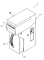
図1から図6は、本発明に係る紙葉書類装置の一実施形態である紙幣処理装置を示しており、図1は、全体構成を示す斜視図、図2は、開閉部材を装置本体の本体フレームに対して開いた状態を示す斜視図、図3は、装置本体の動力伝達部の構成を示す斜視図、図4は、挿入口から挿入される紙幣の搬送経路を概略的に示した右側面図、図5は、紙幣収容部に配設される押圧板を駆動するための動力伝達機構の概略構成を示す図、そして、図6は、紙幣搬送機構を駆動するための駆動源及び駆動力伝達機構の概略構成を示す左側面図である。 1 to 6 show a banknote processing apparatus which is an embodiment of a paper document apparatus according to the present invention. FIG. 1 is a perspective view showing the overall configuration, and FIG. FIG. 3 is a perspective view showing a configuration of a power transmission unit of the apparatus main body, and FIG. 4 schematically shows a conveyance path of a bill inserted from an insertion slot. FIG. 5 is a right side view, FIG. 5 is a diagram showing a schematic configuration of a power transmission mechanism for driving a pressing plate disposed in the banknote accommodating portion, and FIG. 6 is a driving source for driving the banknote transport mechanism and It is a left view which shows schematic structure of a driving force transmission mechanism.
本実施形態の紙幣処理装置1は、例えば、スロットマシン等の各種の遊技機に組み込み可能に構成されており、装置本体2と、この装置本体2に設けられ、多数の紙幣を積層、収容することが可能な紙幣収容部(紙幣収容スタッカ)100とを備えている。この紙幣収容部100は金庫としての機能を備えており、装置本体2を構成するフレーム2Aに対して着脱可能に構成されている。本実施形態では、例えば、図示されていないロック機構が解除された状態で、前面に設けられた取っ手101を引くことで、装置本体2のフレーム2Aから取り外すことが可能となっている。
The banknote handling
装置本体2は、図2及び図3に示すように、前記フレーム2Aと、フレーム2Aに対して一端部を回動中心として開閉されるように構成された開閉部材2Bとを有している。そして、これらフレーム2A及び開閉部材2Bは、図4に示すように、開閉部材2Bをフレーム2Aに対して閉じた際、両者の対向部分に紙幣が搬送される隙間(紙幣搬送路)3が形成されると共に、両者の前面露出側に、前記紙幣搬送路3に一致するようにして、紙幣挿入口5が形成されるよう構成されている。なお、前記紙幣挿入口5は、紙幣の短い辺側から装置本体2の内部に挿入できるようにスリット状の開口となっている。
As shown in FIGS. 2 and 3, the
前記装置本体2内には、紙幣を搬送する紙幣搬送機構6と、紙幣挿入口5に挿入された紙幣を検知する挿入検知センサ7と、挿入検知センサ7の下流側に設置され、搬送状態にある紙幣の情報を読取る紙幣読取手段8と、この紙幣読取手段8に対して、紙幣を正確に位置決めして搬送するスキュー補正機構10と、紙幣がスキュー補正機構10を構成する可動片を通過したことを検知する可動片通過検知センサ12と、紙幣が紙幣収容部100に排出されたことを検知する排出検知センサ18と、紙幣収容部100内で紙幣を載置プレート105に向けて押圧する押圧板115の位置を検出可能な検出手段23と、上記した紙幣搬送機構6、紙幣読取手段8、スキュー補正機構10及び検出手段23の駆動を制御する制御手段200(制御回路基板200A;図15参照)とが設けられている。
In the apparatus
以下、上記した各構成部材について、詳細に説明する。
前記紙幣搬送路3は、紙幣挿入口5から奥側に向けて延出しており、その後方側で下方に向けて傾斜するように屈曲され、そして最終的に鉛直方向に向けて屈曲するように形成されている。紙幣搬送路3には、紙幣収容部100に紙幣を排出する排出口3aが形成されており、ここから排出される紙幣は、鉛直方向に向けて、紙幣収容部100の導入口(受入口)103に送り込まれる。
Hereafter, each above-mentioned structural member is demonstrated in detail.
The
前記紙幣搬送機構6は、紙幣挿入口5から挿入された紙幣を挿入方向に沿って搬送可能にすると共に、挿入状態にある紙幣を紙幣挿入口5に向けて差し戻し搬送可能とする機構である。この紙幣搬送機構6は、装置本体2内に設置された駆動源であるモータ13(図6参照)と、このモータ13によって回転駆動され、紙幣搬送路3に紙幣搬送方向に沿って所定間隔おいて配設される搬送ローラ対(14A,14B)、(15A,15B)、(16A,16B)、及び(17A,17B)を備えている。
The banknote transport mechanism 6 is a mechanism that enables the banknote inserted from the
前記搬送ローラ対は、紙幣搬送路3に一部が露出するように設置されて、いずれも紙幣搬送路3の下側に設置される搬送ローラ14B,15B,16B及び17Bがモータ13によって駆動されるローラとなっており、上側に設置される搬送ローラ14A,15A,16A及び17Aが、これらのローラに対して従動するピンチローラとなっている。なお、紙幣挿入口5から挿入された紙幣を最初に挟持して奥側に搬送する搬送ローラ対(14A,14B)は、図2及び図3に示すように、紙幣搬送路3の中心位置に1箇所設置されており、その下流側に順次配置される搬送ローラ対(15A,15B)、(16A,16B)、及び(17A,17B)については、紙幣搬送路3の幅方向に沿って、所定間隔をおいて2箇所設置されている。
The pair of transport rollers is installed so that a part thereof is exposed in the
また、上記した紙幣挿入口5の近傍に配置される搬送ローラ対(14A,14B)については、通常は、上側の搬送ローラ14Aが下側の搬送ローラ14Bから離間した状態となっており、紙幣の挿入が挿入検知センサ7によって検知されると、上側の搬送ローラ14Aが下側の搬送ローラ14Bに向けて駆動され、挿入された紙幣を挟持するようになっている。なお、上側の搬送ローラ14Aについては、駆動源70(図15のブロック図参照)によって、搬送ローラ14Bに対して当接/離間するように駆動制御される。この駆動源70については、モータやソレノイド等によって構成することができ、開閉部材2B内に設置される。
Moreover, about the conveyance roller pair (14A, 14B) arrange | positioned in the vicinity of the above-mentioned
そして、前記スキュー補正機構10によって、挿入された紙幣の傾きを無くし紙幣読取手段8に対して位置合わせする処理(スキュー補正処理)が行われる際には、上側の搬送ローラ14Aは、下側の搬送ローラ14Bから離間して紙幣に対する負荷を解除し、スキュー補正処理が終了すると、再び、上側の搬送ローラ14Aが下側の搬送ローラ14Bに向けて駆動され、紙幣を挟持する。スキュー補正機構10は、スキューの補正を果たす左右一対の可動片10A(片側のみ図示)を備えており、スキュー駆動機構用のモータ40を駆動することでスキューの補正処理が成される。
When the
上記した紙幣搬送路3の下側に設置される搬送ローラ14B,15B,16B及び17Bは、図6に示すように、モータ13、及び各搬送ローラの駆動軸の端部に設置されるプーリ14C,15C,16C及び17Cを介して回転駆動される。すなわち、モータ13の出力軸には、駆動プーリ13Aが設置されており、上記した各搬送ローラの駆動軸の端部に設置されるプーリ14C,15C,16C及び17Cには、駆動プーリ13Aとの間で駆動ベルト13Bが巻回されている。なお、駆動ベルト13Bには、適所にテンションプーリが係合しており、弛みを防止している。
As shown in FIG. 6, the
上記した構成により、モータ13が正転駆動されると、前記搬送ローラ14B,15B,16B及び17Bは同期して正転駆動され、紙幣を挿入方向に向けて搬送し、モータ13が逆転駆動されると、前記搬送ローラ14B,15B,16B及び17Bは同期して逆転駆動され、紙幣を紙幣挿入口5側に向けて搬送する。
With the configuration described above, when the
前記挿入検知センサ7は、紙幣挿入口5に挿入された紙幣を検知した際に検知信号を発生するものであり、本実施形態では、搬送ローラ対(14A,14B)と、スキュー補正機構10との間に設置されている。前記挿入検知センサ7は、光学式のセンサ、例えば、回帰反射型フォトセンサによって構成されているが、それ以外にも、機械式のセンサによって構成されていても良い。
The
また、前記可動片通過検知センサ12は、紙幣の先端が、前記スキュー補正機構10を構成する左右一対の可動片10Aを通過したことを検知した際に検知信号を発生するものであり、前記紙幣読取手段8の上流側に設置されている。この可動片検知センサ12についても、前記挿入検知センサと同様、光学式のセンサや機械式のセンサによって構成される。
The movable piece
また、前記排出検知センサ18は、通過する紙幣の後端を検知して、紙幣が紙幣収容部100に排出されたことを検知するものであり、紙幣搬送路3の下流側において、紙幣収容部100の受入口103の直前に配設されている。この排出検知センサ18についても、前記挿入検知センサと同様、光学式のセンサや機械式のセンサによって構成される。
The
前記紙幣読取手段8は、スキュー補正機構10によってスキュー補正された状態(正確に位置決めされた状態)で搬送される紙幣について、その紙幣情報を読取り、その真贋を判定する。具体的には、例えば、搬送される紙幣の両面側から光を照射し、その透過光と反射光を受光素子で検知することで紙幣の読取を行うラインセンサによって構成することができる。図においては、ラインセンサが示されており、このラインセンサで読取った光信号は光電変換され、予め格納されている真券のデータと比較照合することで、搬送される紙幣の真贋を識別する。
The banknote reading means 8 reads the banknote information of a banknote conveyed in a state (correctly positioned) skew-corrected by the
次に、図4から図6に加え、図7から図14を参照して、紙幣収容部100の構成、及び紙幣を載置プレートに向けて押圧する押圧板の位置を検出可能な検出手段23の構成について説明する。
Next, referring to FIG. 7 to FIG. 14 in addition to FIG. 4 to FIG. 6, the detecting means 23 capable of detecting the configuration of the
なお、これらの図において、図7は、押圧板の駆動機構の一部を切欠いて示す斜視図、図8は、紙幣収容部の受入口部分を示す平面図であり、押圧板がホーム位置にある状態を示す図、図9は、紙幣収容部の受入口部分を示す平面図であり、押圧板が押圧位置(最大ストローク位置)にある状態を示す図、図10は、紙幣収容部の受入口部分を示す平面図であり、押圧板が待機位置にある状態を示す図、図11は、押圧板と検出手段の関係を示す図であり、(a)は押圧板が待機位置にある状態を示す図、(b)は押圧板が初期位置(ホーム位置)にある状態を示す図、(c)は押圧板が押圧位置にある状態を示す図、図12は、押圧板の位置を検出可能な検出手段の部分を示す斜視図、図13は、押圧板の位置を検出可能な検出手段の主要部を示す拡大図、そして、図14は、紙幣収容部を本体フレームから取り外した状態を示す側面図である。 In these drawings, FIG. 7 is a perspective view showing a part of the driving mechanism for the pressing plate, and FIG. 8 is a plan view showing the receiving portion of the banknote accommodating portion, with the pressing plate at the home position. FIG. 9 is a plan view showing a receiving portion of the banknote storage unit, FIG. 9 is a diagram showing a state where the pressing plate is in the pressing position (maximum stroke position), and FIG. It is a top view which shows an entrance part, and is a figure which shows the state which has a press plate in a standby position, FIG. 11 is a figure which shows the relationship between a press plate and a detection means, (a) is a state in which a press plate is in a standby position FIG. 12B is a diagram illustrating a state where the pressing plate is in the initial position (home position), FIG. 12C is a diagram illustrating a state where the pressing plate is in the pressing position, and FIG. 12 is a diagram illustrating detection of the position of the pressing plate. FIG. 13 is a perspective view showing a portion of a possible detection means, and FIG. Shown enlarged view, and FIG. 14 is a side view showing a state in which removal of the bill housing part from the body frame.
前記紙幣を収容する紙幣収容部100は、装置本体2のフレーム2Aに対して着脱可能に構成され(図14参照)、上記した紙幣読取手段8で真性と識別された紙幣を順次、積層、収容する。
The
図4から図6に示すように、紙幣収容部100を構成する本体フレーム100Aは、略直方体形状に構成されており、その前壁102aの内側には、付勢手段(付勢バネ)106の一端が取り付けられ、その他端には、上記した受入口103を介して送り込まれる紙幣を順次、積層する載置プレート105が設けられている。このため、載置プレート105は、前記付勢手段106を介して、後述する押圧板115側に向けて付勢された状態になっている。
As shown in FIGS. 4 to 6, the
本体フレーム100A内には、受入口103に連続するように、落下する紙幣をそのまま待機、保持させる押圧待機部108が設けられている。押圧待機部108の載置プレート側の両サイドには、鉛直方向に延出して一対の規制部材110が配置されている。この一対の規制部材110は、載置プレート105上に紙幣Mが順次、積層されて、前記付勢手段106によって載置プレート105が付勢された際、最上の紙幣M1の両サイドを当て付けて、積層される紙幣を安定して保持する役目を果たす(図10参照)。
In the
また、本体フレーム100A内には、受入口103から押圧待機部108に落下した紙幣を載置プレート105に向けて押圧する押圧板115が配設されている。この押圧板115は、前記一対の規制部材110の間に形成された開口部110Aを往復移動できる程度の大きさに構成されており、この開口部110A内に入り込んで、紙幣を載置プレート105に押し付ける位置(押圧位置;図9及び図11(c)参照)と、前記押圧待機部108を開放する位置(初期位置;図8及び図11(b)参照)との間で往復駆動される。
In addition, a
前記押圧板115は、本体フレーム100A内に配設される押圧板駆動機構120を介して、上記したように往復駆動される。押圧板駆動機構120は、押圧板115を、図5の矢印A方向に往復移動可能となるように、両端が押圧板115に軸支された一対のリンク部材115a,115bを備えており、これらのリンク部材115a,115bはX字状に連結され、それぞれの反対側の端部は、垂直方向(矢印B方向)に移動可能に設置された可動部材122に軸支されている。この可動部材122には、ラック122Aが形成されており、このラックには、押圧板駆動機構120を構成するピニオン124Aが噛合している。
The
このピニオン124Aには、図5に示すように、押圧板駆動機構120を構成する収容部側ギヤトレイン124が連結されている。この場合、本実施形態においては、図3及び図5に示すように、上述した装置本体2内に、駆動源(モータ20)と、このモータ20に順次噛合する本体側ギヤトレイン21が配設されており、紙幣収容部100を装置本体2に装着すると、本体側ギヤトレイン21が収容部側ギヤトレイン124に連結するようになっている。すなわち、収容部側ギヤトレイン124は、図12に示すように、ピニオン124Aと同軸上に配設されるギヤ124B、及びこれに順次噛合するギヤ124C,124Dを備えており、紙幣収容部100を装置本体2のフレーム2Aに対して着脱する際、ギヤ124Dが、本体側ギヤトレイン21の最終ギヤ21Aと噛合、離間するよう構成されている。
As shown in FIG. 5, the
この結果、上記した押圧板115は、装置本体2に設けられたモータ20が回転駆動されることで、本体側ギヤトレイン21、及び押圧板駆動機構120(収容部側ギヤトレイン124、可動部材122に形成されるラック122A、及びリンク部材115a,115b等)を介して、矢印A方向に往復駆動される。
As a result, the above-described
なお、本実施形態における上記した押圧板115は、モータ20によって矢印A方向に往復駆動される際、モータ20の停止制御によって3つの位置を取るようになっている。具体的には、図9及び図11(c)に示すように、紙幣を載置プレート105に押さえ付ける押圧位置(最大ストローク位置)と、図8及び図11(b)に示すように、押圧待機部108を開放する初期位置(ホーム位置)と、図10及び図11(a)に示すように、押圧板115を駆動する一対のリンク部材115a,115bが、押圧待機部108に位置しており、紙幣が一対のリンク部材115a,115bによって受入口103から押圧待機部108に搬入できない待機位置(規制部材110の開口部110Aが、押圧板115によって閉塞されている位置)の、3つの位置を取り得るようになっている。
Note that the
前記装置本体2のフレーム2A内には、図4に示すように、載置プレート105上に、所定枚数の紙幣が載置された際、その状態を検知する検知センサ(満杯検知センサ)140が設置されている。この満杯検知センサは、磁気信号を検知できるように構成されており、載置プレート105の裏面の中央に設けられた磁石140Aによる磁界を検知できるように構成されている。すなわち、満杯検知センサ140は、載置プレート105が押し込まれる方向の所定の位置に設置されており、載置プレート105上に紙幣が順次載置されて、載置プレート105が付勢手段106の付勢力に抗して押し込まれ、満杯検知センサ140が載置プレート105の移動を検知した際、載置プレート105上の紙幣が満杯になった信号を発する。
In the
また、本体フレーム100Aには、前記受入口103から搬入される紙幣に対して接触可能な搬送部材150が設置されている。この搬送部材150は、搬入される紙幣に接触して、安定して紙幣を押圧待機部108の適正位置(押圧板115で紙幣を押圧した際、紙幣が左右に片寄ることなく、安定して押圧できる位置)に案内する役目を果たす。本実施形態では、この搬送部材は、押圧待機部108に臨むように設置されたベルト状の部材(以下、ベルト150と称する)によって構成されている。
The
この場合、ベルト150は、紙幣に対して搬入方向に沿って延在するように設置されており、搬入方向の両端部に回転可能に支持された一対のプーリ150A,150Bに巻回されている。また、ベルト150は、受入口103の領域に回転可能に支持された軸方向に延出する搬送ローラ150Cと当接しており、受入口103に搬入された紙幣を挟持して、紙幣をそのまま押圧待機部108に案内するようにしている。さらに、本実施形態では、前記ベルト150は、紙幣の両サイドの表面に接触可能となるように、上記した押圧板115を挟むようにして左右一対設けられている。なお、ベルト150は、両端におけるプーリ150A,150Bの巻回以外に、中間位置でテンションプーリを当て付け、弛みを防止するようにしても良い。
In this case, the
前記一対のベルト150は、装置本体2内に設置される上述した複数の搬送ローラを駆動するモータ13によって駆動されるようになっている。具体的には、図6に示すように、モータ13によって駆動される上述した駆動ベルト13Bは、駆動力伝達用のプーリ13Dに巻回されており、このプーリ13Dに順次設置される動力伝達用のギヤトレイン13Eには、受入口103側に回転可能に支持されているプーリ150Aの支軸の端部に設置されたギヤトレイン153が噛合するようになっている。すなわち、紙幣収容部100が装置本体2に装着された際、ギヤトレイン13Eの最終ギヤ13Fには、ギヤトレイン153の入力ギヤ153Aが噛合するようになっており、一対のベルト150は、モータ13の回転駆動により、上述した紙幣搬送用の搬送ローラ14B,15B,16B,17Bと一体的に回転駆動されるようになっている。
The pair of
このように紙幣収容部に設置されるベルト150を駆動するに際しては、装置本体2に設けられている紙幣搬送機構6の駆動源であるモータ13を利用するため、コストを削減することが可能になる。
Thus, when driving the
また、本体フレーム100Aには、図8に示すように、受入口103から紙幣の搬入方向に沿って、紙幣の両側縁を規制するガイド部材160が形成されている。このガイド部材160は、搬入される紙幣の両縁を規制するコの字の案内面160aを有しており、紙幣が受入口103から紙幣収容部(押圧待機部108)内に搬入されると、ガイド部材160に沿って移動できると共に、紙幣と前記一対のベルト150が安定して摺接できるようになる。これにより、紙幣が押圧待機部108へ搬入される際の片寄りを修正して、紙幣をより確実に適正な位置に搬送できるようになる。
Further, as shown in FIG. 8, the
次に、上記した検出手段23の構成について説明する。検出手段23は、紙幣を載置プレート105に向けて押圧する押圧板115の位置を検出できるように構成されており、本実施形態では、押圧板115を駆動する上記したラック122A及びピニオン124Aに関連付けされて設けられている。また、この検出手段23は、紙幣収容部100を装置本体2のフレーム2Aに対して着脱した際、その着脱操作を検出できるように構成されている。
Next, the configuration of the detection means 23 will be described. The detection means 23 is configured to be able to detect the position of the
検出手段23は、押圧板115の移動に伴って移動可能な検出部材170と、押圧板115の押圧位置への移動によって検出部材170が移動したことを検出するセンサ172と、紙幣収容部100をフレーム2Aから取り外したとき、検出部材170をセンサ172で検出可能となるように移動させる移動機構180とを有している。
The detection means 23 includes a
前記検出部材170は、図11及び図12に示すように、上下方向に移動可能となるように装置本体2のフレーム2Aに支持されており、その一端側には検知部170aが形成され、他端側には係合部170bが形成されている。
As shown in FIGS. 11 and 12, the
前記センサ172は、光学式のセンサ素子によって構成されており、公知のように、発光部と受光部との間で、上記した検出部材170の検知部170aの移動を検知できるよう構成されている。検出部材170は、付勢部材171によって、常時、紙幣収容部側に向けて付勢されており、その付勢による検出部材170の移動は、他端側に形成される係合部170b、及び後述する移動機構180によって制限されている。
The
前記移動機構180は、上記したラック122Aに噛合するピニオン124Aと同軸上に並設されるカム部材175Aと、カム部材175Aに形成されるカム175と、このカム175と前記検出部材170の他端側に形成される係合部170bとの間に設置されるカムフォロワ(伝達部材)176と、を備えている。
The moving
ここで、ピニオン124A、カム175、カムフォロワ176、検出部材170に形成される係合部170b、及び検知部170aの移動を検知するセンサ172の関係について図11から図13を参照して説明する。
Here, the relationship among the pinion 124A, the
カム部材175Aに形成されるカム175は、カムフォロワ176を介して押圧板115が図11(c)に示す押圧位置と、図11(a)に示す待機位置との間を移動した際、前記検出部材170を移動させ、かつ、カムフォロワ176を介して押圧板115が図11(a)に示す待機位置と、図11(b)に示す初期位置との間を移動した際、前記検出部材170の移動を制限する形状を有している。
The
すなわち、押圧板115が図11(a)に示す待機位置から、図11(b)に示す初期位置へ移動したとき、前記検出部材170は、カム175の形状により移動することはなく、センサ172による検知がされることはない。また、押圧板115が図11(b)に示す初期位置から、図11(c)に示す押圧位置へ移動したとき、前記検出部材170は、付勢部材171の付勢力、並びにカム175及びカムフォロワ176によって下方に移動し、その状態(押圧位置への移動)がセンサ172によって検知される(検知部170aがセンサ172から離れたことが検知される)。そして、押圧板115が図11(c)に示す押圧位置から、図11(a)に示す待機位置へ移動したとき、前記検出部材170は、カム175及びカムフォロワ176によって上方に移動し、その状態(待機位置への移動)がセンサ172によって検知される(検知部170aがセンサ172によって検知される)。
That is, when the
また、カムフォロワ176は、支軸176aを支点として、本体フレーム100Aに回動可能に支持されており、回動方向の一端側には、カム175に当接するカム当接部176bが形成され、回動方向の他端側には、前記検出部材170に形成される係合部170bに当接する検出部材当接部176cが形成されている。
Further, the
この場合、図13(押圧位置を示している)に示すように、前記検出部材170には、紙幣収容部100をフレーム2Aに装着する際、カムフォロワ176の検出部材当接部176cと係合して検出部材170をセンサ172で検出可能な位置に移動させる案内面(傾斜面)170dが係合部170bと隣接して形成されている。
In this case, as shown in FIG. 13 (showing the pressing position), the
なお、カムフォロワ176には、押圧板115が押圧位置に移動した際、検出部材170の案内面170dによって回動が規制されるように、前記検出部材当接部176cと隣接して回動規制部176dが形成されている。すなわち、このような回動規制部176dを設けておくことで、図13に示すように、押圧板115が押圧位置に移動した際、回動可能に支持されたカムフォロワ176は、回動規制部176dが検出部材170の案内面170dによって回動が規制されるため、カムフォロワ176を安定した状態に維持することが可能となり、確実に検出部材170の移動をセンサ172によって検出することが可能となる。
The
また、図14に示すように、紙幣収容部100を装置本体2のフレーム2Aから取り外すと、上記した検出部材170は、カムフォロワ176との係合関係が解除され、図12に示す付勢部材171によって、紙幣収容部側に向けて移動される。この検出部材170の移動、すなわち、紙幣収容部100をフレーム2Aから取り外して検知部170aが移動したことは、センサ172によって検知される。
As shown in FIG. 14, when the
そして、上記したラック122Aが形成される可動部材122には、図12に示すように、可動部材122自身を、常時、装置本体側に向けて付勢する付勢バネ122Bが設置されている。すなわち、紙幣収容部100を装置本体2のフレーム2Aから取り外すと、ラック122Aは、付勢バネ122Bの付勢力によって、図11(b)に示す初期位置に移動するようになっている。この結果、紙幣収容部100を装置本体2のフレーム2Aに装着すると、図13に示すカムフォロワ176に形成された検出部材当接部176cが検出部材170の案内面170dに当接し、その案内面170dの形状により、検出部材170を付勢部材171の付勢力に抗して押し上げる。この検出部材170の押し上げ移動、すなわち、紙幣収容部100をフレーム2Aに装着して検知部170aが移動したことは、センサ172によって検知される。
The
次に、上述した紙幣搬送機構6、紙幣読取手段8、紙幣収容部100内に設置される押圧板115及び検出手段23の駆動を制御する制御手段について図15を参照して説明する。
Next, control means for controlling the driving of the above-described banknote transport mechanism 6, banknote reading means 8, pressing
制御手段200は、上記した各駆動装置の動作を制御する制御回路基板200Aを備えており、この制御回路基板上には、紙幣識別手段を構成するCPU(Central Processing Unit)210と、ROM(Read Only Memory)212と、RAM(Random
Access Memory)214と、基準データ記憶部216とが実装されている。
The control means 200 is provided with a
Access Memory) 214 and a reference
前記ROM212には、上述した紙幣搬送機構を駆動するモータ13、押圧板を駆動するモータ20、搬送ローラ14Aを搬送ローラ14Bに向けて当接/離間するように駆動する駆動源70、スキュー駆動機構10を駆動するためのモータ40等の各種駆動装置の作動プログラムや、紙幣読取手段8で読取る紙幣についての真贋判定プログラム等の各種プログラム、及び恒久的なデータが記憶されており、CPU210は、ROM212に記憶されている前記プログラムに従って制御信号を生成し、I/Oポート220を介して上述した各種駆動装置との間で信号の入出力を行い、各種駆動装置の駆動制御を行う。
The
また、CPU210には、I/Oポート220を介して、挿入検知センサ7、可動片通過検知センサ12、排出検知センサ18、満杯検知センサ140、及び押圧板115の位置を検出可能な検出手段23の一部を構成するセンサ172からの検知信号が入力されるようになっており、これらの検知信号に基づいて、各種駆動装置の駆動制御が行われる。
In addition, the
また、前記RAM214には、CPU210が作動する際に用いるデータやプログラムが記憶されており、基準データ記憶部216には、紙幣の真贋判定を行うときに用いられる基準データ、例えば、真券紙幣の全印刷領域から取得した各種のデータ(例えば、濃淡に関するデータ、赤外線を紙幣に投光した際の透過光や反射光に関するデータなど)が基準データとして記憶されている。なお、基準データについては、専用の基準データ記憶部216に記憶させているが、これをROM212に記憶させておいても良い。
The
そして、CPU210には、I/Oポート220を介して、上記した紙幣読取手段8を構成する紙幣読取用検知センサ(例えば、ラインセンサ)80が接続されており、この紙幣読取用検知センサ80で読取った紙幣読取データは、基準データ記憶部216に記憶されている基準データと比較され、紙幣の真贋判定処理が実行される。
The
なお、上述した紙幣処理装置の動作を制御する制御手段200は、一つの制御回路基板200A上に実装されているが、機能に応じて別の制御回路基板上に分散して配置されていても良い。
In addition, although the control means 200 which controls operation | movement of the banknote processing apparatus mentioned above is mounted on one
次に、上述した制御手段200によって実行される紙幣処理装置1における紙幣の処理動作について、図16から図22のフローチャートに従って説明する。
Next, the banknote processing operation in the
操作者が紙幣を紙幣挿入口5に挿入する際、紙幣挿入口の近傍に設置される搬送ローラ対(14A,14B)は、初期状態において離間した状態にある(後述するST16,ST56参照)。また、押圧板115は、図10及び図11(a)に示すように、押圧板115を駆動する一対のリンク部材115a,115bが押圧待機部108に位置しており、紙幣が一対のリンク部材115a,115bによって受入口103から押圧待機部108に搬入できない待機位置に設定されている(後述するST134参照)。すなわち、この状態では、一対の規制部材110の間に形成された開口部110Aに押圧板115が入り込んで開口部110Aは閉塞した状態となっており、紙幣収容部内に収容されている紙幣を抜き取ることができない状態となっている。
When the operator inserts a bill into the
さらに、搬送ローラ対(14A,14B)の下流側に位置するスキュー補正機構10を構成する一対の可動片10Aは、初期状態において、あらゆる紙幣の引き抜きができないように最小幅(例えば一対の可動片10Aの間隔が52mm;後述するST15,ST57参照)に移動した状態にある。
Further, the pair of
上記した搬送ローラ対(14A,14B)の初期状態では、皺のある紙幣であっても、操作者は容易に挿入することができる。そして、挿入検知センサ7によって紙幣の挿入が検知されると(ST01)、上述した押圧板115の駆動用のモータ20を所定量逆転駆動し(ST02)、押圧板115を初期位置に移動させる。この初期位置では、押圧待機部108は開放状態になっており(図8及び図11(b)参照)、紙幣は、紙幣収容部100内に搬入可能となっている。すなわち、モータ20を所定量逆転駆動することで、押圧板115は、本体側ギヤトレイン21、及び押圧板駆動機構120(収容部側ギヤトレイン124、可動部材122に形成されるラック122A、及びリンク部材115a,115b、)を介して待機位置から初期位置に駆動される。この押圧板115の移動により、図11(a)から(b)に示すように、押圧待機部108が開放され、紙幣が紙幣収容部内に搬入可能な状態となる。なお、このとき、上記したカム部材175Aに形成されるカム175は、図11(a)及び(b)に示すように、前記検出部材170の移動を制限する形状を有しているため、この押圧板115の移動については、センサ172によって検知されることはない。
In the initial state of the transport roller pair (14A, 14B) described above, the operator can easily insert even a banknote with a hook. When insertion of the banknote is detected by the insertion detection sensor 7 (ST01), the
また、上述した駆動源70を駆動し、上側の搬送ローラ14Aを下側の搬送ローラ14Bに当接するように移動させる。これにより、挿入された紙幣は搬送ローラ対(14A,14B)によって挟持される(ST03)。
Further, the drive source 70 described above is driven to move the
次いで、紙幣搬送路の開放処理が成される(ST04)。この開放処理は、図19に示すフローチャートに示すように、述したスキュー補正機構用のモータ40を逆転駆動することで、一対の可動片10Aを互いに離間する方向に駆動することで成される(ST100)。このとき、一対の可動片10Aの位置を検知する可動片検知センサによって、一対の可動片10Aが所定位置(最大幅位置)に移動したことが検知されると(ST101)、モータ40の逆転駆動が停止される(ST102)。この搬送路開放処理により、一対の可動片10A内に紙幣が進入できる状態になっている。なお、このST04の前段階では、紙幣搬送路3は、後述する搬送路閉鎖処理(ST15,ST57)によって閉鎖された状態にあるが、このように、紙幣挿入前に紙幣搬送路3を閉じておくことで、例えば、不正目的などで紙幣挿入口から板状の部材を挿入して、ラインセンサなどの素子を破損させることを防止することができる。
Subsequently, the banknote conveyance path opening process is performed (ST04). As shown in the flowchart of FIG. 19, this release process is performed by driving the pair of
次いで、紙幣搬送用のモータ13が正転駆動される(ST05)。紙幣は、搬送ローラ対(14A,14B)によって装置内部に搬送され、スキュー補正機構10よりも下流側に配設されている可動片通過検知センサ12が紙幣の先端を検知すると、紙幣搬送用のモータ13は停止される(ST06,ST07)。このとき、紙幣は、スキュー補正機構10を構成する一対の可動片10A間に位置している。
Next, the
引き続き、上述した駆動源70を駆動し、紙幣を挟持した状態となっている搬送ローラ対(14A,14B)を離間させる(ST08)。このとき、紙幣には、何等、負荷が作用していない状態となる。 Subsequently, the drive source 70 described above is driven, and the transport roller pair (14A, 14B) that is in a state of sandwiching the banknote is separated (ST08). At this time, the bill is not subjected to any load.
そして、この状態でスキュー補正作動処理を行う(ST09)。このスキュー補正作動処理は、上述したスキュー補正機構用のモータ40を正転駆動することで、一対の可動片10Aを互いに接近する方向に駆動することで成される。すなわち、このスキュー補正作動処理は、図20のフローチャートに示すように、上述したモータ40を正転駆動することで、一対の可動片10Aを、互いに接近する方向に移動する(ST110)。この可動片の移動は、制御手段における基準データ記憶部に登録されている紙幣の最小幅(例;幅62mm)となるまで実行され、これにより、紙幣は、両側に当て付く可動片10Aによって、スキューが補正され、正確な中心位置となるように位置決めされる。
Then, skew correction operation processing is performed in this state (ST09). This skew correction operation process is performed by driving the pair of
上述したようなスキュー補正作動処理が終了すると、引き続き、搬送路開放処理が実行される(ST10)。これは、上述したスキュー補正機構用のモータ40を逆転駆動することで、一対の可動片10Aを離間する方向に移動することで成される(図19のST100〜ST102参照)。
When the skew correction operation process as described above is completed, the conveyance path opening process is subsequently executed (ST10). This is achieved by moving the pair of
続いて、上述した駆動源70を駆動し、上側の搬送ローラ14Aを下側の搬送ローラ14Bに当接するように移動させ、紙幣を搬送ローラ対(14A,14B)に挟持させる(ST11)。その後、紙幣搬送用のモータ13を正転駆動して紙幣を装置内部に向けて搬送し、紙幣が紙幣読取手段8を通過する際に、紙幣の読取処理を実行する(ST12,ST13)。
Subsequently, the drive source 70 described above is driven, the
そして、搬送される紙幣が紙幣読取手段8を通過して、紙幣の後端が、可動片通過検知センサ12によって検知されると(ST14)、紙幣搬送路3の閉鎖処理が実行される(ST15)。この処理においては、まず、図21のフローチャートに示すように、紙幣の後端が、可動片通過検知センサ12によって検知された後、上述したモータ40を正転駆動することで、一対の可動片10Aを、互いに接近する方向に移動する(ST120)。次に、可動片検知センサによって、可動片10Aが所定位置(最小幅位置、例えば52mm)に移動したことが検知されると(ST121)、モータ40の正転駆動が停止される(ST122)。
And if the banknote conveyed passes the banknote reading means 8, and the trailing end of a banknote is detected by the movable piece passage detection sensor 12 (ST14), the closing process of the
この搬送路閉鎖処理により、一対の可動片10Aは、挿入可能なあらゆる紙幣の幅よりも狭い最小幅位置(幅52mm)に移動されており、これにより、紙幣の引き抜きを効果的に防止するようにしている。すなわち、このような紙幣搬送路の閉鎖処理を実行することで、挿入された紙幣の幅よりも、可動片10A間の距離が狭くなり、操作者が不正目的で紙幣を挿入口方向に向けて引き抜く行為を効果的に防止することが可能となる。
By this conveyance path closing process, the pair of
なお、この状態で上述した可動片検知センサが、可動片10Aの移動を検知した際、操作者が何らかの不正行為を行っているとみなし、所定の処理を実行するようにしても良い。例えば、紙幣処理装置の動作を管理する上位装置に対して不正操作信号(異常検知信号)を送信したり、紙幣処理装置に報知ランプを設けておき、これを点滅させたり、その後に操作者によって入力される入力受付(ST22)の処理を有効化することなく、強制的に排出動作を行う等の処理を実行しても良い。或いは、紙幣処理装置の動作を無効(例えば、処理の停止処理、紙幣の排出処理など)にする等、適正な処理を行うようにしても良い。
In this state, when the movable piece detection sensor described above detects the movement of the
また、上記した搬送路閉鎖処理(ST15)に引き続いて、上述した駆動源70を駆動し、紙幣を挟持可能な状態となっている搬送ローラ対(14A,14B)を離間させる搬送ローラ対離間処理が行われる(ST16)。この搬送ローラ対離間処理を行うことで、操作者が誤って紙幣を追加投入(二重投入)しても、紙幣は、搬送ローラ対(14A,14B)による送り動作を受けることはなく、また、ST15において接近した状態にある一対の可動片10Aの前端に突き当たることから、紙幣の二重投入動作を確実に防止することができる。
In addition, following the above-described conveyance path closing process (ST15), the conveyance roller pair separation process for driving the above-described drive source 70 to separate the conveyance roller pair (14A, 14B) in a state in which a bill can be clamped. Is performed (ST16). By carrying out this conveyance roller pair separation process, even if the operator mistakenly inserts (doublely inserts) banknotes, the banknotes are not subjected to the feeding operation by the pair of conveyance rollers (14A, 14B). In ST15, since it hits the front end of the pair of
上記した紙幣搬送路の閉鎖処理と共に、紙幣読取手段8が紙幣の後端までデータを読取ると、紙幣搬送用のモータ13を所定量駆動し、紙幣を所定位置(エスクロ位置;紙幣読取手段8の中心位置から13mm紙幣が下流側に搬送された位置)で停止させ、このときに、制御手段200において、紙幣の真贋判定処理を実行する(ST17〜ST20)。
When the banknote reading means 8 reads data up to the trailing edge of the banknote together with the above-described closing process of the banknote conveyance path, the
上記したST20の真贋判定処理において、紙幣が真券であると判定されると(ST21;Yes)、操作者の入力を受付ける(ST22)。これは、操作者が、サービスの提供(例えば、ゲーム装置であればゲーム開始に伴う受付処理)を受入れるべく、受入ボタンを押下する受入操作、及び、挿入した紙幣の返却処理を行うべく、返却ボタンを押下する処理が該当する。 In the authenticity determination process of ST20 described above, when it is determined that the banknote is a genuine note (ST21; Yes), the operator's input is accepted (ST22). This is because the operator receives a service (for example, a reception process associated with the start of the game in the case of a game device), a reception operation for pressing the reception button, and a return for the inserted banknote to be returned. This corresponds to the process of pressing a button.
そして、各種サービスの提供を受入れる操作が入力されると(ST23;Yes)、引き続き、この状態で紙幣搬送用のモータ13を正転駆動し、紙幣を、紙幣収容部100に向けて搬送する(ST24)。この紙幣の搬送に際しては、紙幣の後端が排出検知センサ18によって検知されるまでは紙幣搬送用のモータ13は正転駆動され(ST25)、紙幣の後端が排出検知センサ18によって検知されてから、紙幣搬送用のモータ13は所定量だけ正転駆動される(ST26,ST27)。
And if operation which accepts provision of various services is inputted (ST23; Yes), the
このST26、及びST27における紙幣搬送用のモータ13の正転駆動処理は、紙幣が、装置本体2の紙幣搬送路3の下流側にある排出口3aから紙幣収容部100の受入口103に搬入され、前記一対のベルト150が、搬入される紙幣の両側表面に接触して安定して、押圧待機部108に案内される駆動量に対応している。すなわち、紙幣の後端が排出検知センサ18によって検知された後、更に、所定量、紙幣搬送用のモータ13を正転駆動することで、前記一対のベルト150は、搬入される紙幣に接触しつつ紙幣送り方向に駆動され、紙幣を安定した状態で押圧待機部108に案内する。この場合、紙幣は、前記受入口103から紙幣搬入方向に沿って形成されているガイド部材160の案内面160aに沿って案内されることから、紙幣が押圧待機部108へ搬入される際、前記一対のベルト150の接触と相俟って、片寄りがなく適正な押圧位置に搬送されるようになり、押圧板115によって、左右対称に撓んで一対の規制部材110間の開口部110Aを通過して押圧処理が成される。
In the normal rotation driving process of the
そして、上記した紙幣搬送用のモータ13が停止した後、紙幣を載置プレート105上に載置すべく押圧板115の駆動処理を実行する(ST28)。
Then, after the
この押圧板115の駆動処理は、図22に示すフローチャートに従って実行される。
最初、押圧板115の駆動用のモータ20を所定量正転駆動することで、上記ST02において初期位置にある押圧板115を押圧位置まで移動させる(ST130)。このモータ20の正転回転駆動量は、モータ20がDCモータによって構成されていれば、例えばエンコーダを利用してパルスを発生させ、そのパルス数を計測することで所定の回転量を設定することが可能である。すなわち、このように駆動用のモータ20を所定量正転駆動することで、押圧板115は、本体側ギヤトレイン21、及び押圧板駆動機構120(収容部側ギヤトレイン124、可動部材122に形成されるラック122A、及びリンク部材115a,115b、)を介して初期位置から押圧位置に移動される。
The driving process of the
First, by driving the
この押圧板115の移動により、押圧待機部108にある紙幣は、図8から図9(図11(b)から(c))に示すように、一対の規制部材110間の開口部110Aを左右対称となるようにU字状に撓みながら通過し、最終的に載置プレート105上に押し付けられる。このとき、紙幣は、上述したように一対のベルト150によって、片寄りがなく適正な押圧位置に搬送されているので、押圧板115が移動しても、一対の規制部材110との間でジャム等が生じることなく、安定した状態で載置プレート105上に載置される。
Due to the movement of the
なお、上記したカム部材175Aは、図11(b)において時計回り方向に回転駆動されるため、そのカム175に係合していたカムフォロワ176のカム当接部176bの係合状態が解除され、上記した検出部材170は、付勢部材171の付勢力によって下側に押下げられる(カムフォロワ176は、支軸176aを支点として時計回り方向に回動される)。この検出部材170が下側へ移動することで、端部に形成されている検知部170aがセンサ172から外れるので、押圧板115が押圧位置に移動したことがセンサ172によって検知される(図11(c))。
The
押圧板115が押圧位置へ移動すると、紙幣が安定して載置プレート105に載置されるように、押圧板115はその押圧位置で所定時間(200ms)、待機処理され(ST131)、その後、押圧板115の駆動用のモータ20を逆転駆動する(ST132)。モータ20が逆転駆動されることで、上記したカム部材175Aは、図11(c)及び図13において反時計回り方向に回転駆動され、押圧板115が図11(a)に示す待機位置に移動したとき、カム175がカムフォロワ176のカム当接部176bに係合し、カムフォロワ176は、支軸176aを支点として反時計回り方向に回動される。このとき、検出部材170は、カムフォロワ176の検出部材当接部176cによって押し上げられ、端部に形成されている検知部170aがセンサ172によって検知される(図11(a))。すなわち、センサ172によって、押圧板115が押圧位置から待機位置に移動したことが検知されると、モータ20の駆動が停止され、押圧板115は待機位置に停止される(ST133;Yes,ST134)。上述したように、この待機位置では、紙幣の抜き取りができない状態となっている。
When the
なお、所定時間内にセンサ172が、押圧板115が押圧位置から待機位置に移動したことを検知しなければ、スタック動作に異常があったものとみなし、スタック動作に異常があった旨(エラー信号)を外部装置や報知手段等に送信する(ST133;No、ST133A)。
If the
そして、押圧板115が押圧位置から待機位置に移動した後、上述した満杯検知センサ140が載置プレート105の裏面に設けられた磁気を検知すれば(ST135;Yes)、紙幣収容部100が満杯に近づいていることを報知する(ST136;No、ST137)。これは、満杯検知センサ140が磁気を検知した後、所定回数以内(本実施形態では4回)を条件に繰り返すようにしており(ST138)、これにより、管理者は、紙幣収容部100に紙幣が満杯になる前に、紙幣収容部100を交換することが可能となる。
Then, after the
また、満杯検知センサ140が磁気を検知した後、更に、紙幣収容部100を交換することなく、5回以上の紙幣のスタック動作が繰り返されたことが検出されると(ST136;Yes)、これ以上、紙幣が挿入されないように、装置の無効化処理が実行される(ST136A)。この無効化処理は、利用者が紙幣を紙幣挿入口に挿入しても、内部に紙幣を搬送しないように、例えば、上述した紙幣搬送機構の駆動を停止する等の処理をすれば良い。
Further, after the
上述した処理手順のST21において、挿入された紙幣が真券でないと判別された場合、或いは、操作者によって返却ボタンが押下された場合(ST23;No)、搬送路開放処理を実行し(ST51、図19のST100〜ST102参照)、その後、紙幣搬送用のモータ13を逆転駆動し、搬送ローラ対(14A,14B)の挟持処理を実行した後、エスクロ位置に待機している紙幣を、紙幣挿入口5に向けて搬送する(ST52,53)。そして、挿入検知センサ7が紙幣挿入口5に向けて差し戻される紙幣の後端を検知した際に、紙幣搬送用のモータ13の逆転駆動を停止すると共に、上述した駆動源70を駆動し、紙幣を挟持した状態となっている搬送ローラ対(14A,14B)を離間させる(ST54〜ST56)。そして、搬送路閉鎖処理を実施し、一連の処理が終了する(ST57,図21のST120〜ST122参照)。
In ST21 of the above-described processing procedure, when it is determined that the inserted banknote is not a genuine note, or when the return button is pressed by the operator (ST23; No), the conveyance path opening process is executed (ST51, ST100 to ST102 in FIG. 19), then, the
また、図14に示すように、上述した紙幣収容部100をフレーム2Aから取り外すと(このとき押圧板115は待機位置にある)、上記した検出部材170は、カムフォロワ176との係合関係が解除されるため、付勢部材171によって、紙幣収容部側に向けて移動される。この検出部材170の移動、すなわち、紙幣収容部100をフレーム2Aから取り外したことは、センサ172によって検知される。
As shown in FIG. 14, when the above-described
そして、紙幣収容部100を取り外すことで、ラック122Aが形成された可動部材122は、図12に示す付勢バネ122Bによって、図11(b)に示す初期位置に移動される。この結果、紙幣収容部100を装置本体2のフレーム2Aに装着すると、図13に示すカムフォロワ176に形成された検出部材当接部176cが検出部材170の案内面170dに当接し、その案内面170dの形状により、検出部材170を付勢部材171の付勢力に抗して押し上げる。この検出部材170の押し上げ移動、すなわち、紙幣収容部100をフレーム2Aに装着したことは、センサ172によって検知される。なお、このとき、カムフォロワの検出部材当接部176cが検出部材170に形成された案内面170dに当接し、検出部材170をセンサ172で検出可能な位置に移動させるため、紙幣収容部100をフレーム2Aに対する装着をスムーズに行うことが可能となる。
And the
上記した構成の紙幣処理装置によれば、紙幣を押圧する押圧板115が初期位置から押圧位置に向けて移動された際、それに伴って検出部材170が移動し、この検出部材の移動をセンサ172で検知することで、押圧板115の位置を検出することが可能になる。また、検出部材170は、紙幣収容部100をフレーム2Aから取り外した際、上記した移動機構180によって、カム175との係合が解除されて移動されるため、この検出部材170の移動を同一のセンサ172で検知することが可能となる。この場合、センサ172による押圧板115の押圧位置の検知と、紙幣収容部100をフレーム2Aから取り外したときの検知は、共に検出部材170の移動に基づいてなされるが、前者は、紙幣収容時における押圧板115の一時的な収容駆動を検知するものであるため、時間を閾値に設定することで、両者の検知を同一のセンサ172で行うことが可能となり、これにより、構造を簡略化して、安価に紙幣収容部100の着脱の有無と、押圧板115の位置を検出できるようになる。
According to the banknote processing apparatus having the above-described configuration, when the
また、上述した構成では、図11(c),(a)に示すように、押圧板115が押圧位置から待機位置に移動したとき、検出部材170の移動がセンサ172によって検知されるようになっているため、従来技術のように、押圧板115を、センサが検知する初期位置に戻す必要がなくなる。すなわち、従来技術のように、押圧板115を押圧位置から待機位置へ戻すに際し、押圧位置からセンサにより検知可能な初期位置まで移動して、その後、待機位置に移動させる必要がなくなり、動作制御が簡略化される。
In the above-described configuration, as shown in FIGS. 11C and 11A, when the
また、紙幣の紙幣収容部100内への搬入を許容する場合は、押圧板115を待機位置から初期位置に所定量移動させれば良く、その際、検出部材170は、カムによって移動が制限されているため、センサ172による検出は成されず、センサの無用な制御が不要となる。
In order to allow the banknotes to be carried into the
以上、本発明の実施形態について説明したが、本発明は、上記した実施形態に限定されることなく、種々変形して実施することが可能である。本発明は、押圧板が押圧位置へ移動したことと、紙幣収容部が本体装置から取り外したことを、1つのセンサによって検知できるように構成されていれば良く、検出部材や移動機構の構成については適宜変形することが可能である。 As mentioned above, although embodiment of this invention was described, this invention is not limited to above-described embodiment, It is possible to implement various deformation | transformation. The present invention only needs to be configured so that it can be detected by one sensor that the pressing plate has moved to the pressing position and that the banknote storage unit has been removed from the main body device. Can be appropriately modified.
また、上述した各種の駆動部材を駆動する駆動源、或いは、その駆動源からの動力伝達機構については、一例を示したに過ぎず、適宜変形することが可能である。 Further, the drive source for driving the various drive members described above or the power transmission mechanism from the drive source is merely an example, and can be modified as appropriate.
本発明は、例えば、紙幣が挿入されたことで、商品やサービスを提供する各種の装置に組み込むことが可能である。また、紙幣に限られず、クーポン券のような紙葉類を処理する処理装置に適用することが可能である。 For example, the present invention can be incorporated into various devices that provide goods and services by inserting bills. Moreover, it is not restricted to a banknote, It is possible to apply to the processing apparatus which processes paper sheets like a coupon.
1 紙幣処理装置
2 装置本体
2A フレーム
3 紙幣搬送路
5 紙幣挿入口
6 紙幣搬送機構
8 紙幣読取手段
10 スキュー補正機構
23 検出手段
40 駆動源
100 紙幣収容部
103 受入口
105 載置プレート
108 押圧待機部
115 押圧板
120 押圧板駆動機構
122 可動部材
122A ラック
124A ピニオン
170 検出部材
172 センサ
175A カム部材
175 カム
176 カムフォロワ
180 移動機構
200 制御手段
DESCRIPTION OF
Claims (3)
前記紙葉類収容部内において、紙葉類を押圧する押圧位置と、紙葉類の紙葉類収容部内への搬入を許容するホーム位置との間で移動される押圧板と、
前記押圧板の移動に伴って移動可能な検出部材と、
前記押圧板の押圧位置への移動によって前記検出部材が移動したことを検出するセンサと、
前記紙葉類収容部を前記フレームから取り外したとき、前記検出部材を前記センサで検出可能となるように移動させる移動機構と、
を有し、
前記押圧板は、前記押圧位置とホーム位置との間で紙葉類の紙葉類収容部内への搬入を阻止する待機位置へ移動可能であり、
前記移動機構は、前記検出部材の移動を制限するカムを備え、
前記カムは、前記押圧板が押圧位置と待機位置との間を移動した際、前記検出部材を移動させ、前記押圧板が待機位置とホーム位置との間を移動した際、前記検出部材の移動を制限する形状を有することを特徴とする紙葉類処理装置。 A paper sheet storage section that is detachable from the frame and that can store paper sheets;
In the paper sheet storage unit, a pressing plate that is moved between a pressing position that presses the paper sheet and a home position that allows the paper sheet to be carried into the paper sheet storage unit,
A detection member movable along with the movement of the pressing plate;
A sensor for detecting that the detection member has moved by movement of the pressing plate to the pressing position;
A moving mechanism that moves the detection member so that the sensor can be detected when the paper sheet container is removed from the frame;
I have a,
The pressing plate is movable between a pressing position and a home position to a standby position for preventing paper sheets from being carried into the paper sheet storage unit,
The moving mechanism includes a cam that restricts movement of the detection member;
The cam moves the detection member when the pressing plate moves between the pressing position and the standby position, and moves the detection member when the pressing plate moves between the standby position and the home position. A paper sheet processing apparatus, characterized by having a shape that restricts .
前記検出部材は、前記紙葉類収容部を前記フレームに装着する際、前記伝達部材の当接部と係合して検出部材を前記センサで検出可能な位置に移動させる案内面を有することを特徴とする請求項1に記載の紙葉類処理装置。 The moving mechanism has a transmission member that is installed between the detection member and the cam and includes a contact portion that contacts the detection member;
The detection member includes a guide surface that engages with a contact portion of the transmission member and moves the detection member to a position that can be detected by the sensor when the paper sheet accommodating portion is mounted on the frame. The paper sheet processing apparatus according to claim 1 , wherein
前記伝達部材は回動可能に支持され、前記押圧板が押圧位置に移動した際、前記検出部材の案内面によって回動を規制する回動規制部を有することを特徴とする請求項2に記載の紙葉類処理装置。 The detection member is urged to abut against the contact portion of the transmission member,
The transmission member is rotatably supported, when the pressing plate is moved to the pressing position, according to claim 2, characterized in that it comprises a rotation regulating portion for regulating the rotation by the guide surface of the detecting member Paper sheet processing equipment.
Priority Applications (3)
| Application Number | Priority Date | Filing Date | Title |
|---|---|---|---|
| JP2007304185A JP5184062B2 (en) | 2007-11-26 | 2007-11-26 | Paper sheet processing equipment |
| US12/744,787 US8215634B2 (en) | 2007-11-26 | 2008-11-07 | Paper sheet processing device |
| PCT/JP2008/070349 WO2009069452A1 (en) | 2007-11-26 | 2008-11-07 | Paper sheet processing device |
Applications Claiming Priority (1)
| Application Number | Priority Date | Filing Date | Title |
|---|---|---|---|
| JP2007304185A JP5184062B2 (en) | 2007-11-26 | 2007-11-26 | Paper sheet processing equipment |
Publications (2)
| Publication Number | Publication Date |
|---|---|
| JP2009129235A JP2009129235A (en) | 2009-06-11 |
| JP5184062B2 true JP5184062B2 (en) | 2013-04-17 |
Family
ID=40678354
Family Applications (1)
| Application Number | Title | Priority Date | Filing Date |
|---|---|---|---|
| JP2007304185A Active JP5184062B2 (en) | 2007-11-26 | 2007-11-26 | Paper sheet processing equipment |
Country Status (3)
| Country | Link |
|---|---|
| US (1) | US8215634B2 (en) |
| JP (1) | JP5184062B2 (en) |
| WO (1) | WO2009069452A1 (en) |
Families Citing this family (5)
| Publication number | Priority date | Publication date | Assignee | Title |
|---|---|---|---|---|
| CN102760325B (en) * | 2011-04-29 | 2014-11-05 | 山东新北洋信息技术股份有限公司 | Paper currency processing unit and paper currency delivery state detecting method |
| CN103848256A (en) * | 2012-11-30 | 2014-06-11 | 山东新北洋信息技术股份有限公司 | Bill pressing mechanism and storage box with same |
| CN106742212B (en) * | 2017-01-20 | 2022-08-02 | 浙江维融电子科技股份有限公司 | Paper money bundling mechanism |
| JP7463751B2 (en) * | 2020-02-10 | 2024-04-09 | ヤマハ株式会社 | Microphone device |
| US11667489B2 (en) * | 2020-11-25 | 2023-06-06 | Ncr Corporation | Short travel pusher plate stacking bin |
Family Cites Families (7)
| Publication number | Priority date | Publication date | Assignee | Title |
|---|---|---|---|---|
| JPS52107698U (en) * | 1976-02-13 | 1977-08-16 | ||
| JP3169387B2 (en) * | 1991-04-04 | 2001-05-21 | 東洋通信機株式会社 | Paper sheets storage monitoring device |
| JP2558985Y2 (en) * | 1991-06-21 | 1998-01-14 | 日本金銭機械株式会社 | Bill handling equipment |
| JPH0549755U (en) * | 1991-12-11 | 1993-06-29 | 沖電気工業株式会社 | Storage set detection mechanism |
| JPH0731746B2 (en) * | 1992-12-21 | 1995-04-10 | 株式会社日本コンラックス | Banknote machine |
| US5411249A (en) | 1994-01-10 | 1995-05-02 | Mars Incorporated | Currency validator and cassette transport alignment apparatus |
| JP3765850B2 (en) * | 1995-06-30 | 2006-04-12 | 日本金銭機械株式会社 | Banknote handling equipment |
-
2007
- 2007-11-26 JP JP2007304185A patent/JP5184062B2/en active Active
-
2008
- 2008-11-07 US US12/744,787 patent/US8215634B2/en active Active
- 2008-11-07 WO PCT/JP2008/070349 patent/WO2009069452A1/en active Application Filing
Also Published As
| Publication number | Publication date |
|---|---|
| US20100301542A1 (en) | 2010-12-02 |
| WO2009069452A1 (en) | 2009-06-04 |
| JP2009129235A (en) | 2009-06-11 |
| US8215634B2 (en) | 2012-07-10 |
Similar Documents
| Publication | Publication Date | Title |
|---|---|---|
| JP5188167B2 (en) | Paper sheet processing equipment | |
| JP5184104B2 (en) | Paper sheet processing equipment | |
| JP5124254B2 (en) | Banknote handling equipment | |
| JP5191035B2 (en) | Paper sheet processing equipment | |
| JP5317263B2 (en) | Paper sheet processing equipment | |
| JP5210067B2 (en) | Paper sheet processing equipment | |
| JP5210012B2 (en) | Paper sheet processing equipment | |
| JP5388265B2 (en) | Paper sheet processing equipment | |
| JP5184062B2 (en) | Paper sheet processing equipment | |
| JP5210013B2 (en) | Paper sheet processing equipment | |
| JP5024949B2 (en) | Paper sheet processing equipment | |
| JP5091619B2 (en) | Banknote handling equipment | |
| JP5546071B2 (en) | Paper sheet processing apparatus and paper sheet processing system | |
| JP5164255B2 (en) | Paper processing equipment | |
| JP5188199B2 (en) | Paper sheet processing equipment | |
| JP5209977B2 (en) | Paper sheet processing equipment | |
| JP5091593B2 (en) | Banknote handling equipment | |
| JP5269424B2 (en) | Paper sheet processing equipment |
Legal Events
| Date | Code | Title | Description |
|---|---|---|---|
| A621 | Written request for application examination |
Free format text: JAPANESE INTERMEDIATE CODE: A621 Effective date: 20101018 |
|
| A131 | Notification of reasons for refusal |
Free format text: JAPANESE INTERMEDIATE CODE: A131 Effective date: 20121004 |
|
| A521 | Request for written amendment filed |
Free format text: JAPANESE INTERMEDIATE CODE: A523 Effective date: 20121127 |
|
| TRDD | Decision of grant or rejection written | ||
| A01 | Written decision to grant a patent or to grant a registration (utility model) |
Free format text: JAPANESE INTERMEDIATE CODE: A01 Effective date: 20130110 |
|
| A61 | First payment of annual fees (during grant procedure) |
Free format text: JAPANESE INTERMEDIATE CODE: A61 Effective date: 20130116 |
|
| R150 | Certificate of patent or registration of utility model |
Ref document number: 5184062 Country of ref document: JP Free format text: JAPANESE INTERMEDIATE CODE: R150 Free format text: JAPANESE INTERMEDIATE CODE: R150 |
|
| FPAY | Renewal fee payment (event date is renewal date of database) |
Free format text: PAYMENT UNTIL: 20160125 Year of fee payment: 3 |
|
| R250 | Receipt of annual fees |
Free format text: JAPANESE INTERMEDIATE CODE: R250 |
|
| R250 | Receipt of annual fees |
Free format text: JAPANESE INTERMEDIATE CODE: R250 |
|
| R250 | Receipt of annual fees |
Free format text: JAPANESE INTERMEDIATE CODE: R250 |
|
| R250 | Receipt of annual fees |
Free format text: JAPANESE INTERMEDIATE CODE: R250 |
|
| R250 | Receipt of annual fees |
Free format text: JAPANESE INTERMEDIATE CODE: R250 |
|
| R250 | Receipt of annual fees |
Free format text: JAPANESE INTERMEDIATE CODE: R250 |
|
| R250 | Receipt of annual fees |
Free format text: JAPANESE INTERMEDIATE CODE: R250 |
|
| R250 | Receipt of annual fees |
Free format text: JAPANESE INTERMEDIATE CODE: R250 |
|
| R250 | Receipt of annual fees |
Free format text: JAPANESE INTERMEDIATE CODE: R250 |