JP5183345B2 - Structure to prevent the spread of greening structures - Google Patents
Structure to prevent the spread of greening structures Download PDFInfo
- Publication number
- JP5183345B2 JP5183345B2 JP2008196586A JP2008196586A JP5183345B2 JP 5183345 B2 JP5183345 B2 JP 5183345B2 JP 2008196586 A JP2008196586 A JP 2008196586A JP 2008196586 A JP2008196586 A JP 2008196586A JP 5183345 B2 JP5183345 B2 JP 5183345B2
- Authority
- JP
- Japan
- Prior art keywords
- partition wall
- roof
- plant layer
- spread
- fire
- Prior art date
- Legal status (The legal status is an assumption and is not a legal conclusion. Google has not performed a legal analysis and makes no representation as to the accuracy of the status listed.)
- Active
Links
Images


Classifications
-
- Y—GENERAL TAGGING OF NEW TECHNOLOGICAL DEVELOPMENTS; GENERAL TAGGING OF CROSS-SECTIONAL TECHNOLOGIES SPANNING OVER SEVERAL SECTIONS OF THE IPC; TECHNICAL SUBJECTS COVERED BY FORMER USPC CROSS-REFERENCE ART COLLECTIONS [XRACs] AND DIGESTS
- Y02—TECHNOLOGIES OR APPLICATIONS FOR MITIGATION OR ADAPTATION AGAINST CLIMATE CHANGE
- Y02A—TECHNOLOGIES FOR ADAPTATION TO CLIMATE CHANGE
- Y02A30/00—Adapting or protecting infrastructure or their operation
- Y02A30/24—Structural elements or technologies for improving thermal insulation
- Y02A30/254—Roof garden systems; Roof coverings with high solar reflectance
-
- Y—GENERAL TAGGING OF NEW TECHNOLOGICAL DEVELOPMENTS; GENERAL TAGGING OF CROSS-SECTIONAL TECHNOLOGIES SPANNING OVER SEVERAL SECTIONS OF THE IPC; TECHNICAL SUBJECTS COVERED BY FORMER USPC CROSS-REFERENCE ART COLLECTIONS [XRACs] AND DIGESTS
- Y02—TECHNOLOGIES OR APPLICATIONS FOR MITIGATION OR ADAPTATION AGAINST CLIMATE CHANGE
- Y02B—CLIMATE CHANGE MITIGATION TECHNOLOGIES RELATED TO BUILDINGS, e.g. HOUSING, HOUSE APPLIANCES OR RELATED END-USER APPLICATIONS
- Y02B80/00—Architectural or constructional elements improving the thermal performance of buildings
- Y02B80/32—Roof garden systems
Landscapes
- Cultivation Of Plants (AREA)
Description
本発明は、建物の屋根や屋上に設置された緑化構造体の延焼を防止する延焼防止構造に関する。 The present invention relates to a fire spread prevention structure for preventing the spread of a greening structure installed on the roof or roof of a building.
近年、ヒートアイランド現象の緩和や二酸化炭素排出量の削減による地球温暖化防止の観点から、建物の屋根や屋上を植物で覆う緑化が盛んに行われている。屋根や屋上の緑化では、屋根や屋上の上に不燃性の土壌層を有する人工地盤が形成され、この人工地盤の土壌層の上に例えば芝草等の植物が植栽されて、平面状に広がる植物層が形成される。植物は可燃性物質であり、特に、冬季のように植物の葉茎が枯れている場合には、燃えやすい状態となっている。従って、例えば、たばこの火や花火の不始末、近隣火災による火の粉の飛来等、何らかの理由によって着火した場合に植物層が延焼するおそれがある。なお、特許文献1には、屋上緑化等の人工土壌を複数の区画に区切り、人工土壌の延焼を防止する技術が示されている。
In recent years, from the viewpoint of mitigating the heat island phenomenon and preventing global warming by reducing carbon dioxide emissions, greening has been actively carried out to cover the roof and rooftop of buildings with plants. In the greening of roofs and rooftops, artificial ground having an incombustible soil layer is formed on the roof or rooftop, and plants such as turf grass are planted on the soil layer of this artificial ground and spread in a flat shape. A plant layer is formed. Plants are flammable substances, and are particularly flammable when the leaf stems of the plants are withered, such as in winter. Therefore, for example, if the fire is ignited for some reason, such as a cigarette fire or fireworks misfire, or a spark from a nearby fire, the plant layer may spread.
植物層の延焼は、その表面に沿って這うように進み、例えば横風によって火の粉が飛び、隣接領域に新たな火種が形成され、延焼が加速度的に進行するおそれがある。従って、延焼を防ぐ手段を設けなければ、緑化構造体の植物層が全面に亘って延焼するおそれがある。 The spread of the plant layer proceeds so as to crawl along the surface. For example, there is a possibility that sparks fly by a cross wind, a new fire type is formed in an adjacent region, and the spread of the fire proceeds at an accelerated rate. Therefore, if a means for preventing the spread of fire is not provided, the plant layer of the greening structure may spread over the entire surface.
本発明の発明者は、鋭意研究の結果、緑化構造体の植物層に火がついた場合に、植物層の表面のみ温度が上昇し、人工土壌の内部は温度上昇しないことを実験により見出した。特許文献1の技術は、人工土壌の火災を想定してなされたものであり、人工土壌から上方に伸びる植物は想定していない。従って、特許文献1の技術を用いたとしても、植物層特有の延焼方法を止めることは困難である。
As a result of earnest research, the inventor of the present invention has found through experiments that when the plant layer of the greening structure is lit, the temperature rises only on the surface of the plant layer and the temperature inside the artificial soil does not rise. . The technique of
本発明は、上記の点に鑑みてなされたものであり、その目的とするところは、建物の屋根や屋上に設置された緑化構造体の植物層が延焼するのを防ぐ延焼防止構造を提供することである。 This invention is made | formed in view of said point, The place made into the objective provides the fire spread prevention structure which prevents the plant layer of the greening structure installed in the roof of a building, or a rooftop from spreading. That is.
本発明の緑化構造体の延焼防止構造は、屋根又は屋上に敷設される緑化構造体の延焼防止構造において、緑化構造体の植物層を複数の領域に区画する耐火性或いは難燃性の仕切壁部を有し、仕切壁部は、上下に延在して植物層の下端から植物層よりも上方の高さ位置まで突出する縦壁部と、縦壁部の上端から互いに離反する方向に突出する一対の上端片部とを有することを特徴としている。 The fire spread prevention structure of the greening structure of the present invention is a fireproof or flame retardant partition wall that partitions the plant layer of the greening structure into a plurality of regions in the fire spread prevention structure of the greening structure laid on the roof or rooftop. The partition wall portion extends vertically and protrudes from the lower end of the plant layer to a height position above the plant layer, and protrudes in a direction away from the upper end of the vertical wall portion. And a pair of upper end pieces.
本発明に係わる緑化構造体の延焼防止構造によれば、仕切壁部で仕切られた領域内の植物層に火がついた場合に、上端縁部によって火炎や火の粉を植物層が燃えている領域内に戻るように折り返させることができ、仕切壁部で隔てられた隣接する他の領域に、火炎や火の粉が進入するのを防ぐことができ、延焼範囲をその領域内に留めて、隣接する領域内に火が移るのを防ぎ、延焼の拡大を確実に防ぐことができる。 According to the spread fire prevention structure of the greening structure according to the present invention, when the plant layer in the region partitioned by the partition wall is lit, the region where the plant layer is burning flame or sparks by the upper edge. It can be folded back to the inside, can prevent the intrusion of flames and sparks into other adjacent areas separated by the partition wall, and the fire spread area stays in that area and is adjacent It is possible to prevent the fire from moving into the area and reliably prevent the spread of fire spread.
本発明の緑化構造体の延焼防止構造が有する好ましい態様の一つとして、仕切壁部は、一対の上端片部が植物層の上方に所定距離だけ離間した高さ位置で植物層と平行に延在して植物層の上面に対向していることを特徴としている。 As one of the preferable embodiments of the greening structure of the greening structure according to the present invention, the partition wall portion extends in parallel with the plant layer at a height position where the pair of upper end pieces are separated by a predetermined distance above the plant layer. It is characterized by existing and facing the upper surface of the plant layer.
また、本発明の緑化構造体の延焼防止構造が有する好ましい態様の一つとして、仕切壁部は、断面がコ字型を有する一対の長尺部材を、その長尺部材の開放部分が側方に向かって開口するように互いに背中合わせの状態に組み合わせて形成した構成としてもよい。 Further, one preferred embodiment of fire prevention structure greening structure of the present invention has the partition wall, a pair of elongate members which cross section has a U-shaped, the open portion of the elongated member side It is good also as a structure formed combining in a back-to-back state so that it may open toward the direction .
また、本発明の緑化構造体の延焼防止構造が有する好ましい態様の一つとして、仕切壁部は、植物層を前記屋根又は屋上の勾配方向に区画する緯仕切壁部材と、植物層を屋根又は屋上の勾配方向に交差する横幅方向に区画する経仕切壁部とを有することを特徴としている。そしてさらに、本発明の緑化構造体の延焼防止構造が有する好ましい態様の一つとして、仕切壁部は、上端片部の突出幅が、上端片部の上を歩行可能な大きさに設定されていることを特徴としている。かかる構成とすることにより、作業者等は、上端片部の上を歩行することができる。従って、例えば植物層の植物を傷つけずに植物の管理を行うことができ、管理作業の簡単化を図ることができる。 Moreover, as one of the preferable aspects which the fire spread prevention structure of the greening structure of the present invention has, the partition wall section includes a weft partition wall member that divides the plant layer in the roof or roof slope direction, and the plant layer as a roof or It is characterized by having a partition wall section that is partitioned in the lateral width direction that intersects the slope direction of the roof. And as one of the preferable aspects which the fire spread prevention structure of the greening structure of this invention has, as for the partition wall part, the protrusion width | variety of an upper end piece part is set to the magnitude | size which can walk on an upper end piece part. It is characterized by being. By setting it as this structure, an operator etc. can walk on an upper end piece part. Therefore, for example, plants can be managed without damaging plants in the plant layer, and management work can be simplified.
本発明によれば、植物層を仕切壁部で複数の領域に区画するので、ある領域内の植物層に火がついて燃えたときに、延焼範囲をその領域内に留めることができ、他の領域の植物層に火が移るのを防ぐことができる。従って、延焼の拡大を確実に防ぐことができる。 According to the present invention, since the plant layer is partitioned into a plurality of regions by the partition wall portion, when the plant layer in a certain region is lit and burned, the fire spread range can be kept in that region, It can prevent the fire from transferring to the plant layer in the area. Therefore, it is possible to reliably prevent the spread of fire spread.
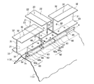
以下、図面を参照しながら、本発明を実施の形態に基づき説明する。本実施の形態では、立ちはぜ折板屋根Rの上に敷設される屋根緑化構造体A1の延焼防止構造について説明する。図1は立ちはぜ折板屋根Rの一例を示すものであり、図1(a)は、立ちはぜ折板屋根Rの構成を一部破断により示す斜視図、図1(b)は、立ちはぜ折板屋根Rを構成する屋根板3の断面図である。そして、図2は立ちはぜ折板屋根Rの上に仕切壁部材20、30を取り付けた状態を示す図、図3は立ちはぜ折板屋根Rに対する仕切壁部材20、30の取付構造を示す要部拡大図である。そして、図4は仕切壁部材を取り付けるためのクランプ60の基本形態を示し、図5は立ちはぜ折板屋根Rとその上に固定された屋根緑化構造体A1を示す平面図、図6は図5のI−I線断面矢視図、図7は図5のII−II線断面矢視図である。
Hereinafter, the present invention will be described based on embodiments with reference to the drawings. In the present embodiment, a fire spread prevention structure of the roof greening structure A1 laid on the standing folded plate roof R will be described. FIG. 1 shows an example of a standing folded-plate roof R. FIG. 1 (a) is a perspective view showing the configuration of the standing folded-plate roof R in a partially broken state, and FIG. It is sectional drawing of the
立ちはぜ折板屋根Rは、左右の立ち上がり縁の上端部に互いに係合する湾曲部3a,3bを形成した長尺状の屋根板3を(図1(b)を参照)、隣接する屋根板3,3の湾曲部同士を係合(はぜ継ぎ)しながら、梁5の上に専用の取り付け具6を利用して固定するようにしており、屋根勾配方向であるX方向に走る山形部1が屋根横幅方向であるY方向に所定ピッチPaで連続している。そして、該山形部1の頂部2には屋根板3を連接したときの丸みを持つ立ちはぜ突条4が屋根勾配方向に走っている。このような立ちはぜ折板屋根Rの上に緑化基盤である保水排水基盤材10、及び仕切壁部材20、30を固定して、保水排水基盤材10の上に芝草等の植物を植栽することによって屋根緑化構造体A1とされる。
The standing folded plate roof R is a long roof plate 3 (see FIG. 1 (b)) in which curved
図4は、立ちはぜ折板屋根Rの上に保水排水基盤材10及び仕切壁部材20、30を固定するクランプ60の基本形態を示す。クランプ60は、一定の横幅を持つ左右一対のクランプ片61,61で構成される。各クランプ片61は、立ちはぜ突条4の下方領域を押さえ付ける挟持先端部62aとその上方の第1の水平部62bとからなる膨出部63と、前記挟持先端部62aの先端位置とほぼ同じ垂直位置において前記第1の水平部62bから立ち上がる垂直部64と、該垂直部64の上端に位置する第2の水平部65とを有し、垂直部64には左右のクランプ片61、61を一体に締め付けるときに用いるボルトのためのボルト孔66が形成されている。また、水平部65にはボルト孔67が形成されている。なお、ボルトナットでなくドリルビス等を用いて左右のクランプ片61、61を一体に締め付けるようにしてもよく、その場合には、ボルト孔67を省略することができる。また、左右のクランプ片61、61のボルト孔66の一方を、ボルト孔に替えてより径の小さい小孔としてもよい。
FIG. 4 shows a basic form of a
前記膨出部63の内面側の形状は、好ましくは立ちはぜ突条4の外郭形状に一致した形状であり、その大きさは、左右のクランプ片61、61を締め付けたときに立ちはぜ突条4をわずかに圧縮して変形させるように大きさとされる。しかし、膨出部63の内面側の形状は、左右のクランプ片61、61を締め付けたときに、その内周面が部分的に突条4に接触するような形状、あるいはまったく接しない形状であっても差し支えない。挟持先端部62a,62aの先端は、図4又は図6に示すように、先端が外側に離反し、突条4に当たる面が曲面とされている。図示しないが、立ちはぜ突条4と該突条4を挟持するクランプ片61,61との間にパッキン材を介装してもよい。この構成とすることにより、立ちはぜ突条4とクランプ60とが直接接触しないようになり、立ちはぜ突条4の防錆処理が剥がれた場合でも、防食電流の流れを効果的に防止することができ、立ちはぜ突条4の腐食による劣化を長期にわたって回避することができる。
The shape on the inner surface side of the bulging
クランプ60の立ちはぜ突条4への固定に際しては、図4に示すように、左右のクランプ片61,61の膨出部63の間に立ちはぜ突条4を挟み込んだ姿勢とし、双方の垂直部64に形成したボルト孔66にボルトを通してナットで締め付ける。一定の横幅を持つ挟持先端部62の先端と膨出部63の内面側とで突条4を両側から押さえ付けた状態で、クランプ60は突条4に固定されるので、クランプ60の固定状態はきわめて安定したものとなる。
When the
図2に示すように、上記のクランプ60を用いて仕切壁部材20、30を立ちはぜ折板屋根Rに固定する。仕切壁部材20、30は、立ちはぜ折板屋根Rの上に、その屋根勾配方向及び屋根横幅方向に沿って固定され、立ちはぜ折板屋根Rの上部を複数の領域に区画する。
As shown in FIG. 2, the
最初に、屋根横幅方向に沿って固定される緯仕切壁部材20の固定態様を説明する。図2及び図3に示すように、立ちはぜ折板屋根Rにおける緯仕切壁部材20を固定すべき位置における立ちはぜ突条4に、一対のクランプ片61,61で立ちはぜ突条4を左右から挟み付けるようにして適数のクランプ60を固定する。そして、緯仕切壁部材20をクランプ60の第2の水平部65の上に載せて、ネジやビス68等でクランプ60に固定する。
Initially, the fixed aspect of the weft
緯仕切壁部材20は、耐火性あるいは難燃性の剛性材料である、例えばアルミニウム合金等の金属製材料からなる断面が略コ字型の長尺部材によって構成されており、一定の高さ幅で延在する縦壁部21と、縦壁部21の高さ幅方向下端部で折曲されて縦壁部21に直交する方向に突出する下端片部23と、縦壁部21の高さ幅方向上端部で折曲されて縦壁部21に直交する方向で且つ下端片部23と対向する上端片部22を有している。
The weft
緯仕切壁部材20は、固定したクランプ60の第2の水平部65を利用して固定され、その際に、緯仕切壁部材20の上端片部22が植物層B側に向かって突出する姿勢状態で、下端片部23がネジやビス等でクランプ60の第2の水平部65に固定される。そして、開放部分が側方に向かって開口するように一対の緯仕切壁部材20を互いの縦壁部21が接面して背中合わせの状態に組み合わせて固定される。
The weft
次に、屋根勾配方向に沿って固定される経仕切壁部材30の固定態様を説明する。図2及び図3に示すように、立ちはぜ折板屋根Rにおける経仕切壁部材30を固定すべき位置に、前記したようにして適数のクランプ60を固定する。そして、経仕切壁部材30がクランプ60の第2の水平部65に載せられ、ネジやビス68等でクランプ60に固定される。
Next, the fixation aspect of the trans-
経仕切壁部材30は、緯仕切壁部材20と同一の形状及び構成を有しており、一定の高さ幅で延在する縦壁部31と、縦壁部31の高さ幅方向下端部で折曲されて縦壁部31に直交する方向に突出する下端片部33と、縦壁部31の高さ幅方向上端部で折曲されて縦壁部31に直交する方向で且つ下端片部33と対向する上端片部32とを有している。
The warp
経仕切壁部材30は、固定したクランプ60の第2の水平部65を利用して固定され、その際に、経仕切壁部材30の上端片部32が植物層B側に向かって突出する姿勢状態で、下端片部33がネジやビス等でクランプ60の第2の水平部65に固定される。そして、一対の経仕切壁部材30が互いの縦壁部を接面させて背中合わせになるように固定される。
The trans-
従って、これら緯仕切壁部材20と経仕切壁部材30によって屋根緑化構造体A1の植物層Bが屋根横幅方向及び屋根勾配方向に所定間隔をおいて仕切られて複数の領域に区画される。
Accordingly, the weft
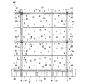
次に、上記の仕切壁部材20、30を備える屋根緑化構造体A1の一例を図5〜図7を用いて説明する。図2には図示されないが、緯仕切壁部材20と経仕切壁部材30で包囲される区画内における立ちはぜ突条4・・には、所定間隔で適数のクランプ60が固定される。前記したように、クランプ60のクランプ片61は、前記第1の水平部62b,垂直部64,第2の水平部65で形成される断面コ字状空間を有しており、隣接するクランプ60の前記断面コ字状空間内に端縁を差し込むようにして発泡樹脂製断熱板50・・を取り付ける(例えば、図6及び図7を参照)。それにより、立ちはぜ折板屋根Rの上面は、全体が発泡樹脂製断熱板50で覆われた状態となり、平坦面が形成される。そして、その上に、適宜の従来知られた複数枚の保水排水基盤材10が敷き詰められて固定され、保水排水基盤材10の上に、土壌流出防止のための透水シート11を介して、適宜の植物層Bが配置されて、屋根緑化構造体A1とされる。
Next, an example of roof greening structure A1 provided with said
緯仕切壁部材20及び経仕切壁部材30は、図6及び図7に示すように、植物層Bよりも上方に突出しており、植物層Bを屋根勾配方向及び屋根横幅方向に所定間隔をおいて仕切り、複数の領域に区画している。上端片部22、32は、植物層Bの上方に所定距離だけ離間した高さ位置で植物層Bと平行に延在しており、植物層Bの上面に対向している。これにより、屋根緑化構造体A1の植物層Bは、経仕切壁部材30によって屋根横幅方向であるY方向に区画され、また、緯仕切壁部材20によって屋根勾配方向であるX方向に区画されている。本実施の形態では、Y方向に1メートル間隔を有し、X方向に2メートル間隔を有するように設けられている。また、上端片部22、32の高さ位置は、植物層Bから約10センチメートル程度高くなるように設定されている。
As shown in FIGS. 6 and 7, the weft
緯仕切壁部材20、経仕切壁部材30は、立ちはぜ突条4に固定されたクランプ60を利用して立ちはぜ折板屋根Rに堅固に固定されており、これら緯仕切壁部材20、経仕切壁部材30の上を歩行する歩行者等の荷重を十分に支えることができるようになっている。
The weft
また、上端片部22、32の横幅は、その上を作業者等が歩行できる大きさ(本実施の形態では約5センチメートル)に設定されている。従って、これら緯仕切壁部材20、経仕切壁部材30の上を歩行することができ、植物層Bの植物を傷つけずに植物の管理作業等を行うことができる。
Moreover, the horizontal width of the
なお、図示の例において、保水排水基盤材10は、発泡樹脂の成形品であり、図示されないが、保水用空間と植物層B等の支持体を有し、周壁部には互いに嵌合する接続用凹凸部や溢流部が形成されている。
In the illustrated example, the water retention /
図8は上記した構造による植物層Bの延焼防止方法を説明する模式図であり、図8(a)は本実施の形態を示し、図8(b)は従来技術を示すものである。例えば、立ちはぜ折板屋根Rの屋根勾配方向に沿って勾配方向下側から勾配方向上側に向かって(図中に太矢印で示す方向である左側から右側に向かって)風が吹いている状況で、風上に位置する植物層B、103に火がついた場合に、図8(b)に示す従来技術では、隔絶部100が風上の植栽基盤101の土壌102と風下の植栽基盤111の土壌112とを仕切っているだけであるので、風上の植栽基盤101の植物層103を燃やしている火炎や火の粉(図中で細矢印で示す)が風下(勾配方向上側)の植栽基盤111の植物層113に移るのを防ぐことはできず、隔壁部100によって延焼を止めることはできない。
FIG. 8 is a schematic diagram for explaining a method for preventing the spread of the plant layer B with the above-described structure. FIG. 8 (a) shows the present embodiment, and FIG. 8 (b) shows the prior art. For example, the wind is blowing from the lower gradient direction toward the upper gradient direction along the roof gradient direction of the standing folded plate roof R (from the left side to the right side, which is the direction indicated by the thick arrow in the figure). In the situation, when the plant layers B and 103 located on the windward side are lit, in the conventional technique shown in FIG. 8 (b), the
一方、図8(a)に示す本実施の形態では、緯仕切壁部材20が風向きに対して直交する方向に延在し且つ植物層Bよりも上方の高さ位置まで突出しているので、風上の植物層Bを燃やしている火炎を緯仕切壁部材20でせき止めて、風下の植物層Bに移るのを防ぐことができる。特に、緯仕切壁部材20は、風上に向かって上端片部22が折り返して設けているので、風に煽られた火炎や火の粉を風上に向かって折り返して、風上の領域内に留めることができる。従って、風下への延焼を効果的に防ぐことができる。
On the other hand, in the present embodiment shown in FIG. 8A, the weft
なお、仕切壁部材20、30の形状は、上記した断面コ字型の形状に限定されるものではなく、隣接する領域への延焼を防ぐことができる形状であればよい。従って、例えば図9に示す変形例のように、平板状の仕切壁部70をクランプ60から上方に向かって植物層Bよりも上方の高さ位置まで一直線状に突出させる構成としてもよい。このように仕切壁部材70を平板形状の部材によって構成することによって、略コ字型の断面形状が有する仕切壁部材20、30よりも材料費を安価にすることができ、コストを低減することができる。また、上記した実施の形態では、仕切壁部20、30、70の高さが植物層Bよりも高い場合を例に説明したが、植物層Bの高さと同一の高さであってもよい。
In addition, the shape of the
図10は、第2実施の形態を説明する断面図である。なお、第1実施の形態と同様の構成要素には同一の符号を付することでその詳細な説明を省略する。本実施の形態では、屋上緑化構造体A2の延焼防止構造について説明する。建物の屋上には、コンクリートスラブSの上面を覆うように根の浸入を防止するための耐根シート12が敷き詰められて、平坦面が形成されている。そして、その平坦面の上に、適宜の従来知られた複数枚の保水排水基盤材10が並べて配置される。そして、保水排水基盤材10の上に、土壌流出防止のための透水シート11を介して適宜の植物層Bが配置されて、屋上緑化構造体A2とされる。
FIG. 10 is a sectional view for explaining the second embodiment. The same components as those in the first embodiment are denoted by the same reference numerals, and detailed description thereof is omitted. In the present embodiment, the fire spread prevention structure of the rooftop greening structure A2 will be described. On the rooftop of the building, a root-
仕切壁部材40は、保水排水基盤材10の継ぎ目に沿って配置されており、屋上緑化構造体A2を複数の領域に区画している。仕切壁部材40は、第1実施の形態における仕切壁部材20、30と同様に断面が略コ字型の長尺部材によって構成されており、一対の縦壁部41、41を互いに接面させて、各上端片部42、42及び各下端片部43、43が互いに離反する背中合わせの状態で、互いに隣り合う保水排水基盤材10の間に挟まれる形で配置されている。仕切壁部材40の下端片部43は、発泡樹脂製断熱板50の上面に接着剤等で固定されている。なお、仕切壁部材40は固定されていなくてもよい。仕切壁部材40の縦壁部41は、植物層Bよりも上方の高さ位置まで突出している。
The
上記構成を有する屋上緑化構造体A2によれば、仕切壁部材40を容易に設置することができ、設置工事を簡単化でき、低コストで施工できる。また、上記した屋根緑化構造体A1と同様に、仕切壁部材40が植物層Bよりも上方の高さ位置まで突出しているので、例えば風上に位置する植物層Bに火がついた場合に、火炎をせき止めて風下の植物層Bに移るのを防ぐことができる。従って、風下への延焼を効果的に防ぐことができる。
According to the roof tree planting structure A2 having the above configuration, the
以上、各実施の形態について図面を用いて詳述したが、具体的な構成はこれら各実施の形態に限定されるものではなく、本発明の要旨を逸脱しない範囲における設計変更等があっても、それらは本発明に含まれるものである。 The embodiments have been described in detail with reference to the drawings. However, the specific configuration is not limited to these embodiments, and even if there is a design change or the like without departing from the scope of the invention. These are included in the present invention.
1 山形部
2 頭頂部
3 屋根板
10 保水排水基盤材(緑化基盤)
11 透水シート
12 耐根シート
20 緯仕切壁部材
21 縦壁部
22 上端片部
30 経仕切壁部材
31 縦壁部
32 上端片部
40 仕切壁部材
41 縦壁部
42 上端片部
50 発泡樹脂製断熱板
60 クランプ
70 仕切壁部(第2実施の形態)
A1 屋根緑化構造体(緑化構造体)
A2 屋上緑化構造体(緑化構造体)
R 立ちはぜ折板屋根
DESCRIPTION OF
DESCRIPTION OF
A1 roof greening structure (greening structure)
A2 Rooftop greening structure (greening structure)
R Standing folded plate roof
Claims (5)
前記緑化構造体の植物層を複数の領域に区画する耐火性或いは難燃性の仕切壁部を有し、
該仕切壁部は、上下に延在して前記植物層の下端から前記植物層よりも上方の高さ位置まで突出する縦壁部と、該縦壁部の上端から互いに離反する方向に突出する一対の上端片部とを有することを特徴とする緑化構造体の延焼防止構造。 In the fire spread prevention structure of the greening structure laid on the roof or roof,
Having a fire-resistant or flame-retardant partition wall that partitions the plant layer of the greening structure into a plurality of regions;
The partition wall portion extends vertically and protrudes from the lower end of the plant layer to a height position above the plant layer, and protrudes in a direction away from the upper end of the vertical wall portion. A structure for preventing fire spread of a greening structure, comprising a pair of upper end pieces.
Priority Applications (1)
| Application Number | Priority Date | Filing Date | Title |
|---|---|---|---|
| JP2008196586A JP5183345B2 (en) | 2008-07-30 | 2008-07-30 | Structure to prevent the spread of greening structures |
Applications Claiming Priority (1)
| Application Number | Priority Date | Filing Date | Title |
|---|---|---|---|
| JP2008196586A JP5183345B2 (en) | 2008-07-30 | 2008-07-30 | Structure to prevent the spread of greening structures |
Publications (3)
| Publication Number | Publication Date |
|---|---|
| JP2010029141A JP2010029141A (en) | 2010-02-12 |
| JP2010029141A5 JP2010029141A5 (en) | 2011-02-17 |
| JP5183345B2 true JP5183345B2 (en) | 2013-04-17 |
Family
ID=41734395
Family Applications (1)
| Application Number | Title | Priority Date | Filing Date |
|---|---|---|---|
| JP2008196586A Active JP5183345B2 (en) | 2008-07-30 | 2008-07-30 | Structure to prevent the spread of greening structures |
Country Status (1)
| Country | Link |
|---|---|
| JP (1) | JP5183345B2 (en) |
Families Citing this family (1)
| Publication number | Priority date | Publication date | Assignee | Title |
|---|---|---|---|---|
| JP5489799B2 (en) * | 2010-03-18 | 2014-05-14 | 住友林業株式会社 | Rooftop greening system |
Family Cites Families (8)
| Publication number | Priority date | Publication date | Assignee | Title |
|---|---|---|---|---|
| JP3590616B2 (en) * | 2002-02-08 | 2004-11-17 | 東興建設株式会社 | Method of preventing fire from spreading on artificial soil and its structure |
| JP4113789B2 (en) * | 2003-02-14 | 2008-07-09 | ロンシール工業株式会社 | Parting material for greening and its construction method |
| JP2005080594A (en) * | 2003-09-09 | 2005-03-31 | Sato Kogyo Co Ltd | Planting base and engineering method for greening rooftop |
| JP2006025768A (en) * | 2004-07-21 | 2006-02-02 | Okumura Corp | Folded plate roof-greening system |
| JP2007051478A (en) * | 2005-08-18 | 2007-03-01 | Nippon Steel & Sumikin Coated Sheet Corp | Roof attached with functional panel |
| JP2007089412A (en) * | 2005-09-27 | 2007-04-12 | Sekisui Plastics Co Ltd | Planting end material, planting end frame structure, and greening structure using the same |
| JP2008022723A (en) * | 2006-07-18 | 2008-02-07 | Kanawa Kogyo:Kk | Installation member and metal fitting |
| JP5063993B2 (en) * | 2006-11-20 | 2012-10-31 | 積水化成品工業株式会社 | Parting material fixing structure |
-
2008
- 2008-07-30 JP JP2008196586A patent/JP5183345B2/en active Active
Also Published As
| Publication number | Publication date |
|---|---|
| JP2010029141A (en) | 2010-02-12 |
Similar Documents
| Publication | Publication Date | Title |
|---|---|---|
| US20080260993A1 (en) | Moisture drainage product having limited bearing surface, wall system incorporating such and method therefore | |
| JP5183345B2 (en) | Structure to prevent the spread of greening structures | |
| JP5004532B2 (en) | Fixed structure of greening base material to standing folded plate roof and standing folded plate roof greening structure using the fixed structure | |
| JP2002095348A (en) | Roof-greening structure | |
| JP5100464B2 (en) | Structure for fixing parting material to folded-plate roof and folded-plate roof greening structure with the same | |
| JP4955317B2 (en) | Fixed structure of greening base material to standing folded plate roof and standing folded plate roof greening structure using the fixed structure | |
| JP2009293201A (en) | Supporting structure of heat insulation unit | |
| JP4106065B2 (en) | Green roof | |
| JP5489799B2 (en) | Rooftop greening system | |
| JP5063993B2 (en) | Parting material fixing structure | |
| JP3790757B2 (en) | Green roof structure | |
| JP2006274759A (en) | Fixing structure of seeding and planting base material to folded-plate roof and folded-plate roof seeding and planting structure using the fixing structure | |
| JP2010138545A (en) | Roof seeding and planting structure | |
| JP4577906B2 (en) | Greening structure of sloped roof | |
| JP7399496B2 (en) | Eave ventilation structure and eave ventilation components | |
| JPH11127685A (en) | Partition structure for rooftop greening | |
| JPS6318674Y2 (en) | ||
| BR102013007092A2 (en) | Molded ridge tile made of bitumen-impregnated cellulose and an application thereof | |
| JP7403749B2 (en) | Water-cooled steel plate fire fence | |
| JP5913864B2 (en) | Roof safety member | |
| JP2008184796A (en) | Greening structure of sloped roof | |
| JP2008263794A (en) | Parapet greening device | |
| JP2023049967A (en) | Eave structure | |
| JP3207899U (en) | Snow melting device and snow melting device set | |
| JPH049777Y2 (en) |
Legal Events
| Date | Code | Title | Description |
|---|---|---|---|
| A521 | Written amendment |
Free format text: JAPANESE INTERMEDIATE CODE: A523 Effective date: 20101222 |
|
| A621 | Written request for application examination |
Free format text: JAPANESE INTERMEDIATE CODE: A621 Effective date: 20110111 |
|
| A977 | Report on retrieval |
Free format text: JAPANESE INTERMEDIATE CODE: A971007 Effective date: 20120221 |
|
| A131 | Notification of reasons for refusal |
Free format text: JAPANESE INTERMEDIATE CODE: A131 Effective date: 20120228 |
|
| A521 | Written amendment |
Free format text: JAPANESE INTERMEDIATE CODE: A523 Effective date: 20120427 |
|
| TRDD | Decision of grant or rejection written | ||
| A01 | Written decision to grant a patent or to grant a registration (utility model) |
Free format text: JAPANESE INTERMEDIATE CODE: A01 Effective date: 20130108 |
|
| A61 | First payment of annual fees (during grant procedure) |
Free format text: JAPANESE INTERMEDIATE CODE: A61 Effective date: 20130115 |
|
| R150 | Certificate of patent or registration of utility model |
Ref document number: 5183345 Country of ref document: JP Free format text: JAPANESE INTERMEDIATE CODE: R150 Free format text: JAPANESE INTERMEDIATE CODE: R150 |
|
| FPAY | Renewal fee payment (event date is renewal date of database) |
Free format text: PAYMENT UNTIL: 20160125 Year of fee payment: 3 |