JP5179515B2 - Fastening device with retractable operating arm and instrument comprising such a device - Google Patents
Fastening device with retractable operating arm and instrument comprising such a device Download PDFInfo
- Publication number
- JP5179515B2 JP5179515B2 JP2009550308A JP2009550308A JP5179515B2 JP 5179515 B2 JP5179515 B2 JP 5179515B2 JP 2009550308 A JP2009550308 A JP 2009550308A JP 2009550308 A JP2009550308 A JP 2009550308A JP 5179515 B2 JP5179515 B2 JP 5179515B2
- Authority
- JP
- Japan
- Prior art keywords
- spanner
- clamping
- fastening
- tightening
- nut
- Prior art date
- Legal status (The legal status is an assumption and is not a legal conclusion. Google has not performed a legal analysis and makes no representation as to the accuracy of the status listed.)
- Expired - Fee Related
Links
Images


Classifications
-
- B—PERFORMING OPERATIONS; TRANSPORTING
- B25—HAND TOOLS; PORTABLE POWER-DRIVEN TOOLS; MANIPULATORS
- B25B—TOOLS OR BENCH DEVICES NOT OTHERWISE PROVIDED FOR, FOR FASTENING, CONNECTING, DISENGAGING OR HOLDING
- B25B13/00—Spanners; Wrenches
- B25B13/02—Spanners; Wrenches with rigid jaws
- B25B13/08—Spanners; Wrenches with rigid jaws of open jaw type
-
- B—PERFORMING OPERATIONS; TRANSPORTING
- B25—HAND TOOLS; PORTABLE POWER-DRIVEN TOOLS; MANIPULATORS
- B25B—TOOLS OR BENCH DEVICES NOT OTHERWISE PROVIDED FOR, FOR FASTENING, CONNECTING, DISENGAGING OR HOLDING
- B25B13/00—Spanners; Wrenches
- B25B13/48—Spanners; Wrenches for special purposes
-
- B—PERFORMING OPERATIONS; TRANSPORTING
- B27—WORKING OR PRESERVING WOOD OR SIMILAR MATERIAL; NAILING OR STAPLING MACHINES IN GENERAL
- B27B—SAWS FOR WOOD OR SIMILAR MATERIAL; COMPONENTS OR ACCESSORIES THEREFOR
- B27B17/00—Chain saws; Equipment therefor
-
- B—PERFORMING OPERATIONS; TRANSPORTING
- B27—WORKING OR PRESERVING WOOD OR SIMILAR MATERIAL; NAILING OR STAPLING MACHINES IN GENERAL
- B27B—SAWS FOR WOOD OR SIMILAR MATERIAL; COMPONENTS OR ACCESSORIES THEREFOR
- B27B17/00—Chain saws; Equipment therefor
- B27B17/14—Arrangements for stretching the chain saw
Description
本発明は、引き込み式の操作アームを備えた締め付け装置に関する。本発明は、また、この締め付け装置を備えた器具、たとえば携帯用工具に関し、特に携帯用チェーンソーに関する。 The present invention relates to a fastening device provided with a retractable operation arm. The invention also relates to an instrument provided with this clamping device, for example a portable tool, in particular a portable chain saw.
2個の部品の間に締め付け応力を加えるためにねじ切りロッドにねじ止めされるねじまたはナットを用いることは通常行われている。ねじナットシステムを用いて組み立てられる部品は、着脱式であるという長所を有する。しかしながら、その部品を分解し、後でまた組み立てるには、スパナまたはドライバー等の独立した工具を用いてナットまたはねじを緩めてから、この同じ工具を用いてこれらを再び締め付けることが必要である。ところで、このような工具については常に所持しているとは限らず、ナットまたはねじを緩め、および/または締め付ける必要性があるときにちょうど工具を持っていないことがある。 It is common practice to use a screw or nut that is screwed onto a threaded rod to apply a clamping stress between the two parts. Parts assembled using a screw nut system have the advantage of being detachable. However, to disassemble the parts and reassemble them later, it is necessary to loosen the nuts or screws with an independent tool such as a spanner or screwdriver and then tighten them again with this same tool. By the way, such tools are not always possessed and may not have the tools when there is a need to loosen and / or tighten nuts or screws.
さらに、操作の間にねじまたはナットのヘッドからドライバーまたはスパナが運悪く離れてしまうことがよくある。このため、ナットまたはねじを締めたり緩めたりするには、往々にして、技量と熟練とを組み合わせる術を心得ていることが必要である。 In addition, the driver or spanner often unluckily leaves the screw or nut head during operation. For this reason, in order to tighten or loosen a nut or screw, it is often necessary to know how to combine skill and skill.
ねじナット装置は、一般に、ガイドバーを所望の位置に締め付けて固定することによりガイドバーの張力調整または新しいチェーンの取付を可能にするために、携帯用のチェーンソーに装備される。 The screw nut device is generally installed in a portable chainsaw to allow tension adjustment of the guide bar or installation of a new chain by tightening and fixing the guide bar in a desired position.
このような用途では、特に、チェーンソーのチェーンの張力調整の実施が必要な場合がある屋外での工具の使用中、締め付けナットまたはねじを緩めたり再び締め付けたりするための専用の工具を作業者が常に手の届く範囲に所持すべきであることが分かる。 In such applications, the operator may need a special tool to loosen or retighten the tightening nut or screw, especially during outdoor use of the chain saw where it may be necessary to perform chain tensioning. It can be seen that it should always be within reach.
この制約を解消するために、ねじナットシステムを用いてチェーンソーのガイドチェーンを締め付ける装置が提案されており(独国実用新案第29909645号明細書)、それによれば、このシステムのナットは操作スパナに常時しっかり止められており、スパナは、使用していないときはニュートラル位置で工具ケースに対して折り畳むことができる。この装置によれば、ナットのヘッドの下に回転リングが配置されていて、スパナは、ナットの軸の垂直軸を中心として、ナットに対してオフセットされるように、一定の揺動性を伴ってこの回転リングに固定される。他方で、ナットのヘッドは2個の半径方向の溝を備えており、スパナは1個の歯を備えていて、上記スパナの揺動位置に応じて、この歯を上記溝の一つと係合可能にすることによりナットをいずれかの方向に回転駆動可能にし、または上記溝から解放可能にすることによりナットを中心としてスパナを自在に回転可能にしている。 In order to overcome this limitation, a device for tightening a chain saw guide chain using a screw nut system has been proposed (German Utility Model No. 29909645). According to this, the nut of this system is used as an operation spanner. Always secured, the spanner can be folded against the tool case in the neutral position when not in use. According to this device, a rotating ring is disposed under the head of the nut, and the spanner has a certain swinging property so as to be offset with respect to the nut about the vertical axis of the nut. The lever is fixed to the rotating ring. On the other hand, the nut head has two radial grooves, and the spanner has one tooth, which is engaged with one of the grooves according to the swing position of the spanner. By enabling the nut, the nut can be driven to rotate in either direction, or by releasing the nut from the groove, the spanner can be freely rotated around the nut.
この装置は、ナットの回転運動の前または収納位置にスパナを配置する動きの前に、場合に応じて必ず連動操作または連動解除操作が必要であり、ユーザはこれを即座に理解することができない。 This device always requires an interlocking operation or an interlocking releasing operation before the rotational movement of the nut or before the movement of placing the spanner in the storage position, and the user cannot immediately understand this operation. .
本発明は、上記の様々な制約によって生じる問題に対する解決方法を提案することを目的とする。 The present invention aims to propose a solution to the problem caused by the various constraints described above.
本発明によれば、この目的は、ねじナットタイプの締め付け装置により達成され、この締め付け装置は、回転駆動可能な締め付け部材と、操作アームを備えて締め付け部材を連動させるスパナとを含んでおり、上記スパナおよび締め付け部材が結合装置により結合され、結合装置は、上記締め付け部材のねじ止め軸に垂直な揺動軸を中心として締め付け部材に対してスパナが揺動して上記ねじ止め軸にほぼ垂直な休止位置に締め付け部材を配置できるように、また、上記ねじ止め軸を中心として締め付け方向または緩める方向にスパナが締め付け部材を回転駆動できるように、または、締め付け操作の終了時に上記締め付け部材を固定した後で、締め付け方向とは反対の方向に少なくとも170°の角度ストローク範囲にわたって上記ねじ止め軸を中心として締め付け部材に対してスパナを自在に回転できるように、構成されている。 According to the present invention, this object is achieved by a screw nut type tightening device, which includes a tightening member that can be rotationally driven, and a spanner that includes an operating arm and interlocks the tightening member, The spanner and the fastening member are coupled by a coupling device, and the coupling device is substantially perpendicular to the screwing shaft by swinging the spanner with respect to the clamping member about a rocking shaft perpendicular to the screwing shaft of the clamping member. So that the tightening member can be placed in the rest position, and the spanner can rotate the tightening member in the tightening direction or loosening direction around the screwing shaft, or fix the tightening member at the end of the tightening operation After that, the screwing is performed over an angular stroke range of at least 170 ° in the direction opposite to the tightening direction. Spanner so that it can rotate freely relative to the fastening member about the axis, is formed.
本発明によれば、締め付け装置の操作は、上記締め付け装置の締め付け部材(ねじまたはナット)を締め付けたり緩めたりするために如何なる外部工具の使用も必要としない。締め付け部材に結合されるスパナは、得られる締め付けを変えることなく所定の休止位置、たとえば器具の使用を妨げないように器具のケースに対する折り畳み位置に配置可能にしながら締め付け部材の回転駆動を可能にする。さらに、この操作は簡単かつ迅速である。 According to the invention, the operation of the clamping device does not require the use of any external tool to tighten or loosen the clamping member (screw or nut) of the clamping device. A spanner coupled to the clamping member allows rotational driving of the clamping member while allowing it to be placed in a predetermined rest position, for example, a folded position relative to the instrument case, without altering the resulting clamping. . Furthermore, this operation is simple and quick.
有利な実施形態によれば、操作スパナに結合されるねじナットシステムの回転締め付け部材が、上記システムのナットから構成されている。 According to an advantageous embodiment, the rotary tightening member of the screw nut system coupled to the operating spanner comprises the nut of the system.
有利には、結合装置の締め付け部材および操作スパナは、このスパナの回転に際して、一方で、スパナが角度ストローク範囲の第1の端にあるときは締め付け部材のねじ止め方向に、他方で、スパナが角度ストローク範囲の第2の端にあるときは締め付け部材の緩み方向に、相互接触する手段をそれぞれ備えている。 Advantageously, the fastening member and the operating spanner of the coupling device, on the one hand, rotate on the one hand when the spanner is at the first end of the angular stroke range and in the screwing direction of the fastening member, on the other hand When at the second end of the angular stroke range, means for contacting each other are provided in the loosening direction of the fastening member.
好適な実施形態によれば、駆動スパナと締め付け装置との結合手段が、
−回転締め付け部材の本体の円筒形の外面に設けられ、上記回転締め付け部材のねじ止め軸に平行に配向された駆動ストッパが底に収容される、環状溝と、
−上記締め付け部材の本体が内部に収容され、上記締め付け部材の環状溝に通じる直径方向に向かい合った2個の孔を含む、筒状の回転キャップと、
−駆動スパナのヘッドが2個の分枝を有するフォークの形状に構成され、これらの分枝の端が、互いに向かって湾曲または形成されるとともに、回転キャップの直径方向に向かい合った孔に回転可能に係合され、これらの湾曲端の少なくとも一方が、上記溝を通って延びて回転締め付け部材の駆動ストッパと接するように寸法決定される、上記ヘッドの構成とを含む。
According to a preferred embodiment, the coupling means between the drive spanner and the clamping device comprises:
An annular groove provided on the bottom of a drive stopper provided on the cylindrical outer surface of the body of the rotary fastening member and oriented parallel to the screwing shaft of the rotary fastening member;
A cylindrical rotating cap, wherein the body of the clamping member is housed therein and includes two diametrically opposed holes leading to the annular groove of the clamping member;
The head of the drive spanner is configured in the shape of a fork with two branches, the ends of these branches being curved or formed towards each other and rotatable in diametrically opposed holes in the rotating cap And at least one of these curved ends extending through the groove and dimensioned to contact the drive stop of the rotary clamping member.
別の有利な特徴によれば、駆動フォークの第2の分枝の湾曲端は、スパナをねじ止め軸を中心として締め付け部材に対して旋回する時に、締め付け部材の駆動ストッパに接しないように寸法決定される。 According to another advantageous feature, the curved end of the second branch of the drive fork is dimensioned so that it does not contact the drive stop of the clamping member when the spanner is pivoted with respect to the clamping member about the screw shaft. It is determined.
締め付け装置の別の有利な特徴は、上記結合装置が、スパナと締め付け部材とを分解不能に結合することとすることができる。 Another advantageous feature of the clamping device is that the coupling device couples the spanner and the clamping member in a non-decomposable manner.
有利には、スパナと締め付け部材との分解不能な結合が、上記分枝を互いに向かって形態変形させて、キャップの穴にこれらの分枝を係合することで得られる。 Advantageously, an indestructible connection between the spanner and the clamping member is obtained by deforming the branches towards each other and engaging the branches in the cap holes.
好適には、上記結合装置は、少なくとも締め付け部材による締め付けがないとき、スパナと締め付け部材とを分解可能に結合する。 Suitably, the said coupling | bonding apparatus couple | bonds a spanner and a clamping member so that decomposition | disassembly is possible at least when there is no clamping | tightening by a clamping member.
好適には、締め付け部材は、環状溝に上記分枝の少なくとも一方を通過させるように上記環状溝に側面から接近する切り込みを含んでおり、上記キャップの上記孔の一方が、上記分枝の一方を通過させるための開放端を有するスリットの形状を呈する。 Preferably, the clamping member includes a notch approaching from the side of the annular groove so that at least one of the branches passes through the annular groove, and one of the holes of the cap is one of the branches. The shape of the slit which has an open end for letting go through is exhibited.
有利には、スパナは、延長部を備えた操作アームを含んで、操作アームが、この延長部と共に長さ調整可能な伸縮式のスリーブを形成し、上記延長部が、伸縮式スリーブの収縮位置と延伸位置との間で操作アームに沿って移動可能である。 Advantageously, the spanner comprises an operating arm with an extension, the operating arm together with the extension forming a telescopic sleeve of adjustable length, the extension being in the contracted position of the telescopic sleeve. And can be moved along the operating arm between the extended position and the extended position.
好適には、操作アームの少なくとも一部が、磁気材料で形成されている。 Preferably, at least a part of the operating arm is made of a magnetic material.
本発明は、また、上記のような締め付け装置を含むことを特徴とする器具を目的とする。 The present invention is also directed to an instrument characterized in that it includes a clamping device as described above.
有利な実施形態によれば、この器具は、エンドレスソーチェーンならびにこのチェーンのためのガイドバーとを含むチェーンソーから構成され、ガイドバーのロック装置が上記締め付け装置を含む。 According to an advantageous embodiment, the device consists of a chain saw comprising an endless saw chain as well as a guide bar for the chain, the guide bar locking device comprising the clamping device.
有利には、器具が、ねじ止め軸を中心として予め決められた角方向の位置に締め付け装置のスリーブを収納するゾーンを含む。 Advantageously, the instrument includes a zone for receiving the sleeve of the clamping device in a predetermined angular position about the screw shaft.
好適には、器具は、引き込み位置で上記収納ゾーンのレベルにスリーブの固定磁石を含む。 Preferably, the instrument includes a fixed magnet for the sleeve at the level of the storage zone in the retracted position.
本発明は、例としてのみ挙げられ、添付図面を参照しながらなされる以下の説明を読めば、いっそう理解される。 The invention will be better understood on reading the following description given by way of example only and with reference to the accompanying drawings, in which:
上記の図面を参照することにより、限定的ではない本発明による締め付け装置の有利な実施形態を説明する。 Non-limiting advantageous embodiments of the clamping device according to the invention will be described with reference to the above drawings.
また、以下、チェーンソー設備に適用される本発明の特に有利な用途について説明するが、請求されている締め付け装置は、締め付け調整を頻繁に実施しなければならない他の工具または機械にも同様に適用可能であり、特に屋外で使用可能な器具に対して適用可能であることを強調しておく。 In the following, a particularly advantageous application of the present invention as applied to a chain saw facility will be described, but the claimed clamping device is equally applicable to other tools or machines that must be tightened frequently. It is emphasized that this is possible and is particularly applicable to equipment that can be used outdoors.
図1に示した携帯用のチェーンソー1は、部分的に示したエンドレスソーチェーン2と、このチェーン2を保持および支持するガイドバー3とを含む。図1に参照符号4で全体を示した締め付け装置4は、このガイドバー3と保護ケース5とをジョー5Aと組立本体6との間で締め付けている。
The portable chain saw 1 shown in FIG. 1 includes an endless saw chain 2 partially shown, and a
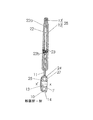
図2に示した締め付け装置4は、たとえば1個のねじのねじ切りロッドからなるねじ切りロッド8にねじ止めされるように構成されたナット7を含む。この締め付け装置は、さらに、操作キー11と、上記操作キー11にナット7を結合可能にする結合装置(参照符号9で全体を示す)とを含む。
The
ナット7は、このナット7のねじ止め軸すなわち、ナット7を締めるときと緩めるときにこの軸を中心として回転する軸であるX−X’軸を有するねじ穴13を穿孔されている。ナット7は、環状の側面溝14をその周辺面15に備えている。
The
この周辺溝15は円筒形であり、X−X’軸に中心を合わせた円形断面を有する。
The
ナット7は、端から端まで側面溝14を貫通するピン16を備える。
The
ナット7は、上記ナットの周辺溝14に通じる直径方向に向かい合った2個の孔26a、26bを備えた、筒状の回転被覆キャップ10をかぶせられる。
The
スパナ11は平らで、有利には、鋼板から構成可能である。スパナは、ナット7に連結されるヘッド18が延長されたアーム17を含む。ヘッド18は、湾曲してから互いに向かい合う2個の分枝19、20を有するフォークの形状をしている。これらの分枝の一方(分枝19)は、他方(分枝20)よりも長く、その端部分は、スパナの回転方向に応じてピン16の片側または反対側に当接するフィンガ21を構成する。
The
キャップ10は円筒形のスカート24を含み、このスカートを端壁25が閉じている。分枝19、20を通すための2個の横穴26a、26bが、互いに対向してスカート24に穿孔されている。孔の一方(孔26a)は、側面で閉じた円形とすることができる。
The
実施形態によれば、第2の孔(26b)はスリットの形状を有し、その一端が、孔26aの軸線上にあり、他端が、キャップ10の背面でキャップの縁に通じている。
According to the embodiment, the second hole (26 b) has a slit shape, one end of which is on the axis of the
分枝19および20の末端部分は同軸であり、孔26a、26bに係合されることによって、キャップ10にスパナ11を揺動式に取り付けるときの不連続シャフトを一緒に形成する。スパナ11の揺動軸Y−Y’は、ねじ止め軸X−X’に垂直であり、上記Y−Y’軸とX−X’軸は交差する。
The end portions of the
図3〜図5から分かるように、キャップ10は、その回転軸がねじ止め軸X−X’と一致するようにナット7に回転式に取り付けられる。分枝19、20は、周辺溝14に入り、それによってスパナ11およびキャップ10をナット7に固定する。上記の第1の機能は揺動式の取付シャフトを形成することであったが、このようにして、分枝は第2の機能を果たすという長所を有する。
As can be seen from FIGS. 3 to 5, the
この点に関して、分枝19は、その端21を介して、同様に、ナット7を回転駆動させるフィンガの機能を果たす。分枝19と20により行われる機能を合わせることによって、有利には締め付け装置4が簡素化され、その小型化が促される。
In this respect, the
切り込み27は、ナット7の溝14を画定する後壁に横方向に設けられ、この切り込みは上記溝に通じている。
The
結合装置の諸要素を組み立てるには、ナット7をキャップ10内に配置する。その後、分枝19を孔26aとナットの溝14に入れる。最後に、他方の分枝をスリット26bの底に向かってスライドさせ、それと同時に、この分枝20を切り込み27を通過させながら周辺溝14に係合する(図6)。この組立方式によって、スパナ11とナット7とを分解式に結合することができる。
To assemble the elements of the coupling device, the
別の実施形態によれば、ナット7は、切り込み27を備えていなくてもよく、その一方で孔26bは、孔26aと同じ円形形状にすることができる。そうした場合には、分枝19と20を、互いに向かって形態変形させながら孔26a、孔26b、および溝14に挿入することができる。この場合、スパナと締め付け部材との分解不能な結合が実現される。
According to another embodiment, the
有利な実施形態によれば、スパナの操作アームの長さは調整可能である。この場合、操作アームは、伸縮式に組み立てられる2つの要素から構成され、すなわち連結ヘッド18を備えたアーム17に延長部12がスライド式に組み立てられる。
According to an advantageous embodiment, the length of the operating arm of the spanner is adjustable. In this case, the operation arm is composed of two elements that are assembled in a telescopic manner, that is, the
この延長部が、たとえばプラスチック材料等のあらゆる適切な剛性材料で製造可能なハンドルを構成する。内部アーム17は、ボルト23のロッドが通過する長手方向のスリット22を備えている。スリット22は2個の端部を有し、各端部でその縁がボルト23のロッドのための2個のストッパ22a、22bの一方を形成する。ボルト23とストッパ22aは、アーム17にハンドル12を固定する相補的な手段を構成する。
This extension constitutes a handle that can be made of any suitable rigid material, for example a plastic material. The
図3から分かるように、分枝20は分枝19とは異なって、連結されずにピン16の場所を乗り越えることができる。
As can be seen from FIG. 3, the
スパナ11は、図7にαで示した角度ストローク範囲にわたってナット7に対して自在に回転することができる。こうしたストローク範囲すなわちストローク角度αの一端で、フィンガ21はピン16に当接し、それによって、スパナ11をナット7に、このナット7のねじ止め方向F1に連結する。図7に実線で示したフィンガ21がそれにあたる。フィンガ21は、また、ストローク範囲またはストローク角度αの他端で、ピン16の反対面に当接することによってスパナ11をナット7に連結するが、しかし、これは、ナット7を緩める方向F2に行われる。図7に細い鎖線で示したスパナ11のフィンガ21がそれにあたる。従って、ピン16は、フィンガ21のダブルストッパを形成する。
The
図示された例では、角度ストローク範囲αが340°以上にわたって広がっているが、これは有利である。しかし、広がり方を少なくしてもよい。とはいえ、好適には、角度ストローク範囲または角度αは、少なくとも170°である。 In the example shown, the angular stroke range α extends over 340 ° or more, which is advantageous. However, the spread may be reduced. However, preferably, the angular stroke range or angle α is at least 170 °.
ハンドル12は、アーム17で長手方向にスライド可能であるという意味で延長部を形成する。言い換えると、アーム17とハンドル12は、図4に収縮位置で示し、図6に伸張位置で示した、伸縮式のスリーブ28を一緒に形成する。
The
工具のケース5は、引き込み位置でスパナの操作アーム17または伸縮式スリーブ28を収容するためのハウジング29を側面に備えている。固定手段により、スパナの操作アーム17または伸縮式スリーブ28を引き込み位置で工具のケース5に保持することができる。たとえば、ハウジング29の底には、操作アーム17またはスリーブ28を休止引き込み位置に固定可能にする磁石が配置されており、この磁石は、図8と図10に示すように参照符号30で示されている。
The
ナット7をねじ止めするには、ねじ止め軸X−X’を中心として方向F1にスパナ11を回転させ(図7)、そのフィンガ21がピン16に接触してから上記ピン16を介してナット7を連動させるようにする。
In order to screw the
図7と図8では、適切な締め付け力が得られた瞬間に対応する位置にスパナ11があるものとみなす。その場合、ハウジング29にスリーブ28を引き込むことが必要であるが、これは、軸X−X’を中心とするハウジング29の角度位置が、ナット7の締め付けの終わりに角度ストローク範囲αにある場合は容易に行われる。何故なら、スパナ11は自在に回転可能であり、締め付け部材7は、所望の締め付けに対応する固定位置にロックされ続けるからである。
7 and 8, it is assumed that the
図8に示された実施例では、ナット7の締め付けの終わりに、軸X−X’を中心とするハウジング29の角度位置が、角度ストローク範囲αの外にある。その場合、スリーブ28を収納するには、スリーブ28を縮めた後に軸X−X’を中心として旋回させ、図10に示した位置に配置することからなる第1のステップを含む。この図10では、縮めたスリーブ28が、軸X−X’に対してハウジング29の反対側にある。次いで、軸Y−Y’を中心として矢印F3の方向にスリーブを揺動して、ハウジング29にスリーブをはめ込むようにし、その後、スリーブ28は、図1と図12に示した位置にくる。これらの図では、スパナのスリーブ28がハウジング29に収納され、このスリーブ28の磁気部分すなわち操作アーム17を引き付ける磁石30により固定される。スパナの操作アームを休止引き込み位置に固定する別の手段を設けてもよい。
In the embodiment shown in FIG. 8, at the end of tightening of the
ナット7がジョー5Aに対して締め付けられると、ジョーは、切り込み27ならびに孔26bを横方向に閉じるので、スパナ11およびキャップ10をナット7から切り離すことはもはやできなくなる。
When the
本発明は、上記の実施形態に制限されるものではない。特に、回転移動する締め付け部材は、ねじから構成してもよく、その場合は、上記の結合装置9がこのねじの頭部の位置にくる。 The present invention is not limited to the above embodiment. In particular, the rotationally moving clamping member may be constituted by a screw, in which case the coupling device 9 is located at the head of this screw.
1 携帯用のチェーンソー
2 エンドレスソーチェーン
3 ガイドバー
4 参照符号
5 保護ケース
6 組立本体
7 ナット
9 参照符号
10 キャップ
11 スパナ
12 延長部
13 ねじ穴
14 側面溝
15 周辺溝
16 ピン
17 アーム
18 ヘッド
19 分枝
20 分枝
21 端
22 スリット
23 ボルト
24 スカート
25 端壁
26a、26b 孔
27 切り込み
28 スリーブ
29 ハウジング
30 磁石
DESCRIPTION OF
Claims (14)
結合装置(9)の締め付け部材(7)および操作スパナ(11)は、前記スパナの回転に際して、一方で、スパナ(11)が角度ストローク範囲(α)の第1の端にあるときは締め付け部材(7)のねじ止め方向(F1)に、他方で、スパナ(11)が角度ストローク範囲(α)の第2の端にあるときは締め付け部材(7)の緩み方向(F 2 )に、相互接触する手段(16、21)をそれぞれ備えていることを特徴とする、締め付け装置。A screw nut type tightening device comprising a tightening member (7) that can be rotated and a spanner (11) that includes an operating arm (17) and interlocks the tightening member (7). (11) and the fastening member (7) are coupled by a coupling device (9), which is coupled to a swing shaft (YY) perpendicular to the screwing shaft (XX ′) of the clamping member (7). ') So that the spanner (11) swings with respect to the fastening member (7) around the center so that the fastening member can be disposed at a rest position substantially perpendicular to the screwing shaft, and the screwing shaft (X- X ') in the direction of tightening or loosening around the tightening member (7), or after the fastening member (7) is fixed at the end of the tightening operation Is configured so as to be rotatable spanner freely tightened against member (7) wherein over at least 170 ° of angular stroke range (alpha) screwed shaft (X-X ') as the center in the direction,
The tightening member (7) and the operating spanner (11) of the coupling device (9), when the spanner is rotated, on the other hand, when the spanner (11) is at the first end of the angular stroke range (α) In the screwing direction (F1) of (7), on the other hand, when the spanner (11) is at the second end of the angular stroke range (α), in the loosening direction (F 2 ) of the fastening member (7) Fastening device, characterized in that it comprises means (16, 21) for contacting each other .
−締め付け部材(7)の本体の円筒形の外面(15)に設けられ、前記締め付け部材(7)のねじ止め軸(X−X’)に平行に配向された駆動ストッパ(16)が底に収容される、環状溝(14)と、
−前記締め付け部材(7)の本体が内部に収容され、前記締め付け部材(7)の環状溝(14)に通じる直径方向に向かい合った2個の孔(26a、26b)を含む、筒状の回転キャップ(10)と、
−駆動スパナ(11)のヘッド(18)が2個の分枝(19、20)を有するフォークの形状に構成され、これらの分枝の端が、互いに向かって湾曲または形成されるとともに、回転キャップ(10)の直径方向に向かい合った孔(26a、26b)に回転可能に係合され、これらの湾曲端の少なくとも一方(21)が、前記溝(14)を通って延びて、前記スパナの操作時に締め付け部材(7)の駆動ストッパ(16)と接するように寸法決定される、前記ヘッド(18)の構成とを含むことを特徴とする請求項1または2に記載の締め付け装置。The coupling means (9) between the drive spanner (11) and the clamping device (7)
A drive stopper (16) provided on the cylindrical outer surface (15) of the body of the clamping member (7) and oriented parallel to the screwing shaft (XX ′) of the clamping member (7) An annular groove (14) to be received;
A cylindrical rotation in which the body of the clamping member (7) is housed inside and includes two diametrically opposed holes (26a, 26b) leading to the annular groove (14) of the clamping member (7) A cap (10);
The head (18) of the drive spanner (11) is configured in the shape of a fork with two branches (19, 20), the ends of these branches being curved or formed towards each other and rotating A diametrically opposed hole (26a, 26b) of the cap (10) is rotatably engaged, and at least one of these curved ends (21) extends through the groove (14) to allow the spanner to Fastening device according to claim 1 or 2 , characterized in that it comprises a configuration of the head (18) that is dimensioned to contact the drive stopper (16) of the fastening member (7) during operation.
Applications Claiming Priority (3)
| Application Number | Priority Date | Filing Date | Title |
|---|---|---|---|
| FR07/01356 | 2007-02-26 | ||
| FR0701356A FR2913076B1 (en) | 2007-02-26 | 2007-02-26 | CLAMPING DEVICE WITH RETRACTABLE SHAFT ARM AND APPARATUS INCLUDING THE SAME |
| PCT/FR2008/000244 WO2008122716A1 (en) | 2007-02-26 | 2008-02-25 | Tightening device with swivelling handling arm and applicance including such a device |
Publications (2)
| Publication Number | Publication Date |
|---|---|
| JP2010519058A JP2010519058A (en) | 2010-06-03 |
| JP5179515B2 true JP5179515B2 (en) | 2013-04-10 |
Family
ID=38561744
Family Applications (1)
| Application Number | Title | Priority Date | Filing Date |
|---|---|---|---|
| JP2009550308A Expired - Fee Related JP5179515B2 (en) | 2007-02-26 | 2008-02-25 | Fastening device with retractable operating arm and instrument comprising such a device |
Country Status (15)
| Country | Link |
|---|---|
| US (1) | US8365420B2 (en) |
| EP (1) | EP1961531B1 (en) |
| JP (1) | JP5179515B2 (en) |
| KR (1) | KR101430562B1 (en) |
| CN (1) | CN101668618B (en) |
| AU (1) | AU2008235392B2 (en) |
| BR (1) | BRPI0807820A2 (en) |
| CA (1) | CA2679079C (en) |
| ES (1) | ES2436021T3 (en) |
| FR (1) | FR2913076B1 (en) |
| HK (1) | HK1137697A1 (en) |
| MX (1) | MX2009009057A (en) |
| NZ (1) | NZ579607A (en) |
| RU (1) | RU2444433C2 (en) |
| WO (1) | WO2008122716A1 (en) |
Families Citing this family (22)
| Publication number | Priority date | Publication date | Assignee | Title |
|---|---|---|---|---|
| FR2912949B1 (en) * | 2007-02-26 | 2009-04-24 | Pellenc Sa | CHAIN SAW HAVING A DEVICE FOR ADJUSTING THE VOLTAGE OF THE CUTTING CHAIN |
| WO2010005485A1 (en) * | 2008-06-24 | 2010-01-14 | Mtd Products Inc | Torque-limited chain tensioning for power tools |
| US20110314682A1 (en) * | 2009-03-18 | 2011-12-29 | Markus Maag | Quick-tightening device for a chain saw and chain unit for same |
| JP4996702B2 (en) * | 2010-01-28 | 2012-08-08 | 株式会社丸山製作所 | Chain saw |
| US9132568B2 (en) | 2011-10-11 | 2015-09-15 | Echo, Inc. | Chainsaw with cutting chain tensioner |
| DE102011115720A1 (en) * | 2011-10-12 | 2013-04-18 | Andreas Stihl Ag & Co. Kg | Hand-held implement with protection |
| WO2013089724A1 (en) * | 2011-12-15 | 2013-06-20 | Husqvarna Ab | Chainsaw bar/chain packaging technique and packaging employed for the same |
| DE102012211102A1 (en) * | 2012-06-28 | 2014-01-02 | Robert Bosch Gmbh | Tool coupling device |
| US9616555B2 (en) * | 2012-10-26 | 2017-04-11 | Ridge Tool Company | Basin wrench |
| DE102013003850A1 (en) * | 2013-03-06 | 2014-09-25 | Andreas Stihl Ag & Co. Kg | Hand-held implement with a tensioning device for a chain |
| JP6360658B2 (en) * | 2013-03-29 | 2018-07-18 | 株式会社マキタ | Chain saw chain tension adjuster |
| JP6026943B2 (en) * | 2013-03-29 | 2016-11-16 | 株式会社マキタ | Chainsaw guide bar fastening device |
| USD717619S1 (en) | 2013-04-01 | 2014-11-18 | Ridge Tool Company | Tool handle |
| USD739192S1 (en) | 2013-04-01 | 2015-09-22 | Ridge Tool Company | Insert for tool |
| USD742707S1 (en) | 2013-04-01 | 2015-11-10 | Ridge Tool Company | Tool head |
| EP2815848B1 (en) | 2013-06-21 | 2019-02-27 | Stanley Works (Europe) GmbH | A slogging wrench |
| USD750944S1 (en) | 2014-08-29 | 2016-03-08 | Ridge Tool Company | Wrench |
| USD748958S1 (en) | 2014-08-29 | 2016-02-09 | Ridge Tool Company | Wrench |
| USD749924S1 (en) | 2014-08-29 | 2016-02-23 | Ridge Tool Company | Wrench |
| CN106466736B (en) | 2015-08-14 | 2019-01-04 | 南京德朔实业有限公司 | Power tool |
| CN109048741B (en) * | 2018-10-26 | 2020-06-30 | 山东世通高分子材料有限公司 | Hexagonal nut detacher |
| US11958169B2 (en) * | 2020-10-26 | 2024-04-16 | David Levins | Chainsaw accessory |
Family Cites Families (27)
| Publication number | Priority date | Publication date | Assignee | Title |
|---|---|---|---|---|
| US2693124A (en) * | 1953-02-25 | 1954-11-02 | Western Electric Co | Spanner wrench with depth gauge |
| JPS5849436B2 (en) * | 1980-08-06 | 1983-11-04 | マエダ工業株式会社 | Kuitscleries hub for bicycles |
| SU1144882A1 (en) * | 1983-05-18 | 1985-03-15 | Центральный Ордена Трудового Красного Знамени Научно-Исследовательский И Проектно-Конструкторский Институт Механизации И Энергетики Лесной Промышленности | Device for tensioning motor saw chain |
| DE3342323C1 (en) * | 1983-11-23 | 1985-05-15 | Horst 8000 München Sellmaier | Power-saw tongue |
| SU1329966A1 (en) * | 1985-09-03 | 1987-08-15 | А. В. Козлов | Device for tensioning saw chain of motor saw |
| JPS62201667U (en) * | 1986-06-16 | 1987-12-22 | ||
| JPH0248224Y2 (en) * | 1986-07-04 | 1990-12-18 | ||
| SE467488B (en) * | 1990-12-10 | 1992-07-27 | Sandvik Ab | FACTS FOR CASE |
| JPH05228850A (en) * | 1992-02-15 | 1993-09-07 | Matsushita Electric Works Ltd | Impact wrench |
| US5283716A (en) * | 1992-10-16 | 1994-02-01 | Rosemount Inc. | Electrical component support structure |
| US5307713A (en) * | 1992-12-18 | 1994-05-03 | White Kenneth L | Self-aligning wrench |
| US5383716A (en) * | 1993-09-16 | 1995-01-24 | S.A.F.E.-Q.R. Corporation | Quick-release bicycle axle fastener |
| DE4436543C2 (en) * | 1993-11-12 | 2002-07-11 | Stihl Maschf Andreas | Tensioning device for a chain saw of a motor chain saw running over a saw blade |
| US6004064A (en) * | 1998-06-06 | 1999-12-21 | Franz; Patrick J. | Retrofittable quick release mechanism |
| RU2153978C1 (en) * | 1999-04-05 | 2000-08-10 | Открытое акционерное общество центральный научно-исследовательский и проектно-конструкторский институт механизации и энергетики лесной промышленности | Device for tightening of saw chain of motor saw cutting chain apparatus |
| DE29907998U1 (en) * | 1999-05-06 | 1999-08-12 | Zollmann Gmbh | Clamping nut for a collet |
| DE29909645U1 (en) * | 1999-06-02 | 1999-09-16 | Narex Ceska Lipa As | Screw connection, in particular for fastening the sword of a chainsaw |
| JP3712594B2 (en) * | 2000-05-19 | 2005-11-02 | 株式会社マキタ | Chainsaw |
| JP2002036203A (en) * | 2000-07-24 | 2002-02-05 | Ryobi Ltd | Tension adjuster for saw chain |
| JP2002205284A (en) * | 2001-01-11 | 2002-07-23 | Ryobi Ltd | L-shaped spanner holder |
| SE0200219L (en) * | 2002-01-28 | 2003-07-29 | Electrolux Abp | Chain tensioner at chainsaw |
| EP1637299B1 (en) * | 2003-05-20 | 2009-02-25 | Husqvarna Zenoah Co., Ltd. | Auto chain tensioner |
| US6877233B1 (en) * | 2004-01-08 | 2005-04-12 | Electrolux Home Products, Inc. | Chain saw adjuster mechanism with locking teeth |
| DE102004022170A1 (en) * | 2004-05-05 | 2006-01-12 | Hans Einhell Ag | chainsaw |
| US7434502B2 (en) * | 2004-07-21 | 2008-10-14 | Husqvarna Outdoor Products Inc. | Bar knob with cam-operated locking mechanism |
| US7107689B2 (en) * | 2004-10-08 | 2006-09-19 | Husqvarna Outdoor Products Inc. | Bar knob with integrated lock |
| US7743513B1 (en) * | 2006-10-31 | 2010-06-29 | Mtd Products Inc | Chainsaw tensioning device |
-
2007
- 2007-02-26 FR FR0701356A patent/FR2913076B1/en not_active Expired - Fee Related
-
2008
- 2008-02-25 KR KR1020097020308A patent/KR101430562B1/en active IP Right Grant
- 2008-02-25 CN CN2008800062157A patent/CN101668618B/en active Active
- 2008-02-25 MX MX2009009057A patent/MX2009009057A/en active IP Right Grant
- 2008-02-25 WO PCT/FR2008/000244 patent/WO2008122716A1/en active Application Filing
- 2008-02-25 BR BRPI0807820-3A2A patent/BRPI0807820A2/en not_active IP Right Cessation
- 2008-02-25 NZ NZ579607A patent/NZ579607A/en unknown
- 2008-02-25 JP JP2009550308A patent/JP5179515B2/en not_active Expired - Fee Related
- 2008-02-25 ES ES08358003T patent/ES2436021T3/en active Active
- 2008-02-25 US US12/527,666 patent/US8365420B2/en active Active
- 2008-02-25 RU RU2009135789/13A patent/RU2444433C2/en not_active IP Right Cessation
- 2008-02-25 EP EP08358003.5A patent/EP1961531B1/en active Active
- 2008-02-25 CA CA2679079A patent/CA2679079C/en not_active Expired - Fee Related
- 2008-02-25 AU AU2008235392A patent/AU2008235392B2/en not_active Ceased
-
2010
- 2010-04-20 HK HK10103806.6A patent/HK1137697A1/en not_active IP Right Cessation
Also Published As
| Publication number | Publication date |
|---|---|
| CN101668618A (en) | 2010-03-10 |
| AU2008235392A1 (en) | 2008-10-16 |
| CN101668618B (en) | 2013-05-15 |
| WO2008122716A1 (en) | 2008-10-16 |
| KR101430562B1 (en) | 2014-08-14 |
| EP1961531A1 (en) | 2008-08-27 |
| JP2010519058A (en) | 2010-06-03 |
| BRPI0807820A2 (en) | 2014-06-17 |
| RU2444433C2 (en) | 2012-03-10 |
| KR20090127894A (en) | 2009-12-14 |
| HK1137697A1 (en) | 2010-08-06 |
| EP1961531B1 (en) | 2013-09-18 |
| FR2913076A1 (en) | 2008-08-29 |
| AU2008235392B2 (en) | 2013-11-21 |
| CA2679079C (en) | 2014-04-22 |
| NZ579607A (en) | 2011-08-26 |
| ES2436021T3 (en) | 2013-12-26 |
| US8365420B2 (en) | 2013-02-05 |
| MX2009009057A (en) | 2010-01-15 |
| US20100146801A1 (en) | 2010-06-17 |
| FR2913076B1 (en) | 2010-10-22 |
| RU2009135789A (en) | 2011-04-10 |
| CA2679079A1 (en) | 2008-10-16 |
Similar Documents
| Publication | Publication Date | Title |
|---|---|---|
| JP5179515B2 (en) | Fastening device with retractable operating arm and instrument comprising such a device | |
| US5943925A (en) | Tool having a foldable structure | |
| US7387412B2 (en) | Working light stand | |
| US20130187322A1 (en) | Clamp assembly | |
| US8122797B2 (en) | Tool incorporating a locking swing bolt construction with associated method | |
| SE519646C2 (en) | Swivel damper in a portable and motor-driven work tool | |
| JP2004209642A (en) | Attachment for electrically-driven tool | |
| TW201524693A (en) | Ratchet with fine toothing | |
| US7458882B2 (en) | Adjustable handheld tool | |
| US6490955B2 (en) | Screwdriver shank with a universal joint | |
| US6308423B1 (en) | Cutting tool with an improved guide repositioning structure | |
| US8117951B2 (en) | Double flex wrench | |
| CN1724211A (en) | Electric tool with tool holder operating member | |
| US7481004B2 (en) | Adjustable work piece positioning tool | |
| US4538336A (en) | Method of providing infinitely adjustable eccentric motion from a rotary motion | |
| US10870185B2 (en) | Clamp with an anti-pivot and lock mechanism | |
| US20110120272A1 (en) | Ratchet wrench with variable output torque | |
| US7252580B2 (en) | Grinder with easily installable/detachable grinding disc | |
| US6752704B1 (en) | Grinder with easily installable/detachable grinding disc | |
| US6860177B2 (en) | Anti-fraud lock screw with a freely rotating dome on a polygonal head | |
| TWM579079U (en) | Ball joint extractor | |
| WO2014017962A1 (en) | Flexible wrench | |
| KR20080038955A (en) | A clamping device of bolt | |
| US10245712B2 (en) | Ratchet wrench having quick release structure | |
| KR200338335Y1 (en) | A bolt being able to control of rotation |
Legal Events
| Date | Code | Title | Description |
|---|---|---|---|
| A621 | Written request for application examination |
Free format text: JAPANESE INTERMEDIATE CODE: A621 Effective date: 20110114 |
|
| A131 | Notification of reasons for refusal |
Free format text: JAPANESE INTERMEDIATE CODE: A131 Effective date: 20120829 |
|
| A521 | Written amendment |
Free format text: JAPANESE INTERMEDIATE CODE: A523 Effective date: 20121128 |
|
| TRDD | Decision of grant or rejection written | ||
| A01 | Written decision to grant a patent or to grant a registration (utility model) |
Free format text: JAPANESE INTERMEDIATE CODE: A01 Effective date: 20121218 |
|
| A61 | First payment of annual fees (during grant procedure) |
Free format text: JAPANESE INTERMEDIATE CODE: A61 Effective date: 20130109 |
|
| R150 | Certificate of patent or registration of utility model |
Ref document number: 5179515 Country of ref document: JP Free format text: JAPANESE INTERMEDIATE CODE: R150 |
|
| R250 | Receipt of annual fees |
Free format text: JAPANESE INTERMEDIATE CODE: R250 |
|
| R250 | Receipt of annual fees |
Free format text: JAPANESE INTERMEDIATE CODE: R250 |
|
| R250 | Receipt of annual fees |
Free format text: JAPANESE INTERMEDIATE CODE: R250 |
|
| R250 | Receipt of annual fees |
Free format text: JAPANESE INTERMEDIATE CODE: R250 |
|
| R250 | Receipt of annual fees |
Free format text: JAPANESE INTERMEDIATE CODE: R250 |
|
| LAPS | Cancellation because of no payment of annual fees |