JP5178102B2 - Shaft seal using a single elastic plate member - Google Patents
Shaft seal using a single elastic plate member Download PDFInfo
- Publication number
- JP5178102B2 JP5178102B2 JP2007233570A JP2007233570A JP5178102B2 JP 5178102 B2 JP5178102 B2 JP 5178102B2 JP 2007233570 A JP2007233570 A JP 2007233570A JP 2007233570 A JP2007233570 A JP 2007233570A JP 5178102 B2 JP5178102 B2 JP 5178102B2
- Authority
- JP
- Japan
- Prior art keywords
- elastic plate
- shaft seal
- plate members
- seal
- stator
- Prior art date
- Legal status (The legal status is an assumption and is not a legal conclusion. Google has not performed a legal analysis and makes no representation as to the accuracy of the status listed.)
- Expired - Fee Related
Links
Images


Classifications
-
- F—MECHANICAL ENGINEERING; LIGHTING; HEATING; WEAPONS; BLASTING
- F16—ENGINEERING ELEMENTS AND UNITS; GENERAL MEASURES FOR PRODUCING AND MAINTAINING EFFECTIVE FUNCTIONING OF MACHINES OR INSTALLATIONS; THERMAL INSULATION IN GENERAL
- F16J—PISTONS; CYLINDERS; SEALINGS
- F16J15/00—Sealings
- F16J15/16—Sealings between relatively-moving surfaces
- F16J15/32—Sealings between relatively-moving surfaces with elastic sealings, e.g. O-rings
- F16J15/3284—Sealings between relatively-moving surfaces with elastic sealings, e.g. O-rings characterised by their structure; Selection of materials
- F16J15/3292—Lamellar structures
-
- F—MECHANICAL ENGINEERING; LIGHTING; HEATING; WEAPONS; BLASTING
- F01—MACHINES OR ENGINES IN GENERAL; ENGINE PLANTS IN GENERAL; STEAM ENGINES
- F01D—NON-POSITIVE DISPLACEMENT MACHINES OR ENGINES, e.g. STEAM TURBINES
- F01D11/00—Preventing or minimising internal leakage of working-fluid, e.g. between stages
- F01D11/001—Preventing or minimising internal leakage of working-fluid, e.g. between stages for sealing space between stator blade and rotor
-
- F—MECHANICAL ENGINEERING; LIGHTING; HEATING; WEAPONS; BLASTING
- F01—MACHINES OR ENGINES IN GENERAL; ENGINE PLANTS IN GENERAL; STEAM ENGINES
- F01D—NON-POSITIVE DISPLACEMENT MACHINES OR ENGINES, e.g. STEAM TURBINES
- F01D11/00—Preventing or minimising internal leakage of working-fluid, e.g. between stages
- F01D11/02—Preventing or minimising internal leakage of working-fluid, e.g. between stages by non-contact sealings, e.g. of labyrinth type
-
- F—MECHANICAL ENGINEERING; LIGHTING; HEATING; WEAPONS; BLASTING
- F05—INDEXING SCHEMES RELATING TO ENGINES OR PUMPS IN VARIOUS SUBCLASSES OF CLASSES F01-F04
- F05D—INDEXING SCHEME FOR ASPECTS RELATING TO NON-POSITIVE-DISPLACEMENT MACHINES OR ENGINES, GAS-TURBINES OR JET-PROPULSION PLANTS
- F05D2240/00—Components
- F05D2240/55—Seals
- F05D2240/57—Leaf seals
-
- F—MECHANICAL ENGINEERING; LIGHTING; HEATING; WEAPONS; BLASTING
- F05—INDEXING SCHEMES RELATING TO ENGINES OR PUMPS IN VARIOUS SUBCLASSES OF CLASSES F01-F04
- F05D—INDEXING SCHEME FOR ASPECTS RELATING TO NON-POSITIVE-DISPLACEMENT MACHINES OR ENGINES, GAS-TURBINES OR JET-PROPULSION PLANTS
- F05D2240/00—Components
- F05D2240/55—Seals
- F05D2240/59—Lamellar seals
Landscapes
- Engineering & Computer Science (AREA)
- General Engineering & Computer Science (AREA)
- Mechanical Engineering (AREA)
- Turbine Rotor Nozzle Sealing (AREA)
- Sealing Devices (AREA)
- Sealing Using Fluids, Sealing Without Contact, And Removal Of Oil (AREA)
- Motor Or Generator Frames (AREA)
- Filling Or Discharging Of Gas Storage Vessels (AREA)
- Soil Working Implements (AREA)
Abstract
Description
本発明は、一般的にターボ機械において見られる回転構成部品と固定構成部品との間のシール構造に関し、より具体的には、軸方向漏洩を減少させるのに有効な千鳥状配置したシングルを含む弾性プレートシール装置に関する。 The present invention relates to a seal structure between a rotating component and a stationary component commonly found in turbomachines, and more particularly includes a staggered single effective to reduce axial leakage. The present invention relates to an elastic plate seal device.
ロータ(例えば、回転シャフト)とステータ(例えば、固定シェル、ケーシング又はハウジング)との間の動的シールは、ターボ機械において重要な関心事である。これ迄、幾つかのシール方法が提案されてきた。具体的には、リーフシール、ブラシシール、フィンガシール、シムシールなどと呼ばれるシールを含む可撓性部材に基づいたシールが利用されてきた。 A dynamic seal between a rotor (eg, a rotating shaft) and a stator (eg, a fixed shell, casing or housing) is an important concern in turbomachinery. Until now, several sealing methods have been proposed. Specifically, seals based on flexible members including seals called leaf seals, brush seals, finger seals, shim seals, and the like have been utilized.
ブラシシールは、密にパックしたほぼ円筒形のブリストルを含み、これらブリストルは、その千鳥状配置の故に漏洩を防止するのに有効である。ブリストルは、低い半径方向剛性を有し、この低い半径方向剛性により、定常状態運転時に緊密な間隙を維持すると同時に、ロータが偏位した場合にブリストルが偏位に合わせて大きく移動することが可能になる。しかしながら、ブラシシールは、シールの両側における一定の圧力差までしか有効でない。ブリストルのほぼ円筒形の幾何学形状のために、ブラシシールは、軸方向において低い剛性を有する傾向があり、このことにより、最大作動可能圧力差がほぼ1000psiよりも低い値に制限される。本説明においての半径方向及び軸方向とは、ターボ機械軸線に対して定めたものである。 The brush seal includes closely packed, generally cylindrical bristles that are effective in preventing leakage due to their staggered arrangement. Bristles have a low radial stiffness, which maintains a tight gap during steady state operation and allows the bristles to move greatly with the deflection when the rotor is deflected become. However, brush seals are only effective up to a certain pressure differential on both sides of the seal. Because of Bristol's generally cylindrical geometry, brush seals tend to have low stiffness in the axial direction, which limits the maximum operable pressure differential to values below approximately 1000 psi. In this description, the radial direction and the axial direction are determined with respect to the turbomachine axis.
この問題を克服するために、より高い軸方向剛性、従って大きな圧力差を処理する性能を有するプレート状幾何学形状を含むリーフシールが提案されている。しかしながら、リーフシールの幾何学形状のために、軸方向漏洩が依然として問題として残っている。すなわち、図1を参照すると、ロータRに対して緊密に近接させて均一な厚さのリーフLをパックした場合に、リーフ根元部においてギャップGが生じることになり、このギャップが、漏洩を引き起こす可能性があり、次にこのシールの利点を相殺するおそれがある。
本発明の例示的な実施形態では、シャフトシールが、回転シャフトとステータとの間の漏洩を減少させる。本シャフトシールは、対面関係の状態でステータに取付けられかつステータと回転シャフトとの間にシールリングを形成した複数の弾性プレート部材を含む。弾性プレート部材の各々は、複数のシングルを含み、隣接する弾性プレート部材は、シングルが軸方向漏洩方向に少なくとも部分的に千鳥状配置されるように、互いに配置される。この弾性プレートシールの好ましい実施形態はまた、シングルシールとも呼ばれる。 In an exemplary embodiment of the invention, the shaft seal reduces leakage between the rotating shaft and the stator. The shaft seal includes a plurality of elastic plate members attached to the stator in a face-to-face relationship and having a seal ring formed between the stator and the rotating shaft. Each of the elastic plate members includes a plurality of singles and adjacent elastic plate members are arranged relative to each other such that the singles are at least partially staggered in the axial leakage direction. This preferred embodiment of the elastic plate seal is also referred to as a single seal.
本発明の別の例示的な実施形態では、回転シャフトとステータとの間の漏洩を減少させるためのシャフトシールを製造する方法は、(a)その各々が複数のシングルを含む複数の弾性プレート部材を準備する段階と、(b)複数の弾性プレート部材を対面関係の状態でステータに取付けて該ステータと回転シャフトとの間にシールリングを形成する段階と、(c)シングルが軸方向漏洩方向に少なくとも部分的に千鳥状配置されるように、隣接する弾性プレート部材を互いに位置決めする段階とを含む。 In another exemplary embodiment of the present invention, a method of manufacturing a shaft seal for reducing leakage between a rotating shaft and a stator includes: (a) a plurality of elastic plate members each comprising a plurality of singles And (b) attaching a plurality of elastic plate members to the stator in a face-to-face relationship to form a seal ring between the stator and the rotating shaft, and (c) a single axial leakage direction. Positioning adjacent elastic plate members relative to each other such that the elastic plate members are at least partially staggered together.
従来型のリーフシールでは、リーフが、その先端部において密にパックされまたその根元部において緩くパックされるので、リーフパックに流入する高圧側から低圧側への漏洩は、半径方向外向きに流れ/拡大し、次に軸方向に流れ、最後に該漏洩がリーフパックから流出する時に収束する傾向がある。本明細書で説明する弾性プレートシールは、幾何学形状的にもまた機能的にも従来型の弾性プレートシールと従来型のブラシシールとの間の合成物である構造により、上記の軸方向漏洩を著しく減少させる。シングル(shingle)シールとしても知られる、本明細書で説明する弾性プレートシールの幾何学構成は、弾性プレートシールがシングルの千鳥状配置によるブラシシールの低い漏洩特質と共にプレート状シングル部材による従来型のリーフシールの高い圧力差性能とを保持するようになる。 In conventional leaf seals, the leaf is packed tightly at its tip and loosely packed at its root, so leakage from the high pressure side to the low pressure side that flows into the leaf pack flows radially outward. / Expands and then flows axially and finally converges when the leak flows out of the leaf pack. The elastic plate seal described herein is a combination of a conventional elastic plate seal and a conventional brush seal, both geometrically and functionally, that results in the axial leakage described above. Is significantly reduced. The geometry of the elastic plate seal described herein, also known as a single seal, is a conventional single plate-like member with the low leakage characteristics of a brush seal with a single staggered arrangement of elastic plate seals. The high pressure differential performance of the leaf seal is maintained.
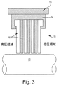
図2及び図3を参照すると、シャフトシール又はシングルシール10は、回転シャフトのようなロータ12とステータ15に取付けられたハウジング14との間における高圧領域から低圧領域への軸方向漏洩を減少させる働きをする。シャフトシール10には、その根元部において対面関係(すなわち、面対面接合)の状態でハウジング14に固定された複数の弾性プレート部材16が設けられ、次にハウジング14が、ステータ15と組立てられる。この弾性プレート部材16の構成により、ハウジング14と回転シャフト12との間にシールリングが形成される。
Referring to FIGS. 2 and 3, the shaft seal or
本明細書で説明する例示的なシングルシールは、図4に示すように、少なくとも2種類の弾性プレート部材16A、16Bを含む。弾性プレート部材16A、16Bは、交互に重ね合される。図4に示すように、弾性プレート部材16A、16Bの各々は、くしに類似しており、複数のシングル18を含む。隣接する弾性プレート部材16A、16Bは、シングル18が軸方向漏洩方向に少なくとも部分的に千鳥状配置されるように、互いに配置される。上述のように、本説明においての軸方向とは、ターボ機械の軸線を意味する。すなわち、図1に示す従来型のリーフシール構造では、リーフLは、ロータRに対して緊密に近接させてパックされており、その結果としてリーフ根元部において軸方向の漏洩を引き起こす可能性があるギャップGが生じる。本明細書で説明するシングルシール10では、隣接する弾性プレート部材16A、16Bを重ねて、その構成要素のシングル18が少なくとも部分的に千鳥状配置されて、従来型のリーフシールにおけるギャップGによる軸方向漏洩を軽減するようにする。図2には、シングル18を軸方向漏洩方向に千鳥状配置した状態で示している。また、図9〜図11を参照すると、図9は、シール根元部における蛇行漏洩流路を示している。これらの図は、2つの重ねた弾性プレート部材の組(軸方向ビューにおいて見られるように)のみを示しているが、シール外径、シール内径、リーフ長さ、リーフ剛性などのようなシール10の全体要件及び幾何学形状制約条件に応じて2つよりも多い組を同じ方式で重ねるようにすることもできる。
The exemplary single seal described herein includes at least two types of
図4に示すように、シングル18は、円周方向ビューにおいて矩形であるのが好ましい。しかしながら、本発明は、代わりに他の形状を使用することができるので、この形状に限定しようとするものではない。例えば、それに限定されないが矩形、T字形、段部状、三角形、台形、楕円形、六角形など又はその他の不規則な形状のようなあらゆる形状を特定の用途及びその要件に適するものとすることができる。図22には、別の形状の例示的な弾性プレート部材を示している。さらに、図9〜図11に見られるように、個々のシングルの断面は矩形であるが、本発明は、この断面形状に限定されるものではない。所定の用途に応じて、楕円形、六角形又はその他の断面形状も利用することができる。シングルシール組立体当りの全シングル18の数は、特定の用途での必要に応じて2つほどの少数から、例えば図3に示す7つのようなあらゆる多くの数まで変化させることができる。一般的に、シングルシールにおけるより多くのシングルの数は、そのことが漏洩流路(図9参照)における回旋数を増加させるので、シール性能を高めることができる。さらに、シングル18の幅は、図3に示すように、シングルシール組立体の範囲内で変化させることができる。
As shown in FIG. 4, the single 18 is preferably rectangular in the circumferential view. However, the present invention is not intended to be limited to this shape, as other shapes can be used instead. For example, any shape such as but not limited to rectangular, T-shaped, stepped, triangular, trapezoidal, elliptical, hexagonal, or any other irregular shape shall be suitable for a particular application and its requirements. Can do. FIG. 22 shows an exemplary elastic plate member of another shape. Furthermore, as can be seen in FIGS. 9 to 11, the cross section of each single is rectangular, but the present invention is not limited to this cross sectional shape. Depending on the predetermined application, oval, hexagonal or other cross-sectional shapes can also be utilized. The number of
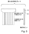
図5は、隣接する弾性プレート部材16A、16Bを示す軸方向ビューである。隣接する弾性プレート部材16A、16Bのシングル18を相対的に位置決めすることにより、シングルシール10は、隣接する弾性プレート部材16A、16Bのシングル18をそのそれぞれの先端部において挿置して、該隣接する弾性プレート部材16A、16Bのその先端部における厚さが単一の弾性プレート部材の厚さに事実上等しくなるようにすることが可能になる。従って、互いに重ね合わされた弾性プレート部材16A及び16Bにより、根元部において弾性プレート厚さの2倍でありかつ先端部において弾性プレート厚さに等しい有効厚さを有する幾何学形状が得られる。図5における軸方向ビューは、シール根元部における2つのプレート厚さがシール先端部における単一のプレート厚さに徐々に移行するのを示しているが、シングルシール10は、シール根元部における有効厚さが弾性プレート厚さの非整数倍となるように設計することができる。同様に、シングル18は、シール根元部においていかなる重なりも存在しないような図5とは異なり、根元部自体において部分的重なりを有することができる。シールにおける有効厚さの選択は一般的に、シール外径、シール内径、弾性プレート長さ、弾性プレート剛性などのようなシールの全体要件及び幾何学形状制約条件によって決められる。
FIG. 5 is an axial view showing adjacent
図1に示すような従来型のリーフシールでは、大きな漏洩通路が、真っ直ぐな遮るものがない流れライを許すリーフ根元部におけるギャップGにより生じている。本明細書で説明するシングルシール10では、根元部において千鳥状配置のシングル構成により、従来型のブラシシール(図9における漏洩流路を参照)に類似した形態で軸方向漏洩が大きく減少する。さらに、くし状の弾性プレート構造における各シングル18は、高い軸方向剛性及び低い半径方向剛性を維持し、従って従来型のリーフシールの利点を保持する。実際には、高い軸方向剛性は、シングル18が隣接するシングル18を拘束する又は隣接するシングル18に絡みつかないことを保証するのに役立つ。
In a conventional leaf seal such as that shown in FIG. 1, a large leakage path is created by a gap G in the leaf root that allows a straight flow unobstructed flow lie. In the
弾性プレート部材16、従ってシングル18は、軸方向ビューで見た時に、直線状又は均一な厚さのものにするのではなく、むしろ曲線状又はテーパ状にすることができる。図6は、湾曲を有する例示的な弾性プレート部材16を示している。さらに、同一の弾性プレート部材16内の異なるシングル18は、異なるテーパ及び/又は湾曲を有することができる。
The
弾性プレート16は、以下の目的、すなわち相対的摺動時における摩擦、磨耗及び発熱を最少にすること、製造時において拡散障壁として作用すること、高温度運転を可能にすること及びシール寿命を向上させることの1つ又はそれ以上を達成するために、特殊材料で被覆するか又は表面処理することができる。弾性プレート先端部に極めて接近しているロータの表面もまた、上記又は他の理由のために被覆することができる。共通の被覆方法には、2〜3例を挙げると、物理蒸着法、溶射法及び電着法が含まれる。被覆材料には、それに限定されないが、窒化チタン、窒化ジルコニウム、固体滑剤を伴ったニッケルクロム−炭化クロム、ニッケルなどが含まれる。
The
各弾性プレート及び/又はシングルは、それに限定されないが、位置合わせ、固定及び間隔取りのような組立て段階を可能にする、根元部における付加的機構を有することができる。一般的な実施例は、図3及び図4に示す弾性プレート根元部におけるT字形機構23である。また、図7、図8、図13、図18及び図22も参照されたい。
Each elastic plate and / or single may have additional features at the root that allow assembly steps such as, but not limited to, alignment, fixation and spacing. A typical embodiment is a T-shaped
さらに、図7及び図8における円周方向ビューに見られる、固定シェル15又はハウジング14に取付けられたリング36のような垂直機構をさらに設けることができる。リング36は、シングルの軸方向前方 (前方リング36A) に、シングルの軸方向後方 (後方リング36B) に、シングルの列間 (図8における中間リング36C) に、又はシングル内部 (図7における内部リング36D) に配置し、それによって、シングル18に対して軸方向支持を与え、さらに軸方向漏洩流を減少させ、またリフト、ブローダウン及びツイストのようなシングルの撓み動作に対する制御を行うことができる。
Further, a vertical mechanism such as a
図4を参照すると、弾性プレート部材16A、16Bは、ワイヤEDM、スタンピング、エッチングなどのようなあらゆる好適な方法を使用して個々に製作することができる。製作した後、弾性プレート部材16A、16Bは、例えばT字形セクション23のような位置合わせ機構を使用して交互に組立てられかつシール根元部において溶接などによって接合される。それに代えて、隣接する弾性プレート部材16A、16Bは、図12〜図13に示すように、単一の部品として共に製作し、次にリーフ根元部を通過する線24に沿って折り畳むことができる。T字形セクション23は、他の同様の折り畳んだシングル構造ペアとの間での位置合わせ及び組立てを可能にするように組み込むことができる。折り畳み線24は、コイニング、エッチングなどによってマーク付けすることができる。
Referring to FIG. 4, the
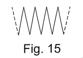
図14〜図18には、弾性プレート部材を製作するための別のやり方を示す。図14は、交互構造の弾性プレート部材16A、16Bとそれら部材間の折り畳み線24とを含む連続したストリップ材料22のロールを示している。弾性プレート部材16A及び16Bの構造は、例えばエッチング、パンチング、スタンピング、又はEDMなどのような方法によってストリップ材料22上に形成することができる。図14における陰影領域は、上記のような方法によって取り除かれる。この段階に続いて、ストリップ材料22は、図15に示すように折り畳み線24に沿って交互にアコーディオン形状に折り畳むことができる。折り畳み線24はまた、パンチング又はエッチング工程の一部として形成することもできる。折り畳まれると、アコーディオン形状は、緊密に重ね合せ、例えばワイヤEDMを使用して線(1)26に沿ってトリム加工し、溶接などを使用して線(2)28(図16)に沿って接合することができる。得られた弾性プレート部材16の組立体は次に、所望の曲率に折り畳み、シール10の他の構成部品に取付けることができる。さらに、アコーディオンは、図17に示すように製作することができ、この場合には、弾性プレート部材16は線(1)30及び線(3)32に沿って接合され、また弾性プレート部材16は線(2)34に沿って切断される。この構成により、2つのシングルシール組立体が同時に製作される。
14-18 show another way to fabricate the elastic plate member. FIG. 14 shows a roll of
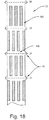
さらに、図18に示すように、ストリップ材料22には、その後の位置合わせ及び組立ての目的のために、T字形セクション23を組み込むことができる。折り畳み線24に沿って交互に折り畳んだ後に、得られたアコーディオン状スタックは、一端部で接合し、また他端部でトリム加工することができる。弾性プレートスタックの接合端部は次に、スタックのT字形セクションを収容する必要な湾曲部を備えたハウジング内に嵌挿することができる。
Further, as shown in FIG. 18, the
パンチング段階と折り畳み段階との間に、付加的なバリ取り段階を含ませることができ、この段階において、折り畳んでいない連続ストリップが紙やすり又は同様なバリ取り装置間を通過するようにすることができる。上記の製造段階の全てを一連の形態で連続して実行する単一の機械を設計又は構成することができる。 An additional deburring step can be included between the punching step and the folding step so that the unfolded continuous strip passes between a sandpaper or similar deburring device. it can. A single machine can be designed or constructed that performs all of the above manufacturing steps in succession in a series of forms.
パンチング段階の一部として、シール根元領域におけるストリップ材料上に調整深さのディンプルを形成して、部材間のあらゆる必要なスペースを形成するようにすることができる。調整厚さの被膜のような他のスペース機構もまた、組み込むことができる。 As part of the punching step, dimples of adjusted depth can be formed on the strip material in the seal root region to form any necessary space between the members. Other space features, such as a controlled thickness coating, can also be incorporated.
上記の方法は、シール根元部において整数倍の弾性プレート有効厚さを可能にする製作方法を提供する。その1つを以下に説明するが、シール根元部において分数重なり(軸方向ビューにおいて見られるような)又は非整数倍の弾性プレート有効厚さ可能にすることができる他の実施可能な製造方法を考えることができる。 The above method provides a fabrication method that allows for an integral multiple effective elastic plate thickness at the seal root. One of them is described below, but other feasible manufacturing methods that can allow fractional overlap (as seen in the axial view) or non-integer multiple elastic plate effective thickness at the seal root. Can think.
シングルシールを製作するさらに別の方法は、従来型のリーフシールを使用し、この従来型のリーフシールを、ワイヤEDMなどを使用して図19に示す切断線38に沿って様々な厚さの幾つかの平行なセグメントに垂直に切断することができる。これにより、図20に示すスペーサシム40を使用して軸方向に間隔を置いて配置された複数のシールセグメントが得られる。その後、このセグメントは、図21に示すように、シール軸線の周りで互いに交互に回転させて、シングル間に必要な千鳥状配置を形成する。このことが達成されると、セグメントは再接合される。
Yet another method of making a single seal is to use a conventional leaf seal, which can be of varying thickness along the cutting
本明細書で説明したシングルシールは、幾何学形状的にも機能的にも従来型のリーフシールと従来型のブラシシールとの間の合成物である。上記のシングルシールの幾何学構成は、該幾何学構成がシングルの千鳥状配置によるブラシシールの低い漏洩特質と共にプレート状シングルによるリーフシールの高い圧力差性能とを保持するようになる。 The single seal described herein is a composite between a conventional leaf seal and a conventional brush seal, both geometrically and functionally. The single seal geometry described above maintains the high pressure differential performance of the leaf seal with a plate-like single as well as the low leakage characteristics of the brush seal with a single staggered arrangement.
現在最も実用的かつ好ましい実施形態であると考えられるものに関して本発明を説明してきたが、本発明は、開示した実施形態に限定されるものではなく、逆に特許請求の範囲の技術思想及び技術的範囲内に含まれる様々な変更及び均等な構成を保護しようとするものであることを理解されたい。 Although the present invention has been described with respect to what is presently considered to be the most practical and preferred embodiments, the invention is not limited to the disclosed embodiments, but conversely, the technical ideas and techniques of the claims It should be understood that various changes and equivalent arrangements included within the scope are intended to be protected.
10 シングルシール
12 ロータ
14 ハウジング
15 ステータ
16 弾性プレート部材
16A、16B 弾性プレート部材
18 シングル
23 T字形機構
36 リング
36A 前方リング
36B 後方リング
36C 中間リング
36D 内部リング
24 折り畳み線
22 ストリップ材料
26 線(1)
28 線(2)
30 線(1)
32 線(3)
34 線(2)
38 切断線
40 スペーサシム
DESCRIPTION OF
28 lines (2)
30 lines (1)
32 lines (3)
34 lines (2)
38
Claims (11)
対面関係の状態で前記ステータに取付けられかつ周方向を向いた対面する面が周方向に重ね合わされて該ステータと前記回転シャフトとの間にシールリングを形成した複数の弾性プレート部材(16)を含み、
前記弾性プレート部材の各々が、複数のシングル(18)を含み、
隣接する弾性プレート部材が、前記シングルが連結せずに軸方向漏洩方向に少なくとも部分的に千鳥状配置されるように、互いに配置され、
前記ステータが、固定シェル(15)に取付け可能なハウジング(14)であり、
前記ハウジングが、対応する前記複数のシングル(18)のうちの少なくとも1つの内部に配置され、半径方向に延びる円周方向リング(36)を含む、
シャフトシール。 A shaft seal for reducing leakage between the rotating shaft (12) and the stator (14, 15),
A plurality of elastic plate members (16) that are attached to the stator in a face-to-face relationship and that face in the circumferential direction are overlapped in the circumferential direction to form a seal ring between the stator and the rotating shaft. Including
Each of the elastic plate members comprises a plurality of singles (18);
Adjacent elastic plate members are arranged together so that the singles are not connected and are at least partially staggered in the axial leakage direction,
The stator is a housing (14) attachable to a fixed shell (15);
The housing includes a circumferential ring (36) disposed within at least one of the corresponding singles (18) and extending radially.
Shaft seal.
前記隣接する弾性プレート部材のシングル(18)が、そのそれぞれの先端部において挿置されて、該隣接する弾性プレート部材のその先端部における厚さが単一の弾性プレート部材の厚さにほぼ等しくなるようになる、
請求項1に記載のシャフトシール。 The elastic plate member (16) is attached to the stator (14, 15) at its root and forms the seal ring at its tip;
The single (18) of the adjacent elastic plate members are inserted at their respective leading ends, and the thickness of the adjacent elastic plate member at the leading end is substantially equal to the thickness of the single elastic plate member. Become
The shaft seal according to claim 1.
前記隣接する弾性プレート部材のシングル(18)が、そのそれぞれの先端部において挿置されて、前記隣接する弾性プレート部材のその先端部における有効厚さが、単一の弾性プレート部材の厚さと2つの側対側接合弾性プレート部材の厚さとの間の範囲にあるようになる、
請求項1に記載のシャフトシール。 The elastic plate member (16) is attached to the stator (14, 15) at its root portion;
The single (18) of the adjacent elastic plate members is inserted at the respective front end portions thereof, and the effective thickness at the front end portion of the adjacent elastic plate members is equal to the thickness of the single elastic plate member. Will be in the range between the thickness of the two side-to-side bonded elastic plate members,
The shaft seal according to claim 1.
11. A shaft seal according to claim 10, wherein two of the adjacent elastic plate members (16) are formed from a single sheet and folded at the root end.
Applications Claiming Priority (2)
| Application Number | Priority Date | Filing Date | Title |
|---|---|---|---|
| US11/519,044 US7703774B2 (en) | 2006-09-12 | 2006-09-12 | Shaft seal using shingle members |
| US11/519,044 | 2006-09-12 |
Publications (2)
| Publication Number | Publication Date |
|---|---|
| JP2008069968A JP2008069968A (en) | 2008-03-27 |
| JP5178102B2 true JP5178102B2 (en) | 2013-04-10 |
Family
ID=38688926
Family Applications (1)
| Application Number | Title | Priority Date | Filing Date |
|---|---|---|---|
| JP2007233570A Expired - Fee Related JP5178102B2 (en) | 2006-09-12 | 2007-09-10 | Shaft seal using a single elastic plate member |
Country Status (6)
| Country | Link |
|---|---|
| US (1) | US7703774B2 (en) |
| EP (1) | EP1900983B1 (en) |
| JP (1) | JP5178102B2 (en) |
| CN (1) | CN101144542B (en) |
| AT (1) | ATE472069T1 (en) |
| DE (1) | DE602007007265D1 (en) |
Cited By (1)
| Publication number | Priority date | Publication date | Assignee | Title |
|---|---|---|---|---|
| KR101475272B1 (en) * | 2013-06-07 | 2014-12-29 | 삼성중공업 주식회사 | Sealing apparatus for wind turbine |
Families Citing this family (32)
| Publication number | Priority date | Publication date | Assignee | Title |
|---|---|---|---|---|
| US7703774B2 (en) * | 2006-09-12 | 2010-04-27 | General Electric Company | Shaft seal using shingle members |
| US7909335B2 (en) * | 2008-02-04 | 2011-03-22 | General Electric Company | Retractable compliant plate seals |
| US20100143102A1 (en) * | 2008-02-18 | 2010-06-10 | General Electric Company | Compliant plate seal with self-correcting behavior |
| US20090304493A1 (en) * | 2008-06-09 | 2009-12-10 | General Electric Company | Axially oriented shingle face seal for turbine rotor and related method |
| GB0822144D0 (en) * | 2008-12-04 | 2009-01-14 | Petrowell Ltd | Flow control device |
| US8794631B2 (en) | 2009-01-12 | 2014-08-05 | General Electric Company | Method of manufacturing of a compliant plate seal assembly |
| US8250756B2 (en) | 2009-02-20 | 2012-08-28 | General Electric Company | Method of manufacture of compliant plate seals |
| DE102009015122A1 (en) * | 2009-03-31 | 2010-10-14 | Alstom Technology Ltd. | Lamella seal for a turbomachine |
| US8272644B1 (en) | 2009-07-14 | 2012-09-25 | Florida Turbine Technologies, Inc. | Floating card seal |
| US8393859B1 (en) * | 2009-09-18 | 2013-03-12 | Florida Turbine Technologies, Inc. | Card seal for a turbine |
| GB201001072D0 (en) * | 2010-01-25 | 2010-03-10 | Rolls Royce Plc | Sealing arrangemant foa a gas turbine engine |
| US8490981B2 (en) * | 2010-02-23 | 2013-07-23 | General Electric Company | Brush seal |
| US8474827B2 (en) | 2010-06-11 | 2013-07-02 | Cmg Tech, Llc | Film riding pressure actuated leaf seal assembly |
| US9206904B2 (en) | 2010-07-08 | 2015-12-08 | Siemens Energy, Inc. | Seal including flexible seal strips |
| US8690158B2 (en) * | 2010-07-08 | 2014-04-08 | Siemens Energy, Inc. | Axially angled annular seals |
| US20130022459A1 (en) * | 2011-07-18 | 2013-01-24 | General Electric Company | Seals for reducing leakage in rotary machines |
| US20130106061A1 (en) * | 2011-10-28 | 2013-05-02 | General Electric Company | High temperature seal system |
| GB201119528D0 (en) * | 2011-11-14 | 2011-12-21 | Rolls Royce Plc | Leaf seal |
| GB201119526D0 (en) * | 2011-11-14 | 2011-12-21 | Rolls Royce Plc | Leaf seal |
| US9103224B2 (en) | 2011-12-29 | 2015-08-11 | General Electric Company | Compliant plate seal for use with rotating machines and methods of assembling a rotating machine |
| US20130341426A1 (en) * | 2012-02-10 | 2013-12-26 | United Technologies Corporation | Flexible leaf spring seal for sealing an air gap between moving plates |
| US9267602B2 (en) | 2012-11-19 | 2016-02-23 | General Electric Company | Seal assembly including partially filled gaps |
| JP5877185B2 (en) * | 2013-10-28 | 2016-03-02 | 本田技研工業株式会社 | Cold air shielding structure for vehicles |
| EP2908002B1 (en) * | 2014-02-14 | 2018-10-24 | LM Wind Power International Technology II ApS | A bulkhead assembly for a wind turbine blade |
| JPWO2016006535A1 (en) * | 2014-07-11 | 2017-06-01 | イーグル工業株式会社 | mechanical seal |
| CN104121418B (en) * | 2014-07-14 | 2017-01-11 | 宁波浙成科技咨询有限公司 | Improved sealing piece |
| US9963991B2 (en) * | 2014-10-01 | 2018-05-08 | United Technologies Corporation | Brush seal plate |
| US10954806B2 (en) * | 2014-10-10 | 2021-03-23 | Nuovo Pignone Srl | Seal for a gap between an outer and an inner cylindrical surface |
| DE102015003048B4 (en) | 2015-01-26 | 2021-10-28 | Sew-Eurodrive Gmbh & Co Kg | Sealing arrangement for gears and gears with such a sealing arrangement |
| US20170051983A1 (en) * | 2015-08-18 | 2017-02-23 | Arvos Inc. | Flexible seal for a rotary regenerative preheater |
| US10352183B2 (en) * | 2016-04-25 | 2019-07-16 | United Technologies Corporation | High temperature seal and method |
| CN108005793B (en) * | 2017-12-27 | 2019-10-18 | 中国航发四川燃气涡轮研究院 | A kind of tile sealing structure |
Family Cites Families (65)
| Publication number | Priority date | Publication date | Assignee | Title |
|---|---|---|---|---|
| US4526509A (en) * | 1983-08-26 | 1985-07-02 | General Electric Company | Rub tolerant shroud |
| US4811961A (en) * | 1988-04-08 | 1989-03-14 | Boliden Allis, Inc. | Seal for rotating cylinders such as kilns and the like |
| GB8907695D0 (en) * | 1989-04-05 | 1989-05-17 | Cross Mfg Co | Seals |
| US5031922A (en) * | 1989-12-21 | 1991-07-16 | Allied-Signal Inc. | Bidirectional finger seal |
| US6131910A (en) * | 1992-11-19 | 2000-10-17 | General Electric Co. | Brush seals and combined labyrinth and brush seals for rotary machines |
| US6131911A (en) * | 1992-11-19 | 2000-10-17 | General Electric Co. | Brush seals and combined labyrinth and brush seals for rotary machines |
| US5749584A (en) * | 1992-11-19 | 1998-05-12 | General Electric Company | Combined brush seal and labyrinth seal segment for rotary machines |
| US5755445A (en) * | 1996-08-23 | 1998-05-26 | Alliedsignal Inc. | Noncontacting finger seal with hydrodynamic foot portion |
| US5961280A (en) * | 1997-09-12 | 1999-10-05 | General Elecgtric Company | Anti-hysteresis brush seal |
| US5961125A (en) * | 1997-10-02 | 1999-10-05 | General Electric Company | Brush seal for use on rough rotating surfaces |
| US5941685A (en) * | 1997-10-14 | 1999-08-24 | General Electric Company | Brush seal for use on bumpy rotating surfaces |
| US6027121A (en) * | 1997-10-23 | 2000-02-22 | General Electric Co. | Combined brush/labyrinth seal for rotary machines |
| US6079945A (en) * | 1997-11-10 | 2000-06-27 | Geneal Electric Company | Brush seal for high-pressure rotor applications |
| GB9801864D0 (en) | 1998-01-30 | 1998-03-25 | Rolls Royce Plc | A seal arrangement |
| US6045134A (en) * | 1998-02-04 | 2000-04-04 | General Electric Co. | Combined labyrinth and brush seals for rotary machines |
| US6139018A (en) * | 1998-03-25 | 2000-10-31 | General Electric Co. | Positive pressure-actuated brush seal |
| GB2336408B (en) * | 1998-04-17 | 2002-07-24 | Rolls Royce Plc | A seal arrangement |
| CA2303151C (en) * | 1998-07-13 | 2004-08-31 | Mitsubishi Heavy Industries, Ltd. | Shaft seal and turbine using the shaft seal |
| US6053699A (en) * | 1998-07-27 | 2000-04-25 | General Electric Company | Steam turbine having a brush seal assembly |
| US6168162B1 (en) * | 1998-08-05 | 2001-01-02 | General Electric Co. | Self-centering brush seal |
| US5971400A (en) * | 1998-08-10 | 1999-10-26 | General Electric Company | Seal assembly and rotary machine containing such seal assembly |
| US6105966A (en) * | 1998-08-10 | 2000-08-22 | General Electric Company | Brush seal segment |
| US6250640B1 (en) * | 1998-08-17 | 2001-06-26 | General Electric Co. | Brush seals for steam turbine applications |
| US6030175A (en) * | 1998-09-23 | 2000-02-29 | General Electric Company | Hybrid seal and rotary machine containing such hybrid seal |
| US6250641B1 (en) * | 1998-11-25 | 2001-06-26 | General Electric Co. | Positive biased packing ring brush seal combination |
| US6196550B1 (en) * | 1999-02-11 | 2001-03-06 | Alliedsignal Inc. | Pressure balanced finger seal |
| US6364316B1 (en) * | 1999-02-11 | 2002-04-02 | Honeywell International Inc. | Dual pressure balanced noncontacting finger seal |
| US6286211B1 (en) * | 1999-03-24 | 2001-09-11 | General Electric Company | Method for making a brush-tooth seal |
| US6139019A (en) * | 1999-03-24 | 2000-10-31 | General Electric Company | Seal assembly and rotary machine containing such seal |
| US6261057B1 (en) * | 1999-10-04 | 2001-07-17 | General Electric Company | Arrangement and method for accurately radially locating a turbine brush seal |
| US6308958B1 (en) * | 1999-10-12 | 2001-10-30 | General Electric Company | Arrangement and method for radially positioning a turbine brush seal |
| US6367806B1 (en) * | 1999-12-27 | 2002-04-09 | General Electric Company | Seal arrangement for a rotary machine such as a turbine |
| US6331006B1 (en) * | 2000-01-25 | 2001-12-18 | General Electric Company | Brush seal mounting in supporting groove using flat spring with bifurcated end |
| DE10006298A1 (en) * | 2000-02-12 | 2001-08-16 | Abb Patent Gmbh | Seal for rotating parts |
| US6428009B2 (en) * | 2000-04-03 | 2002-08-06 | John F. Justak | Robust hydrodynamic brush seal |
| DE10017643B4 (en) * | 2000-04-08 | 2005-10-20 | Mtu Aero Engines Gmbh | Seal in non-hermetic design |
| CN1149343C (en) * | 2000-06-27 | 2004-05-12 | 山东电力研究院 | Contact-type mechanical seal for axle |
| GB2365082B (en) * | 2000-07-18 | 2003-10-08 | Rolls Royce Plc | A method of manufacturing seals |
| US6460857B1 (en) * | 2000-09-11 | 2002-10-08 | General Electric Company | Brush seal segment end bristle protection and flexibility maintenance device and methods of forming the segment |
| US6439844B1 (en) * | 2000-12-11 | 2002-08-27 | General Electric Company | Turbine bucket cover and brush seal |
| US6431827B1 (en) * | 2000-12-21 | 2002-08-13 | General Electric Company | Bucket tip brush seals in steam turbines and methods of installation |
| CA2359933C (en) * | 2001-02-08 | 2006-03-14 | Mitsubishi Heavy Industries, Ltd. | Shaft seal and gas turbine |
| US7578509B2 (en) * | 2001-02-23 | 2009-08-25 | Cmg Tech, Llc | Seal assembly and rotary machine containing such seal |
| US6644667B2 (en) * | 2001-02-23 | 2003-11-11 | Cmg Tech, Llc | Seal assembly and rotary machine containing such seal |
| JP4824225B2 (en) * | 2001-08-29 | 2011-11-30 | イーグル工業株式会社 | Plate brush seal device |
| JP4675530B2 (en) * | 2001-09-28 | 2011-04-27 | イーグル工業株式会社 | Plate brush seal |
| JP3702212B2 (en) * | 2001-09-28 | 2005-10-05 | 三菱重工業株式会社 | Shaft seal mechanism and turbine |
| JP4751552B2 (en) * | 2001-09-28 | 2011-08-17 | イーグル工業株式会社 | Plate brush seal and plate brush seal device |
| JP3593082B2 (en) | 2001-10-09 | 2004-11-24 | 三菱重工業株式会社 | Shaft seal mechanism and turbine |
| US6786487B2 (en) * | 2001-12-05 | 2004-09-07 | General Electric Company | Actuated brush seal |
| JP4054607B2 (en) * | 2002-05-23 | 2008-02-27 | イーグル工業株式会社 | Plate brush seal |
| US6786488B2 (en) * | 2002-07-18 | 2004-09-07 | Mitsubishi Heavy Industries, Ltd. | Seal structure, turbine having the same, and leak-preventing seal system for rotating shaft |
| US6685427B1 (en) * | 2002-07-23 | 2004-02-03 | General Electric Company | Brush seal for a rotary machine and method of retrofitting |
| US6854735B2 (en) * | 2002-08-26 | 2005-02-15 | General Electric Company | In situ load sharing brush seals |
| US6790001B2 (en) * | 2002-11-22 | 2004-09-14 | General Electric Company | Brush seal arrangement for high pressure applications |
| GB0307291D0 (en) * | 2003-03-29 | 2003-05-07 | Rolls Royce Plc | A seal arrangement |
| JP4009555B2 (en) * | 2003-05-20 | 2007-11-14 | イーグル・エンジニアリング・エアロスペース株式会社 | Plate brush seal device |
| CN1324221C (en) | 2003-05-21 | 2007-07-04 | 三菱重工业株式会社 | Shaft seal mechanism |
| JP4081719B2 (en) * | 2003-05-30 | 2008-04-30 | イーグル・エンジニアリング・エアロスペース株式会社 | Plate brush seal device |
| GB2411931A (en) * | 2004-03-08 | 2005-09-14 | Alstom Technology Ltd | A leaf seal arrangement |
| JP3917993B2 (en) * | 2004-08-10 | 2007-05-23 | 三菱重工業株式会社 | A shaft seal mechanism, a structure for attaching the shaft seal mechanism to a stator, and a turbine including these. |
| US7413194B2 (en) * | 2004-10-28 | 2008-08-19 | Rolls-Royce Plc | Pressure balanced annular seal |
| GB0423923D0 (en) * | 2004-10-28 | 2004-12-01 | Rolls Royce Plc | Segmented annular seal for a gas turbine engine |
| US7419164B2 (en) * | 2006-08-15 | 2008-09-02 | General Electric Company | Compliant plate seals for turbomachinery |
| US7703774B2 (en) * | 2006-09-12 | 2010-04-27 | General Electric Company | Shaft seal using shingle members |
-
2006
- 2006-09-12 US US11/519,044 patent/US7703774B2/en not_active Expired - Fee Related
-
2007
- 2007-09-04 DE DE602007007265T patent/DE602007007265D1/en active Active
- 2007-09-04 EP EP07115632A patent/EP1900983B1/en not_active Not-in-force
- 2007-09-04 AT AT07115632T patent/ATE472069T1/en not_active IP Right Cessation
- 2007-09-10 JP JP2007233570A patent/JP5178102B2/en not_active Expired - Fee Related
- 2007-09-12 CN CN200710148959.XA patent/CN101144542B/en not_active Expired - Fee Related
Cited By (1)
| Publication number | Priority date | Publication date | Assignee | Title |
|---|---|---|---|---|
| KR101475272B1 (en) * | 2013-06-07 | 2014-12-29 | 삼성중공업 주식회사 | Sealing apparatus for wind turbine |
Also Published As
| Publication number | Publication date |
|---|---|
| CN101144542A (en) | 2008-03-19 |
| ATE472069T1 (en) | 2010-07-15 |
| DE602007007265D1 (en) | 2010-08-05 |
| CN101144542B (en) | 2013-05-22 |
| US7703774B2 (en) | 2010-04-27 |
| EP1900983B1 (en) | 2010-06-23 |
| US20080061513A1 (en) | 2008-03-13 |
| JP2008069968A (en) | 2008-03-27 |
| EP1900983A1 (en) | 2008-03-19 |
Similar Documents
| Publication | Publication Date | Title |
|---|---|---|
| JP5178102B2 (en) | Shaft seal using a single elastic plate member | |
| JP5038789B2 (en) | Seal assembly and rotary machine with "L" shaped butt gap seal between segments | |
| US7604241B2 (en) | Seals for turbines and turbo machinery | |
| JP5059513B2 (en) | Compliant plate seal for turbomachinery | |
| US7255352B2 (en) | Pressure balanced brush seal | |
| US8100404B2 (en) | Leaf seal arrangement | |
| JP4689882B2 (en) | Plate brush seal device | |
| US4971336A (en) | Enhanced performance brush seals | |
| US7828297B2 (en) | Leaf seal, in particular for a gas turbine | |
| US6550777B2 (en) | Split packing ring segment for a brush seal insert in a rotary machine | |
| US20020117806A1 (en) | Seal assembly and rotary machine containing such seal | |
| JP5546420B2 (en) | Turbine | |
| JP5864836B2 (en) | Seal member, assembly and method | |
| JP5398651B2 (en) | Shaft sealing mechanism and rotating machine equipped with the same | |
| GB2404702A (en) | A leaf seal assembly and rotary machine containing such a seal assembly | |
| EP2540985B1 (en) | Repairable double sided brush seal | |
| JP2001355743A (en) | Non-enclosed sealing structure | |
| JPH08246806A (en) | Stator for turbomachinery | |
| KR100692229B1 (en) | Turbomachinery and method of operating turbomachinery | |
| JP2007138948A (en) | Seal member, assembly and its method | |
| EP1186812B1 (en) | Brush seal segment end bristle protection and flexibility maintenance device and methods of forming the segment | |
| EP3059397B1 (en) | Shaft seal device, rotary machine, and method for manufacturing shaft seal device | |
| JP5116833B2 (en) | Plate brush seal device |
Legal Events
| Date | Code | Title | Description |
|---|---|---|---|
| A621 | Written request for application examination |
Free format text: JAPANESE INTERMEDIATE CODE: A621 Effective date: 20100831 |
|
| RD04 | Notification of resignation of power of attorney |
Free format text: JAPANESE INTERMEDIATE CODE: A7424 Effective date: 20100831 |
|
| A521 | Request for written amendment filed |
Free format text: JAPANESE INTERMEDIATE CODE: A523 Effective date: 20110823 |
|
| A977 | Report on retrieval |
Free format text: JAPANESE INTERMEDIATE CODE: A971007 Effective date: 20120606 |
|
| A131 | Notification of reasons for refusal |
Free format text: JAPANESE INTERMEDIATE CODE: A131 Effective date: 20120612 |
|
| A521 | Request for written amendment filed |
Free format text: JAPANESE INTERMEDIATE CODE: A523 Effective date: 20120905 |
|
| A01 | Written decision to grant a patent or to grant a registration (utility model) |
Free format text: JAPANESE INTERMEDIATE CODE: A01 Effective date: 20121211 |
|
| A61 | First payment of annual fees (during grant procedure) |
Free format text: JAPANESE INTERMEDIATE CODE: A61 Effective date: 20130108 |
|
| R250 | Receipt of annual fees |
Free format text: JAPANESE INTERMEDIATE CODE: R250 |
|
| R250 | Receipt of annual fees |
Free format text: JAPANESE INTERMEDIATE CODE: R250 |
|
| LAPS | Cancellation because of no payment of annual fees |